Extending the performance, fuel efficiency and stability of stoichiometric spark ignition natural gas engines - Gas engine research at KCFP 2007-2012
←
→
Page content transcription
If your browser does not render page correctly, please read the page content below
SGC Rapport 2013:286

Extending the performance, fuel efficiency and
stability of stoichiometric spark ignition natural gas
engines – Gas engine research at KCFP 2007–2012
(Utökad prestanda, bränsleeffektivitet och stabilitet för stökiometriska naturgasdrivna
tändstiftsmotorer – Gasmotorforskning på KCFP 2007–2012)
Mehrzad Kaiadi, Per Tunestål, Ashish Shah

                            ”Catalyzing energygas development
                                 for sustainable solutions”
Extending the performance, fuel efficiency and stability of stoichiometric
spark ignition natural gas engines – Gas engine research at KCFP 2007-2012
(Utökad prestanda, bränsleeffektivitet och stabilitet för stökiometriska
naturgasdrivna tändstiftsmotorer – Gasmotorforskning på KCFP 2007-2012)

Mehrzad Kaiadi, Per Tunestål, Ashish Shah

Denna studie har finansierats av:
Energimyndigheten
E.ON Gas Sverige AB
Göteborgs Energi AB
Lunds Energikoncernen (publ) AB
Öresundskraft AB
Scania CV AB
Saab Automobile Powertrain
Volvo Car Corporation AB
Volvo Powertrain AB
AB Volvo Penta
Cargine Engineering AB
Caterpillar Inc.
Chevron Energy Technology Company, a division of Chevron U.S.A. Inc.
Finnveden Powertrain AB
Hoerbiger Control Systems AB
National Instruments Sverige AB
Toyota Motor Corporation
Wärtsilä Finland Oy

© Svenskt Gastekniskt Center AB

Postadress och Besöksadress   Telefonväxel          E-post
Scheelegatan 3                040-680 07 60         info@sgc.se
212 28 MALMÖ
                              Telefax               Hemsida
                              0735-279104           www.sgc.se
SGC Rapport 2013:286

2              Svenskt Gastekniskt Center AB, Malmö – www.sgc.se
SGC Rapport 2013:286

Svenskt Gastekniskt Center AB, SGC
SGC är ett spjutspetsföretag inom hållbar utveckling med ett nationellt uppdrag. Vi arbetar
under devisen ”Catalyzing energygas development for sustainable solutions”. Vi
samordnar branschgemensam utveckling kring framställning, distribution och användning
av energigaser och sprider kunskap om energigaser. Fokus ligger på förnybara gaser från
rötning och förgasning. Tillsammans med företag och med Energimyndigheten och dess
Samverkansprogram Energiteknik utvecklar vi nya möjligheter för energigaserna att bidra
till ett hållbart samhälle. Tillsammans med våra fokusgrupper inom Rötning, Förgasning
och bränslesyntes, Lagring och transport, Industri och hushåll och Gasformiga drivmedel
identifierar vi frågeställningar av branschgemensamt intresse att genomföra forsknings-,
utvecklings och/eller demonstrationsprojekt kring. Som medlem i den europeiska
gasforskningsorganisationen GERG fångar SGC också upp internationella perspektiv på
utvecklingen inom energigasområdet.

Resultaten från projekt drivna av SGC publiceras i en särskild rapportserie – SGC
Rapport. Rapporterna kan laddas ned från hemsidan – www.sgc.se. Det är också möjligt
att prenumerera på de tryckta rapporterna. SGC svarar för utgivningen av rapporterna
medan rapportförfattarna svarar för rapporternas innehåll.

SGC ger också ut faktabroschyrer kring olika aspekter av energigasers framställning,
distribution och användning. Broschyrer kan köpas via SGC:s kansli.

SGC har sedan starten 1990 sitt säte i Malmö. Vi ägs av E.ON Gas Sverige AB,
Energigas Sverige, Swedegas AB, Göteborg Energi AB, Lunds Energikoncernen AB
(publ) och Öresundskraft AB.

Malmö 2013

Martin Ragnar
Verkställande direktör

Svenskt Gastekniskt Center AB, Malmö – www.sgc.se                                             3
SGC Rapport 2013:286

Swedish Gas Technology Centre, SGC
SGC is a leading-edge company within the field of sustainable development having a
national Swedish assignment. We work under the vision of “Catalyzing energygas
development for sustainable solutions”. We co-ordinate industry-wide technical
development on the production, distribution and utilization of energygases and
disseminate knowledge on energygases. Focus is on renewable gases from anaerobic
digestion and gasification. Together with private companies and with the Swedish Energy
Agency and its frame program Co-operational program in Energygas technology we
develop new solutions where energygases could provide benefits for a sustainable
society. Together with our focus groups on Anaerobic digestion, Gasification and fuel
synthesis, Storage and transportation, Industry and household and Gaseous fuels we
identify issues of common interest in the industry to conduct joint research, development
and/or demonstrations projects on. As a member of the European gas research
organization GERG, SGC provides an international perspective to the development within
the Swedish energygas sector.

Results from the SGC projects are published in a report series – SGC Rapport. The
reports can be downloaded free of charge from our website – www.sgc.se. It is also
possible to subscribe to the printed reports. SGC is responsible for the publishing of the
reports, whereas the authors of the report are responsible for the content of the reports.

SGC also publishes fact brochures and the results from our research projects in the report
series SGC Rapport. Brochures can be purchased via the website.

SGC is since the start in 1990 located in Malmö. We are owned by E.ON Gas Sverige AB,
Energigas Sverige, Swedegas AB, Göteborg Energi AB, Lunds Energikoncernen AB
(publ) and Öresundskraft AB.

Malmö, Sweden 2013

Martin Ragnar
Chief Executive Officer

4                                               Svenskt Gastekniskt Center AB, Malmö – www.sgc.se
SGC Rapport 2013:286

Authors’ foreword
The gas engine project at Lund University has previously explored extending the
performance, fuel efficiency and stability of SI natural gas engines. The first NG
engine activities started in the beginning of the 1990s. In the first and second
phase of the natural gas engine project a lot of time was spent to measure
turbulence and to investigate how the combustion chamber design influenced
combustion parameters and emissions. Those experiments were applied on a
single-cylinder Volvo engine TD102.
  The third phase of the natural gas engine activities started from 2000 and ended
in 2003. A 6-cylinder turbocharged Volvo engine (i.e. TG103) was used in this
phase. Different experiments were performed including investigating different
locations for fuel injection, investigation of cylinder-to-cylinder and cycle-to-cycle
variations in a Lean Burn natural gas engine and a study to compare Lean Burn
natural gas engine versus stoichiometric operation with EGR. The results from this
phase showed that the stoichiometric operation is a better choice than lean
operation since by using a three-way catalyst the emissions level can be kept at
very low levels and differences in efficiency are not significant.
  The fourth phase of the project started in the beginning of 2007. Based on the
results from phase three, the engine operating concept was decided to be
stoichiometric and the research activities focused mostly on the problems
associated with this type of operation. Extending the dilution limit of the engine and
developing closed-loop control to operate the engine at its dilution limit has been
the main method to improve throttle losses. A new method for calculating cyclic
variation was developed that significantly improved the transient capability of the
engine control system. The method consequently applied on a closed-loop dilution
limit control which resulted in improvement in specific fuel consumption with
acceptable transient capability. Ion current signals were studied at different
operation condition. Cyclic variation of ion current integral was found to be a
robust combustion stability parameter which can be used as more economical
alternative to cyclic variation derived from pressure sensors. Moreover, the key
features to improve the engine performance are identified as, right amount of EGR
at different operating regions, right compression ratio, Variable Geometry
Turbocharger (VGT), high turbulent pistons, long route EGR system and model-
based control. The started research activities from phase four prolonged and a
part of that performed in phase five.
  The existing phase started in the beginning of 2010 and it is expected to end in
2012. Since the beginning of 2011 the project mainly focuses on exploring
alternative ignition techniques as after completion of all previous phases it was
observed that the capability of conventional spark plug ignition system was the
factor limiting the extent of dilution and hence emission reduction and efficiency
improvement. Two most feasible alternative ignition systems were identified,
namely diesel pilot injection and pre-chamber type ignition system but it was soon
realized that the former has already received considerable attention as there are
products in the market under different names like The Hardstaff OIGI® (Oil Ignition
Gas Injection), Westport’s High-Pressure Direct Injection (HPDI) applicable to a
wide range of engines. Comparatively, however, the concept of pre-chamber
ignition has received limited attention and is mainly applied to stationary or large

Svenskt Gastekniskt Center AB, Malmö – www.sgc.se                                        5
SGC Rapport 2013:286

bore marine engine which do not face as severe speed and load transients as
experienced by a heavy duty engine for mobile application. Reasons behind this
are believed to be limited knowledge about the mechanism of ignition resulting
from a pre-chamber type ignition device and hence gaining deeper insight into this
mechanism is currently the objective of the gas engine project.
  This report gives a summary of the results from the first three phases of the gas
engine activities at Lund University but the main focus of the report is on phase
four and five.
  To the project a reference group has been linked consisting of the following
persons;
Mattias Svensson and Corfitz Nelsson, Swedish Gas Technology Centre
Ingemar Magnusson, Volvo Global Trucks Technology
Folke Fritzson, Scania
Kenth Svensson, Caterpillar
Jari Hyvönen, Wärtsilä

6                                          Svenskt Gastekniskt Center AB, Malmö – www.sgc.se
SGC Rapport 2013:286

Summary
Most heavy-duty engines are diesel operated. Severe emission regulations, high
fuel prices, high technology costs (e.g. catalysts, fuel injection systems) and un-
sustainable fuel supplies are enough reasons to convince engine developers to
explore alternative technologies or fuels. Using natural gas/biogas can be a very
good alternative due to the attractive fuel properties regarding emission reduction
and engine operation. Heavy-duty diesel engines can be easily converted for natu-
ral gas operation which is a very cost effective process for producing gas engines.
However, due to the high throttle losses and low expansion ratio the overall engine
efficiency is lower than the corresponding diesel engines. Moreover the lower den-
sity of natural gas results in lower maximum power level.
   In this project (phase 4) key features and strategies which result in improved
efficiency, increased maximum power and improved transient capability of heavy-
duty natural gas engines have been identified, validated and suggested. High EGR
rates combined with turbocharging has been identified as a promising way to in-
crease the maximum load and efficiency of heavy-duty gas engines. With stoichi-
ometric conditions a three way catalyst can be used and thus regulated emissions
can be kept at very low levels. Obtaining reliable spark ignition is difficult however
with high dilution and there will be a limit to the amount of EGR that can be toler-
ated for each operating point. Extending the dilution limit of the engine and devel-
oping closed-loop control to operate the engine at its dilution limit has been the
main method to reduce throttle losses.
   Information about the combustion stability can be derived either from pressure or
ion-current data measured inside the cylinder. The reliability and robustness of the
combustion stability parameters derived from pressure and ion-current data were
validated in separate studies. A new method for calculating cyclic variation was
developed that significantly improved the transient capability of the engine control
system. The method consequently applied on a closed-loop dilution limit control.
Only applying closed-loop control to operate the engine at its dilution limit resulted
in 4.5% to 8% improvement in specific fuel consumption at 1200 RPM.
   The dilution limit can also be extended by replacing the combustion chambers
with high turbulence pistons which enhances the combustion. New pistons were
designed to increase the turbulence level to shorten the combustion duration.
   The new piston modification resulted in changes in the exhaust gas characteris-
tics. These changes, together with the fact that Variable Geometry Turbocharger
(VGT) has big potentials to reduce further the throttle losses were the motivation to
replace the turbocharger with a well-matched VGT. It was demonstrated that VGT
can be used instead of throttle in more than 60% of the whole operating range of
the engine meaning no throttle losses in this area.
   Since reliable spark ignition is challenging at high boost and dilution levels pre-
chambers have been considered as a solution in phase 5 of the project. Unfueled
pre-chamber spark plugs have been evaluated and found to provide marginal im-
provement of the dilution limit. Problems with pre-ignition limit their usefulness at
high load however. Ongoing work with fueled pre-chambers should provide better
opportunities.
   In summary the key features to improve the performance of a stoichiometrically
operated natural gas engine are identified as: right amount of EGR at different op-

Svenskt Gastekniskt Center AB, Malmö – www.sgc.se                                        7
SGC Rapport 2013:286

erating regions, right compression ratio, VGT, high turbulence pistons, powerful
ignition, long route EGR system and model-based control. Applying the combina-
tion of these strategies resulted in up to 10% improvement in specific fuel con-
sumption while preserving combustion stability.

8                                         Svenskt Gastekniskt Center AB, Malmö – www.sgc.se
SGC Rapport 2013:286

Sammanfattning på svenska
Majoriteten av tunga motorer är idag dieselmotorer. Strikta emissionskrav, höga
tillverkningskostnader (t.ex. katalysatorer, bränsleinsprutningssystem) och icke
hållbar bränsleförsörjning är tillräckliga orsaker för att övertyga motorutvecklare att
undersöka alternativa teknologier och bränslen. Naturgas/biogas kan utgöra ett
mycket konkurrenskraftigt alternativ pga. gynnsamma bränsleegenskaper för mo-
tordrift och minskade emissioner. Det är relativt okomplicerat att konvertera tunga
dieselmotorer till ottomotorer med naturgasdrift och därigenom är detta ett kost-
nadseffektivt sätt att producera gasmotorer. Pga. höga strypningsförluster och lågt
expansionsförhållande blir emellertid energieffektiviteten lägre än för motsvarande
dieselmotor. Dessutom ger naturgasmotorn lägre maximal effekt på grund av na-
turgasens låga densitet.
   Projektet har identifierat och validerat nyckelområden för ökad energieffektivitet,
effekt och transientprestanda för tunga gasmotorer. Hög halt av avgasåterföring
(EGR) kombinerat med turboladdning kan höja såväl effekt som energieffektivitet.
Med stökiometriskt bränsle-/luftförhållande kan dessutom en trevägskatalysator
användas och därigenom når man mycket låga emissionsnivåer. Med hög utspäd-
ning blir det svårare att åstadkomma tillförlitlig antändning och därför finns det en
utspädningsgräns för varje arbetspunkt som inte får överskridas. Höjning av ut-
spädningsgränsen och utveckling av återkopplad reglering för att köra motorn på
utspädningsgränsen har varit huvudspåret för att minska strypningsförlusterna.
   Information om förbränningsstabiliteten kan erhållas antingen från tryckmätning
eller från jonströmsmätning i cylindern. Tillförlitlighet och robusthet för stabilitets-
parametrar baserade på båda dessa mätmetoder har validerats i separata studier.
En ny metod för att beräkna cykel-cykelvariation under transient drift har utveck-
lats och ledde till en drastisk förbättring av regleringen. När återkopplad reglering
av utspädningen infördes ledde detta till en minskning av bränsleförbrukningen
med 4.5-8 % vid 1200 RPM.
   Utspädningsgränsen kan utökas genom förändring av kolvgropen till en utform-
ning som ger högre turbulens och därigenom snabbare förbränning. De nya kol-
varna sänkte avgastemperaturen och ledde till lägre laddtryck. Detta motiverade
ett byte av turboaggregat till en välmatchad VGT (variabel turbingeometri). En
VGT kan dessutom ersätta trotteln för lastreglering i 60 % av arbetsområdet vilket
gör att strypningsförlusterna försvinner helt i detta område.
   Eftersom tillförlitlig antändning är utmanande vid högt laddtryck och kraftig ut-
spädning har förkammartändning studerats i projektet. Förkammartändstift utan
separat bränsletillförsel har provats och visat sig ha viss potential för utökad ut-
spädningsgräns. Det som begränsar deras användbarhet är problem med glöd-
tändning vid hög last. Pågående studier av förkammare med bränsletillförsel bör
erbjuda bättre möjligheter.
   Sammanfattningsvis har följande nyckelområden identifierats för att förbättra
prestanda och energieffektivitet för gasmotorer: rätt EGR-halt för varje arbets-
punkt, rätt kompressionsförhållande, VGT, högturbulent förbränningsrum, kraftfull
antändning, lågtrycks-EGR och modellbaserad återkoppling för styrningen. När
alla dessa åtgärder kombineras erhålls upp till 10 % minskning av bränsleförbruk-
ningen med bibehållen förbränningsstabilitet.

Svenskt Gastekniskt Center AB, Malmö – www.sgc.se                                          9
SGC Rapport 2013:286

Innehåll
1.     Background ................................................................................................... 12
     1.1    Executive summary of phase 1, 2 and 3 ................................................. 12
       1.1.1      Phase 1 (1994-1997) & phase 2 (1998-2000) .................................. 12
       1.1.2      Phase 3 (2001-2003)........................................................................ 12
     1.2    Phase 4 & 5 background (2007-2012)..................................................... 14
       1.2.1      Objectives of the project ................................................................... 15
       1.2.2      Scope of the project.......................................................................... 15
     1.3    Outline of the report................................................................................. 15
2.     Experimental setup........................................................................................ 16
     2.1    The test engine........................................................................................ 16
     2.2    The engine control system ...................................................................... 17
     2.3    Measurement instruments....................................................................... 18
3.     Dilution Limit Control ..................................................................................... 21
     3.1    Improving Efficiency at Low/Part load ..................................................... 21
     3.2    Combustion Stability................................................................................ 22
       3.2.1      Combustion Stability Parameter Based on In-Cylinder Pressure...... 22
       3.2.2      New Method for Calculation of Cyclic Variations .............................. 22
       3.2.3      Combustion Stability Parameter Based on Ion current Signals ........ 24
     3.3    Closed-Loop dilution limit control............................................................. 28
       3.3.1      Closed Loop Lambda Control ........................................................... 29
       3.3.2      Closed Loop EGR Control ................................................................ 29
       3.3.3      Closed Loop Load Control................................................................ 29
       3.3.4      Closed loop Ignition Timing Control.................................................. 29
       3.3.5      Experimental Results........................................................................ 30
4.     Engine Modification to Improve Efficiency and Extend the Maximum Load limit
       36
     4.1    Combustion chamber .............................................................................. 36
       4.1.1      Combustion duration......................................................................... 37
       4.1.2      Efficiency .......................................................................................... 38
       4.1.3      Maximum load .................................................................................. 38
     4.2    Variable Geometry Turbocharger ............................................................ 40
       4.2.1      Extending the maximum load............................................................ 40
       4.2.2      Reducing throttle losses by means of VGT....................................... 42
     4.3    EGR system ............................................................................................ 46

10                                                            Svenskt Gastekniskt Center AB, Malmö – www.sgc.se
SGC Rapport 2013:286
4.3.1 Short route versus Long route EGR System..................................... 46
5. Extending the Dilution Limit and Studying the Effect of Hythane on
Combustion .......................................................................................................... 48
5.1 Gas data.................................................................................................. 49
5.2 Experiments ............................................................................................ 50
5.3 Results .................................................................................................... 50
5.3.1 Specific NOX versus Lambda............................................................ 51
5.3.2 Specific HC versus Lambda ............................................................. 52
5.3.3 Specific CO versus Lambda ............................................................. 53
5.3.4 Specific NOX versus EGR rate.......................................................... 53
5.3.5 Efficiencies and knock margins......................................................... 54
6. Alternative ignition systems........................................................................... 56
6.1 Summary of the results ........................................................................... 56
6.1.1 Literature Survey .............................................................................. 60
6.1.2 Future work....................................................................................... 60
7. Conclusions................................................................................................... 62
8. References.................................................................................................... 64
Svenskt Gastekniskt Center AB, Malmö – www.sgc.se 11SGC Rapport 2013:286
1. Background
As it was described in the “foreword” this report focuses on the gas engine project
activities from phase 4 and 5 however in order to keep a track on the previous gas
engine activities at Lund university, the report is started with a summary of the
three first phases.
1.1 Executive summary of phase 1, 2 and 3
1.1.1 Phase 1 (1994-1997) & phase 2 (1998-2000)
The main focus of these phases was to study the influence of different combustion
chamber design on combustion parameters as well as emissions.
In-cylinder flow measurements are made on six different combustion chambers
in a single-cylinder1 (Volvo TD102) engine, using Laser Doppler Velocimetry
(LDV) technique. Cylinder pressure and emissions are also measured and evalu-
ated in terms of heat release and indicated specific emissions. The flow measure-
ments show a large difference in mean velocity and turbulence between the six
pistons. A high turbulence combustion chamber (Quartette) identified which
showed fast main combustion, due to the high turbulence peak located close to
top dead center. This piston showed to be more tolerant to diluted mixtures in
terms of engine stability than the original combustion chamber (Turbine), thus
more suitable for lean burn operation. The results from these studies resulted in
several technical papers and scientific reports. Some of the results from these
phases are reported in [2], [3] and [4].
1.1.2 Phase 3 (2001-2003)
The engine used in phase 1 and 2 of the gas engine project is based on a rather
old diesel engine design originating from the 1960’s. The two valve cylinder head
was not the optimum and also the crevice volumes between piston and cylinder
liner were large. This means breathing problems and large amounts of unburned
hydrocarbons. It was thus time to replace the engine with a newer design. A new
engine was supplied by Volvo (i.e. 6-cylinder turbocharged Volvo engine TG103)
for performing some research on a multi-cylinder engine. Some of the results from
this phase of the gas engine activities can be found in [5], [6] and [7]. Summary of
the different moments of this phase are presented as follow:
Multi-cylinder tests with various spark gaps and fuel injection locations
Tests are performed on a turbocharged multi-cylinder version of the TD102 engine
(TG103). Pulsed single-point fuel-injection close to the cylinders (at the throttle)
led to large cylinder to-cylinder variations in lambda, resulting in variations in IMEP
between the cylinders. Cylinders with richer mixtures have higher NOX emissions,
and cylinders with leaner mixtures have higher cycle-to-cycle variations. Placing
the fuel injection before the turbo compressor led to much lower cylinder-to-
cylinder and cycle-to-cycle variations, the maximum load was however reduced.
Late ignition timing, high boost pressures and lean mixtures led to the need for a
small spark gap to avoid misfires. A larger gap improves combustion quality at
idle, due to the higher spark energy with a larger gap.
1
6-cylinder engine with one of the cylinders operational and the other 5 motored
12 Svenskt Gastekniskt Center AB, Malmö – www.sgc.seSGC Rapport 2013:286 Base engine performance and ion-current measurements The original ignition system was replaced by a SAAB-TK4 ignition system. With this system the ion-current signal can be measured, using the spark plugs as sen- sors. Various air/fuel ratios and ignition timings are tested to see the influence on combustion and emissions, compared to the standard settings of lambda and igni- tion timing. Cycle-to-cycle variations increase rapidly with standard ignition as the mixture becomes leaner. MBT ignition is much more tolerant to highly diluted mix- tures. HC and CO emissions are slightly lower with standard ignition timing be- cause of more post-oxidation, due to higher expansion and exhaust temperatures. The NOX emissions are up to three times higher with MBT ignition since the max- imum cylinder temperature increases. The maximum load is increased with MBT ignition, as expected. Also efficiency and main combustion speed increase with MBT ignition timing. The ion-current measurements show a strong correlation be- tween variations in IMEP and variations in the current signal, averaged over 300 cycles. New engine control system A new engine control system was installed. The open-source code made it possi- ble for us to implement new control features, such as closed-loop lambda control, engine dynamometer control, cylinder-individual fuel-injection duration and timing, cylinder balancing, and much more. A powerful ignition system and ion-current measurement/evaluation in all cylinders are also valuable features of this system. Idle quality and maximum load was improved compared to the original con- trol/ignition system. Combustion chamber effects Quartette and Turbine combustion chambers are compared in the multi-cylinder engine, with closed-loop lambda control and fuel injection before the turbo com- pressor. Various air/fuel mixtures and ignition angles are tested at 12 bar BMEP, 1200 rpm. Quartette has much faster main combustion and less cycle-to-cycle var- iations than Turbine, the same results as in the single-cylinder tests. The HC emissions are slightly higher with Quartette piston; this was not the case in the single-cylinder experiments. One reason may be that those tests were made with- out a turbocharger; the boost was generated by an external compressor. This means that the post-oxidation of HC in the exhaust manifold before the exhaust turbine should be higher with the Turbine combustion chamber, since the tempera- ture is higher with this slow burning combustion geometry. No clear trend in NOX emissions, at MBT ignition, can be seen between the two pistons. The efficiency is the same, or slightly lower, with Quartette. Port fuel-injection and cylinder balancing A slight variation in fuel flow between the cylinders can be a problem when operat- ing close to the lean limit, since a small increase in air/fuel ratio will cause poor stability in that cylinder. Variations in airflow between the cylinders may also cause the same problem, even if the fuel flow is the same in all cylinders. One way to overcome this problem is to measure the combustion in all cylinders, using the ion- current signal. The results show that both cylinder to Svenskt Gastekniskt Center AB, Malmö – www.sgc.se 13
SGC Rapport 2013:286

cylinder and cycle-to-cycle variations are decreased with ion-current cylinder bal-
ancing.

Stoichiometric operation with EGR versus lean burn operation
Port fuel injection, and Quartette combustion chamber, is used in these tests.
Emissions, combustion and ion-current signal are evaluated, comparing lean burn
vs. EGR operation. The raw emissions of HC and NOX are lower with EGR opera-
tion. CO emissions are higher due to stoichiometric combustion. HC emissions
after the three-way catalyst are 10 to 30 times higher at lean burn operation than
with EGR. The NOX emissions are up to 700 times higher after the catalyst with
lean burn compared to EGR operation. The CO emissions are 10 times higher with
EGR, after the catalyst compared to lean operation.
   The early combustion duration (ignition to 5% burnt) is much longer for the EGR
case, since EGR has a stronger influence on the laminar flame speed than excess
air. The main combustion duration is however similar for both EGR and lean oper-
ation. The high turbulence peak close to TDC (with this combustion chamber) may
explain the fast main combustion for both EGR and lean operation. The brake effi-
ciency is slightly lower with EGR compared to a high-efficiency lean burn strategy,
mostly because of the high CO emissions. Higher load can be achieved with EGR
compared to the lean burn cases.
   The ion-current signal is very weak at lean operation. A strong signal can be
found at stoichiometric operation diluted with EGR though, which can be utilized
for closed-loop control.

1.2 Phase 4 & 5 background (2007-2012)

Phase four (2007-2009) started based on the results from phase three, the engine
operating concept was decided to be stoichiometric and the research activities
focused mostly on the problems associated with this type of operation. The studies
from this phase extended partly to the fifth phase of the project (2010-2012).
  From phase three it was concluded that the stoichiometric operation of the natu-
ral gas engine should be prefered than the lean burn operation since with stoichi-
ometric operation the cost effective 3-way catalyst can be used resulting in ultra-
low engine-out emissions and the engine efficiency with diluted operation was
comparable to lean burn operation. However due to several reasons the overall
efficiency of the stoichiometric operated natural gas engines are significantly lower
than the corresponding diesel engines.
  Normally stoichiometric operated natural gas engines use a throttle to regulate
demanded power. Use of a throttle introduces pumping losses which are particu-
larly significant at low loads. Beyond that, the high octane number and high auto-
ignition temperature of natural gas makes Compression Ignition (CI) an ill-suited
concept. Normally for stoichiometric operation of natural gas Spark Ignition (SI)
operation concept is used which results in use of lower compression ratio com-
pared to diesel engines and thereby the lower efficiency achieves.
  Furthermore, since diesel engines operate lean, the exhaust gas temperature is
low and the construction materials do not tolerate high exhaust gas temperatures.
The converted engines have more stringent limitations in terms of high exhaust
gas temperatures than dedicated SI engines.

14                                         Svenskt Gastekniskt Center AB, Malmö – www.sgc.se
SGC Rapport 2013:286
In summary, throttle losses, lower compression ratio, sensitivity to high
exhaust gas temperature and lower fuel density are main parameters which
results in lower heavy-duty natural gas engine performance compared to diesel
engines.
1.2.1 Objectives of the project
The main objective of the project during 2007-2010 was to develop and apply new
strategies to improve the overall engine efficiency; extend the maximum power
level and improve the transient capability of the engine. Comparing a heavy-duty
natural gas engine to a corresponding diesel engine shows that:
Overall engine efficiency is lower due to throttle losses and lower compres-
sion ratio.
Maximum power level of a natural gas engine is lower due to the lower gas
density and knock phenomena.
Transient capability of the engine is limited due to the diluted operation of
the engine and the small lambda window.
1.2.2 Scope of the project
The scope of the project was as follow:
Use stoichiometric operation with three-way catalyst
Explore diluted operation with large EGR fraction in order to increase
efficiency and suppress knock
Employ in-cylinder sensing and control to limit cyclic, cylinder-to-cylinder
and lambda variations
Explore engine modification to improve efficiency and extend the maximum
load level
Explore Hythane as an alternative fuel to natural gas
1.3 Outline of the report
Chapter one supplies a background to the gas engine project at Lund University.
This chapter starts with a summary of the previous work performed at the depart-
ment and continues with presenting the objectives and the scopes of the latest
phase of the project. In chapter two the experimental engine, measurement sys-
tem and control system used during phase 4 and 5 of the project are discussed. In
chapter three a dilution limit control was designed and evaluated and the im-
portance of using model-based control strategy is highlighted. In chapter four the
needed engine modification to improve engine performance is discussed. In chap-
ter five the effect of Hythane on combustion is discussed. Chapter six covers ex-
perimental work with prechamber spark plugs for improved ignition quality.
The main conclusions from phase four and five are discussed in chapter seven.
In chapter eight the planned work is listed followed by references.
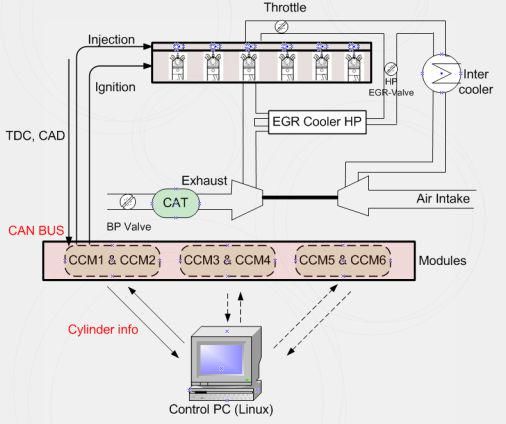
Svenskt Gastekniskt Center AB, Malmö – www.sgc.se 15SGC Rapport 2013:286 2. Experimental setup 2.1 The test engine The project has had an experimental nature. The experimental engine was originally a heavy-duty diesel engine from Volvo Trucks which has been converted for natural gas operation; see Table 1 for engine specification. The engine is equipped with a short-route cooled EGR system and a turbocharger with wastegate. Table 1. Specification of the engine Number of Cylinder 6 Displacement 9,4 Liter Bore 120 mm Stroke 138 mm Compression ratio 10,5 :1 Fuel Natural gas Originally the engine is equipped with a single-point injection system, with four in- jectors at the fuel injector assembly. The single-point injection system was re- placed by a multi-port injection system. The main reasons for using a multi-port injection system are the possibility of adjusting injection for each cylinder individu- ally (i.e. cylinder balancing) and faster response to throttle changes (i.e. better transient capability). The original fuel pressure system supplies gas at a pressure of approximately 10 bar. The test-bench engine is supplied with natural gas at a pressure of 4 bar, thus the port injection system is equipped with 12 injectors (2 per cylinder) to compensate the lower pressure and cover the whole load range, see. This also makes it possible to operate the engine with two different gaseous fuels simultaneously, in case it is desired. Cylinder-individual control of fuel injection and ignition is possible with a new platform developed by Hoerbiger Control Systems. Three Cylinder-Control- Modules (CCM) are designed especially for cylinder-individual control of ignition and fuel injection as well as ion current measurements. The modules use the well- known message-based protocol Control Area Network (CAN) for communication. The engine setup is shown in Figure 1. The three CCMs can be seen below the inlet part and the three boxes on top are ion current modules. 16 Svenskt Gastekniskt Center AB, Malmö – www.sgc.se
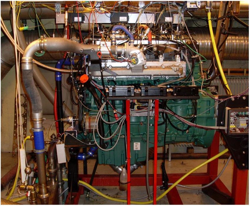
SGC Rapport 2013:286

Figure 1. The experimental engine is connected to a dynamometer.

2.2 The engine control system
A master PC based on GNU/Linux operating system is used as a control system.
The main program is written in C++ which communicates with the three CCMs for
cylinder-individual control of ignition and fuel injection via CAN communication,
see Figure 2. Crank and cam information are used to synchronize the CCMs with
the crank rotation. Flexible controller implementation is achieved using Simulink
and C-code is generated using the automatic code generation tool of Real Time
Workshop. The C-code is then compiled to an executable program which
communicates with the main control program. The program fullfills the
requirements for realtime application.

Svenskt Gastekniskt Center AB, Malmö – www.sgc.se                                   17
SGC Rapport 2013:286

Figure 2. Engine setup structure. A master PC based on GNU/Linux operating
system is used as a control system

2.3 Measurement instruments
Different parameters were measured from the engine. Some of them such as
crank and cam information and throttle position were needed to operate the control
system and the engine. Lots of parameters such as in-cylinder pressure, ion-
current, emissions, torque, different flows and temperatures etc. were measured to
analyze and evaluate the performance of the engine. Data was sampled with dif-
ferent units, data acquisition cards and with different sample resolution. The mas-
ter control PC communicates with two other PCs which sample emissions and
some other parameters (i.e. slow sampled data) via TCP/IP communication proto-
col. Figure 3 shows the data flow and communications between PCs and the en-
gine units.

18                                        Svenskt Gastekniskt Center AB, Malmö – www.sgc.se
SGC Rapport 2013:286

                                                        CCM                      Engine parameters
                             CAN Communication 1        Ignition
                                                        Injection
                                                                                   Crank 3600
                                                                                   CAM,
                                                        EMS2                       Engine speed

                             CAN Communication 2        EGR
                                                                                   HP EGR position

                              Serial Communication             Servo
                                                                                   Throttle

                                                                                   In-cylinder Pressure
                             TC                                     DAQ (Fast)     Ion-Current
                                P-
                                   IP                                              Lambda
                                        Co
                        TC

                                          mm                                       Air-flow
                         P- I

                                            un
                                              ica                                  Inlet pressure
                             P

                                                 tio
                             Co

        Master PC                                   n
                               mm

                                                                                   Temperaturs (exhaust,
       Linux-based                                                                 Water, Oil, ...)
                                 un

                                                                DAQ (Slow)
                                    ica

                                                                                   Other Pressures
                                       t io

                                                                                   Fuel-flow
                                           n

                                                                                   Torque
                                                                DAQ (Slow)         Emissions (NOX, CO,
                                                                                   CO2, HC, ...)

Figure 3     Different parameters were measured from the experimental engine.
These parameters are such as in-cylinder pressure, cam and crank position, EGR
valve position, throttle position, emission, fuel and air flow etc.

The cylinder head is equipped with piezo electric pressure transducers of type
Kistler 7061B to monitor cylinder pressures for heat release calculations. The ion-
currents are sampled by CCMs using the spark plugs as sensors. In-cylinder pres-
sure and ion current data are sampled by a Microstar 5400A (DAP 5400A) data
acquisition processor which is able to measure 1.25 MS/second (with 8 channels)
[8]. To determine the crank shaft position a Leine & Linde encoder is used which
provides five pulses per crank angle degree giving a resolution of 0.2 CAD. The in-
cylinder pressure and ion current data were sampled with a resolution of 0.2 CAD.
Three other parameters, lambda, inlet pressure and air flow were also sampled
with DAP 5400A but with lower resolution. Controlling lambda is one of the objec-
tives of this work; thus fast lambda measurement and fuel calculation is essential.
To measure lambda a broadband sensor from ETAS is used to provide a faster
response than the lambda calculated from exhaust analysis. To measure air flow a
Bronkhorst F-107A is used to provide accurate and fast response data for lambda
control.
   All temperatures were measured by Pentronic Type K thermocouples. Torque is
measured from a load cell and fuel flow was measured by F type Bronkhorst flow-
meter. All these data were sampled by a HP 3852A data acquisition unit which
gives a sample rate of 0.5 Hz. Emissions such as HC, CO, CO2, NO2, NOX and O2
are measured before and after catalyst. Different analyzers were used to measure
the emissions. A summary of the measurement techniques are presented in Table
2.

Svenskt Gastekniskt Center AB, Malmö – www.sgc.se                                                          19
SGC Rapport 2013:286
Table 2. Measurements technique for different emissions
Emission Measurement technique Range
NOX Chemiluminescence Detector (CLD) 0.10000 ppm
HC Flame Ionization Detector (FID) 0-10000 ppm
Non-Dispersive Infrared Detectors
CO2, CO 0-10%,0.16%
(NDIR)
O2 Paramagnetic Detector (PMA) 0-25%
EGR was calculated by measuring CO2 at inlet and exhaust. The latter a
NOX/Oxygen sensor is used to measure oxygen content and the amount of EGR
was estimated based on that.
20 Svenskt Gastekniskt Center AB, Malmö – www.sgc.seSGC Rapport 2013:286
3. Dilution Limit Control
In this chapter an introduction about throttle losses and the effects on part/low load
efficiency is presented. Operating an engine at its maximum dilution limit is sug-
gested as a practical solution to decrease the throttle losses and improve the effi-
ciency. To ensure the combustion stability at these operating conditions robust
control is necessary. Details about the control structure, experiments and the
evaluation of the control performance at steady-state and transient conditions are
reported. Moreover a new method to calculate the combustion stability is devel-
oped and discussed in this chapter.
3.1 Improving Efficiency at Low/Part load
By operating natural gas engines stoichiometrically a three way catalyst can be
used which results in very low emissions however these types of engines suffer
from poor gas-exchange efficiency at part or low loads due to high throttling loss-
es. EGR is a well-known practice to improve engine fuel economy, decrease
knock tendency and reduce raw NOX emissions in certain operating regimes. Us-
ing EGR results in improved fuel economy due to the following facts:
Reduced throttling losses (low/part loads): The addition of inert exhaust gas
into the intake system means that for a given power output, the throttle plate
must be opened further, resulting in increased inlet manifold pressure and
reduced throttling losses (see Figure 4).
Figure 4. Adding EGR means that for a given power output, the throttle plate must
be opened further which results in lower throttle losses
Reduced heat rejection: Lowered peak combustion temperatures not only
reduce NOX formation, it also reduces the loss of thermal energy to com-
bustion chamber surfaces, leaving more energy available for conversion to
mechanical work during the expansion stroke. Increased EGR rate makes
the combustion colder and the combustion duration longer but it can be
compensated somewhat through advanced ignition timing.
Svenskt Gastekniskt Center AB, Malmö – www.sgc.se 21SGC Rapport 2013:286
Reduced chemical dissociation: The lower peak temperature result in more
of the released energy remaining as sensible energy near Top Dead Center
(TDC), rather than being expended (early in the expansion stroke) on the
dissociation of combustion products. This effect is relatively minor com-
pared to the first two.
The experimental engine is a standard production engine and is equipped with a
short route EGR system which is mainly used to suppress knock and not for im-
proving fuel efficiency. When taking into account the advantages of EGR in im-
proving efficiency it is desired to operate the engine at its dilution limit at low/part
load operation regions. The dilution limit is imposed by increased cyclic variation of
the combustion intensity that reduces the drivability. Thus, there will be a limit to
the amount of EGR that can be tolerated for each operating point. However,
closed loop control of EGR based on combustion stability parameters can be a
good means to improve the efficiency and preserve the engines stability at the
same time. On the way to reach this goal different methodologies and combustion
stability parameters are used. Pressure/Ion current based dilution limit control is
applied on the EGR separately in order to maximize EGR rate as while preserving
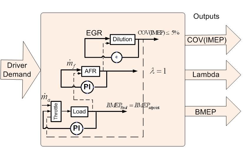
combustion stability. Furthermore, standard closed loop lambda control for control-
ling the overall air/fuel ratio is applied in order to keep the catalyst efficiency at its
highest level all the time.
3.2 Combustion Stability
Different combustion stability parameters can be used to measure the roughness
of the engine operation. In the following subsections a new method for calculating
cyclic variation and combustion stability parameters derived from pressure signals
and Ion current signals are discussed.
3.2.1 Combustion Stability Parameter Based on In-Cylinder Pressure
One important and well-known measure of cyclic variability and combustion stabil-
ity, derived from pressure data, is Coefficient of Variation (COV) of the Indicated
Mean Effective Pressure (IMEP) [9], [10]. It is defined as the standard deviation of
IMEP divided by the mean value based on e.g. 100 cycles. The following equa-
tions express cyclic variations where N is the number of the cycles.
IMEP
COV ( IMEP ) 100 (1)
IMEP
IMEP)2
( IMEP net
COV ( IMEP) N 100
(2)
( IMEP)
3.2.2 New Method for Calculation of Cyclic Variations
Using the traditional method for calculating COV(IMEP) during transient operation
produces erroneous results. A gradual deterministic change in IMEP results in a
22 Svenskt Gastekniskt Center AB, Malmö – www.sgc.seSGC Rapport 2013:286
mean value that is not representative for the entire evaluation interval and the
change in operating point will be interpreted as cyclic variation. This means that
COV calculations based on mean values are not suitable for transient operations.
It is desired to calculate and update the cyclic variations continuously and
smoothly over a fixed number of cycles i.e. 100 cycles. It is also desired to calcu-
late COV(IMEP) in a way that transient operation of the engine does not affect the
calculations too much. To achieve this goal a new method is suggested which up-
date the dataset continuously and uses a sort of low pass filter instead of mean
value in order to eliminate the deterministic errors.
It is assumed that the mean value of IMEP is based on a dataset of 100 cycles
(3). The dataset is desired to be updated continuously. This means that, the vector
of IMEP updates each cycle by replacing the oldest value by the newest one i.e.
IMEP1 is replaced by IMEP101 (4).
[ IMEP1 IMEP2 IMEP3 ... IMEP100 ]
IMEP (3)
100
[ IMEP2 IMEP3 ... IMEP100 IMEP101 ]
IMEPNew (4)
100
During step changes and transients there are still risks to get deterministic chang-
es. The definition of Low-Pass Filter was helpful to calculate a filter set of
COV(IMEP). A new variable is defined and named IMEPfilter and is calculated ac-
cording to (5) where k is the cycle number and λ is a predefined weight that can be
selected between [0 1]. Selecting λ is a trade-off between accuracy and transient
performance. λ was chosen equal to 0.3 in this study. The final expression for cal-
culating the cyclic variation of IMEP is expressed (6).
IMEPfiltered (k 1) m IMEPfiltered (k ) (1 m ) IMEPnet (k )
(5)
( IMEP IMEP 2
filtered )
net
COV ( IMEP ) N 100 (6)
IMEPfiltered
To evaluate the performance of the new method a simulation is performed in Sim-
ulink environment and the filter-based calculation was compared to the mean
based calculation. The comparison is performed in two stages, first under steady-
state condition where the IMEP data are not varied and in the second step a tran-
sient condition is provided by varying IMEP between 5 and 15 bars. The results for
stead-state and transient cases are presented in Figure 5 and Figure 6 respective-
ly. Figure 5 shows that under the steady-state conditions the methods work well
and COV(IMEP) calculations are smooth and reliable. Figure 6 demonstrates
comparison between the two methods under simulated transient conditions. The
figure shows that the filter-based method can easily catch the transient and re-
move the deterministic changes due to the lower weighting on the older IMEP val-
ues. The mean based method is, however, unreliable and cannot be used during
transients.
Svenskt Gastekniskt Center AB, Malmö – www.sgc.se 23SGC Rapport 2013:286
Filter-based method Vs. Cycles @ steady-state condition Filter-based method Vs. Cycles @ Transient condition
COV[%] & IMEP[Bar] 15 20
COV[%] & IMEP[Bar]
COV(IMEP)
15 IMEP
10
COV(IMEP) 10
5 IMEP
5
0 0
0 500 1000 1500 2000 2500 3000 0 500 1000 1500 2000 2500 3000
Cycle number [-] Cycle number [-]
Mean-based method Vs. Cycles @ steady-state condition Mean-based method Vs. Cycles @ Transient condition
15 40
COV[%] & IMEP[Bar]
COV[%] & IMEP[Bar]
COV(IMEP)
30 IMEP
10
COV(IMEP) 20
5 IMEP
10
0 0
0 500 1000 1500 2000 2500 3000 0 500 1000 1500 2000 2500 3000
Cycle number [-] Cycle number [-]
Figure 5. COV(IMEP) calculations with Figure 6. COV(IMEP) calculations with
different methods at steady-state different methods under transient
conditions conditions
3.2.3 Combustion Stability Parameter Based on Ion current Signals
COV(IMEP) is a combustion stability parameter derived from pressure signals.
Direct measurement of in-cylinder pressure can be implemented with pressure
sensors although their use in production vehicles is very expensive, not only in
their capital cost but in their required precision fitting and machining procedures.
The ion current technique is a method of measuring in-cylinder combustion infor-
mation in a non-intrusive and economical manner. A lot of researchers have
shown interest in ion-sensing in recent years concerning measurement techniques
and its possible applications [11], [12], [13], [15], [16]. The following subsections
try to explain very briefly the basics of ion current and finally aim to find a compati-
ble ion current based combustion stability parameter to COV(IMEP). The parame-
ter should be robust enough to be used for diagnostic purposes.
Chemical reactions during the combustion process produce ions and electrons
and the motion of these charged particles can be measured by applying a voltage
( 100 V DC) over the spark plug which is used as an ion sensing probe. One pro-
posal is to divide the ion current into three parts: the ignition phase, the chemical-
ionization phase and the thermal-ionization phase [17]. Figure 7 shows a typical
ion current trace and a pressure signal of an average of 400 cycles from the test
engine. The ignition phase starts with charging the ignition coil and ends with the
coil ringing after the spark. The chemical-ionization phase reflects the early flame
development in the spark gap and thermal-ionization phase appears in the burned
gases behind the flame front. The peak position often appears close to the position
of maximum cylinder pressure.
24 Svenskt Gastekniskt Center AB, Malmö – www.sgc.seSGC Rapport 2013:286
6 4
x 10 Pressure & ION-CURRENT VS. CAD x 10
6 1
Chemi-ionization phase
Thermal-ionization phase
ION-CURRENT [mA]
0.15
4 0
Pressure [Pa]
Ignition phase
2 -1
0 -2
-400 -300 -200 -100 0 100 200 300 400
CAD
Figure 7. Typical Pressure and Ion current signals Vs. Crank Angle Degree (CAD)
In order to find a proper ion current based combustion stability parameter, the be-
havior of the ion current signal at different operating conditions was investigated.
The engine was operated with different air/fuel ratios and different EGR rates.
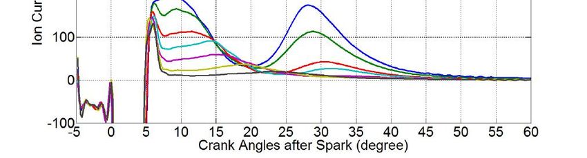
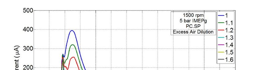
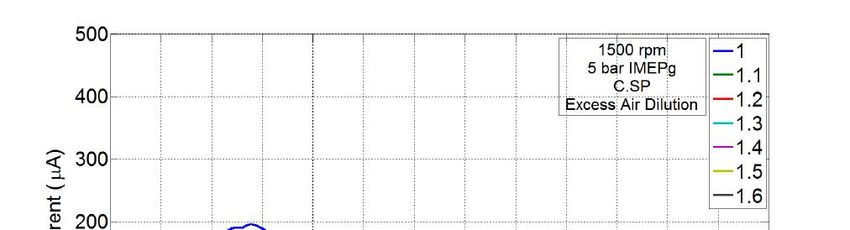
Figure 8 shows ion current signals with different air/fuel ratios. According to the
figure the strongest ion current signal is achieved when operating the engine
somewhat lean (i.e. Lambda =1.1) but as the engine operates leaner or richer the
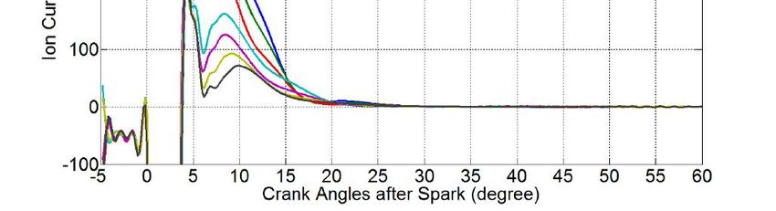
ion current amplitude decreases. Figure 9 shows the ion current signal behavior
with different amounts of EGR. By increasing the EGR rate the amplitudes of the
first and the second peaks decrease. This effect is strongest on the second peak
which almost disappears at highly diluted operating conditions. The ion current
signal is highly depended on the combustion temperature i.e. the colder the com-
bustion the weaker the ion current signal.
Ion-Current Signals with different Vs. CAD Ion-Current signals with different EGR Rate Vs. CAD
2500
3000
=0.9 EGR 0%
2500 =0.95 EGR 10%
2000
Ion-Current Signals [mV]
=1
Ion-Current Signals [mV]
2000 EGR 15%
=1.05
EGR 20%
1500 =1.1 1500
= 1.15
1000
=1.2
500 1000
=1.3
0
500
-500
-1000 0
-1500
-2000 -500
-40 -20 0 20 40 60
CAD [Degree] -40 -20 0 20 40
CAD
Figure 8. Ion current signal decreases Figure 9. Ion current signal decreases
when operating the engine too rich or when increasing the amount of EGR
lean
For combustion diagnostic purposes, reliable signals and parameters are require-
ments. It is demonstrated in Figure 8 and Figure 9 that the signals from the first
and the second peak (especially second peak) becomes very weak as the com-
Svenskt Gastekniskt Center AB, Malmö – www.sgc.se 25SGC Rapport 2013:286
bustion becomes colder. For this reason, the information from the peaks may not
be robust enough for diagnostic purposes especially during very lean or diluted
operation. However, the area created by the first and the second peak contains
useful and reliable information even at low combustion temperature that can be
used for combustion diagnostic and control purposes. The area under the first and
second peak can be expressed as a new parameter as in (7) where ܷ (ߠ) is the
voltage produced by the ion current interface. The ion-integral limits ߠଵand ߠଶmust
be chosen so that the ignition phase is not a part of the integral and also such that
it includes the entire first and the second peaks (see Figure 10).
2
Ion Integral
1
U ion ( )d (7)
1500
Ion-Integral
1000
ION-CURRENT [mA]
500
0
2
1
-500
-30 -20 -10 0 10 20 30 40
CAD
Figure 10. Ion-integral includes both the first and the second peak of the ion
current signals
An experiment according to Table 3 is performed. The aim of this experiment is to
find out if there is any correlation between COV(ion-integral) and COV(IMEP).
Table 3. Test matrix to capture the correlation between COV(Ion-Integral) and
COV(IMEP)
Speed (RPM) EGR Rate (%)
800 0-4-8-10-12-15
1000 0-4-8-10-12-15-20
1200 0-4-8-10-12-15-20
1400 0-4-8-10-12-15-20
To compute the cyclic variation 100 cycles of the data were used. Figure 11 shows
COV(ion-integral) correlation with COV(IMEP). It can be seen that COV(ion-
integral) depends linearly on COV(IMEP) with different slopes at different engine
speeds. Figure 11 also shows that the level of COV(ion-integral) is much higher
26 Svenskt Gastekniskt Center AB, Malmö – www.sgc.seYou can also read