The Málaga Platform (Release B) - Deliverable D4.5
←
→
Page content transcription
If your browser does not render page correctly, please read the page content below
5GENESIS                                          D4.5 • Málaga Platform Release B

Deliverable D4.5

The Málaga Platform (Release B)

           Editor I. González (UMA), P. Merino (UMA), A. Ríos (UMA)

  Contributors Universidad de Malaga, Airbus, Telefónica I+D,
               Nemergent, Athonet, Eurecom, Atos, RunEl,
               Ayuntamiento de Málaga, Fogus, Cosmote

       Version 1.0

            Date January 31st, 2020

   Distribution PUBLIC (PU)

© 5GENESIS Consortium
                                                                              Page 1 of 79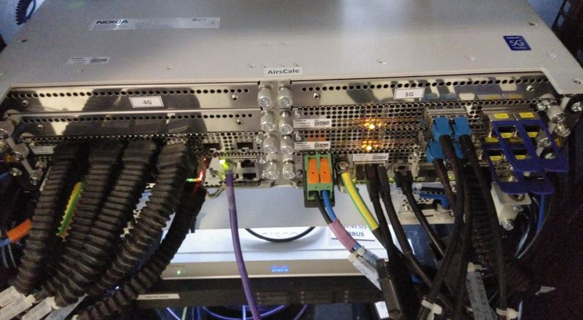
5GENESIS                                                     D4.5 • Málaga Platform Release B

List of Authors
ADS                 AIRBUS DS SLC
Arthur Lallet
ATH                 ATHONET SRL
Daniele Munaretto, Fabio Giust
ATOS                ATOS SPAIN SLC
Elisa Jimeno, Javier Melian, Sonia Castro
COS                COSMOTE KINITES TILEPIKOINONIES AE
Fofy Setaki
ECM                 EURECOM
Florian Kaltenberger, Panagiotis Matzakos
FOGUS               Fogus Innovations & Services
Dimitris Tsolkas
MoM                 Ayuntamiento de Málaga
Ricardo Fernández, José Manuel Moreno
NEM                 NEMERGENT SOLUTIONS SL
Eneko Atxutegi, Egoitz Alonso, Leire Eguia
REL                 RUNEL NGMT LTD
Israel Koffman
TID                 TELEFóNICA INVESTIGACIÓN Y DESSARROLLO S.A.u.
David Artuñedo, Daniel García, Alberto Flórez
UMA                 Universidad de Málaga
Pedro Merino, Álvaro Ríos, Bruno García, Almudena Díaz, Iván González, Francisco Luque, María del
Mar Moreno

© 5GENESIS Consortium
                                                                                             Page 2 of 79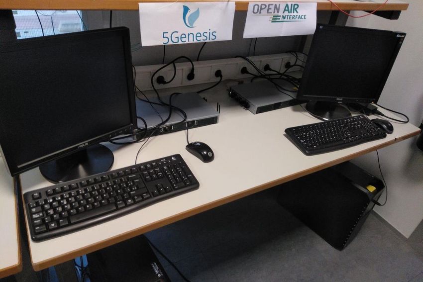
5GENESIS                                                     D4.5 • Málaga Platform Release B

Disclaimer
The information, documentation and figures available in this deliverable are written by the
5GENESIS Consortium partners under EC co-financing (project H2020-ICT-815178) and do not
necessarily reflect the view of the European Commission.
The information in this document is provided “as is”, and no guarantee or warranty is given
that the information is fit for any particular purpose. The reader uses the information at his/her
sole risk and liability.

© 5GENESIS Consortium
                                                                                            Page 3 of 79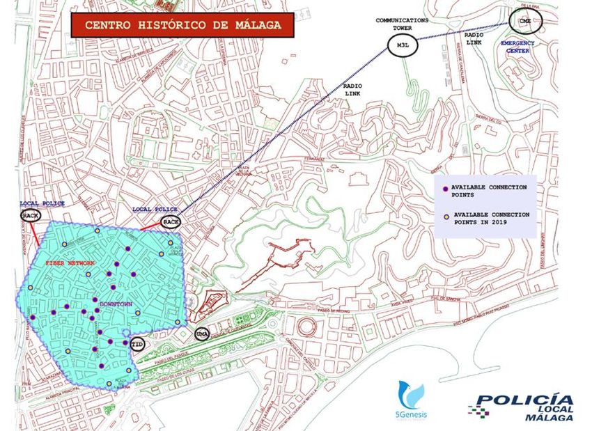
5GENESIS                                                 D4.5 • Málaga Platform Release B

Copyright
  Copyright © 2020 the 5GENESIS Consortium. All rights reserved.
  The 5GENESIS Consortium consists of:
NATIONAL CENTER FOR SCIENTIFIC RESEARCH “DEMOKRITOS”                         Greece
AIRBUS DS SLC                                                                France
ATHONET SRL                                                                  Italy
ATOS SPAIN SA                                                                Spain
AVANTI HYLAS 2 CYPRUS LIMITED                                                Cyprus
AYUNTAMIENTO DE MALAGA                                                       Spain
COSMOTE KINITES TILEPIKOINONIES AE                                           Greece
EURECOM                                                                      France
FOGUS INNOVATIONS & SERVICES P.C.                                            Greece
FON TECHNOLOGY SL                                                            Spain
FRAUNHOFER GESELLSCHAFT ZUR FOERDERUNG DER ANGEWANDTEN FORSCHUNG
                                                                             Germany
E.V.
IHP GMBH – INNOVATIONS FOR HIGH PERFORMANCE MICROELECTRONICS/LEIBNIZ-
                                                                             Germany
INSTITUT FUER INNOVATIVE MIKROELEKTRONIK
INFOLYSIS P.C.                                                               Greece
INSTITUTO DE TELECOMUNICACOES                                                Portugal
INTEL DEUTSCHLAND GMBH                                                       Germany
KARLSTADS UNIVERSITET                                                        Sweden
L.M. ERICSSON LIMITED                                                        Ireland
MARAN (UK) LIMITED                                                           UK
MUNICIPALITY OF EGALEO                                                       Greece
NEMERGENT SOLUTIONS S.L.                                                     Spain
ONEACCESS                                                                    France
PRIMETEL PLC                                                                 Cyprus
RUNEL NGMT LTD                                                               Israel
SIMULA RESEARCH LABORATORY AS                                                Norway
SPACE HELLAS (CYPRUS) LTD                                                    Cyprus
TELEFONICA INVESTIGACION Y DESARROLLO SA                                     Spain
UNIVERSIDAD DE MALAGA                                                        Spain
UNIVERSITAT POLITECNICA DE VALENCIA                                          Spain
UNIVERSITY OF SURREY                                                         UK

This document may not be copied, reproduced or modified in whole or in part for any purpose
without written permission from the 5GENESIS Consortium. In addition to such written
permission to copy, reproduce or modify this document in whole or part, an acknowledgement
of the authors of the document and all applicable portions of the copyright notice must be
clearly referenced.

© 5GENESIS Consortium
                                                                                        Page 4 of 79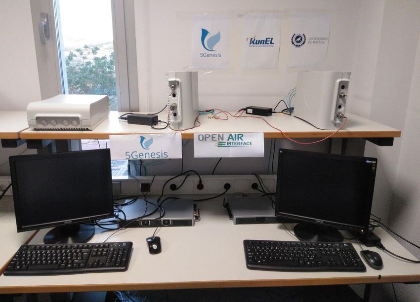
5GENESIS                              D4.5 • Málaga Platform Release B

Version History
Rev. N     Description       Author                         Date
1.0        Release of D4.5   ALL                            31/01/20

© 5GENESIS Consortium
                                                                   Page 5 of 79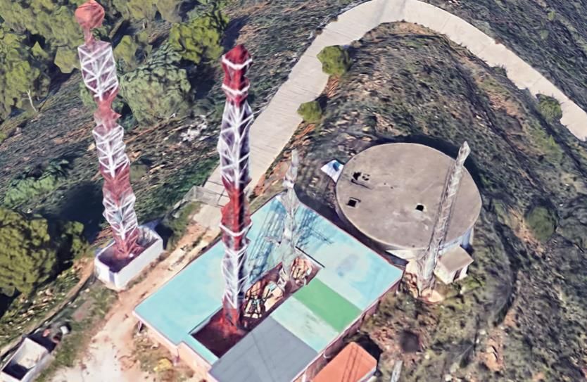
5GENESIS                                                D4.5 • Málaga Platform Release B

LIST OF ACRONYMS
Acronym                 Meaning
3GPP                    3rd Generation Partnership Project
ANDSF                   Access Network Discovery and Selection Function
API                     Application Programming Interface
AS                      Application Server/Service
CA                      Consortium Agreement
CME                     City Emergency Center
CORD                    Central Office Rearchitected as Data Center
DHCP                    Dynamic Host Configuration Protocol
DUT                     Device Under Test
E2E                     End to End
ELCM                    Experiment Life-Cycle Manager
eMBMS                   Evolved Multimedia Broadcast Multicast Service
EMS                     Element Management System
EPC                     Evolved Packet Core
ePDG                    Evolved Packet Data Gateway
FCAPS                   Fault, Configuration, Accounting, Performance and Security
GA                      Grant Agreement
GUI                     Graphical User Interface
HSS                     Home Subscriber Server
IMS                     IP Multimedia Subsystem
KPI                     Key Performance Indicator
LTE                     Long Term Evolution
MANO                    Management and Orchestration
MCPTT                   Mission Critical Push-to-Talk
MCS                     Mission Critical Cervices
MME                     Mobility Management Entity
MNO                     Mobile Network Operator
MOCN                    Multiple Operator Core Network
NFV                     Network Function Virtualization
NFVI                    Network Function Virtualization Infrastructure
NFVO                    Network Function Virtualization Orchestrator

© 5GENESIS Consortium
                                                                                     Page 6 of 79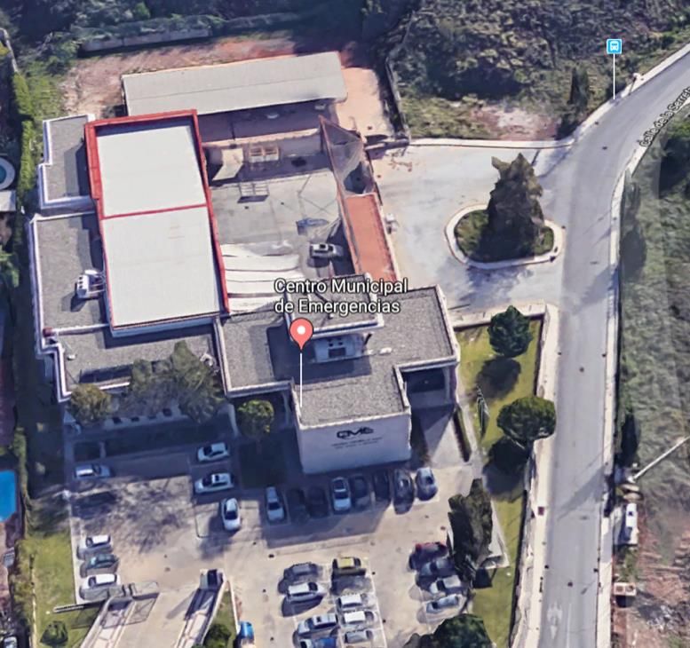
5GENESIS                                               D4.5 • Málaga Platform Release B

NMS                     Network Management System
NSA                     Non-StandAlone
OAI                     OpenAirInterface
OAM                     Operations, Administration and Management
OLT                     Optical Line Termination
OSM                     Open Source MANO
OSS/BSS                 Operations Support System and Bussiness Support System
OTT                     Over The Top
PCRF                    Policy and Charging Rules Function
PGW                     Packet Gateway
PNF                     Physical Network Function
PoP                     Point of Presence
QCI                     QoS Class Identifier
QoS                     Quality of Service
RAN                     Radio Access Network
RRH                     Remote Radio Head
SCPI                    Standard Commands for Programmable Instruments
SDK                     Software Development Kit
SDN                     Software Defined Network
SDR                     Software Defined Radio
SGW                     Serving Gateway
SNMP                    Simple Network Management Protocol
SoC                     System on a Chip
SON                     Self-Organized Network
TAP                     Test Automation Platform
UE                      User Equipment
VIM                     Virtualization Infrastructure Manager
VLAN                    Virtual Local Area Network
VNF                     Virtualized Network Function
WAN                     Wide Area Network
WIM                     WAN Infrastructure Manager
X-PON                   Any PON technology (G-PON, XGS-PON, NGPON2)

© 5GENESIS Consortium
                                                                                   Page 7 of 79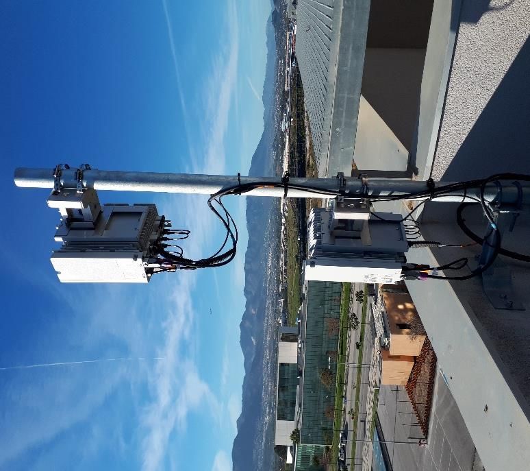
5GENESIS                                                      D4.5 • Málaga Platform Release B

Executive Summary
5GENESIS project is building a 5G experimentation facility composed of six 5G platforms,
distributed in Europe, with the major task of validating the 5G KPIs (Key Performance
Indicators) defined by the 5G PPP1. The five main platforms are being developed in Athens,
Berlin, Limassol, Málaga and Surrey, while the sixth one serves as a portable demonstrator. All
of them are instances of a common reference architecture already defined in deliverable D2.2
“Initial overall facility design and specifications” in response to the project requirements,
identified in deliverable D2.1 “Requirements of the facility”. This deliverable focuses on the
specific instantiation of the reference architecture of the 5GENESIS Málaga Platform. It first
presents the platform instantiation as expected to be by the end of the project and then reports
the current status (platform release B), resulted after the second integration cycle of the project
(December 2019).
The 5GENESIS project is split into three integration cycles, each one lasting 6 months and
followed by a testing cycle of 3 months. The platform result of an integration cycle is called a
platform Release, named Release A, B and C for each integration cycle. Integration cycles are
also named as phases, namely Phase 1, 2 and 3.
The main challenge of the Málaga site2 is to build a 5G multi-technology, multi-domain End-to-
End (E2E) platform that will be used to validate the 5G PPP KPIs for 3GPP Mission Critical
Services (MCS) offered over E2E network slices. The main technologies combined for that are
the 5G New Radio (NR), the edge computing at the Radio Access Network (RAN) and the flexible
orchestration of network functions and services at the core of the network.
The 5GENESIS Málaga Platform is being deployed in two main areas of the city of Málaga: the
campus of the University of Málaga (UMA), nearby the research Building Ada Byron; and the
old historical center of the city, where the Police Department operates a number of surveillance
cameras. Additionally, the City Emergency Center (CME), where those cameras are monitored,
will serve as a support site for the platform. The sites are directly connected to the main data
center and the core network at the UMA research building Ada Byron. Additional connections
with the premises of a commercial Mobile Network Operator (MNO) in Madrid and with the
5GENESIS Athens platform through GÉANT are planned. The first one will allow to share the
MNO network in the city centre with the Málaga Platform, while the second will allow the
testing of two 5GENESIS platforms interconnected.
For the delivery of the release B of the platform, the integration of several infrastructure
components located in the above-mentioned sites was required. All these integration activities
are described in this document. The integration of the Coordination Layer, defined in
deliverable D2.2, is described in detail, as it realises control and monitoring aspects that are
necessary in order to automate the process of the experimentation, measure KPIs and
implement full control and security aspects. One step beyond the individual description of the
components developed in WP3 for all the platforms, the document includes technical
characteristics and development choices specific to the Málaga Platform.

1
    https://5g-ppp.eu/kpis/
2
    https://5genesis.eu/malaga-platform/

© 5GENESIS Consortium
                                                                                             Page 8 of 79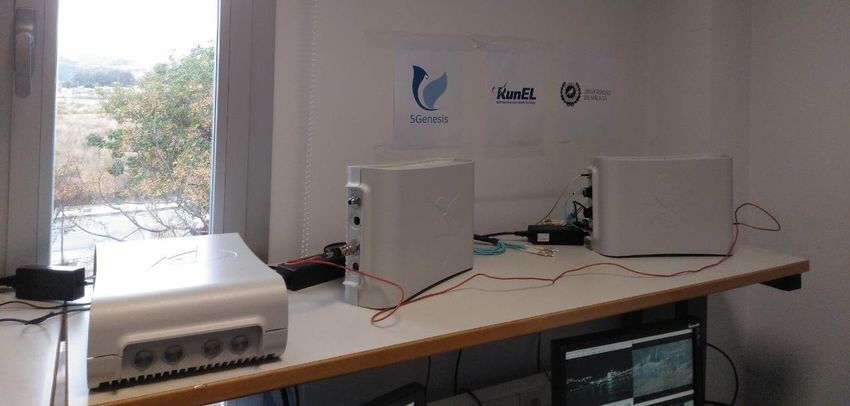
5GENESIS                                                    D4.5 • Málaga Platform Release B

The expected deployments and extensions for the support of experimentation use cases in big
events are provided, serving as a reference point for the evolution of the Malaga Platform. The
major target is Phase 3, when the Platform will be able to support trials related to MCS in which
verticals and real end users will be involved.

© 5GENESIS Consortium
                                                                                           Page 9 of 79
5GENESIS                                                                              D4.5 • Málaga Platform Release B

Table of Contents
LIST OF ACRONYMS .............................................................................................................. 6
1. INTRODUCTION .............................................................................................................. 15
         Purpose of the document .............................................................................................. 15
         Structure of the document ............................................................................................ 16
         Target Audience............................................................................................................. 16
2. MALAGA PLATFORM OVERVIEW ..................................................................................... 18
         Platform Sites Overview................................................................................................. 19
      2.1.1. Overview ................................................................................................................. 19
      2.1.2. Site 1: Indoor UMA Lab ........................................................................................... 20
      2.1.3. Site 2: UMA Outdoor deployment .......................................................................... 22
      2.1.4. Site 3: Málaga City Centre....................................................................................... 22
      2.1.5. Site 4: Málaga Police Emergency Centre ................................................................ 23
      2.1.6. Site 5: Telefonica I+D lab in Málaga/Madrid ........................................................... 24
         Target Deployment Topology ........................................................................................ 25
      2.2.1. Infrastructure Layer ................................................................................................ 26
          2.2.1.1. Main Data Center............................................................................................. 27
          2.2.1.2. Edge Data Center ............................................................................................. 27
          2.2.1.3. Mobile Network Technology............................................................................ 28
      2.2.2. Management and Orchestration Layer ................................................................... 36
          2.2.2.1. NFV Management & Orchestration ................................................................. 38
          2.2.2.2. Slice Manager .................................................................................................. 39
          2.2.2.3. Element Management Systems ....................................................................... 39
          2.2.2.4. Network Management Systems....................................................................... 40
      2.2.3. Coordination layer .................................................................................................. 41
          2.2.3.1. Monitoring & Measurements .......................................................................... 41
3. EVOLUTION OF THE MALAGA PLATFORM .......................................................................... 43
         Phase 2 Instantiation of the 5GENESIS architecture ...................................................... 43
         Phase 1 Accomplishments ............................................................................................. 46
         Phase 2 Accomplishments ............................................................................................. 47
      3.3.1. Infrastructure layer Accomplishment ..................................................................... 48
      3.3.2. Management and Orchestration layer Accomplishment ........................................ 50
      3.3.3. Coordination layer Accomplishment ...................................................................... 50

© 5GENESIS Consortium
                                                                                                                                 Page 10 of 79
5GENESIS D4.5 • Málaga Platform Release B
Next milestones ............................................................................................................. 51
4. MALAGA USE CASE-SPECIFIC EXTENSIONS ........................................................................ 52
Use Cases Target Deployment ....................................................................................... 52
4.1.1. Use case 1 – Wireless Video in Large Scale Event................................................... 52
4.1.1.1. Use Case 1 Components and Technology ........................................................ 52
4.1.1.2. Use Case 1 Topology and Architecture ............................................................ 53
4.1.2. Use Case 2 – Multimedia Mission Critical Services ................................................. 55
4.1.2.1. Use Case 2 Components and Technology ........................................................ 55
4.1.2.2. Infrastructure components .............................................................................. 55
4.1.2.3. Client components ........................................................................................... 56
4.1.2.4. Use Case 2 Topology and Architecture ............................................................ 57
4.1.3. Use case 3 – Edge-based Mission critical services .................................................. 59
4.1.3.1. Use Case 3 Components and Technology ........................................................ 59
4.1.3.2. Server-side ....................................................................................................... 59
4.1.3.3. Client-side ........................................................................................................ 61
4.1.3.4. Use case 3 Topology and Architecture ............................................................ 62
Use Cases Phase 1 Accomplishments ............................................................................ 63
Use Cases Phase 2 Accomplishments ............................................................................ 64
Use Cases Next Milestones ............................................................................................ 64
5. CONCLUSIONS ............................................................................................................... 66
REFERENCES...................................................................................................................... 67
6. APPENDIX 1: MALAGA PLATFORM COMPONENTS AND ARCHITECTURE DETAILS ....................... 69
Main Data Center........................................................................................................... 69
Edge Data Center ........................................................................................................... 70
Mobile Core Network .................................................................................................... 73
6.3.1. Athonet Mobile Core .............................................................................................. 73
6.3.2. Polaris LTE NetEPC .................................................................................................. 73
Indoor Radio Access Network ........................................................................................ 74
6.4.1. OpenAirInterface 5G ............................................................................................... 74
6.4.2. RunEL 5G................................................................................................................. 76
UMA outdoor Radio Access Network ............................................................................ 77
MoM outdoor Radio Access Network ............................................................................ 78
© 5GENESIS Consortium
Page 11 of 795GENESIS D4.5 • Málaga Platform Release B
List of Figures
Figure 1: Picture of 5GENESIS Málaga Deployment ............................................................................ 18
Figure 2: High-level Overview of the different Málaga Platform Sites ................................................... 19
Figure 3: UMA Lab Testbed Components ............................................................................................. 20
Figure 4: Part of Indoor UMA Testbed .................................................................................................. 21
Figure 5: 5G setups at UMA Testbed .................................................................................................... 21
Figure 6: UMA Outdoor Testbed and Ada Byron building location ....................................................... 22
Figure 7: Area of Málaga City Centre with locations for Small Cells ..................................................... 23
Figure 8: Málaga Emergency Centre .................................................................................................... 23
Figure 9: Radio Link Repeater close to Emergency Centre .................................................................. 24
Figure 10: 5Tonic Lab deployment ........................................................................................................ 25
Figure 11: Overview of the Málaga Platform Infrastructure ................................................................... 26
Figure 12: Edge Overview ..................................................................................................................... 28
Figure 13: Conformance Testing Equipment available in the Málaga Platform .................................... 31
Figure 14: FlexiBTS Nokia 4G Small Cell ............................................................................................. 32
Figure 15: OpenAirInterface setup 3 at Málaga Platform ...................................................................... 32
Figure 16: RunEL setup 4 at Málaga Platform ...................................................................................... 33
Figure 17: RunEL 5G setup architecture ............................................................................................... 33
Figure 18: Nokia 5G and 4G micro RRH in Ada Byron building rooftop ............................................... 34
Figure 19: Nokia Airscale BBU at Ada Byron site ................................................................................. 35
Figure 20: Core NFVI and Edge Composition ....................................................................................... 38
Figure 21: Functional Architecture of Self-functions ............................................................................. 39
Figure 22: The Málaga Platform Evolution based on 5GENESIS Reference Architecture ................... 43
Figure 23: OAI noS1 mode architecture supporting IP traffic flow ........................................................ 49
Figure 24: IDIS video camera ................................................................................................................ 53
Figure 25: IDIS Center management software ...................................................................................... 53
Figure 26: Use case 1 Final Deployment .............................................................................................. 54
Figure 27: Use Case 1 outdoor experiment setup ................................................................................ 54
Figure 28: Samsung Galaxy S8 running the MCS Client Application ................................................... 56
Figure 29: The Airbus Tactilon Dabat Device running the MCS Client Application .............................. 57
Figure 30: Use Case 2 Deployment for release B ................................................................................. 58
Figure 31: Target Use Case 2 Deployment for the Final Release ........................................................ 59
Figure 32: Simplified Users and Groups Management OAM GUI ......................................................... 60
Figure 33: MCPTT/MCS Basic Components and Integration Interface ................................................ 61
Figure 34: MCS Client Building Blocks .................................................................................................. 62
Figure 35: Release A - Use Case 3 Indoor Deployment ....................................................................... 63
Figure 36: Advanced Use Case 3 Deployment ..................................................................................... 63
Figure 37: NFVI Deployment ................................................................................................................. 70
© 5GENESIS Consortium
Page 12 of 795GENESIS D4.5 • Málaga Platform Release B
Figure 38: Edge Management Network ................................................................................................. 71
Figure 39: Edge Service Network .......................................................................................................... 72
Figure 40: Edge Infrastructure Physical Layout .................................................................................... 72
Figure 41: 5G-NR UE Platform running OpenAirInterface .................................................................... 74
Figure 42: USRP N310 .......................................................................................................................... 75
Figure 43: UMA Indoor OAI 5G Deployment ......................................................................................... 76
Figure 44: University of Málaga Outdoor Deployment Infrastructure .................................................... 78
Figure 45: Police of Málaga Outdoor Deployment Infrastructure .......................................................... 79
© 5GENESIS Consortium
Page 13 of 795GENESIS D4.5 • Málaga Platform Release B
List of Tables
Table 1: Dependencies with previous 5GENESIS documents .............................................................. 15
Table 2: Infrastructure Layer Technologies ........................................................................................... 26
Table 3: 5GENESIS Málaga Platform 5G Technology and roadmap ................................................... 29
Table 4: Málaga Platform radio access equipment deployed ............................................................... 31
Table 5: Monitoring and Management Tools ......................................................................................... 36
Table 6: Coordination Tools .................................................................................................................. 41
Table 7: Deployed LTE setups detail .................................................................................................... 44
Table 8: Deployed 5G setups detail ...................................................................................................... 45
Table 9: Summary of Málaga Platform Release B accomplishments ................................................... 47
Table 10: Main Data Center servers ..................................................................................................... 69
Table 11: Part Items of 5G-NR UE Platform ......................................................................................... 75
© 5GENESIS Consortium
Page 14 of 795GENESIS D4.5 • Málaga Platform Release B
1. INTRODUCTION
Purpose of the document
This deliverable provides a detailed description of the layout and functionalities of the 5G
experimental platform being built in the city of Málaga in the context of the H2020 project
5GENESIS. The project aims to validate the relevant 5G PPP KPIs over realistic 5G platforms and
use cases. In previous deliverables, the project identified the specific requirements [1] to be
satisfied by each of the platforms that compose the facility and its common reference
architecture [13].
The document is the second of a series of three deliverables which main goal is to report on
the status of the 5GENESIS Málaga Platform, in line with the three experimentation cycles
defined in the project: April-June 2019, January-March 2020, October 2020-June 2021. These
experimentation cycles target the validation of relevant 5G KPIs in a full end-to-end network
and follow an integration cycle where new or upgraded components are integrated into the
platform.
The following table shows the set of deliverables with which the present one shares
dependence. It is advisable to check them to better understand the Málaga Platform status and
evolution.
Table 1: Dependencies with previous 5GENESIS documents
id Document Title Relevance
The document establish the ground for the first set of
D2.1 Requirements of the
requirements to be supported by the testbed for the
[1] Facility
realisation of the planned Use Cases.
The 5GENESIS facility architecture is defined in this
D2.2 5GENESIS Overall Facility
document. The list of functional components to be deployed
[2] Design and Specifications
in each testbed is defined.
D2.3 Initial planning of tests Testing and experimentation specifications that influence the
[3] and experimentation testbed definition, operation and maintenance are defined.
Management and The document presents the MANO solutions that are
D3.1
orchestration (Release integrated in the infrastructure. Interfaces and
[4]
A) deployment options are also described.
D3.3 Slice management WP3 The document details the Slice Manager solution, its
[5] (Release A) interfaces towards the MANO and NMS components.
Monitoring and WP3 The document details the Infrastructure Monitoring
D3.5 analytics (Release A) components and the interfaces with infrastructure
[6]
elements.
The document details the 5G Core network functions
D3.9 5G Core Network WP3
and provides input on their integration with the
[7] Functions (Release A)
infrastructure and management components.
© 5GENESIS Consortium
Page 15 of 795GENESIS D4.5 • Málaga Platform Release B
5G Access Components
D3.11 The document details the 5G Radio Access components
and User Equipment
[8] and UE devices.
(Release A)
D4.4 The Málaga Platform This document summarizes the sites and components that
[9] (Release A) will form the Málaga Platform and sets the ground for D4.5.
D5.1 System-level tests and Midterm report with detailed analysis of the results from the
[10] verification (Release A) system-level tests and the verification trials.
This deliverable includes the trials and experimentation
D6.1 Trials and
executed on the 5GENESIS platform as well as the initial
[11] experimentation - cycle 1
results of the first integration cycle.
Structure of the document
The technical part of the document starts in Section 2. In the first subsection of Section 2, an
overview of the sites that host the components of the Málaga Platform is provided. Then, the
second subsection depicts the overall architecture of the platform in detail, splitting the
characterization of the components in three logical layers, as per defined in the reference
architecture:
• The Coordination Layer is the high-level component responsible for the synchronization
of the rest of the elements including the monitoring tools of the platform.
• The Management and Orchestration (MANO) layer controls the configuration of the
physical and logical elements of the setup and is responsible for the creation and
management of the different slices.
• The low-level Infrastructure Layer is composed of all the physical components that
provide service to the entire platform.
As a complement to Section 2, Appendix 1 includes the setup and the connections of the
different subsystems that compose the platform, covering aspects that range from the indoor
deployment of base stations inside the laboratory of the University of Málaga to the
interconnection between the police cameras used in the use-cases through a commercial MNO
network. Appendix 1 can be used as a reference point for those interested in the technical
details of the components of the Málaga Platform.
Section 3 includes a description of the intended evolution of the platform in consecutive cycles,
listing the current accomplishments and the milestones to reach in the deployment of the
Release C.
Finally, Section 4 is devoted to the three use cases that will be tested in the final release of the
platform, describing their components, the scenarios of utilization and the expected outcome.
Target Audience
This deliverable detailing the Release B of the Málaga Platform is the first public document
depicting the platform status and the integration activities that took place until the present
date. The target audience includes the European Commission and the general audience
© 5GENESIS Consortium
Page 16 of 795GENESIS D4.5 • Málaga Platform Release B
interested in the Málaga Platform for experimentation, as well as the 5GENESIS consortium
itself.
This document will ease the task of the European Commission of evaluating the progress of the
developments carried on in the platform, as its current scope and status, and its evolution from
the last release. It will also allow the general public to understand what the platform offers and
its possibilities in relation with 5G-oriented experimentation. Finally, the deliverable will be also
helpful for the 5GENESIS project partners, since it will provide valuable inputs for analysis and
decision making in relation with future developments, integration, experiments, requirements,
and, in general, for improving the roadmap of this platform specifically and of the 5GENESIS
framework as a whole.
© 5GENESIS Consortium
Page 17 of 795GENESIS D4.5 • Málaga Platform Release B
2. MALAGA PLATFORM OVERVIEW
The 5GENESIS Málaga Platform is an extension of the previous 4G platform deployed at UMA
and result of other European projects like FLEX, Fed4Fire, Fed4Fire+, TRIANGLE, Q4Health and
NRG5. The latest instance of this previous platform is the testbed TRIANGLE3, which became a
platform for validation of KPIs of devices and applications over mobile networks. The TRIANGLE
testbed has been the starting point for the 5GENESIS Málaga Platform development.
The new platform in 5GENESIS is composed of the resources coming mainly from UMA,
Telefonica I+D, Police Department of Málaga City, ATOS, Athonet, RunEL and Eurecom. The
platform is oriented to validate KPIs for verticals related to Mission Critical Communications,
which require Enhanced Mobile Broadband and Low Latency Communications, and that are
supported by Airbus and Nemergent in the context of 5GENESIS. The platform combines: a) the
current indoor UMA instances of TRIANGLE testbed (one of the EU FIRE research testbeds,
located in Ada Byron Research building); b) one outdoor deployment at the UMA campus); c)
an outdoor deployment in the city centre of Málaga; d) Telefonica mCORD infrastructure to be
deployed in Málaga; e) the orchestration solution provided by ATOS; and f) Athonet VNFs for
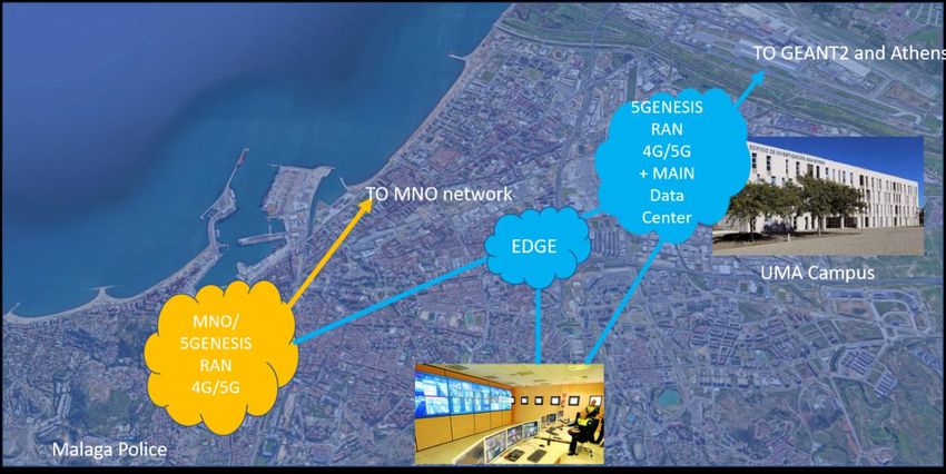
LTE and 5G core network. Figure 1 depicts the main sites of the platform and how the major
components are deployed in the field.
Figure 1: Picture of 5GENESIS Málaga Deployment
There are also plans to interconnect Málaga and Athens platforms for integration and
connectivity experimentation purposes. A high capacity link from the Géant network will be
used for this. The following figure shows a high-level overview of the whole network that will
be implemented in the Málaga Platform by the end of the project.
3
https:// www.triangle-project.eu
© 5GENESIS Consortium
Page 18 of 795GENESIS D4.5 • Málaga Platform Release B
Figure 2: High-level Overview of the different Málaga Platform Sites
The interconnection between the different sites of the platform will be done using optic fiber
links. The physical fibers are already installed between the cameras´ locations and the Police
Control Center. From it, a connection with the MNO premises will be installed in order to split
the commercial users from the experimental 5GENESIS ones using the same spectrum. The
5GENESIS users´ traffic will be routed to the Ada Byron building, where the core network is
located. The user´s traffic will be then routed back to the Málaga City Centre and to the Police
Control Center using a radio link between the two locations.
Platform Sites Overview
2.1.1. Overview
The Málaga Platform of 5GENESIS facility is physically distributed in three different locations,
belonging to three different domains of the network:
• Ada Byron Research building hosts the core network and most of the equipment
(OpenStack deployment, Edge infrastructure, experimental 5G radio) as well as part of
the commercial 5G base stations of the platform.
• Málaga city centre, where the Police cameras to be used are already available. In
collaboration with Telefonica, additional 5G cells will be installed in a hybrid
commercial/experimental deployment. The police facilities across the city centre, which
host wiring and other equipment, will also serve as a connection point between the
cameras, the base stations and the MNO and the University network.
• The City Emergency Center, located on the outskirts of the city and connected through
a fixed radio link with the police facilities, will take the role of the remote end-user that
consumes the video from the cameras and assesses the performance of the entire
platform in a real world public safety environment.
© 5GENESIS Consortium
Page 19 of 795GENESIS D4.5 • Málaga Platform Release B
Additionally, commercial UEs in the city centre are connected to premises of the MNO in
Madrid, as explained in the following section 2.1.6. This also allows the evaluation of the impact
of Edge infrastructure on the network.
A brief description of the sites involved in Málaga Platform follows. Specific diagrams detailing
the architecture of all the sites and the setups, along with Main Data Center and Edge Data
Center diagrams, can be seen in Appendix 1.
2.1.2. Site 1: Indoor UMA Lab
The MORSE research group of Universidad de Málaga operates the TRIANGLE testbed, which is
the result of the H2020 project TRIANGLE. TRIANGLE testbed was one of the examples
considered as 5G European platforms in the 5G-PPP Trials Roadmap Version 2.04. The testbed
offers a realistic experimentation environment covering LTE, LTE-A and 5G features, and it is
based on commercial off-the-shelf solutions (both in the radio and core network), software
defined radio equipment and conformance testing equipment.
Figure 3: UMA Lab Testbed Components
Figure 3 depicts the different components of the testbed per category, whereas Figure 4 shows
part of the actual indoor laboratory. Details regarding the equipment currently available are
provided in Section 2.2.1.
4
https://5g-ppp.eu/5g-trials-roadmap/
© 5GENESIS Consortium
Page 20 of 795GENESIS D4.5 • Málaga Platform Release B
Figure 4: Part of Indoor UMA Testbed
Besides the TRIANGLE testbed components, Málaga Platform also integrates 5G NR radio
access equipment, 5G compatible UEs, 5G NSA compatible EPC and different services to
support the use cases. This components will be described accordingly in section 2.2. Some of
them can be seen in Figure 5.
Figure 5: 5G setups at UMA Testbed
© 5GENESIS Consortium
Page 21 of 795GENESIS D4.5 • Málaga Platform Release B
2.1.3. Site 2: UMA Outdoor deployment
UMA has extended the indoor lab to cover an outdoor area around the Ada Byron research
building as represented in Figure 6. A further extension might be considered during the project
lifetime if it is required from external verticals using the platform. The current extension has
consisted in the deployment of small cells or remote heads (RRH) with the latest radio release
available. Such equipment has been provided by vendors through a public procurement
launched by UMA, including both 5GENESIS and UMA specific budget. The spectrum is provided
by Telefónica that also supply the required equipment. The Spanish regulator is also willing to
authorize the use of spectrum for mmWave. Details on the specific components for the outdoor
deployment are provided in section 2.2.1.3. .
Figure 6: UMA Outdoor Testbed and Ada Byron building location
2.1.4. Site 3: Málaga City Centre
The testbed at UMA has also been extended to cover the area of Málaga City centre to support
the validation of Mission Critical Communications in the context of both periodic big events (i.e.
annual fairs, parades or shopping holidays) and singular events in dense areas. Málaga city
provides locations for small cells with backhaul and energy supply. The provision and
installation of those small cells has followed the same approach as in UMA campus. Figure 7
depicts some of the locations (blue area) that are being used now and the connection of this
area with the CME.
© 5GENESIS Consortium
Page 22 of 795GENESIS D4.5 • Málaga Platform Release B
Figure 7: Area of Málaga City Centre with locations for Small Cells
2.1.5. Site 4: Málaga Police Emergency Centre
Málaga Police department has a control room in the Málaga CME to monitor and control the
existing cameras in the city (Figure 8). Currently, all the cameras are connected with a fiber
network to a central point at Plaza de la Merced square (mentioned previously as police
facilities across the city). There is no direct fixed connection between the Emergencies Centre
and Plaza de la Merced, two radio links are now in place (Figure 9).
Figure 8: Málaga Emergency Centre
© 5GENESIS Consortium
Page 23 of 795GENESIS D4.5 • Málaga Platform Release B
Figure 9: Radio Link Repeater close to Emergency Centre
2.1.6. Site 5: Telefonica I+D lab in Málaga/Madrid
Telefonica will provide their mCORD-like installations in Málaga to provide Edge functionality.
In addition, the team from Telefonica I+D will connect this to 5Tonic lab at IMDEA in Leganés
(Madrid). The 5Tonic infrastructure is expected to be used in order to deploy specific
components that are part of the use cases defined for the Malaga Platform. Thus, KPIs values
could be extract for components interconnecting several hundreds of kilometers away and be
compared with the ones obtained when using Malaga Platform resources exclusively.
5Tonic permanent infrastructure includes:
• Data center infrastructure including racks for each 5Tonic members and
communications infrastructure;
• Virtual EPC provided by Ericsson, to evolve to NGC;
• LTE Radio Access infrastructure, provided by Ericsson and CommScope, to be evolved
to NR;
• Virtualization, processing and transport infrastructure.
• ONLIFE Data Center for Edge Computing testing, similar to the one deployed at UMA
5Genesis Malaga Platform.
The current status of the permanent 5Tonic network infrastructure is represented in the
following figure.
© 5GENESIS Consortium
Page 24 of 795GENESIS D4.5 • Málaga Platform Release B
Figure 10: 5Tonic Lab deployment
This infrastructure is connected to Rediris network, same as University of Malaga, so the target
is to connect 5Genesis Málaga Platform with 5Tonic Lab using Rediris Network.
Target Deployment Topology
Figure 11 below shows a schematic distribution of the target physical deployment for the
Málaga Platform at the end of the project, which includes the functional components of the
different sites involved. Most of those components are implemented in the Release B of the
platform, as will be described in the following subsections.
This section explains the components integrated in the platform up to its Release B, highlighting
the new components and the ones that have been upgraded. The section is structured in three
subsections, each one dedicated to one of the three different layers of the platform
architecture, as defined in D2.2 [2].
© 5GENESIS Consortium
Page 25 of 795GENESIS D4.5 • Málaga Platform Release B
Figure 11: Overview of the Málaga Platform Infrastructure
2.2.1. Infrastructure Layer
This section is focused on the physical components used to provide the services of the platform,
and the devices and networking elements that form the core infrastructure used for
experimentation. Each part of this layer is described in a dedicated subsection of this section.
The table below acts as an overview of all those parts that compose the infrastructure layer:
Table 2: Infrastructure Layer Technologies
Component Product/Technology Mode of
Implementation
Main Data Center Commercial servers OpenStack
Edge Data Center TID Edge solution OpenNebula
RAN – LTE Nokia small cells deployed indoor and LTE base station and
outdoor UEs
Commercial LTE smartphones
RAN – 5G Nokia Airscale System and 5G micro RRHs 5GNR prototypes,
deployed outdoor base stations and
Prototypes from REL and ECM UEs
Commercial 5G smartphones
© 5GENESIS Consortium
Page 26 of 795GENESIS D4.5 • Málaga Platform Release B
Mobile Core Network ATHONET’s EPC Instances of the core
Polaris’ Rel. 15 EPC solution for Edge network with
environment different capabilities
Monitoring & Custom traffic and functionality probes Distributed tools
Measurements across all the layers
of the stack,
controlled by a
single monitoring
entity
2.2.1.1. Main Data Center
The main data center is used for the physical composition of the NFVI. We have chosen to
extend the minimum configuration (i.e. one server that contains everything) to a more
distributed one, where each server has its own functionality. Adding an extra server for storage
relieves the load of the controller, taking care of the volumes of persistency which might also
be useful for the next phases in case we want to enhance the platform capabilities with instance
migration, redundancy or we need to deploy services that require volume persistence. For such
reason, the server that is dedicated to host the volumes has been equipped with extra storage.
Connectivity between the different elements of the Main Data Center and also with the rest of
the platform, outlined in Figure 37(Appendix 169), will use high-capacity OpenFlow switches
with a base bandwidth of 10 Gbps for general interconnections and specific 40 Gbps links for
the backhaul between remote sites.
2.2.1.2. Edge Data Center
The infrastructure of the Edge Computing domain follows the CORD architecture. It has a Data
Center architecture with three fundamental components:
• Compute Infrastructure. It consists of a number of Compute Nodes (Servers) based on
x86 architecture, with RAM Memory and Storage Capacity (per server or on a separate
storage cabinet).
• Switching Fabric. It consists of a number of switches disposed in a CLOS fabric
configuration to guarantee redundant physical connectivity.
• Optical Access. Optical equipment to connect access network devices. Namely, this is
the Optical Line Transmission equipment (OLTs) to connect GPON or XGSPON fiber as
fronthaul connection for Mobile Network infrastructure.
The infrastructure will be adapted to be connected directly to the HL4 router from a Telefónica
Central Office to get the traffic from the Mobile Network infrastructure. The Edge Data Center
infrastructure consists of the following layers and elements:
• Computation Layer. All routing and network control functions are virtualized and,
therefore, implemented by software programs that run on the server nodes of the Edge
compute layer, or part of them, destined to end users, following the edge computing
model (Edge Computing).
© 5GENESIS Consortium
Page 27 of 795GENESIS D4.5 • Málaga Platform Release B
• Switching Layer. It is the layer that passes the traffic from the optical access layer to the
different services and outputs of the Edge server forming a CLOS fabric of switches.
• GPON Optical Access Layer. Formed by the elements that receive user traffic at the
optical level.
• Management switch. It allows access to all the edge components through the
management network.
The following diagram shows graphically the layout and physical interconnection of the
different elements of the Edge Node architecture with the connections to the 5GENESIS Málaga
Platform (core network and mobile infrastructure).
Figure 12: Edge Overview
The traffic comes into the Edge node from the Mobile Infrastructure, connects to Services
running in the compute nodes of the Edge node, and leaves the node towards the core
network at UMA 5GENESIS Platform.
Details about the Edge Data Center components and networking can be read in Appendix 1.
2.2.1.3. Mobile Network Technology
The platform will integrate radio equipment coming from different sources and delivering
different setups. The use of these different setups will allow the incremental validation of KPIs
from LTE to 5G NR and from very controlled indoor environments to unpredictable outdoor
scenarios.
© 5GENESIS Consortium
Page 28 of 795GENESIS D4.5 • Málaga Platform Release B
The following Table 3 depicts the roadmap for the different radio setups planned for the Málaga
Platform. Setups 1 to 5 are already available in the platform, while setups 6, 7 and 8 are still a
work in progress. Setup 8 is partially deployed, since the outdoor 5G deployment is already in
place, as will be shown in the corresponding section.
Table 3: 5GENESIS Málaga Platform 5G Technology and roadmap
# Description Mobile
Radio Access 3GPP
Core UE
Products Option
Product
1 TRIANGLE
Polaris EPC Keysight 4G Emulator Commercial 4G LTE
testbed
Phase 1 2 Indoor E2E Athonet EPC Nokia eNodeB Commercial 4G LTE
3 Indoor 5G ECM Only basic
- OAI gNodeB OAI
no core DL
4 Indoor 5G REL Only basic
- RunEL gNodeB RunEL UE Emulator
no core DL
Phase 2
5 Full E2E 4G with
Athonet EPC Nokia eNodeB Commercial 4G LTE
VIM
8.1 Full E2E 5G Athonet
(including EPC Rel 15
outdoor) Nokia gNodeB Commercial 5G NSA
Polaris EPC
Phase 3 Rel 15
6 Indoor 5G ECM Athonet
OAI gNodeB OAI NSA
NSA EPC Rel. 15
7 Full E2E Indoor Athonet 5G
RunEl gNodeB OAI 5G UE SA
5G Core
8.2 Full E2E 5G
(including Athonet 5G Nokia gNodeB Commercial 5G SA
outdoor)
TRIANGLE Testbed components
The equipment that forms the TRIANGLE Testbed as part of the indoor UMA laboratory is
available as part of the 5GENESIS Málaga Platform, acting as baseline components and
extending the possibilities of the platform. A brief description of the TRIANGLE components
follows:
Conformance Testing Units. T2010 unit is a conformance testing equipment formerly
implemented by AT4 Wireless and now part of Keysight Technologies. The unit is designed to
provide conformance testing both at protocol and physical level of LTE user equipment of
Release 8. This technology belongs to “eNB Emulation” present in Figure 3.
Keysight UXM. A very-high-performance LTE-A emulator, supporting functionality like carrier
aggregation (4CC DL and 2CC DL) with data rates of up to 600Mbps. The unit has been extended
over the course of the TRIANGLE project to support the standard S1 interface, thereby enabling
© 5GENESIS Consortium
Page 29 of 795GENESIS D4.5 • Málaga Platform Release B
experiments involving commercial core networks. As in the Conformance Testing Units case,
this belongs to “eNB Emulation” part in Figure 3.
LTE Small Cells. Pico-cells of Athena Wireless working in band 7 with a maximum transmission
power of 2W. The cells can be configured via a standard configuration interface (TR-069). The
testbed also features indoor Nokia Small Cells working on band 7. The cells integrate Wi-Fi
access and offer carrier grade performance, being part of the deployment of many different
Tier 1 mobile operators.
Channel Emulation. The Spirent Channel Emulator SR5500 emulates complex wideband
channels characteristics like time-varying, multi-path, delay spread, fading and channel loss
offering a programmable SCPI (Standard Commands for Programmable Instruments) interface.
Radio interconnection infrastructure. The testbed also features programmable RF switches and
attenuators, which can be used to have variable attenuation and RF outputs, useful to generate
controlled handover scenarios.
LTE core network. Polaris core network implements the basic LTE core network elements
(MME, SGW, PGW, HSS, PCRF) plus functionality to support Wi-Fi offloading (ePDG and ANDSF).
The EPC supports features like negative testing, protocol monitoring and advanced KPIs. This
core network supports all the standard functionality and can be used to deploy multiple
instances of any of the available components, which enables very complex scenarios. The EPC
components can be deployed as VNFs.
LTE User Equipment. Málaga University has many User Equipment samples working in different
frequency bands, and covering several UE speed categories supporting from IoT devices to high
performance connections. Additionally, there are several SDR cards that can be used to provide
UE functionality deploying OpenAirInterface (OAI) or srsUE.
Power Analyzer and other instrumentation. The power analyzer unit N6715B can act as a 2-
quadrant DC voltage and current source, but it's also able to generate arbitrary waveforms. It
features an integrated oscilloscope and a remote programming interface, which can be used to
mimic certain special behavior like battery chargers or even a battery emulator to connect to
the DUT (Device Under Test).
Automation and measurement support. UMA has developed a web portal and several
automation tools to control the experiments in the testbed in order to ensure their
repeatability in the same conditions. This feature, that can be exploited remotely, is very
valuable to measure KPIs and to compare technologies.
Radio Access Network
As a summary, the following Radio Access components are currently deployed as Release B of
the Málaga Platform:
© 5GENESIS Consortium
Page 30 of 795GENESIS D4.5 • Málaga Platform Release B
Table 4: Málaga Platform radio access equipment deployed
Site Deployed Radio Access Equipment
UMA Lab • 4 FlexiBTS Nokia 4G Small Cell
indoor
• Keysight T2010 and UXM LTE eNB emulators
• Prototype 5G RAN setups from OAI and RunEL
UMA Lab • 4 Nokia 5G Micro RRH 5GC001274
outdoor
• 4 Nokia 4G Micro RRH 474147A
• Nokia Airscale BBU
Málaga • 6 Nokia 5G Micro RRH 5GC001274
City
Centre • 5 Nokia 4G Micro RRH 474147A
• Nokia Airscale BBU
Indoor LTE deployments
The Málaga Platform uses an existing 4G deployment for integration, experimentation and KPI
baselines extraction. It consists of two different sets of devices:
• Two successive generations of the Keysight UE Conformance Testing Equipment for 4G
networks, pictured in Figure 13. This is the kind of equipment that manufacturers use to
test new radio and baseband chipsets before launching them to market. It acts as an
eNodeB to the UE, giving complete control of the signaling and the radio stack to the
operator. Thanks to its configurability, it is possible to test different frequency bands,
bandwidth and resources assigned to the UE in the standard conditions stablished by 3GPP
(clean or noisy environment, static or moving UE with different speeds, etc.)[12][13].
Figure 13: Conformance Testing Equipment available in the Málaga Platform
• Alongside the conformance testing equipment, a number of indoor commercial 4G small
cells from Nokia are also used in order to obtain realistic baselines for the KPIs analyzed
during the entire project. These base stations, depicted in Figure 14, provide the same
characteristics and performance available to commercial MNO, and some advanced
features like eMBMS support or carrier aggregation that will be used for the use cases.
© 5GENESIS Consortium
Page 31 of 795GENESIS D4.5 • Málaga Platform Release B
Figure 14: FlexiBTS Nokia 4G Small Cell
Indoor 5G deployments
OpenAirInterface RAN (OAI-RAN) solution provided by Eurecom is an open-source software and
hardware platform providing a standard-aligned implementation (3gpp Rel. 10/14) for the LTE
UE and eNB. Currently, OAI is being extended to support 5G-NR UE and gNB [14], as per Rel.15
standards.
The Málaga Platform has integrated the OAI 5G-NR UE component, which will be interoperable
with the gNB provided by RunEL to perform end-to-end experimentation and KPIs
measurement collection. Until the interoperability with RunEL is ready, the platform will use an
OAI 5G gNB that has been integrated to allow testing. The currently OAI setup integrated in the
Málaga Platform can be seen in Figure 15. The protocol stack extensions for both 5G-NR UE
and gNB are becoming gradually available throughout the different phases of 5GENESIS,
starting from the physical layer (phase 1) and continuing with the rest of the RAN protocol stack
(MAC, RLC, RRC, PDCP). The OAI UE can be launched and configured easily through a Command
Line Interface (CLI). Based on this CLI, the UE can also be controlled remotely through external
software.
Figure 15: OpenAirInterface setup 3 at Málaga Platform
© 5GENESIS Consortium
Page 32 of 79You can also read