ArtiSynth User Interface Guide - John Lloyd Last update: Jan 14, 2021
←
→
Page content transcription
If your browser does not render page correctly, please read the page content below
ArtiSynth User Interface Guide

John Lloyd
Last update: Jan 14, 2021
ArtiSynth User Interface Guide                                                                                                2

Contents

1   Introduction                                                                                                              3

2   Loading, Simulating and Saving Models                                                                                     3
    2.1   Loading from the Models menu . . . . . . . . . . . . . . . . . . . . . . . . . . . . . . . . . . . . . . .          3
    2.2   Loading by class path . . . . . . . . . . . . . . . . . . . . . . . . . . . . . . . . . . . . . . . . . . . . .     3
    2.3   Loading from a file . . . . . . . . . . . . . . . . . . . . . . . . . . . . . . . . . . . . . . . . . . . . . .     4
    2.4   Reloading a model . . . . . . . . . . . . . . . . . . . . . . . . . . . . . . . . . . . . . . . . . . . . . .       4
    2.5   Simulating a model . . . . . . . . . . . . . . . . . . . . . . . . . . . . . . . . . . . . . . . . . . . . . .      4
    2.6   Other toolbar controls . . . . . . . . . . . . . . . . . . . . . . . . . . . . . . . . . . . . . . . . . . . . .    4
    2.7   Saving a model . . . . . . . . . . . . . . . . . . . . . . . . . . . . . . . . . . . . . . . . . . . . . . . .      5
    2.8   The ArtiSynth working directory . . . . . . . . . . . . . . . . . . . . . . . . . . . . . . . . . . . . . . .       5

3   The Viewer                                                                                                                5
    3.1   Viewer Toolbar . . . . . . . . . . . . . . . . . . . . . . . . . . . . . . . . . . . . . . . . . . . . . . . .      6
    3.2   Viewpoint control . . . . . . . . . . . . . . . . . . . . . . . . . . . . . . . . . . . . . . . . . . . . . . .     6
    3.3   Adding additional viewers . . . . . . . . . . . . . . . . . . . . . . . . . . . . . . . . . . . . . . . . . .       7
    3.4   Orthographic vs. perspective projection . . . . . . . . . . . . . . . . . . . . . . . . . . . . . . . . . . .       7
    3.5   Viewer grid . . . . . . . . . . . . . . . . . . . . . . . . . . . . . . . . . . . . . . . . . . . . . . . . . .     7
          3.5.1    Grid units . . . . . . . . . . . . . . . . . . . . . . . . . . . . . . . . . . . . . . . . . . . . . . .   7
          3.5.2    Axis labeling . . . . . . . . . . . . . . . . . . . . . . . . . . . . . . . . . . . . . . . . . . . . .    8
          3.5.3    Grid properties . . . . . . . . . . . . . . . . . . . . . . . . . . . . . . . . . . . . . . . . . . . .    8
    3.6   Clipping planes . . . . . . . . . . . . . . . . . . . . . . . . . . . . . . . . . . . . . . . . . . . . . . . .     10
          3.6.1    Adding and removing . . . . . . . . . . . . . . . . . . . . . . . . . . . . . . . . . . . . . . . .        10
          3.6.2    Moving . . . . . . . . . . . . . . . . . . . . . . . . . . . . . . . . . . . . . . . . . . . . . . . .     10
          3.6.3    Offsets . . . . . . . . . . . . . . . . . . . . . . . . . . . . . . . . . . . . . . . . . . . . . . . .    10
          3.6.4    Enabling/disabling . . . . . . . . . . . . . . . . . . . . . . . . . . . . . . . . . . . . . . . . . .     10
          3.6.5    Slicing mode . . . . . . . . . . . . . . . . . . . . . . . . . . . . . . . . . . . . . . . . . . . . .     10
          3.6.6    Other features . . . . . . . . . . . . . . . . . . . . . . . . . . . . . . . . . . . . . . . . . . . . .   11
    3.7   Indicating 3D positions with the mouse . . . . . . . . . . . . . . . . . . . . . . . . . . . . . . . . . . .        11
    3.8   Alternate mouse bindings . . . . . . . . . . . . . . . . . . . . . . . . . . . . . . . . . . . . . . . . . . .      11
    3.9   Keyboard shortcuts . . . . . . . . . . . . . . . . . . . . . . . . . . . . . . . . . . . . . . . . . . . . . .      12

4   Component Navigation and Selection                                                                                        13
    4.1   The component hierarchy . . . . . . . . . . . . . . . . . . . . . . . . . . . . . . . . . . . . . . . . . . .       13
          4.1.1    Component names and numbers . . . . . . . . . . . . . . . . . . . . . . . . . . . . . . . . . . .          13
          4.1.2    Component path names . . . . . . . . . . . . . . . . . . . . . . . . . . . . . . . . . . . . . . . .       13
    4.2   Navigation panel selection . . . . . . . . . . . . . . . . . . . . . . . . . . . . . . . . . . . . . . . . . .      14
          4.2.1    Large numbers of nameless components . . . . . . . . . . . . . . . . . . . . . . . . . . . . . . .         15
    4.3   Viewer selection . . . . . . . . . . . . . . . . . . . . . . . . . . . . . . . . . . . . . . . . . . . . . . . .    15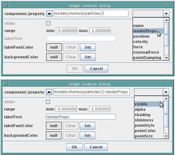
ArtiSynth User Interface Guide 3
4.3.1 Click and box selection . . . . . . . . . . . . . . . . . . . . . . . . . . . . . . . . . . . . . . . . 15
4.3.2 Elliptic selection . . . . . . . . . . . . . . . . . . . . . . . . . . . . . . . . . . . . . . . . . . . 16
4.3.3 Selection filtering . . . . . . . . . . . . . . . . . . . . . . . . . . . . . . . . . . . . . . . . . . . 16
4.4 Selection display . . . . . . . . . . . . . . . . . . . . . . . . . . . . . . . . . . . . . . . . . . . . . . . 16
4.5 Selecting parent and ancestor components . . . . . . . . . . . . . . . . . . . . . . . . . . . . . . . . . . 17
4.6 Highlighting selected components . . . . . . . . . . . . . . . . . . . . . . . . . . . . . . . . . . . . . . 17
5 Model Manipulation 17
5.1 Dragger fixtures . . . . . . . . . . . . . . . . . . . . . . . . . . . . . . . . . . . . . . . . . . . . . . . . 17
5.2 Transformer tools . . . . . . . . . . . . . . . . . . . . . . . . . . . . . . . . . . . . . . . . . . . . . . . 18
5.2.1 Constrained transformation . . . . . . . . . . . . . . . . . . . . . . . . . . . . . . . . . . . . . . 19
5.2.2 Transformer repositioning . . . . . . . . . . . . . . . . . . . . . . . . . . . . . . . . . . . . . . 19
5.2.3 Changing the transformer base frame . . . . . . . . . . . . . . . . . . . . . . . . . . . . . . . . 19
5.3 Pull manipulation . . . . . . . . . . . . . . . . . . . . . . . . . . . . . . . . . . . . . . . . . . . . . . . 19
5.4 Marker tool . . . . . . . . . . . . . . . . . . . . . . . . . . . . . . . . . . . . . . . . . . . . . . . . . . 20
6 Editing Properties 20
6.1 Property panels . . . . . . . . . . . . . . . . . . . . . . . . . . . . . . . . . . . . . . . . . . . . . . . . 21
6.1.1 Inheritable properties . . . . . . . . . . . . . . . . . . . . . . . . . . . . . . . . . . . . . . . . . 21
6.2 Render properties . . . . . . . . . . . . . . . . . . . . . . . . . . . . . . . . . . . . . . . . . . . . . . . 22
6.2.1 Render property settings . . . . . . . . . . . . . . . . . . . . . . . . . . . . . . . . . . . . . . . 22
7 The Timeline 24
7.1 Probes and waypoints . . . . . . . . . . . . . . . . . . . . . . . . . . . . . . . . . . . . . . . . . . . . . 24
7.2 Basic timeline structure . . . . . . . . . . . . . . . . . . . . . . . . . . . . . . . . . . . . . . . . . . . . 24
7.2.1 Play controls . . . . . . . . . . . . . . . . . . . . . . . . . . . . . . . . . . . . . . . . . . . . . 25
7.2.2 Tracks . . . . . . . . . . . . . . . . . . . . . . . . . . . . . . . . . . . . . . . . . . . . . . . . . 25
7.3 Viewing and setting waypoints . . . . . . . . . . . . . . . . . . . . . . . . . . . . . . . . . . . . . . . . 25
7.3.1 Waypoints . . . . . . . . . . . . . . . . . . . . . . . . . . . . . . . . . . . . . . . . . . . . . . 25
7.3.2 Breakpoints . . . . . . . . . . . . . . . . . . . . . . . . . . . . . . . . . . . . . . . . . . . . . . 26
7.3.3 Saving and loading . . . . . . . . . . . . . . . . . . . . . . . . . . . . . . . . . . . . . . . . . . 26
7.4 Tracks and probes . . . . . . . . . . . . . . . . . . . . . . . . . . . . . . . . . . . . . . . . . . . . . . . 26
7.4.1 Creating, moving, and deleting tracks . . . . . . . . . . . . . . . . . . . . . . . . . . . . . . . . 27
7.4.2 Muting tracks . . . . . . . . . . . . . . . . . . . . . . . . . . . . . . . . . . . . . . . . . . . . . 27
7.4.3 Expanding tracks . . . . . . . . . . . . . . . . . . . . . . . . . . . . . . . . . . . . . . . . . . . 27
7.4.4 Grouping tracks . . . . . . . . . . . . . . . . . . . . . . . . . . . . . . . . . . . . . . . . . . . . 27
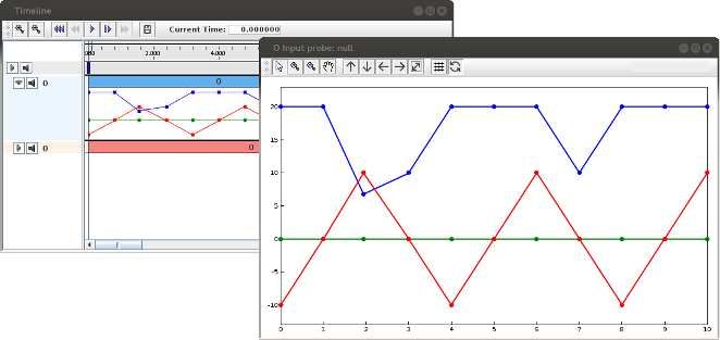
7.5 Numeric probe displays . . . . . . . . . . . . . . . . . . . . . . . . . . . . . . . . . . . . . . . . . . . . 28
7.5.1 Setting the range and display properties . . . . . . . . . . . . . . . . . . . . . . . . . . . . . . . 28
7.5.2 Visibility control . . . . . . . . . . . . . . . . . . . . . . . . . . . . . . . . . . . . . . . . . . . 28
7.5.3 Editing and scaling data . . . . . . . . . . . . . . . . . . . . . . . . . . . . . . . . . . . . . . . 29
7.5.4 Interpolation control . . . . . . . . . . . . . . . . . . . . . . . . . . . . . . . . . . . . . . . . . 29
7.5.5 Large displays . . . . . . . . . . . . . . . . . . . . . . . . . . . . . . . . . . . . . . . . . . . . 30
7.5.6 Cloning displays and exporting plots . . . . . . . . . . . . . . . . . . . . . . . . . . . . . . . . . 31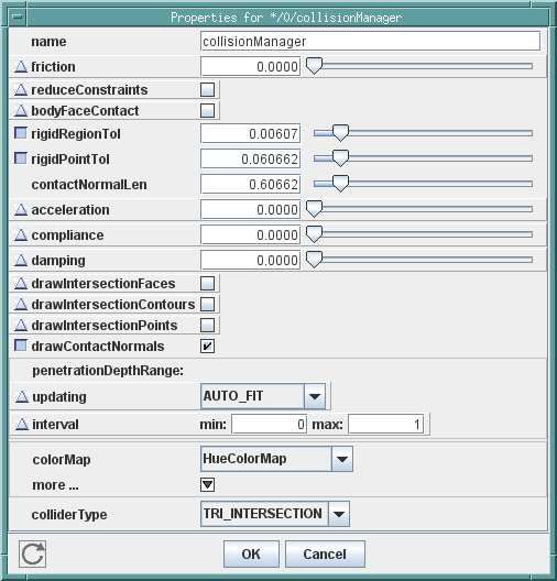
ArtiSynth User Interface Guide                                                                                               4

8   Saving and Loading Probes                                                                                                31
    8.1   Saving and loading probe data . . . . . . . . . . . . . . . . . . . . . . . . . . . . . . . . . . . . . . . .      31
    8.2   Exporting numeric probe data . . . . . . . . . . . . . . . . . . . . . . . . . . . . . . . . . . . . . . . .       32
    8.3   Saving and loading all probes . . . . . . . . . . . . . . . . . . . . . . . . . . . . . . . . . . . . . . . . .    33

9   Adding and Editing Numeric Probes                                                                                        33
    9.1   Adding output probes . . . . . . . . . . . . . . . . . . . . . . . . . . . . . . . . . . . . . . . . . . . . .     33
          9.1.1   Creating a simple probe . . . . . . . . . . . . . . . . . . . . . . . . . . . . . . . . . . . . . . .      34
          9.1.2   General output probes . . . . . . . . . . . . . . . . . . . . . . . . . . . . . . . . . . . . . . . .      34
          9.1.3   Using the probe editor . . . . . . . . . . . . . . . . . . . . . . . . . . . . . . . . . . . . . . . .     35
    9.2   Adding input probes . . . . . . . . . . . . . . . . . . . . . . . . . . . . . . . . . . . . . . . . . . . . .      35
          9.2.1   Creating a simple probe . . . . . . . . . . . . . . . . . . . . . . . . . . . . . . . . . . . . . . .      36
          9.2.2   General input probes . . . . . . . . . . . . . . . . . . . . . . . . . . . . . . . . . . . . . . . . .     36
          9.2.3   Using the probe editor . . . . . . . . . . . . . . . . . . . . . . . . . . . . . . . . . . . . . . . .     36
    9.3   Setting probe properties . . . . . . . . . . . . . . . . . . . . . . . . . . . . . . . . . . . . . . . . . . . .   37

10 Point Tracing                                                                                                             37
    10.1 Rendering only the trace(s) . . . . . . . . . . . . . . . . . . . . . . . . . . . . . . . . . . . . . . . . . .     38

11 Making Movies                                                                                                             38
    11.1 Region to capture options . . . . . . . . . . . . . . . . . . . . . . . . . . . . . . . . . . . . . . . . . . .     38
    11.2 Record options . . . . . . . . . . . . . . . . . . . . . . . . . . . . . . . . . . . . . . . . . . . . . . . .      39
    11.3 Output options . . . . . . . . . . . . . . . . . . . . . . . . . . . . . . . . . . . . . . . . . . . . . . . .      39
    11.4 Output size options . . . . . . . . . . . . . . . . . . . . . . . . . . . . . . . . . . . . . . . . . . . . . .     40

12 Control Panels                                                                                                            41
    12.1 Creating control panels . . . . . . . . . . . . . . . . . . . . . . . . . . . . . . . . . . . . . . . . . . . .     41
          12.1.1 Composite property widgets . . . . . . . . . . . . . . . . . . . . . . . . . . . . . . . . . . . . .        42
          12.1.2 Widgets for sub-properties . . . . . . . . . . . . . . . . . . . . . . . . . . . . . . . . . . . . . .      42
    12.2 Editing control panels . . . . . . . . . . . . . . . . . . . . . . . . . . . . . . . . . . . . . . . . . . . . .    43
    12.3 Live updating . . . . . . . . . . . . . . . . . . . . . . . . . . . . . . . . . . . . . . . . . . . . . . . . .     44

13 Component Editing                                                                                                         44
    13.1 Generic edit operations . . . . . . . . . . . . . . . . . . . . . . . . . . . . . . . . . . . . . . . . . . . .     44
          13.1.1 Deletion . . . . . . . . . . . . . . . . . . . . . . . . . . . . . . . . . . . . . . . . . . . . . . . .    44
          13.1.2 Duplication . . . . . . . . . . . . . . . . . . . . . . . . . . . . . . . . . . . . . . . . . . . . . .     44
          13.1.3 Undo . . . . . . . . . . . . . . . . . . . . . . . . . . . . . . . . . . . . . . . . . . . . . . . . .      44
    13.2 Editing panels . . . . . . . . . . . . . . . . . . . . . . . . . . . . . . . . . . . . . . . . . . . . . . . . .    45
    13.3 Specifying position, orientation, and scaling . . . . . . . . . . . . . . . . . . . . . . . . . . . . . . . . .     45
    13.4 Editing MechModels . . . . . . . . . . . . . . . . . . . . . . . . . . . . . . . . . . . . . . . . . . . . .        45
          13.4.1 Adding finite element models . . . . . . . . . . . . . . . . . . . . . . . . . . . . . . . . . . . .        46
          13.4.2 Adding rigid bodies . . . . . . . . . . . . . . . . . . . . . . . . . . . . . . . . . . . . . . . . .       47
          13.4.3 Adding frame markers . . . . . . . . . . . . . . . . . . . . . . . . . . . . . . . . . . . . . . . .        47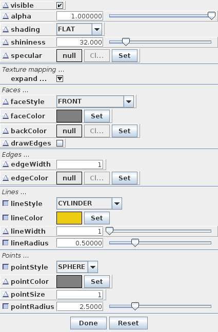
ArtiSynth User Interface Guide                                                                                               5

         13.4.4 Adding particles . . . . . . . . . . . . . . . . . . . . . . . . . . . . . . . . . . . . . . . . . . .       49
         13.4.5 Adding axial springs and muscles . . . . . . . . . . . . . . . . . . . . . . . . . . . . . . . . . .         50
         13.4.6 Adding rigid body connectors . . . . . . . . . . . . . . . . . . . . . . . . . . . . . . . . . . . .         51
         13.4.7 Attaching particles to particles . . . . . . . . . . . . . . . . . . . . . . . . . . . . . . . . . . . .     52
         13.4.8 Attaching particles to rigid bodies . . . . . . . . . . . . . . . . . . . . . . . . . . . . . . . . . .      52
         13.4.9 Collision handling . . . . . . . . . . . . . . . . . . . . . . . . . . . . . . . . . . . . . . . . . .       53
   13.5 Editing rigid bodies . . . . . . . . . . . . . . . . . . . . . . . . . . . . . . . . . . . . . . . . . . . . . .     55
         13.5.1 Geometry and inertia . . . . . . . . . . . . . . . . . . . . . . . . . . . . . . . . . . . . . . . . .       56
   13.6 Editing FEM models . . . . . . . . . . . . . . . . . . . . . . . . . . . . . . . . . . . . . . . . . . . . .         57
         13.6.1 Adding FEM markers . . . . . . . . . . . . . . . . . . . . . . . . . . . . . . . . . . . . . . . .           57
         13.6.2 Adding muscle bundles . . . . . . . . . . . . . . . . . . . . . . . . . . . . . . . . . . . . . . . .        58
   13.7 Editing muscle bundles . . . . . . . . . . . . . . . . . . . . . . . . . . . . . . . . . . . . . . . . . . . .       58
         13.7.1 Adding fibres . . . . . . . . . . . . . . . . . . . . . . . . . . . . . . . . . . . . . . . . . . . . .      59
         13.7.2 Adding element references . . . . . . . . . . . . . . . . . . . . . . . . . . . . . . . . . . . . . .        59
         13.7.3 Automatically setting elements and directions . . . . . . . . . . . . . . . . . . . . . . . . . . . .        60
         13.7.4 Removing fibres and element references . . . . . . . . . . . . . . . . . . . . . . . . . . . . . . .         61
   13.8 Editing muscle exciters . . . . . . . . . . . . . . . . . . . . . . . . . . . . . . . . . . . . . . . . . . . .      61
   13.9 Editing root models . . . . . . . . . . . . . . . . . . . . . . . . . . . . . . . . . . . . . . . . . . . . . .      62

14 Customizing the Models Menu                                                                                               62
   14.1 Plain text format . . . . . . . . . . . . . . . . . . . . . . . . . . . . . . . . . . . . . . . . . . . . . . .      62
   14.2 XML format       . . . . . . . . . . . . . . . . . . . . . . . . . . . . . . . . . . . . . . . . . . . . . . . . .   62
         14.2.1 The root element . . . . . . . . . . . . . . . . . . . . . . . . . . . . . . . . . . . . . . . . . . .       63
         14.2.2 Models . . . . . . . . . . . . . . . . . . . . . . . . . . . . . . . . . . . . . . . . . . . . . . . .       63
         14.2.3 Separators . . . . . . . . . . . . . . . . . . . . . . . . . . . . . . . . . . . . . . . . . . . . . . .     64
         14.2.4 Labels . . . . . . . . . . . . . . . . . . . . . . . . . . . . . . . . . . . . . . . . . . . . . . . . .     64
         14.2.5 Sub-menus . . . . . . . . . . . . . . . . . . . . . . . . . . . . . . . . . . . . . . . . . . . . . .        64
         14.2.6 Packages . . . . . . . . . . . . . . . . . . . . . . . . . . . . . . . . . . . . . . . . . . . . . . .       64
         14.2.7 Plain text files . . . . . . . . . . . . . . . . . . . . . . . . . . . . . . . . . . . . . . . . . . . . .   65
         14.2.8 History . . . . . . . . . . . . . . . . . . . . . . . . . . . . . . . . . . . . . . . . . . . . . . . .      66
         14.2.9 Importing other XML files . . . . . . . . . . . . . . . . . . . . . . . . . . . . . . . . . . . . . .        66
         14.2.10 Hiding elements . . . . . . . . . . . . . . . . . . . . . . . . . . . . . . . . . . . . . . . . . . .       66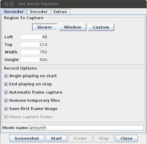
ArtiSynth User Interface Guide                                                                                            6

1 Introduction

This manual describes the ArtiSynth user interface, and how it can be used to edit models and interactively monitor and
control their simulation.

2 Loading, Simulating and Saving Models

The first thing an ArtiSynth user is likely to want is to load a demonstration model, and explore and simulate it.
A number of predefined demonstration models come bundled with the ArtiSynth distribution. These are generally
simple models that illustrate particular simulation capabilities. More complex anatomical models, including those
used in various research projects, are available in the separate project artisynth_models, which must be downloaded
separately (see www.artisynth.org/models for instructions).
An ArtiSynth model is defined by a Java class which is a subclass of the ArtiSynth RootModel component. This class
builds the model, serves as the root container for all its components, and implements the advance() method which
allows the model to be simulated.
There are several ways to load models.

2.1 Loading from the Models menu

Some models can be loaded directly using the Models menu located in the ArtiSynth menu bar. By default, this expands
to a number of submenus:
 Demos         - all models listed in the file .demoModels
 All Demos     - every model found under the package artisynth.demos, arranged hierarchically
In addition, if artisynth_models has also been installed, or if ArtiSynth otherwise detects the presence of Java
packages located under artisynth.models, then the Models menu will also contain:
 Models        - all models listed in the file .mainModels
 All Models    - every model found under the packages artisynth.models, arranged hierarchically
The files .demoModels and .mainModels are searched for in the list of directories specified by the ARTISYNTH_PATH
environment variable (which if not present defaults to the current directory, the user’s home directory, and the ArtiSynth
install directory).
Each submenu expands out to identify a set of models. Selecting one of the models will cause it to be loaded into
ArtiSynth and displayed in the viewer. Hovering over one of the entries will display the full classname of the associated
RootModel.

  It is possible to customize the contents of the Models menu; see Section 14.

2.2 Loading by class path

As mentioned above, models are defined by subclasses of RootModel. A model may therefore be loaded into ArtiSynth
by specifying the classname of its RootModel. To do this, go to the File menu and choose Load from class ..., which will
bring up a dialog that permits you to enter the classname. The dialog supports expansion using the  key.
It is also possible to use the -model  command line argument to have a model loaded directly into
ArtiSynth when it starts up. For example, when running ArtiSynth using the artisynth command, one may specify
  artisynth - model artisynth . models . mystuff . TestModel

Under Eclipse, the -model argument may be specified in the Arguments section of the run configuration.
ArtiSynth User Interface Guide                                                                                                7

2.3 Loading from a file

Finally, it is possible to load a model from a file. Selecting Load model ... from the File menu will bring up a File
browser that lets you select and load a model from an ArtiSynth model file. ArtiSynth model files are text-based
documents that contain a hierarchical description of all the model’s components, and are typically identified by the
extension .art.

  When loading a model from a .art file, it is necessary to have all classes associated with that model in the current
  Java classpath. This can be an issue when loading files generated by other users using application-specific Java
  code. Two possible solutions to this are: (a) bundling the application-specific code into a .jar file and placing it
  in the directory /lib, or (b) making sure that the file was saved using only artisynth_core
  components, as described in Section 2.7.

2.4 Reloading a model

After a model has been loaded by any of the methods described above, it can be reloaded by selected Reload model from
the File menu.

2.5 Simulating a model

Once a model is loaded, simulation of the model can be started, paused, single-stepped, or reset using the play controls
(Figure 1) located at the upper right of the ArtiSynth window frame. Play controls are discussed in more detail in
Section 7.2.1.
Play controls are also available in the ArtiSynth timeline (Section 7). Also, hitting the ‘p’, ‘s’ and ‘r’ keys from within
the viewer (Section 3.9) can be used to play/pause, single step and reset the simulation.

Figure 1: The ArtiSynth play controls. From left to right: step size control, current simulation time, and the reset, skip-
back, play/pause, single-step and skip-forward buttons.

2.6 Other toolbar controls

The ArtiSynth application contains a toolbar that runs along the top of the frame. The right side contains the play
controls shown in Figure 1.
When a grid is enabled in the viewer (Section 3.5), a text box appears in the center of the toolbar displaying the current
grid units (Section 3.5.1).
The left side of the toolbar contains the following buttons:

          NavPanel:              Shows or hides the navigation panel (Section 4.2)

          Reset state:           Resets the simulation state at time 0 to the current state.

          Rerender:              Rerenders all viewers and displays.

          Enable real-time:      Toggle which if pressed (the default), forces the simulation to run no faster than real time.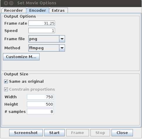
ArtiSynth User Interface Guide                                                                                               8

2.7 Saving a model

An ArtiSynth model can be saved to a file to be reloaded and used later. Selecting Save model as ... from the File
menu will bring up a dialog that lets you select the name and directory for the model file (Figure 2). If a model file has
already been specified, then one can save to it again by selecting the Save model menu item. ArtiSynth model files are
text-based and are typically identified by the extension .art.

                                             Figure 2: The save model dialog.

When using the Save model as ... menu item, the user may choose the following options:

Save waypoint data:
      Causes the state data for any valid waypoints (Section 7.3) to be saved in addition to the waypoint locations. This
      is optional because a large number of waypoints may significantly increase the file size for models with a large
      state sizes.
Core components only:
      Saves only those components which are present in the main artisynth_core package. Any non-core compo-
      nents, and any other components which have a hard dependency on them, will not be written, and the user will
      be advised of this via a message dialog. The root model (Section 4.1) is saved as a pure instance of RootModel,
      instead of the application-specific class that was used to build it. This means that any properties or class overrides
      specific to the application root model class will not be present in the saved model. The advantage to storing a
      model using only core components is that it can be loaded by any other user running that same ArtiSynth version,
      without needing access to any application-specific classes.

2.8 The ArtiSynth working directory

ArtiSynth maintains the notion of a working directory, which is the default directory (or folder, in Windows parlance)
under which the files used to store various types of model information are stored. This includes model files, as described
above, along with other files such as those used to store waypoints, probe configurations, or probe data (Section 8).
Chooser dialogs for these files will generally open in the working directory by default.
The working directory is initialized to the local system directory in which the ArtiSynth application is started. Once
ArtiSynth is running, it can be set by choosing Set working dir ... from the File menu, or by calling

   ArtisynthPath.setWorkingDir (file)

in code. When a model is saved (Section 2.7), the working directory is saved with it and restored when the model file is
subsequently loaded.

3 The Viewer

The viewer provides interactive graphical rendering of the ArtiSynth model and permits selection of its components. A
viewer is integrated into the ArtiSynth main frame; additional viewers can be created if necessary.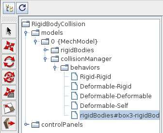
ArtiSynth User Interface Guide                                                                                             9

3.1 Viewer Toolbar

Each viewer is provided with a toolbar (Figure 3) equipped with icons for controlling the viewpoint (Section 3.2) and
clipping planes (Section 3.6). The toolbar for the main viewer appears vertically at the lower left of the main frame,
while toolbars for additional viewers appear horizontally at the top. Each is an instance of Java’s JToolBar, and so can
be moved and docked accordingly.

                                                Figure 3: The viewer toolbar.

3.2 Viewpoint control

The viewpoint can be controlled interactively using mouse drag actions. On systems with a three-button mouse, this is
generally done using the middle mouse button (MMB), in conjunction with the SHIFT and CTRL modifier keys:

MMB
      Rotates the viewpoint about the viewer center point.
MMB + SHIFT
      Translates the viewpoint in a plane perpendicular to the line of sight.
MMB + CTRL or mouse WHEEL
      Zooms in or out by moving the viewpoint along the line of sight. Rotate wheel forward or drag mouse forward
      with CTRL and middle mouse button pressed to zoom in. Rotate or drag backwards to zoom out.

  On systems that have a one or two button mouse, the mouse bindings are adjusted by default so that the ALT
  modifier key emulates the middle mouse button. Mouse bindings are discussed in detail in Section 3.8.

Predetermined viewpoints can also be selected using the align axis button located on the viewer control bar. Clicking
on this button produces an icon menu showing six different axis-aligned views. Each view is indicated by the two axes
perpendicular to the line of sight, with the X, Y, and Z axes illustrated by red, green, and blue lines respectively:

          Front:      Z axis up, X axis to the right.

          Back:       Z axis up, X axis to the left.

          Top:        Y axis up, X axis to the right.

          Bottom:     Y axis down, X axis to the right.

          Left:       Z axis up, y axis to the right.

          Right:      Z axis up, y axis to the left.
The align axis button itself displays the most recently selected axis-aligned view. Hitting the ‘v’ key from within the
viewer (Section 3.9) will realign the viewpoint to this view.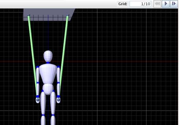
ArtiSynth User Interface Guide                                                                                             10

                                            Figure 4: Viewer showing the grid.

3.3 Adding additional viewers

Additional viewers can be created by selecting View > New viewer from the main menu. Each viewer provides indepen-
dent viewing and selection control for the current model.

  We are considering adding an option whereby the main viewer can be split into four independent viewing panels,
  providing orthogonal projections of the front, side, and top, along with a general perspective projection. This
  arrangement is common in CAD and geometric modeling applications.

3.4 Orthographic vs. perspective projection

The user can toggle between orthographic and perspective projection by selecting View > Orthographic view or View >
Perspective view from the main menu. Toggling can also be achieved using the ‘o’ key shortcut (Section 3.9) within the
viewer.

3.5 Viewer grid

Hitting the ‘g’ key within the viewer enables or disables a grid (Figure 4). Grid cells are square and appear in two
resolutions, with major cells subdivided into a number of minor cells. Major cells are typically rendered more brightly
than minor cells. By default, the grid computes the cell sizes automatically based on the current viewer zoom-level.
However, it is possible to set an explicit grid resolution (see 3.5.1).
The grid is located in the plane perpendicular to the line of sight of the most recently selected axis-aligned view. To
change the grid plane, select a new axis aligned viewpoint (Section 3.2).

3.5.1 Grid units

When the grid is enabled, a box labeled Grid: appears in the toolbar on top of the main ArtiSynth frame which gives
the current resolution of the grid, displayed as S/N, where S is the size of each major grid cell and N is the number of
subdivisions per cell. If there are no subdivisions, then the /N is omitted. For example, in Figure 4, this appears as
Grid: 1/10, which means that the major grid cells have a size of 1.0 and are each divided into 10 subdivisions. The
numeric value of the ratio S/N gives the minor cell size.
By default, the grid automatically resizes itself to the current viewer zoom level, choosing well-rounded numbers for the
grid cell size. Auto-sizing can be enabled or disabled by right-clicking on the Grid: label and choosing Turn auto-sizing
ArtiSynth User Interface Guide 11
on or Turn auto-sizing off, as appropriate. The user can also specify an explicit value for the grid resolution by entering
the desired S/N value (or just an S value) into the Grid: box. Specifying an explicit value will disable auto-sizing,
unless S is specified as 0 or the special value * is entered, both of which will re-enable auto-sizing.
3.5.2 Axis labeling
Hitting the ‘l’ key within the viewer enables or disables labeling of the major divisions along the horizontal and vertical
axis (Figure 5). The division lines along which these labels appear are automatically adjusted so as to ensure proper
label visibility, and do not necessarily correspond to the x, y, or z axes.
Figure 5: Viewer grid with axis labels visible.
It is possible to control various properties associated with axis labeling, such as which axes are labeled, and the label
size and color. See the next section on Grid properties.
3.5.3 Grid properties
The grid has a number of properties that can be set by right-clicking in the viewer and choosing Set viewer grid
properties (or by right-clicking on the Grid: label and choosing Set properties). This will bring up a property dialog,
such as that shown in Figure 6.
Properties that can be set include:
resolution
Grid resolution, as described above.
autoSized
If true, causes the grid resolution to be recomputed as the user adjusts the view position, orientation, and zoom.
minCellPixels
Minimum number of pixels that should appear in a minor cell division when autosizing.
majorColor
Color to use for the major axis lines.
minorColor
Color to use for the minor axis lines.
xAxisColor
Color to use for the grid line that corresponds to the world y axis, or the horizontal axis if lockAxesToWorld is
false.ArtiSynth User Interface Guide 12
Figure 6: Dialog to control the grid properties.
yAxisColor
Color to use for the grid line that corresponds to the world y axis, or the vertical axis if lockAxesToWorld is false.
zAxisColor
Color to use for the grid line that corresponds to the world z axis.
lineWidth
Width of the grid lines, in pixels.
position
Translation position of the grid, in world coordinates.
orientation
Orientation of the grid, in world coordinates.
lockAxesToWorld
If true, forces the grid to stay aligned with the orientation and position of the world axes. In particular, the
horizontal and vertical axes will always be parallel to one of the x, y, or z world axes, the grid center will be a
multiple of major cell sizes from the origin, and axis labels will be set relative to the world origin.
useWorldOrigin
If true, causes the principal horizontal and vertical axes to be aligned with the world origin. Otherwise, the axes
will be aligned with the grid center. This property can only be true if lockAxesToWorld is also true.
xAxisLabeling
Enables labeling of the x axis.
yAxisLabeling
Enables labeling of the y axis.
labelSize
’em’ size of the label text, in pixels.
labelColor
If set, specifies the color used to draw the label text. Otherwise, the major axis color is used.ArtiSynth User Interface Guide 13
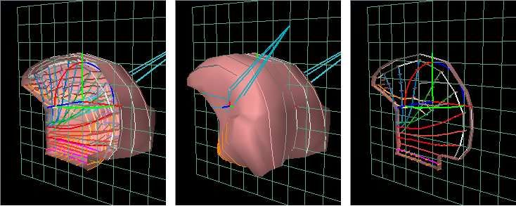
Figure 7: Clipping plane showing interior of tongue model (left), disabled (center), and in slice mode (right).
3.6 Clipping planes
The user can add clipping planes to the viewer. These are useful for restricting what is rendered and allowing a better
view of interior structures, as shown in (Figure 7).
3.6.1 Adding and removing
To add a clipping plane, left click on the add clip plane button located on the viewer toolbar. This will create a
clipping plane located in the plane perpendicular to the current line of sight.
It will also add to the viewer toolbar a clip plane icon for controlling the clipping plane. Right-clicking on this icon
will bring up an option menu.
To delete a clipping plane, right-click on its icon and select Delete.
3.6.2 Moving
A clip plane is associated with a coordinate system and can be moved and/or rotated by dragging on the trans-rotate
transformer located at its coordinate system origin. The clip region is the half space lying in the direction of the +z axis.
The transformer itself can be made invisible/visible by right-clicking on the clip plane icon and selecting Hide trans-
former or Show transformer.
3.6.3 Offsets
The clipping region is the half space lying in the direction of the +z axis of the plane’s local coordinate system. By
default, clipping is actually offset by a small distance along the +z axis, so that small objects (such as points) lying in the
x-y plane remain visible. The amount of this offset is controlled by the plane’s offset property, which is set to a nominal
default value. To control this property directly, right-click on the clip plane icon and select Set properties. This will
bring up a panel which allows the offset to be adjusted.
3.6.4 Enabling/disabling
Left clicking on the clip plane icon will enable/disable clipping. Disabling clipping allows the plane to be used as a
regular movable grid. When clipping is disabled, the icon will change to the form .
3.6.5 Slicing mode
Clipping planes can be placed in a slicing mode, whereby half-spaces in both the positive and negative z directions are
clipped. The result is a small slice about the local x-y plane (Figure 7, right). The width of this slice is controlled by the
plane’s offset property, as described above.
To enable or disable slicing, right-click on the clip plane icon and select Enable slicing or Disable slicing.ArtiSynth User Interface Guide 14
3.6.6 Other features
Properties
Various properties associated with the plane, such as its color, line width, cell resolution, etc., can be set explicitly
by the user. To do this, right-click on the icon, select Set properties, and edit the resulting property panel. Most
properties are the same as those described for the main viewer grid in 3.5.3.
Grid visibility
To make the grid invisible/visible, right-click on the icon and select Hide grid or Show grid.
Alignment with world axes
The clip plane can be aligned so that it’s normal lies along the positive or negative direction of either the x, y, or z
world axes. Right-click on the icon and select the appropriate option. Clipping is performed so that the half-space
lying in the direction of the normal is clipped.
Alignment with current line of sight
To align the clipping plane so that it is perpendicular to the current line of sight, right-click on the icon and select
Reset.
3.7 Indicating 3D positions with the mouse
It is possible to use a viewer in combination with a mouse to specify the position of a 3D point in space. This is
commonly employed in the editing operations described in Section 13.
To specify a point, the user left-clicks the mouse in the viewer, at the screen position located over the point’s desired
position. The 3D position is then determined by intersecting the ray indicated by the mouse clock with some appropriate
surface or plane. Typically, a plane perpendicular to the viewing direction and passing through the model’s center is
used. Alternatively, some interactions provide a constrain to plane option, which causes the ray to be intersected with
a viewer clipping plane (Section 3.6), providing more precise control over the point’s position. This requires that the
viewer presently contain at least one clipping plane. If more than one clipping plane is present, the first one is used.
In other applications, the desired point may be known to lie on a 3D surface, in which case the position is determined by
intersecting the ray with a 3D surface mesh.
3.8 Alternate mouse bindings
The ArtiSynth GUI was originally designed for a three-button mouse, in which the left button is used for selection,
the middle button controls the viewpoint, and the right button is used to activate the context menu. These are used in
conjunction with the modifier keys SHIFT and CTRL to effect different actions.
For systems that do not have a three-button mouse, ArtiSynth by default detects the number of mouse buttons and
adjusts the mouse bindings so that the ALT key emulates the middle button and the META key emulates the right button.
The META key is usually associated with either the COMMAND key (Mac) or the WINDOWS key.
Mouse bindings can also be explicitly set by the user, by opening the mouse preferences dialog Settings > Mouse
Preferences and then choosing the desired binding. This dialog also displays the button and modifier combinations asso-
ciated with different actions. Alternate bindings may also be requested from the command line using the -mousePrefs
option. Currently, there are three default and two legacy bindings:
ThreeButton
Default bindings for a three-button mouse.
TwoButton
Default bindings for a two-button mouse. The middle mouse button is emulated with the ALT key.ArtiSynth User Interface Guide 15
OneButton
Default bindings for a one-button mouse. The middle and right mouse buttons is emulated with the ALT and META
keys.
Laptop
Legacy bindings for a two-button mouse.
Mac
Legacy bindings for a Mac type one-button mouse.
Tables showing the button and modifier combinations that effect different actions with each of these binding are given
below, with LMB, MMB, and RMB denoting the left, right and middle mouse buttons. Actions marked with an asterisk (*)
are drag actions which can have their modifier keys invoked or removed during a drag operation.
Action ThreeButton TwoButton OneButton
Viewpoint control (Section 3.2)
Rotate view MMB MMB+ALT MMB+ALT
Translate view MMB+SHIFT MMB+ALT+SHIFT MMB+ALT+SHIFT
Zoom view MMB+CTRL MMB+ALT+CTRL MMB+ALT+CTRL
Component selection (Section 4.3)
Single selection LMB LMB LMB
Multiple selection LMB+CTRL LMB+CTRL LMB+CTRL
Elliptic selection LMB LMB LMB
Elliptic deselection∗ LMB+SHIFT LMB+SHIFT LMB+SHIFT
Resize paint ellipse LMB+SHIFT+CTRL LMB+SHIFT+CTRL LMB+SHIFT+CTRL
Context menu RMB RMB LMB+META
Transformer control (Section 5.2)
Move LMB LMB LMB
Constrained move∗ LMB+SHIFT LMB+SHIFT LMB+SHIFT
Reposition∗ LMB+CTRL LMB+CTRL LMB+CTRL
while the legacy bindings are:
Action Laptop Mac
Viewpoint control (Section 3.2)
Rotate view LMB LMB+ALT
Translate view LMB+SHIFT LMB+ALT+SHIFT
Zoom view LMB+ALT LMB+ALT+META
Component selection (Section 4.3)
Single selection LMB+CTRL LMB
Multiple selection LMB+SHIFT+CTRL LMB+META
Elliptic selection LMB+CTRL LMB
Elliptic deselection∗ LMB+SHIFT+CTRL LMB+SHIFT
Resize paint ellipse LMB+SHIFT+CTRL LMB+SHIFT+CTRL
Context menu RMB LMB+CTRL
Transformer control (Section 5.2)
Move LMB LMB
Constrained move∗ LMB+SHIFT LMB+SHIFT
Reposition∗ LMB+ALT LMB+ALT
3.9 Keyboard shortcuts
When the viewer has the keyboard focus, the following key shortcuts are available:ArtiSynth User Interface Guide 16
Key Operation
q quit ArtiSynth
t toggle time line visibility
z undo last command
Play controls (Section 2.5):
p or SPC play/pause
s single step
r reset
Viewer controls:
v reset view (Section 3.2)
o toggle orthographic/perspective view (Section 3.4)
a toggle visibility of axes showing world coordinates
g toggle viewer grid (Section 3.5)
l toggle viewer grid labels
Selection and transformer (Sections 4.3 and 5.2):
ESC select parent of last selection
c clear selection
d reset elliptic cursor size to default
w set current transformer frame to world coordinates
b set current transformer frame to body/local coordinates
4 Component Navigation and Selection
An ArtiSynth model is composed of a hierarchical arrangement of model components (each of which implements the
interface ModelComponent), some of which may themselves be models. The graphical interface allows users to navigate
this hierarchy and select individual components. Selected components can then be edited, or have specific properties
modified or attached to probes or control panels.
4.1 The component hierarchy
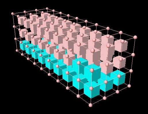
An example component hierarchy is shown in Figure 8. At the top is a root model (class RootModel), in this case named
Rigid Body Spring. The root model in turn contains a list of models, one of which is a mechanical model named
msmod, which here contains particles and rigid bodies.
It is important to node that in the component hierarchy, any collection of components is itself a component (usually
an instance of ComponentList). This provides automatic “grouping” of components of like type, but does introduce
additional levels into the hierarchy. Hence the particle red is a child not of msmod, but rather the component list
particles.
4.1.1 Component names and numbers
Model components may be assigned a string name; at the time of this writing names may not begin with a digit, have
zero length, contain the characters ‘.’ or ‘/’, or equal the reserved word this. Components which do not have an
assigned name are called nameless.
All components have a number, even if they do not have a name. The number is assigned automatically when the
component is added to the parent, and is guaranteed to be persistent until the component is removed from the parent.
4.1.2 Component path names
The names and/or numbers of a component’s ancestors can be used to form a component path name. This path has
a construction completely analogous to Unix file path names, with the ‘/’ character acting as a separator. Absolute
paths start with ‘/’ and begin with the root model. Relative paths omit the leading ‘/’ and can begin lower down in the
hierarchy. The absolute path name of the red particle in Figure 8 would be
/Rigid Body Spring/models/msmod/particles/redArtiSynth User Interface Guide 17
Figure 8: A sample component hierarchy.
Figure 9: An typical navigation panel display.
For nameless components in the path, their numbers can be used instead:
/Rigid Body Spring/models/msmod/rigidBodies/1
Numbers can be used even for components that have names. Hence a path name consisting only of numbers, as in
/0/0/0/3/1
is legal, although it most likely to appear only in machine-generated output.
4.2 Navigation panel selection
A navigation panel in the main ArtiSynth frame allows direct navigation of the component hierarchy. The panel can be
open or closed by clicking on the main toolbar icon .
Figure 9 shows an navigation panel containing a superset of the hierarchy diagrammed in Figure 8.
Left clicking on any component in the navigation panel selects that component. Clicking while pressing the CTRL key
(or the CMD key on some platforms, such as Mac) allows selection of multiple components. Clicking while pressing the
SHIFT key allows selection of a range of components.ArtiSynth User Interface Guide 18
Figure 10: Expansion of nameless components in the navigation panel.
4.2.1 Large numbers of nameless components
In some cases, such as finite element models, the number of child components can be very large (on the order of
thousands). In order to keep the navigation panel size manageable, the number of nameless children displayed is limited
to a set number (currently 100). If the number of nameless children exceeds this number, the display will be augmented
with an expand icon »>. Clicking on this will expand the display to include all nameless components, and the expand
icon will be replaced by a contract icon «ArtiSynth User Interface Guide 19
Figure 11: The selection filter widget.
4.3.2 Elliptic selection
Elliptic selection is enabled by the elliptic icon near the top of the selection toolbar:
This causes an additional elliptic cursor (which defaults to a circle) to be drawn around the mouse cursor. Selection is
effected by dragging, and causes all visible objects within the ellipse to be selected. The selection process is cumulative,
with subsequent drags selecting additional components. As with all selection operations, a filter can be set to restrict the
components that are selected (Section 4.3.3). Generally, the drag select operation requires no modifier keys, although it
may with some legacy mouse bindings (Section 3.8).
It is also possible to deselect components in the same way, by using the SHIFT modifier key to cause drag operations to
cumulatively deselect components.
Elliptic selection selects only those components which are actually visible to the viewer; components which are
hidden cannot be selected this way.
The elliptic cursor used for selection can be resized, either interactively, or by setting the ellipticCursorSize
property of the viewer. To interactively change the cursor, initiate a drag operation with the CTRL and SHIFT modifiers.
To set the ellipticCursorSize, invoke the context menu (usually right-click) in the viewer when nothing is selected,
and choose Set viewer properties. Finally, the ‘d’ key shortcut within the viewer will cause the cursor to be reset to its
default size.
4.3.3 Selection filtering
It is possible to limit viewer selection to components of a specific type. This can be done using the selection filter widget
at the bottom left of the main ArtiSynth frame Figure 11.
To enable filtering, type into the widget text box the class name of the component type you wish to restrict filtering to.
It is generally only necessary to enter the leaf name of the class (e.g., Particle or AxialSpring), and the system will
then find the full class name by searching the ArtiSynth class path.
Once filtering is enabled, only components which are instances (including subclasses) of the specified type will be
selectable.
Previously selected filters can be recalled using a history list accessible using the leftmost arrow button on the selection
widget.
To remove selection filtering, enter the special filter *, either by typing this in the text box, or using the history list.
4.4 Selection display
The selection display Figure 12 at the bottom of the main ArtiSynth frame shows the full path name of the last compo-
nent added to the selection list. This is useful for identifying components in detail.
If no components are selected, then the selection display is blank.
The selection display is useful for disambiguating situations where it is not clear what component we have actually
selected in the viewer. For example, FEM models keep their surface mesh contained within a descendant component.
Selecting the surface mesh will cause this container component to be selected and highlighted, making it appear as
though the FEM model itself is selected rather than the container. Checking the selection display makes it clear what
component has actually been selected. If desired, one can easily navigate to one of the ancestor components using parent
selection, as described in the next section.ArtiSynth User Interface Guide 20
Figure 12: The selection display widget.
4.5 Selecting parent and ancestor components
Sometimes, when you select a component, you actually want to select one of it’s ancestor components.
There are several ways to do this:
1. Hit the escape (ESC) key within the viewer window. This will select the parent of the currently selected compo-
nent. Hitting escape repeatedly is a fast way to proceed up the component hierarchy.
2. Click on the “up” arrow located at the left of the selection display (Figure 12). This will also select the parent of
the currently selected component.
Parent selection is particularly useful in the commonly occurring situation where a composite component is not rendered
and therefore not selectable in the viewer. For instance, suppose we wish to select a FEM model. One can select any
renderable descendant of the model, such as a node, element, or its surface mesh (if displayed), and then use repeated
parent selection until the model itself is selected.
4.6 Highlighting selected components
Selected components are rendered in the viewer using a special selection color (yellow at the time of this writing). It is
important to note that descendants of a selected component are not presently rendered in any special way. For instance,
if an FEM is selected, it’s nodes and elements will be rendered normally.
While this has the potential to be confusing, we have not yet found this to be problematic, as the navigation panel and
selection display provide alternative indicators as to what is currently selected.
5 Model Manipulation
Various tools located within the selection toolbar at the left of the main ArtiSynth frame allow models to be manipulated
in various ways. These include modifying component locations, orientations, and geometry using the transformer tools
(Section 5.2), exerting point forces on selected components using the pull controller (Section 5.3), and adding marker
points to certain components types (Section 5.4).
The behavior of these tools is somewhat context dependent. For example, the transformer tools will only transform
those transformable components which implement the TransformableGeometry interface. The behavior may also vary
depending on whether or not simulation is in progress.
5.1 Dragger fixtures
The transformation tools employ the dragger fixtures shown in Figure 13, which allow 3D geometrical transformations
to be performed within the viewer.
Translator
Effects a translation. The x, y, and z axes are indicated by red, green, and blue lines. Dragging any line causes a
one-dimensional motion along the associated axis. Dragging one of the boxes causes a two-dimensional motion in
the associated plane.
Rotator
Effects a rotation. Rotation about the x, y, and z axes is indicated by red, green, and blue circles. Selecting and
dragging along one of these circles produces a rotation about the corresponding axis.ArtiSynth User Interface Guide 21
Figure 13: Dragger fixtures: translator, rotator, and transrotator.
TransRotator
Combines the translator and rotator into a single tool. One difference is that the axes of the transRotator move
with any rotation, and so operations are done with respect to the transRotator coordinate frame at the beginning of
the drag.
Under the default mouse bindings, the basic drag operations involving these fixtures are invoked using the left
mouse button with no modifier keys. Additional modifier keys allow constrained transformation or repositioning of
the fixture, as described below.
5.2 Transformer tools
A number of transformer tools use the dragger fixtures described above to translate, rotate, and scale components.
Once a tool is activated, then selecting one or more transformable components will cause the corresponding dragger
fixture to appear in the viewer at the components’ location. If a single component is selected and that component is
associated with a coordinate frame (by implementing the HasCoordinateFrame interface), then the dragger’s initial
position and orientation are aligned with this coordinate frame. Otherwise, the dragger is initially placed at the center of
the components’ bounding box and its orientation is aligned to world coordinates.
To request that a dragger’s initial orientation is always aligned with world coordinates, choose Init draggers in world
coordinates in the ArtiSynth Settings menu. To restore the default behavior, choose Init draggers in local coordinates.
Translation:
Translates selected components using the translator dragger.
Rotation:
Rotates selected components using the rotator dragger.
TransRotation:
Translates and rotates selected components using the transRotate dragger. The transformation reference frame moves
with the tool.
Constrained translation:
Translates selected components using the translate dragger while ensuring that they are constrained to remain on a
surface mesh. Only components with an associated surface mesh (such as FrameMarkers attached to a RigidBody) can
be transformed this way.
Scaling:
Scales selected components using the transrotator fixture. Instead of translating, translational drag operations scale the
component along the x, y, or z axes, or in the x-y, y-z, or z-x planes. Rotational operations, if used in conjunction with
an appropriate modifier key, can be used to change the orientation of the scaling axes, as described in 5.2.2.ArtiSynth User Interface Guide 22
5.2.1 Constrained transformation
Under the default mouse bindings, pressing the SHIFT modifier key causes drag operations to be constrained to discrete
step sizes. Rotation operations are constrained to intervals of five degrees, while translation operations are constrained
to either the grid spacing (if a grid is selected, see 3.5), or to a suitable well-rounded number depending on the viewer’s
zoom level.
5.2.2 Transformer repositioning
Under the default mouse bindings, pressing the CTRL modifier key causes the dragger fixture to move independently
of the selected objects. This allows its position and orientation relative to the selected objects to be changed. This is
particularly useful for changing the orientation of the scaling directions in the scaling tool.
5.2.3 Changing the transformer base frame
By default, a transformer is assigned a local coordinate frame for the object(s) that it is positioning, based on either the
object’s own body frame (if it has one), or the objects’ bounding box. This frame will then move with the transformer,
and may also move relative to the object(s) if the transformer is repositioned (Section 5.2.2).
Sometimes, it may be desirable to explicitly reset the transformer’s frame. This may be done using the following
shortcut keys in the viewer:
w
Set the transformer frame to the world coordinate system, allowing subsequent transformations to be performed in
world coordinates;
b
Reset the transformer frame to the original local frame for the object(s), based on either the object’s body frame or
the objects’ bounding box.
5.3 Pull manipulation
Pull tool:
Pulls on certain components using a spring-like force when simulation is running.
Figure 14: Applying pull manipulation (blue arrow) to a rigid body attached to a multi-point spring.ArtiSynth User Interface Guide 23
Selecting the pull tool allows a user to interactively apply a spring-like force to certain component types by clicking on it
and then dragging (Figure 14). Double clicking on the component adds a pull point that persists between mouse clicks;
to remove the pull point, double click on the viewer background.
The pull tool works on points, rigid bodies, FEM models, or any other component that implements the PointAttachable
interface and has a surface mesh. Pull manipulation is only effective when simulation is running. It works by adding a
special PullController to the current root model’s set of controllers. When attached to the root model, the controller
attempts to estimate an appropriate spring stiffness based on the overall mass and dimensions of the first underlying
MechModel.
If necessary, the pull tool’s stiffness setting can also be adjusted manually by selecting PullController > properties in the
Settings menu. Render properties for the pull controller can be set from this menu also.
5.4 Marker tool
Marker tool:
Adds point markers to certain components.
Selecting the marker tool allows a user to interactively add point markers to various components in the model.
Markers can be added by double-clicking on rigid bodies, FEM models, and other components that implement the
IsMarkable interface.
Markers are typically added to a component’s surface mesh, and in such cases it is necessary that this surface mesh
be visible. For FEM models in particular, the surfaceRendering property should be set to something other than
None. To ensure this is the case, select the FEM model, right-click and choose Edit properties ..., and examine
the setting for surfaceRendering. An FEM model can sometimes appear to have a visible surface mesh, even if it
doesn’t, if its elementWidgetSize property is close to 1.
The markers themselves are added to the current root model at a location that depends on the component being marked:
• Rigid bodies: marker is added to the frameMarker list for the body’s parent MechModel;
• FEM models: marker is added to the FEM model’s marker list;
• IsMarkable components: marker is added to the root model’s marker list (which is created on demand if needed).
In order for added markers to be visible, the component list into which they are placed needs to be visible, with its
point rendering properties set to appropriate values. That usually means that pointStyle is set to SPHERE or CUBE, with
pointRadius set to a value commensurate with the model’s dimensions, or pointStyle is set to POINT, with pointSize set
to a sufficiently large value in pixels. If not set within the list itself, the point rendering properties will be inherited from
ancestor components. For example, if a MechModel’s point render properties are set for good visibility, then all points
within subcomponents will be visible unless these setting have been overridden at a lower point in the hierarchy.
If markers are not appearing when using the marker tool, use the navigation panel to open the component list to
which the markers are added (as described above). Verify that markers are actually being appended to the end of
the list. If they are not, ensure that the component’s surface mesh is visible. If they are, select the list itself, right-
click, and choose Edit render props .... Check that visible is true, and that pointStyle and pointRadius (or pointSize)
are set appropriately.
Once created, markers can be removed by selecting them and choosing Delete from the context menu.
6 Editing Properties
Most ArtiSynth model components have properties which can be changed onscreen through the graphical interface.
Properties include a diverse set of attributes ranging from stiffness and damping for AxialSprings, position and velocity
for particles and rigid bodies, or whether or not a component is dynamic.
The underlying software architecture of the property interface is described in the Properties chapter of the
Maspack Reference Manual.ArtiSynth User Interface Guide 24
6.1 Property panels
To edit properties for a set of components, select the components in question, then right-click in either the viewer or the
navigation panel, and select Edit properties. This will create a property panel for all properties which are common to the
selected components. All typical property panel is shown in Figure 15.
Property panels are initialized with the current values of the selected components, providing a view of the current prop-
erty state. A blank property value will be displayed when more than one component is selected and the corresponding
property value differs across components.
Some properties are read only. In this case, the corresponding widget in the property panel will display the value but
will be disabled.
Figure 15: A typical property panel.
Property panels are non-modal and persistent. They can be deleted by closing them or clicking the OK button. Clicking
the Cancel button will cause the properties to be reset to their values at the time to panel was created.
Normally, a property panel will refresh its widget values whenever the model view is rerendered. In particular, this will
happen repeatedly while simulation is running. To disable the automatic refresh, click the live updating button at
the lower left of the panel.
6.1.1 Inheritable properties
Some properties are inheritable. The value of an inheritable property can be explicitly set or it can be inherited. If
inherited, then it inherits its value from ancestor components further up the hierarchy. More specifically, if a property’s
value is inherited, then the value is obtained from the nearest ancestor in which the same property exists and is explicitly
set. If no such ancestor exists, then the property is set to a default value.
The inherited/explicit status of an inheritable property is controlled by an additional button placed at the left of the
property widget (Figure 16). Clicking this button toggles the inherited/explicit status. If set to inherited, then the
property’s value is determined from the hierarchy and the updated value is placed in the widget. Setting the value in
the widget itself will cause the inheritable status to be set to explicit, and the value of inherited instances of the same
property in descendant nodes will be updated accordingly.
Figure 16: Property panel showing YoungsModulus as inherited (left) and explicitly set (right).ArtiSynth User Interface Guide 25
6.2 Render properties
Render properties are associated with any component that is renderable. They are defined in the class RenderProps.
Because of their complexity, they are adjusted through a separate panel from the standard property panel.
To adjust the property panel for a set of components, select the components in question, using either the viewer window
or navigation panel, and then right click in either the viewer or the navigation panel. Several options may appear in the
context menu:
Edit render props
This will create a special property panel allowing the render properties for the selected components to be set (see
Section 6.2.1 and Figure 17).
Clear render props
This will actually remove the render properties from the selected components (i.e., their render properties
will be set to null). Nominally, this means that the components will not be rendered, unless their parents
take responsibility for rendering children without render properties. The latter behavior is common for lists of
particles, springs, finite elements, etc., in order to avoid the need for defining render properties in a large number
of objects.
Set visible
This option will appear if any of the selected objects are invisible. Selecting it will set the render properties so that
all components are visible.
Set invisible
This option will appear if any of the selected objects are visible. Selecting it will set the render properties so that
all components are invisible.
6.2.1 Render property settings
There are a large number of render property settings. Loosely speaking, they are divided into generic settings, along
with those related to faces, lines, and points. How these are used depends on what is being rendered. Mesh rendering
typically uses the face settings, along with the line settings to render edges if the drawEdges property is set true. Line
settings are also used for rendering axial springs and the edges of FEM elements. Point settings are used for rendering
any subclass of Point, including Particle and FemNode.
Not all render properties may appear in a render panel; usually, only those properties relevant to the selected components
will be presented.
Generic properties:
visible: Whether or not the component is visible.
alpha: The transparency for polygonal faces (range 0 to 1. Default is 1, for opaque).
shading: How polygons are shaded (FLAT, SMOOTH, METAL and NONE). For viewer implementations there may be
no difference between SMOOTH and METAL.
shininess: Shininess parameter for polygons (range 0 to 128). Default is 32.
specular: If not null, specifies the specular reflectance color.
Face related properties:
faceStyle: Which polygonal faces are drawn (FRONT, BACK, FRONT_AND_BACK, NONE).
faceColor: Color used for drawing faces.
backColor: Color used for drawing backs of faces. If null, faceColor is used.
drawEdges: If true, face edgesof the polygons are drawn explicitly.
Texture mapping properties:
colorMap: If not null, specifies the image source file and properties for color mapping.You can also read