Emerson Smart Wireless Gateway 1420
←
→
Page content transcription
If your browser does not render page correctly, please read the page content below
Reference Manual
                                   00809-0200-4420, Rev HC
                                                 July 2015

Emerson™ Smart Wireless Gateway 1420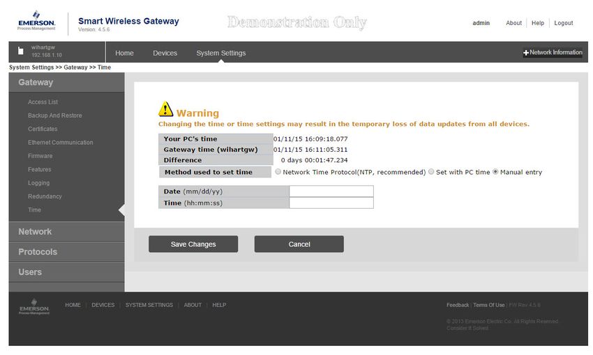
Reference Manual                                                                                                                                           Contents
00809-0200-4420, Rev HC                                                                                                                                        July 2015

Contents
                  1Section 1: Introduction
                          1.1 Product overview . . . . . . . . . . . . . . . . . . . . . . . . . . . . . . . . . . . . . . . . . . . . . . . . . . . . . . . 1
                          1.2 Using this manual. . . . . . . . . . . . . . . . . . . . . . . . . . . . . . . . . . . . . . . . . . . . . . . . . . . . . . . 2

                  2Section 2: Configuration
                          2.1 Overview . . . . . . . . . . . . . . . . . . . . . . . . . . . . . . . . . . . . . . . . . . . . . . . . . . . . . . . . . . . . . . 3
                          2.2 System requirements . . . . . . . . . . . . . . . . . . . . . . . . . . . . . . . . . . . . . . . . . . . . . . . . . . . 3
                          2.3 Initial setup . . . . . . . . . . . . . . . . . . . . . . . . . . . . . . . . . . . . . . . . . . . . . . . . . . . . . . . . . . . . 4
                                2.3.1 Prepare PC/laptop. . . . . . . . . . . . . . . . . . . . . . . . . . . . . . . . . . . . . . . . . . . . . . . . . 4
                                2.3.2 Connections and power. . . . . . . . . . . . . . . . . . . . . . . . . . . . . . . . . . . . . . . . . . . . 5
                                2.3.3 Configure the Gateway . . . . . . . . . . . . . . . . . . . . . . . . . . . . . . . . . . . . . . . . . . . . 8
                                2.3.4 System backup . . . . . . . . . . . . . . . . . . . . . . . . . . . . . . . . . . . . . . . . . . . . . . . . . .12

                  3Section 3: Installation
                          3.1 Overview . . . . . . . . . . . . . . . . . . . . . . . . . . . . . . . . . . . . . . . . . . . . . . . . . . . . . . . . . . . . .13
                                3.1.1 General considerations . . . . . . . . . . . . . . . . . . . . . . . . . . . . . . . . . . . . . . . . . . .13
                                3.1.2 Physical description . . . . . . . . . . . . . . . . . . . . . . . . . . . . . . . . . . . . . . . . . . . . . .13
                          3.2 Mounting . . . . . . . . . . . . . . . . . . . . . . . . . . . . . . . . . . . . . . . . . . . . . . . . . . . . . . . . . . . . .14
                                3.2.1 Pipe mount. . . . . . . . . . . . . . . . . . . . . . . . . . . . . . . . . . . . . . . . . . . . . . . . . . . . . .15
                                3.2.2 Bracket mount (alternate). . . . . . . . . . . . . . . . . . . . . . . . . . . . . . . . . . . . . . . . .15
                          3.3 Remote antenna (optional) . . . . . . . . . . . . . . . . . . . . . . . . . . . . . . . . . . . . . . . . . . . . .16
                          3.4 Connecting . . . . . . . . . . . . . . . . . . . . . . . . . . . . . . . . . . . . . . . . . . . . . . . . . . . . . . . . . . .19
                                3.4.1 Grounding . . . . . . . . . . . . . . . . . . . . . . . . . . . . . . . . . . . . . . . . . . . . . . . . . . . . . .19
                                3.4.2 Ethernet . . . . . . . . . . . . . . . . . . . . . . . . . . . . . . . . . . . . . . . . . . . . . . . . . . . . . . . .19
                                3.4.3 RS-485. . . . . . . . . . . . . . . . . . . . . . . . . . . . . . . . . . . . . . . . . . . . . . . . . . . . . . . . . .20
                                3.4.4 Terminating resistors . . . . . . . . . . . . . . . . . . . . . . . . . . . . . . . . . . . . . . . . . . . . .21
                                3.4.5 Power . . . . . . . . . . . . . . . . . . . . . . . . . . . . . . . . . . . . . . . . . . . . . . . . . . . . . . . . . .22
                                3.4.6 Power over Ethernet (PoE) . . . . . . . . . . . . . . . . . . . . . . . . . . . . . . . . . . . . . . . .22

Contents                                                                                                                                                                iii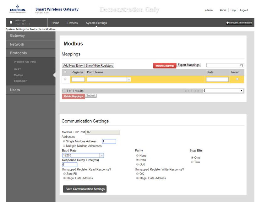
Contents Reference Manual
July 2015 00809-0200-4420, Rev HC
4Section 4: Commissioning
4.1 Overview . . . . . . . . . . . . . . . . . . . . . . . . . . . . . . . . . . . . . . . . . . . . . . . . . . . . . . . . . . . . .29
4.2 System requirements . . . . . . . . . . . . . . . . . . . . . . . . . . . . . . . . . . . . . . . . . . . . . . . . . .29
4.3 Software installation . . . . . . . . . . . . . . . . . . . . . . . . . . . . . . . . . . . . . . . . . . . . . . . . . . .30
4.4 Security Setup Utility . . . . . . . . . . . . . . . . . . . . . . . . . . . . . . . . . . . . . . . . . . . . . . . . . . .31
4.4.1 Setup . . . . . . . . . . . . . . . . . . . . . . . . . . . . . . . . . . . . . . . . . . . . . . . . . . . . . . . . . . .32
4.5 AMS Wireless Configurator . . . . . . . . . . . . . . . . . . . . . . . . . . . . . . . . . . . . . . . . . . . . .33
4.5.1 Setup . . . . . . . . . . . . . . . . . . . . . . . . . . . . . . . . . . . . . . . . . . . . . . . . . . . . . . . . . . .33
4.6 Licensing and credits . . . . . . . . . . . . . . . . . . . . . . . . . . . . . . . . . . . . . . . . . . . . . . . . . . .34
5Section 5: Operation and Maintenance
5.1 Overview . . . . . . . . . . . . . . . . . . . . . . . . . . . . . . . . . . . . . . . . . . . . . . . . . . . . . . . . . . . . .35
5.2 Network architecture . . . . . . . . . . . . . . . . . . . . . . . . . . . . . . . . . . . . . . . . . . . . . . . . . .35
5.3 Internal firewall. . . . . . . . . . . . . . . . . . . . . . . . . . . . . . . . . . . . . . . . . . . . . . . . . . . . . . . .38
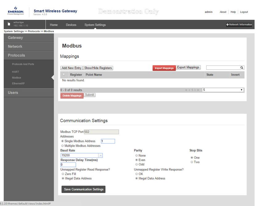
5.4 Modbus . . . . . . . . . . . . . . . . . . . . . . . . . . . . . . . . . . . . . . . . . . . . . . . . . . . . . . . . . . . . . .39
5.4.1 Communication settings. . . . . . . . . . . . . . . . . . . . . . . . . . . . . . . . . . . . . . . . . .39
5.4.2 Register mapping . . . . . . . . . . . . . . . . . . . . . . . . . . . . . . . . . . . . . . . . . . . . . . . .41
5.5 EtherNet/IP . . . . . . . . . . . . . . . . . . . . . . . . . . . . . . . . . . . . . . . . . . . . . . . . . . . . . . . . . . .45
6Section 6: Troubleshooting
6.1 Service support. . . . . . . . . . . . . . . . . . . . . . . . . . . . . . . . . . . . . . . . . . . . . . . . . . . . . . . .49
6.2 Return of materials . . . . . . . . . . . . . . . . . . . . . . . . . . . . . . . . . . . . . . . . . . . . . . . . . . . .52
6.3 Product recycling/disposal . . . . . . . . . . . . . . . . . . . . . . . . . . . . . . . . . . . . . . . . . . . . . .52
7Section 7: Glossary
AAppendix A: Specifications and Reference Data
A.1 Functional specifications . . . . . . . . . . . . . . . . . . . . . . . . . . . . . . . . . . . . . . . . . . . . . . .55
A.1.1 Input power . . . . . . . . . . . . . . . . . . . . . . . . . . . . . . . . . . . . . . . . . . . . . . . . . . . . .55
A.1.2 PoE. . . . . . . . . . . . . . . . . . . . . . . . . . . . . . . . . . . . . . . . . . . . . . . . . . . . . . . . . . . . .55
A.1.3 Current draw . . . . . . . . . . . . . . . . . . . . . . . . . . . . . . . . . . . . . . . . . . . . . . . . . . . .55
A.1.4 Radio frequency power output from antenna . . . . . . . . . . . . . . . . . . . . . . . .55
A.1.5 Environmental . . . . . . . . . . . . . . . . . . . . . . . . . . . . . . . . . . . . . . . . . . . . . . . . . . .55
A.1.6 EMC performance . . . . . . . . . . . . . . . . . . . . . . . . . . . . . . . . . . . . . . . . . . . . . . . .55
A.1.7 Antenna options . . . . . . . . . . . . . . . . . . . . . . . . . . . . . . . . . . . . . . . . . . . . . . . . .55
A.2 Physical specifications . . . . . . . . . . . . . . . . . . . . . . . . . . . . . . . . . . . . . . . . . . . . . . . . . .55
A.2.1 Weight . . . . . . . . . . . . . . . . . . . . . . . . . . . . . . . . . . . . . . . . . . . . . . . . . . . . . . . . .55
A.2.2 Material of construction . . . . . . . . . . . . . . . . . . . . . . . . . . . . . . . . . . . . . . . . . .55
iv Contents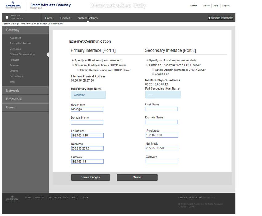
Reference Manual                                                                                                                                          Contents
00809-0200-4420, Rev HC                                                                                                                                       July 2015

                          A.3 Communication specifications . . . . . . . . . . . . . . . . . . . . . . . . . . . . . . . . . . . . . . . . . .56
                                A.3.1 Isolated RS485. . . . . . . . . . . . . . . . . . . . . . . . . . . . . . . . . . . . . . . . . . . . . . . . . . .56
                                A.3.2 Ethernet . . . . . . . . . . . . . . . . . . . . . . . . . . . . . . . . . . . . . . . . . . . . . . . . . . . . . . . .56
                                A.3.3 Modbus. . . . . . . . . . . . . . . . . . . . . . . . . . . . . . . . . . . . . . . . . . . . . . . . . . . . . . . . .56
                                A.3.4 OPC . . . . . . . . . . . . . . . . . . . . . . . . . . . . . . . . . . . . . . . . . . . . . . . . . . . . . . . . . . . .56
                                A.3.5 EtherNet/IP . . . . . . . . . . . . . . . . . . . . . . . . . . . . . . . . . . . . . . . . . . . . . . . . . . . . .56
                          A.4 Self-organizing network specifications . . . . . . . . . . . . . . . . . . . . . . . . . . . . . . . . . . .56
                                A.4.1 Protocol . . . . . . . . . . . . . . . . . . . . . . . . . . . . . . . . . . . . . . . . . . . . . . . . . . . . . . . .56
                                A.4.2 Maximum network size . . . . . . . . . . . . . . . . . . . . . . . . . . . . . . . . . . . . . . . . . . .56
                                A.4.3 Supported device update rates . . . . . . . . . . . . . . . . . . . . . . . . . . . . . . . . . . . .56
                                A.4.4 Network size/latency . . . . . . . . . . . . . . . . . . . . . . . . . . . . . . . . . . . . . . . . . . . . .56
                                A.4.5 Data reliability . . . . . . . . . . . . . . . . . . . . . . . . . . . . . . . . . . . . . . . . . . . . . . . . . . .56
                          A.5 System security specifications . . . . . . . . . . . . . . . . . . . . . . . . . . . . . . . . . . . . . . . . . . .56
                                A.5.1 Ethernet . . . . . . . . . . . . . . . . . . . . . . . . . . . . . . . . . . . . . . . . . . . . . . . . . . . . . . . .56
                                A.5.2 Smart Wireless Gateway access . . . . . . . . . . . . . . . . . . . . . . . . . . . . . . . . . . . .56
                                A.5.3 Self-organizing network . . . . . . . . . . . . . . . . . . . . . . . . . . . . . . . . . . . . . . . . . .56
                                A.5.4 Internal firewall . . . . . . . . . . . . . . . . . . . . . . . . . . . . . . . . . . . . . . . . . . . . . . . . . .56
                                A.5.5 Third party certification . . . . . . . . . . . . . . . . . . . . . . . . . . . . . . . . . . . . . . . . . . .56
                          A.6 Dimensional drawings. . . . . . . . . . . . . . . . . . . . . . . . . . . . . . . . . . . . . . . . . . . . . . . . . .57
                                A.6.1 Remote omni-antenna kit . . . . . . . . . . . . . . . . . . . . . . . . . . . . . . . . . . . . . . . . .58
                          A.7 Ordering information . . . . . . . . . . . . . . . . . . . . . . . . . . . . . . . . . . . . . . . . . . . . . . . . . .59
                          A.8 Accessories and spare parts . . . . . . . . . . . . . . . . . . . . . . . . . . . . . . . . . . . . . . . . . . . . .60

                  BAppendix B: Product Certifications
                          B.1 European Directive Information . . . . . . . . . . . . . . . . . . . . . . . . . . . . . . . . . . . . . . . . .61
                          B.2 Telecommunication Compliance . . . . . . . . . . . . . . . . . . . . . . . . . . . . . . . . . . . . . . . .61
                          B.3 FCC and IC . . . . . . . . . . . . . . . . . . . . . . . . . . . . . . . . . . . . . . . . . . . . . . . . . . . . . . . . . . . .61
                          B.4 Ordinary Location Certification . . . . . . . . . . . . . . . . . . . . . . . . . . . . . . . . . . . . . . . . . .61
                          B.5 Installing Equipment in North America . . . . . . . . . . . . . . . . . . . . . . . . . . . . . . . . . . .61
                                B.5.1 USA . . . . . . . . . . . . . . . . . . . . . . . . . . . . . . . . . . . . . . . . . . . . . . . . . . . . . . . . . . . .61
                                B.5.2 Canada . . . . . . . . . . . . . . . . . . . . . . . . . . . . . . . . . . . . . . . . . . . . . . . . . . . . . . . . .61
                                B.5.3 Europe. . . . . . . . . . . . . . . . . . . . . . . . . . . . . . . . . . . . . . . . . . . . . . . . . . . . . . . . . .62
                                B.5.4 International . . . . . . . . . . . . . . . . . . . . . . . . . . . . . . . . . . . . . . . . . . . . . . . . . . . .62
                                B.5.5 Brazil . . . . . . . . . . . . . . . . . . . . . . . . . . . . . . . . . . . . . . . . . . . . . . . . . . . . . . . . . . .62
                                B.5.6 China . . . . . . . . . . . . . . . . . . . . . . . . . . . . . . . . . . . . . . . . . . . . . . . . . . . . . . . . . . .62
                                B.5.7 Japan . . . . . . . . . . . . . . . . . . . . . . . . . . . . . . . . . . . . . . . . . . . . . . . . . . . . . . . . . . .62
                                B.5.8 EAC – Belarus, Kazakhstan, Russia . . . . . . . . . . . . . . . . . . . . . . . . . . . . . . . . . .62
                                B.5.9 Combinations . . . . . . . . . . . . . . . . . . . . . . . . . . . . . . . . . . . . . . . . . . . . . . . . . . .62

Contents                                                                                                                                                               v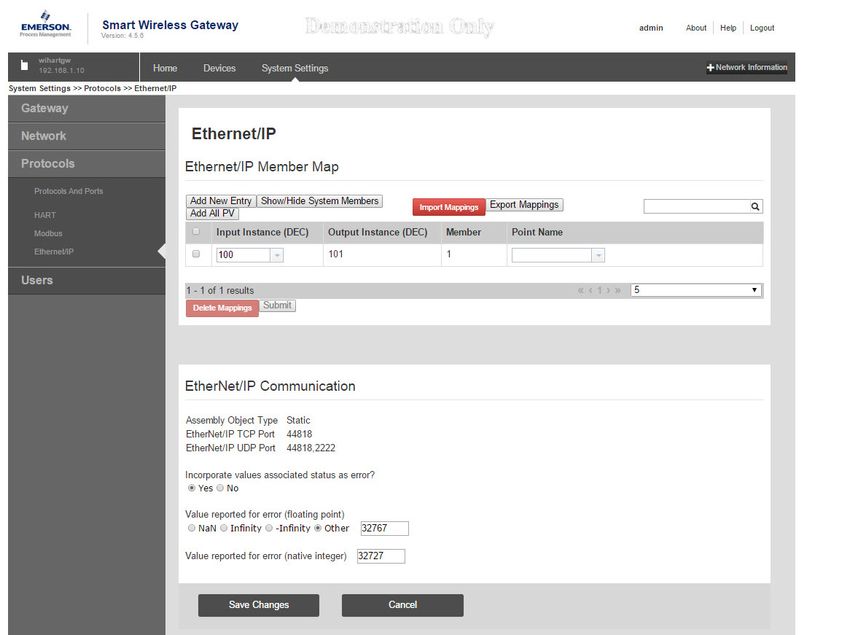
Contents                                                                                                                          Reference Manual
July 2015                                                                                                                     00809-0200-4420, Rev HC

            CAppendix C: DeltaV Ready
                C.1 Overview . . . . . . . . . . . . . . . . . . . . . . . . . . . . . . . . . . . . . . . . . . . . . . . . . . . . . . . . . . . . .63
                C.2 Latency considerations in control logic design and operation. . . . . . . . . . . . . . . .63
                C.3 Requirements . . . . . . . . . . . . . . . . . . . . . . . . . . . . . . . . . . . . . . . . . . . . . . . . . . . . . . . . .64
                      C.3.1 DeltaV . . . . . . . . . . . . . . . . . . . . . . . . . . . . . . . . . . . . . . . . . . . . . . . . . . . . . . . . . .64
                      C.3.2 Smart Wireless Gateway . . . . . . . . . . . . . . . . . . . . . . . . . . . . . . . . . . . . . . . . . .64
                C.4 Mounting and connecting . . . . . . . . . . . . . . . . . . . . . . . . . . . . . . . . . . . . . . . . . . . . . .64
                C.5 Setup . . . . . . . . . . . . . . . . . . . . . . . . . . . . . . . . . . . . . . . . . . . . . . . . . . . . . . . . . . . . . . . .65

            DAppendix D: Redundancy
                D.1 Overview . . . . . . . . . . . . . . . . . . . . . . . . . . . . . . . . . . . . . . . . . . . . . . . . . . . . . . . . . . . . .69
                D.2 Requirements . . . . . . . . . . . . . . . . . . . . . . . . . . . . . . . . . . . . . . . . . . . . . . . . . . . . . . . . .69
                      D.2.1 Smart Wireless Gateway . . . . . . . . . . . . . . . . . . . . . . . . . . . . . . . . . . . . . . . . . .69
                      D.2.2 Host system . . . . . . . . . . . . . . . . . . . . . . . . . . . . . . . . . . . . . . . . . . . . . . . . . . . . .69
                D.3 Setup . . . . . . . . . . . . . . . . . . . . . . . . . . . . . . . . . . . . . . . . . . . . . . . . . . . . . . . . . . . . . . . .70
                D.4 Mounting and connections . . . . . . . . . . . . . . . . . . . . . . . . . . . . . . . . . . . . . . . . . . . . .73
                      D.4.1 Mounting . . . . . . . . . . . . . . . . . . . . . . . . . . . . . . . . . . . . . . . . . . . . . . . . . . . . . . .73
                      D.4.2 Ethernet . . . . . . . . . . . . . . . . . . . . . . . . . . . . . . . . . . . . . . . . . . . . . . . . . . . . . . . .73
                      D.4.3 Simplex RS-485 . . . . . . . . . . . . . . . . . . . . . . . . . . . . . . . . . . . . . . . . . . . . . . . . . .74
                      D.4.4 Dual RS-485 . . . . . . . . . . . . . . . . . . . . . . . . . . . . . . . . . . . . . . . . . . . . . . . . . . . . .75
                      D.4.5 Power . . . . . . . . . . . . . . . . . . . . . . . . . . . . . . . . . . . . . . . . . . . . . . . . . . . . . . . . . .75
                D.5 Diagnostics . . . . . . . . . . . . . . . . . . . . . . . . . . . . . . . . . . . . . . . . . . . . . . . . . . . . . . . . . . .76
                D.6 Gateway replacement . . . . . . . . . . . . . . . . . . . . . . . . . . . . . . . . . . . . . . . . . . . . . . . . . .78

vi                                                                                                                                                    Contents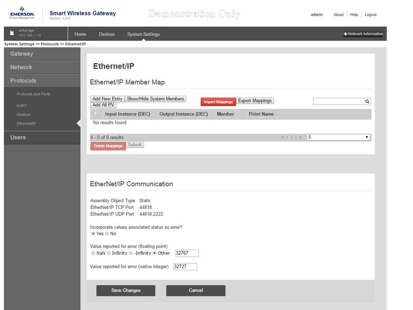
Reference Manual                                                                       Smart Wireless Gateway
00809-0200-4420, Rev HC                                                                                   July 2015

                    Emerson™ Smart Wireless Gateway

                     NOTICE
                      Read this manual before working with the product. For personal and system safety, and for
                      optimum product performance, make sure you thoroughly understand the Contents before
                      installing, using, or maintaining this product.
                      Within the United States, Emerson Process Management has two toll-free assistance
                      numbers:
                      Global Service Center
                      Software and Integration Support
                      1-800-833-8314 (United States)
                      +63-2-702-1111 (International)
                      Customer Central
                      Technical support, quoting, and order-related questions.
                      1-800-999-9307 (7:00 am to 7:00 pm CST)
                      North American Response Center
                      Equipment service needs.
                      1-800-654-7768 (24 hours—includes Canada)
                      Outside of the United States, contact your local Emerson Process Management
                      representative.

                                                                                                                  vii
Smart Wireless Gateway Reference Manual
July 2015 00809-0200-4420, Rev HC
Failure to follow these installation guidelines could result in death or serious injury.
Make sure only qualified personnel perform the installation.
Explosions could result in death or serious injury.
Verify the operating atmosphere of the device is consistent with the appropriate
hazardous locations certifications.
Electrostatic discharge can damage electronics.
Use proper personal grounding before handling electronics or making contact with
leads and terminals.
Electrical shock could cause death or serious injury.
If the device is installed in a high-voltage environment and a fault condition or
installation error occurs, high voltage may be present on transmitter leads and
terminals.
Use extreme caution when making contact with the leads and terminals.
This device complies with Part 15 of the FCC Rules. Operation is subject to the
following conditions:
This device may not cause harmful interference.
This device must accept any interference received, including interference that may
cause undesired operation.
This device must be installed to ensure a minimum antenna separation distance of 20
cm from all persons.
The products described in this document are NOT designed for nuclear-qualified
applications. Using non-nuclear qualified products in applications that require
nuclear-qualified hardware or products may cause inaccurate readings.
For information on Rosemount nuclear-qualified products, contact your local Emerson
Process Management Sales Representative.
viii
Reference Manual Section 1: Introduction
00809-0200-4420, Rev HC July 2015
Section 1 Introduction
1.1 Product overview
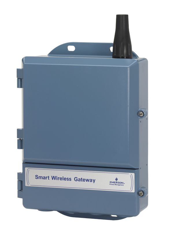
The Smart Wireless Gateway connects WirelessHART® self-organizing networks with host
systems and data applications. Modbus® communications over RS-485 or Ethernet LAN provide
universal integration and system interoperability. The optional OPC functionality from the
Gateway offers a means to connect to newer systems and applications while providing a richer
set of data.
The Smart Wireless Gateway provides industry leading security, scalability, and data reliability.
Layered security ensures that the network stays protected. Additional devices can be added at
anytime. There is no need to configure communication paths because the Gateway manages
the network automatically. This feature also ensures that WirelessHART field devices have the
most reliable path to send data.
What is included?
The box containing the Smart Wireless Gateway contains several items essential to the
complete installation and operation of the Gateway.
Smart Wireless Gateway
Quick Start Guide
Software pack, 2 disk set
Mounting hardware
Conduit plugs, 4
Conduit adapters (optional)
If an optional remote antenna has been ordered, it will be in a separate box containing:
Remote mount antenna
Mounting hardware
Lightning arrestor
Cable [1 or 2 pieces that total 50 ft, (15,2 m) in length]
Coaxial sealant
Introduction 1
Section 1: Introduction                                                                         Reference Manual
July 2015                                                                                     00809-0200-4420, Rev HC

1.2              Using this manual
                 This manual will help to install, configure, operate, and maintain the Gateway.

                 Section 1: Introduction
                 This section introduces the product and describes what components may be found in the box. It
                 also includes details for services and support as well as return and disposal of the product.

                 Section 2: Configuration
                 This section describes how to connect to the Gateway for the first time and what settings should
                 be configured before placing it on a live control network. It is important to note that some
                 Gateways are used in stand-alone applications and do not reside on a network. In these cases, it
                 is still important to configure the items outlined in this section.

                 Section 3: Installation
                 This section describes how to properly mount the Gateway and make electrical connections,
                 including electrical wiring, grounding, and host system connections. This section also describes
                 how to mount the optional remote antenna.

                 Section 4: Commissioning
                 This section describes the installation and setup of the optional software included with the
                 Smart Wireless Gateway. This software will aid in secure host integration as well as wireless field
                 device configuration.

                 Section 5: Operation and Maintenance
                 This section describes how to connect the Gateway to a host system and integrate data
                 gathered from the field device network. It covers network architectures, security, and data
                 mapping.

                 Section 6: Troubleshooting
                 This section provides troubleshooting tips as well as information to contact technical support
                 over the phone or through email.
                 Section 7: Glossary
                 The glossary defines terms used throughout this manual or that appear in the web interface of
                 the Smart Wireless Gateway.

                 Appendices

                 The appendices provide additional and more specific information on a variety of subjects
                 including Specifications and Reference Data and Product Certifications.

2                                                                                                      Introduction
Reference Manual Section 2: Configuration
00809-0200-4420, Rev HC July 2015
Section 2 Configuration
Overview . . . . . . . . . . . . . . . . . . . . . . . . . . . . . . . . . . . . . . . . . . . . . . . . . . . . . . . . . . . . . . . . . . page 3
System requirements . . . . . . . . . . . . . . . . . . . . . . . . . . . . . . . . . . . . . . . . . . . . . . . . . . . . . . . . page 3
Initial setup . . . . . . . . . . . . . . . . . . . . . . . . . . . . . . . . . . . . . . . . . . . . . . . . . . . . . . . . . . . . . . . . page 4
2.1 Overview
This section describes how to connect to the Gateway for the first time and what settings should
be configured before placing it on a live control network. It is important to note that some
Gateways are used in stand-alone applications and do not reside on a network. In these cases, it
is still important to configure the items outlined in this section.
Before the Gateway can be permanently mounted and connected to a live control network, it
needs to be configured with an IP address. This is done by forming a private network between
the gateway and a PC/laptop. The following items are needed to complete this section:
Gateway
PC/laptop
24 VDC (nominal) power supply
Note
If the Gateway was ordered with the DeltaV™ Ready option, it has been configured to operate on
a DeltaV control network, and the Initial Configuration Section does not need to be completed.
Only setting the password is required.
2.2 System requirements
The following requirements apply to the PC/laptop used to configure the Gateway. Additional
requirements may apply if using the optional Security Setup Utility or AMS® Wireless
Configurator. See Section 4: Commissioning for more information.
Web browser applications
Mozilla Firefox® 1.5 or higher
Microsoft® Internet Explorer® 7.0 or higher
Ethernet
10/100BaseTX Ethernet communication protocol
Configuration 3Section 2: Configuration Reference Manual
July 2015 00809-0200-4420, Rev HC
2.3 Initial setup
Note
For information on connecting a Windows™ 7 PC, see the technical note (document number
00840-0900-4420).
2.3.1 Prepare PC/laptop
The PC/laptop will need to be configured to form a private network before communicating to
the Gateway. The network settings can be found in the control panel of the PC/laptop. To
configure these settings:
1. Find and open the Control Panel (Generally found from the Start Menu).
2. Open Network Connections.
3. Select Local Area Connection or Network and Sharing Center.
4. Right click the mouse and select Properties from the list.
5. Select Internet Protocol (TCP/IP), then select Properties.
6. From the General tab, select Use the following IP address.
7. Set the IP Address to “192.168.1.12” and select Tab.
8. A Subnet mask of 255.255.255.0 should fill in automatically.
9. Select OK to close the Internet Protocol (TCP/IP) window.
10. Select Close on the Local Area Connection window.
Internet proxies will need to be disabled through the PC/laptop’s default internet browser.
1. Find and open the default internet browser (typically Microsoft Internet Explorer).
2. From the Tools menu, select Internet Options.
3. From the Connections tab, select LAN Settings.
4. Under Proxy Server, verify the boxes for Automatically Detect Settings and Use a proxy
server for your LAN are unchecked.
5. Select OK to close the Local Area Network (LAN) Settings window.
6. Select OK to close the Internet Options window.
The PC/laptop is now set up to form a private network and to communicate with the Gateway.
Note
Connecting to the Gateway's secondary Ethernet port will require different network settings.
See Table 2-1 for additional network settings.
4 ConfigurationReference Manual Section 2: Configuration
00809-0200-4420, Rev HC July 2015
Table 2-1. Default IP Addresses
Gateway PC/laptop Subnet
Ethernet 1 192.168.1.10 192.168.1.12 255.255.255.0
Ethernet 2 192.168.2.10 192.168.2.12 255.255.255.0
Ethernet 1 (DeltaV Ready) 10.5.255.254 10.5.255.200 255.254.0.0
Ethernet 2 (DeltaV Ready) 10.9.255.254 10.9.255.200 255.254.0.0
2.3.2 Connections and power
Physically connect the PC/laptop to the Gateway by connecting one end to the Ethernet port on
the back of the PC/laptop. Connect the other end to the Ethernet 1 port on the Gateway.
Figure 2-1 shows the standard terminal block diagram. Once the Gateway and PC/laptop are
connected, wire a 24 VDC (nominal) power supply with a capacity of at least 250 mA to the
Gateway power input terminals.
Determining Gateway compatibility with PoE
Figure 2-1. Legacy Gateway Terminal Block
24 VDC
(nominal) Serial
Power Input Modbus Not Used Not Used
+ - S A B + - S S - +
Case
+ - S S - +
Ethernet 2
with Power Ethernet 2 Ethernet 1 Not Used Not Used
(Covered) (Secondary) (Primary)
Figure 2-2. PoE Compatible Gateway Terminal Block
24 VDC
(nominal) Serial
Power Input Modbus
+ - S A B Ethernet 2 Ethernet 1
Case (Secondary) (Primary)
Configuration 5Section 2: Configuration Reference Manual
July 2015 00809-0200-4420, Rev HC
When making physical connections to the Gateway it is important to use the electrical
conduit entries located on the bottom of the housing. Connecting through the open
terminal block cover (the lower cover) may stress the connections and damage the
Gateway.
Power over Ethernet (PoE)
This Gateway is equipped with PoE technology to allow it to source power to a compatible
device over the connecting Ethernet cable (PSE mode) or derive its power from another PoE
device via the Ethernet connection (PD mode). This device complies with the IEEE 802.3at-2009
standard for PSE operation and IEEE 802.3af-2003 or IEEE 802.3at -2009 for PD operation. These
standards require the use of Category 5 Ethernet cable or higher.
In the operation of IEEE 802.3a, PoE power is only transmitted from one device to another when
the proper impedance match is made. This prevents damage to non PoE devices on the
network. In the Gateway, power is transmitted in passive mode over two unused differential
pairs of the Ethernet cable. To use this feature, the Gateway must be connected over the
Ethernet to a matching IEEE 802.3a device. Failure to do this will cause no power to be sent or
sourced.
A set of switches on the power supply board allow the selection of the specific Ethernet port for
PoE and the selection of whether it is a PSE (Power Sourcing Equipment) sourcing power or a PD
(Powered Device) deriving its power from another IEEE 802.9 PSE device. See Figure 2-3 for the
switch diagram required for PoE configuration.
Note
The Gateway can either source or receive power over an Ethernet port; it cannot do both at the
same time.
If using the Gateway as a PSE, the total additional power requirements of the PD must be
factored into the total input power requirements of the power supply for the Gateway. It is
recommended that the power selection mode switch be left in the PD position unless PSE is
needed.
6 ConfigurationReference Manual Section 2: Configuration
00809-0200-4420, Rev HC July 2015
Figure 2-3. 1420 PoE Jumpering
Traditionally Powered Gateway
ETH1 ETH2 PSE Input Power
10.5V-30V Modbus
S A B
Case
Ethernet 2 Ethernet 1 To Host
PD PSE PD PSE
DIS
EN Power
PoE, Gateway as a PD via Ethernet Port 2
ETH1 ETH2 PSE
Input Power
10.5V-30V Modbus
S A B
Case
Ethernet 2 Ethernet 1 To Host
PD PSE PD PSE
DIS
EN
From PSE Device
Data Power
PoE, Gateway as a PSE via Ethernet Port 2
ETH1 ETH2 PSE Input Power
10.5V-30V Modbus
S A B
Case
Ethernet 2 Ethernet 1
To Host
PD PSE PD PSE Power
DIS
EN
To POE Device
Power
Data
Legend:
ETH1: Ethernet port 1 selected for PD or PSE
ETH2: Ethernet port 2 selected for PD or PSE
PD: Gateway derives power from the Ethernet port selected
PSE: Gateway derives power from a local power supply and sends power down the Ethernet port selected to another device
EN: Enabled; this enables the PSE operation
DIS: Disabled; this disables the PSE operation
Note
Only one port and one mode of operation (PD or PSE) can be selected at a time; any other
combination of jumpers is invalid.
Note
IEEE 802.3af-2003 PoE standard provides up to 15.4 W of DC power (minimum 44 V DC and 350
mA) to each device. Only 12.95 W is assured to be available at the powered device as some
power is dissipated in the cable.
IEEE 802.3at-2009 PoE standard also known as “PoE+” or “PoE plus”, provides up to 25.5 W of
power. The 2009 standard prohibits a powered device from using all four pairs for power.
For more information on PoE and frequently asked questions, reference document number
00870-0500-4420 or Section 3.4.6.
In order to use both ports for PoE, remember to order option code “2” when selecting number
of Ethernet ports.
Configuration 7Section 2: Configuration Reference Manual
July 2015 00809-0200-4420, Rev HC
2.3.3 Configure the Gateway
It is now possible to log into the Gateway for the first time and begin configuration for
placement on a live control network. The following items need to be configured:
Security passwords
Time settings
TCP/IP network settings
Use the following procedure to log in to the Gateway:
1. Open a standard web browser (typically Microsoft Internet Explorer).
2. Enter “192.168.1.10” in the address bar.
3. Acknowledge the security to proceed.
4. In the User Name field, enter “admin”.
5. In the Password field, enter “default”.
The web browser will now be directed to the Gateway’s default home page. There is a navigation
menu located on the left hand side with four main areas.
Diagnostics: view status of communications, client server parameters, and more
Monitor: screens created by the user to view data from field devices
Explorer: basic view of values from field devices
Setup: configure the Gateway for operations, security, and host system integration
Security passwords
There are four-role based user accounts for the gateway with varying levels of access. The table
below describes this access.
Table 2-2. Role Based Access User Accounts
Role User name Web interface access
Executive exec Read-only access
Operator oper Read-only access
Maintenance maint Configure HART® device settings
Configure Modbus® communications
Configure Modbus register mapping
Configure OPC browse tree
Configure Active Advertising
Administrator admin Includes all maintenance privileges
Configure Ethernet network settings
Configure WirelessHART® network settings
Set passwords
Set time settings
Set home page options
Configure custom point pages
Restart applications
8 ConfigurationReference Manual Section 2: Configuration
00809-0200-4420, Rev HC July 2015
Each of the initial passwords for the user accounts is default. It is recommended, for security
purposes, that these passwords are changed. The administrator password should be
appropriately noted when changed. If it is lost, contact Emerson™ Process Management for
technical support.
To change the User Accounts Passwords:
1. Navigate to System Settings>Users>User options.
2. Click Edit.
3. Set the new password for each role based user account, and confirm.
4. Click Submit.
Note
It is suggested that the default security settings in System Settings>Users>User options be
changed to the local IT best practices or the Normal setting after initial login. Strong or custom
settings are available for more robust passwords. For more information on this screen and
others, see the User Interface Terminology Guide (document number 00809-0600-4420).
Time settings
The Gateway is the timekeeper for the WirelessHART network, so it is imperative that the
Gateway’s time is accurate for timestamp data to be meaningful. Time settings can be found by
navigating to System Settings>Gateway>Time.
There are three ways to set the Gateway time:
Network Time Protocol (recommended)
This option uses a Network Time Protocol (NTP) server to adjust the Gateway’s time in
order to match the time of the control network. Enter the IP address for the NTP server
and select the packet version (1, 2, 3, or 4).
Set with PC Time
This option will match the Gateway’s time to that of the PC/laptop.
Manual Entry
This option allows the user to enter a specific date (MM:DD:YY) and time (HH:MM:SS).
Note
Network Time Protocol (NTP) is recommended for the best network performance because it
always adjusts time to match the network time server.
Configuration 9Section 2: Configuration Reference Manual
July 2015 00809-0200-4420, Rev HC
Figure 2-4. Time Settings
TCP/IP network settings
Use caution when making changes to the TCP/IP network settings. If they are lost or
improperly configured, it may be impossible to log into the Gateway. Contact the network
administrator for information on the proper TCP/IP network settings to apply.
Prior to the gateway being installed and connected to a live control network, it should be
configured with an IP address, as well as other TCP/IP network settings.
Request the following configuration items from the network administrator:
Specify an IP address, or use a DHCP server
Hostname
Domain Name
IP address
Netmask
Gateway
Obtaining an IP address from a DHCP server is not recommended, since the Gateway operation
will be dependent upon the availability of the DHCP server. For maximum gateway availability it
is best practice to specify an IP address.
10 ConfigurationReference Manual Section 2: Configuration
00809-0200-4420, Rev HC July 2015
To change the TCP/IP Network Settings:
1. Navigate to System Settings>Gateway>Ethernet Communication.
2. Select Specify an IP address (recommended).
3. Enter the following:
Hostname
Domain Name
IP Address
Netmask
Gateway
4. Click Save Changes.
5. When prompted, click Restart apps.
6. Click Yes to confirm restart.
7. Close the web browser.
Note
Once the IP Address of the Gateway has been changed, communications to the web interface
will be lost. Restart the web browser, then log back into the Gateway using the new IP address
and other TCP/IP network settings. The PC/laptop TCP/IP network settings may need to be
changed.
Configuration 11Section 2: Configuration Reference Manual
July 2015 00809-0200-4420, Rev HC
Figure 2-5. Ethernet Settings
2.3.4 System backup
The Gateway has a System Backup and Restore feature that saves all user-configured data. It is
best practice that a System Backup be performed periodically throughout the installation and
configuration process.
1. Navigate to System Settings>Gateway>Backup And Restore.
2. Select Save Backup.
3. The Gateway collects the configuration date and when the file download pop up
appears, click Save.
4. Enter a save location and file name.
5. Select Save.
6. Click Return to form.
Note
System backup contains user passwords and keys used for encrypting communication. Store
downloaded system backups in a secure location. These files themselves are also encrypted.
12 ConfigurationReference Manual Section 3: Installation
00809-0200-4420, Rev HC July 2015
Section 3 Installation
Overview . . . . . . . . . . . . . . . . . . . . . . . . . . . . . . . . . . . . . . . . . . . . . . . . . . . . . . . . . . . . . . . . . . page 13
Mounting . . . . . . . . . . . . . . . . . . . . . . . . . . . . . . . . . . . . . . . . . . . . . . . . . . . . . . . . . . . . . . . . . . page 14
Remote antenna (optional) . . . . . . . . . . . . . . . . . . . . . . . . . . . . . . . . . . . . . . . . . . . . . . . . . . . page 16
Connecting . . . . . . . . . . . . . . . . . . . . . . . . . . . . . . . . . . . . . . . . . . . . . . . . . . . . . . . . . . . . . . . . page 19
3.1 Overview
This section describes how to properly mount the Gateway and make electrical connections,
including electrical wiring, grounding, and host system connections. This section also describes
how to mount the optional remote antenna.
3.1.1 General considerations
The Smart Wireless Gateway may be mounted in any general purpose location. Be sure the
covers are secured tightly to prevent exposure of any electronics to moisture and
contamination.
The Gateway should be mounted in a location that allows convenient access to the host system
network (process control network) as well as the wireless field device network.
3.1.2 Physical description
For dimensional drawing information refer to Appendix B: Product Certifications. The cast
aluminum housing encloses the electronics circuitry of the Gateway. The front of the enclosure
has an upper cover and a junction box cover. The upper cover provides access to the electronics
and radio. The junction box cover provides access to the terminal block.
To open either cover, use a ¼-in. bladed screwdriver to remove the appropriate screw on the
unhinged side of the enclosure.
Installation 13Section 3: Installation Reference Manual
July 2015 00809-0200-4420, Rev HC
3.2 Mounting
Find a location where the Gateway has optimal wireless performance. Ideally this will be 15-25
ft. (4,6 - 7,6 m) above the ground or 6 ft. (2 m) above obstructions or major infrastructure.
Figure 3-1 shows an example gateway installation.
Figure 3-1. Gateway Installation
C
6 ft. (2 m)
B
A E
15-25 ft.
D (4,6-7,6 m)
A. Control Room D. Mast or Pipe
B. Ground E. Infrastructure
C. Gateway
14 InstallationReference Manual Section 3: Installation
00809-0200-4420, Rev HC July 2015
3.2.1 Pipe mount
The following hardware and tools are needed to mount the Gateway to a 2-in. pipe:
Two 5/16-in. u-bolts (supplied with Gateway)
2-in. mounting pipe
½-in. socket-head wrench
Mount the Gateway using the following procedure:
1. Insert one u-bolt around the pipe, through the top mounting holes of the Gateway
enclosure, and through the washer plate.
2. Use a 1/2-in. socket-head wrench to fasten the nuts to the u-bolt.
3. Repeat for the second u-bolt and the lower mounting holes.
Figure 3-2. Pipe Mount
3.2.2 Bracket mount (alternate)
The following hardware and tools are needed to mount the Gateway to a support bracket:
Four 15/16-in. bolts
Mounting support bracket
/8-in. drill
3
/2 -in. socket-head wrench
1
Mount the Gateway using the following procedure:
1. Drill four 3/8-in. (9,525 mm) holes spaced 3.06-in. (77 mm) apart horizontally and
11.15-in. (283 mm) apart vertically in the support bracket, corresponding with the
holes on the Gateway enclosure.
2. Using a 1/2-in. socket-head wrench, attach the Gateway to the support bracket with four
15
/16-in. bolts.
Installation 15Section 3: Installation Reference Manual
July 2015 00809-0200-4420, Rev HC
3.3 Remote antenna (optional)
The remote antenna options provide flexibility for mounting the Gateway based on wireless
connectivity, lightning protection, and current work practices.
When installing remote mount antennas for the Smart Wireless Gateway, always use
established safety procedures to avoid falling or contact with high-power electrical lines.
Install remote antenna components for the Smart Wireless Gateway in compliance with
local and national electrical codes and use best practices for lightning protection.
Before installing consult with the local area electrical inspector, electrical officer, and work
area supervisor.
The Smart Wireless Gateway remote antenna option is specifically engineered to provide
installation flexibility while optimizing wireless performance and local spectrum approvals.
To maintain wireless performance and avoid non-compliance with spectrum regulations,
do not change the length of cable or the antenna type.
If the supplied remote mount antenna kit is not installed per these instructions, Emerson™
Process Management is not responsible for wireless performance or non-compliance with
spectrum regulations.
The remote mount antenna kit includes coaxial sealant for the cable connections for the
lightning arrestor and antenna.
Find a location where the remote antenna has optimal wireless performance. Ideally this will be
15-25 ft (4,6 - 7,6 m) above the ground or 6 ft (2 m) above obstructions or major infrastructure.
To install the remote antenna use one of the following procedures:
Installation of WL2/WN2 option (outdoor applications)
1. Mount the antenna on a 1.5-2 inch pipe mast using the supplied mounting equipment.
2. Connect the lightning arrestor directly to the top of the Gateway.
3. Install the grounding lug, lock washer, and nut on top of the lightning arrestor.
4. Connect the antenna to the lightning arrestor using the supplied coaxial cable ensuring
the drip loop is not closer than 1 foot (0,3 m) from the lightning arrestor.
5. Use the coaxial sealant to seal each connection between the wireless field device,
lightning arrestor, cable, and antenna.
6. Ensure the mounting mast, lightning arrestor, and Gateway are grounded according to
local/national electrical code.
Note
Any spare lengths of coaxial cable should be placed in 12 inch (0,3 m) coils.
16 InstallationReference Manual Section 3: Installation
00809-0200-4420, Rev HC July 2015
Figure 3-3. Installation of WL2/WN2 Option
B
C
D
A
E
F
G G
H
A. Control Building E. Lightning Arrestor
B. Remote Antenna F. Gateway
C. Cable G. Ground
D. Drip Loop H. Earth
Installation of WL3/WL4 Option (indoor to outdoor
applications)
1. Mount the antenna on a 1.5-2 inch pipe mast using the supplied mounting equipment.
2. Mount the lightning arrestor near the building egress.
3. Install the grounding lug, lock washer, and nut on top of lightning arrestor.
4. Connect the antenna to the lightning arrestor using the supplied coaxial cable ensuring
the drip loop is not closer than 1 foot (0,3 m) from the lightning arrestor.
5. Connect the lightning arrestor to the Gateway using the supplied coaxial cable.
6. Use the coaxial sealant to seal each connection between the Gateway, lightning
arrestor, cable, and antenna.
7. Ensure that the mounting mast, lightning arrestor, and Gateway are grounded
according to local/national electrical codes.
Note
Any spare lengths of coaxial cable should be placed in 12 inch (0,3 m) coils.
Installation 17Section 3: Installation Reference Manual
July 2015 00809-0200-4420, Rev HC
Figure 3-4. Installation of WL3/WL4 Option
B
C
A
D
F E
G G
H
A. Control Building E. Lightning Arrestor
B. Remote Antenna F. Gateway
C. Cable G. Ground
D. Drip Loop H. Earth
Note: Weather proofing is required!
The remote mount antenna kit includes coaxial sealant for the cable connections for the
lightning arrestor, antenna, and Gateway. The coaxial sealant must be applied to guarantee
performance of the wireless field network. See Figure 3-5 for details on how to apply weather
proofing.
Figure 3-5. Applying Coaxial Sealant to Cable Connections
18 InstallationReference Manual Section 3: Installation
00809-0200-4420, Rev HC July 2015
Table 3-1. Remote Antenna Kit Options
Kit option Antenna Cable 1 Cable 2 Lightning arrestor
1
WL2 /2 Wavelength 50 ft. (15,2 m) N/A Head mount, jack to plug
Dipole LMR-400 Gas discharge tube
Omni-Directional 0.5 dB insertion loss
+6 dB Gain
1
WL3 /2 Wavelength 30 ft. (9,1 m) 20 ft. (6,1 m) In-line, jack to jack
Dipole LMR-400 LMR-400 Gas discharge tube
Omni-Directional 0.5 dB insertion loss
+6 dB Gain
1
WL4 /2 Wavelength 40 ft. (12,2 m) 10 ft. (3,0 m) In-line, jack to jack
Dipole LMR-400 LMR-400 Gas discharge tube
Omni-Directional 0.5 dB insertion loss
+6 dB Gain
1
WN2 /2 Wavelength 25 ft. (7,6 m) N/A Head mount, jack to plug
Dipole LMR-400 Gas discharge tube
Omni-Directional 0.5 dB insertion loss
+8 dB Gain
3.4 Connecting
All connections to the Gateway can be made at the terminal block, which is located in the lower
junction box section of the enclosure. The terminal block label is located on the inside of the
lower cover. See Figure 3-6 for the standard terminal block label.
The junction box portion of the enclosure has four conduit entries for power and
communications wiring. Do not run communication wiring in conduit or open trays with power
wiring, or near heavy electrical equipment.
Install the included conduit plugs in any unused conduit openings. For NEMA® 4X and IP65
requirements, use thread seal (PTFE) tape or paste on male threads to provide a watertight seal.
3.4.1 Grounding
The Gateway enclosure case should always be grounded in accordance with national and local
electrical codes. The most effective grounding method is a direct connection to earth ground
with minimal impedance. Ground the Gateway by connecting the external grounding lug to
earth ground. The connection should be 1 Ω or less. The external ground lug is located below
the Gateway enclosure and is identified by the following symbol:
3.4.2 Ethernet
The Gateway is equipped with two 10/100BaseTX Ethernet communications ports (see
Figure 3-6). These connections can be used to access the Gateway’s web interface and to
communicate Modbus TCP and OPC protocols.
The primary Ethernet port (Ethernet 1) is used to connect to the host system or other
application systems. The secondary Ethernet port (Ethernet 2) can be used as a back up
connection or a maintenance port for local access to the Gateway.
Installation 19Section 3: Installation Reference Manual
July 2015 00809-0200-4420, Rev HC
Figure 3-6. Terminal Block Diagram
24 VDC
(nominal) Serial
Power Input Modbus Not Used Not Used
+ - S A B + - S S - +
Case
+ - S S - +
Ethernet 2
with Power Ethernet 2 Ethernet 1 Not Used Not Used
(Covered) (Secondary) (Primary)
Figure 3-7. PoE Compatible Gateway Terminal Block
24 VDC
(nominal) Serial
Power Input Modbus
+ - S A B Ethernet 2 Ethernet 1
Case (Secondary) (Primary)
Ethernet connections should use Cat5E or better shielded cable to connect to an Ethernet hub,
switch, or router. The maximum cable length should not exceed 328 ft. (100 m).
Note
Unless dual Ethernet ports were specified at the time of order, the secondary Ethernet port
(Ethernet 2) will not be active.
3.4.3 RS-485
The Gateway may be ordered with an optional RS-485 (serial) connection (Figure 3-6). It is
referenced by the A and B Serial Modbus terminals. This connection is used to communicate
Modbus RTU on an RS-485 data bus.
Use 18 AWG single twisted shielded pair wiring to connect the Gateway to the RS-485 data bus.
The total bus length should not exceed 4000 ft. (1220 m). Connect the Tx + (positive, transmit)
wire to terminal A and the Rx - (negative, receive) wire to terminal B. The wiring shield should be
trimmed close and insulated from touching the Gateway enclosure or other terminations. Only
terminated at one end typically at the power supply end.
20 InstallationReference Manual Section 3: Installation
00809-0200-4420, Rev HC July 2015
If the existing data bus uses a 4 wire Full Duplex configuration, see Figure 3-8 to convert to a
2-wire Half Duplex configuration.
Figure 3-8. Convert from Full to Half Duplex
Tx
(A)
Rx
Tx
(B)
Rx
3.4.4 Terminating resistors
Three DIP switches are provided to enable various terminating resistors to the RS-485 data bus.
The switches are found inside the electronics housing near the top center of the main circuit
board (Figure 3-9).
Figure 3-9. RS-485 Resistor DIP Switches
DIP Switches
K40
470Ω Pull-down Resistor
Main Circuit Board 3
120Ω Terminating Resistor
2
Radio
ON
470Ω Pull-up Resistor
1
Electronics
Switches 1 and 3 are connected to pull-up and pull down resistors. Switch 1 is for the Tx + (A)
line and Switch 3 is for the Rx – (B) line. These 470Ω resistors are used to prevent noise from
being interpreted as valid communications during periods when no actual communications are
occurring. Only one set of pull-up and pull-down resistors should be active on the RS-485 data
bus at time.
Switch 2 is connected to a 120Ω terminating resistor. This resistor is used to dampen signal
reflections on long cable runs. RS-485 specifications indicate that the data bus should be
terminated at both ends (Figure 3-10). However termination should only be used with high data
rates (above 115 kbps) and long cable runs.
Installation 21Section 3: Installation Reference Manual
July 2015 00809-0200-4420, Rev HC
Figure 3-10. Typical Half Duplex (2-wire) Network
Up to 4000 ft. (1220 m)
A
Device 1 Device 2
B
Terminators required
only for high data
Device N rates and long cable
(up to 32 runs
possible)
3.4.5 Power
The Gateway is designed to be powered by 24 VDC (nominal) and requires 250 mA of current.
The positive and negative connections are found on the left side of the terminal block
(Figure 3-6). An additional case ground is found on the left side of the junction box enclosure.
Connect supply power to the positive + and negative – power terminals found on the left side of
the terminal block (Figure 3-6). Recommended torque is 7 in-lbs and the gauge is 12 to 22 AWG.
An additional internal case ground can be found on the left side of the enclosure. The wiring
should include an external power shut-off switch or circuit breaker that is located near the
Gateway.
Note
Using an uninterruptible power supply (UPS) is recommended to ensure availability should there
be a loss of power.
Note
When using PoE PD, a power supply is not required.
3.4.6 Power over Ethernet (PoE)
The new Gateway hardware supports IEEE 802.3af and IEEE 802.3at PoE.
With the growth of ethernet, many have wanted to save time and cost on wiring by sending
power down to an ethernet device over the same ethernet cable used to haul data. This is
possible because there are four extra wires in an ethernet cable that are typically not used. In the
past there was no formal standard, people came up with their own wiring schemes for using
these wires to provide power. This resulted in a number of different schemes to exist and lead to
confusion as people were damaging their computers because they did not know there was
power available over the ethernet cable.
22 InstallationReference Manual Section 3: Installation
00809-0200-4420, Rev HC July 2015
In 2003, IEEE 802.3af standard for PoE was adopted. It specified:
The wires that would carry power and how
Devices that could source power and devices that could be powered
Supplied wattage would be up to 15 Watts (in 2009, IEEE 802.3at was adopted, which
allowed power up to 25 Watts)
The voltage used
A method of protecting against damaging non-PoE devices
There are two types of IEEE 802.3 PoE devices
1. PSE (Power Sourcing Equipment) is a device that acts as a voltage source and supplies
PoE to devices via the ethernet cable.
2. PD (Powered Device) is a device that is supplied with power via PoE from a PSE device
via the ethernet cable.
The Gateway can be configured by jumpers to work in either one of the modes referenced
above. Therefore the Gateway can source power or be powered via the ethernet cable.
Note
The Gateway cannot be a PSE and a PD at the same time. PoE can only be configured on one
Gateway port at a time.
PoE advantages
To save costs on planning, wiring and installation of networks, devices are supplied with power
directly via the ethernet cable (e.g. via a Cat 5/5e cable up to 100m). PoE makes the network
planning flexible, independent of power supply cabinets, and junction boxes. There are no extra
costs for the electrical wiring. An advantage of PoE is that you can install devices with an
ethernet interface in places of difficult access or in areas in which running cable would be
inconvenient. This in turn saves installation time and costs. This technology is in use today
typically in IP telephones, cameras, or wireless transmission devices such as WLAN Access
Points.
An excellent application is a Gateway connected to a Wi-Fi back haul unit; such as a Cisco® or
ProSoft® unit. For example a Cisco unit could power the Gateway or in another case the Gateway
could power the ProSoft unit as in a PFN with the addition of an external power supply.
Selecting devices to work with a PoE Gateway
The connecting device to the Gateway whether it is a PSE or a PD must be labeled as compliant
with IEEE 802.3af or IEEE 802.3at. Many companies use labels on their packaging such as PoE for
IEEE 802.3af or PoE+ for IEEE 802.3at. Check the specific manufacturer's specifications of any
device to make sure somewhere it references IEEE 802.3; otherwise it may not work.
The Gateway works as either a PoE PSE for IEEE 802.3af (sourcing 15 Watts) or PoE+ PSE for IEEE
802.3at (sourcing 25 Watts) depending on the input voltage to the Gateway from the power
supply. For 12 VDC nominal input, the Gateway can source 15 Watts. For 24 VDC nominal input,
the Gateway can source up to 25 Watts. No additional adjustment is necessary.
Installation 23Section 3: Installation Reference Manual
July 2015 00809-0200-4420, Rev HC
In the PoE PD mode, the Gateway draws its power over the selected ethernet cable from another
PoE IEEE 802.3 device either 802.3af or 802.3at.
Caution is needed in selecting a companion device to the Gateway for PoE. Not all devices
labeled PoE will function. Before 2003, there was no standard and companies developed their
own techniques for powering over an ethernet cable. These techniques are not always
interoperable. Before the standard, they used the term PoE on many of their products. Most new
products labeled PoE are IEEE compatible. Cisco products can be ordered with their old standard
(Online Power as it is sometimes referred to) or with the IEEE 802.3 PoE standard. Check with
the appropriate manufacturer if in doubt before purchasing/installing the connecting
equipment.
For reference, Cisco offers the following four versions:
1. Prestandard PoE (Online Power)
2. 802.3af-compliant PoE (15W)
3. 802.3at-compliant PoE Plus (PoE+) (25W)
Universal PoE (UPoE) (60W). (New Cisco standard, which Cisco claims is compatible with IEEE
802.3af PoE and IEEE 802.3at PoE +)
Note
When using a Gateway as IEEE 802.3 PSE device, check the total power levels of all the PD
equipment connected (including the Gateway itself 3.6 Watts) to make sure the power supply
to the gateway can source enough power. It is always a good design practice to make sure the
power supply has more than enough power capability to handle startup loads and future
expansion.
IEEE 802.3 PoE gives protection from damaging a computer or
another piece of equipment
When using IEEE 802.3 PoE, one of the important new features of this standard is that PSE
devices have a test mechanism to protect connected incompatible devices from being
damaged. Only devices which have an authenticating characteristic based on the IEEE 802.3
standard, receive power via the ethernet cable. To determine whether a PD is connected, the
input parameters are checked by the PSE. This method is called “Resistive Power Discovery”.
During the discovery process resistance, capacitance, and current are checked.
If the PSE detects a PD it starts classification, i.e. determination of the power requirement of the
connected device. For this the PSE applies a small defined voltage to the power input of the PD's
and measures the resulting current. The PD is assigned to a power class based on the value of
the current. Only now the total voltage is supplied to the power input.
This sophisticated system prevents computers and other devices from being damaged when
connected to these cables.
Older non-IEEE standard PoE offerings may not have this protection and could damage
computers and other devices.
24 InstallationReference Manual Section 3: Installation
00809-0200-4420, Rev HC July 2015
Proper PoE installation considerations
In all electrical installations, local codes and prevailing regulations must be observed. Only use
properly trained/licensed installers, approved materials, have installations inspected as required
and if in doubt seek help from a qualified person. PoE+ and the load of the Gateway
(approximately 3 to 4 Watts) can add up to 30 Watts of power; because of this the proper
ethernet cable must be selected depending on the length of the cable run. Check with the
manufacturer for the specifications of the cable being used to determine the power versus
length requirements. Multiple powered ethernet cables running in the same location must be
considered for total temperature rise. Most ethernet cable suppliers have charts for PoE usage
on their websites.
Typically, Cat 5 should handle most installations with runs up to 100 meters (approximately 300
feet). The use of Cat 3 is not recommended in any installation PoE or non-PoE, Cat 3 may work
for some lower power short run applications, but overall it has poorer data handling and lower
power capability. Cat 6 and Cat 7 are respectively better than Cat 5.
PoE FAQs
Does the old 1420 Gateway hardware have PoE?
No, not IEEE PoE; in the current 1420 there is a third ethernet port on the far left of the
connector board (closest to the hinge). This port has a cover on it; in the manual it is labeled
“Ethernet 2 with Power.” This connector is connected to ethernet port 2 and the spare ethernet
wires in this connector are bridged to the input power lines to the Gateway. This was designed
for special applications and is not recommended for normal use. This connector can damage
computer and other equipment connected to it if used improperly and has been removed as it is
not needed in the new PoE design.
What do I have to do to order IEEE PoE on a 1420 Gateway?
There is no specific option code for PoE. In time, all 1420s will have PoE. Initially PoE will be
offered by approvals codes as PoE is approved for that application. For example, typically N5 or
N6 approvals take the least time. These approvals codes when approved for PoE would
automatically ship with the new hardware. Approval codes like N3 or N4, which typically take a
longer time, would ship with PoE at a later date. Contact your Emerson Sales Representative to
find out if a particular code has been approved for PoE.
It should be also noted that all PoE units shipped are configured as a PoE PD on port 1. By using
the jumpers included with the unit, the installer configures the unit during installation as to
mode and port of PoE operation if desired. See the last section of this paper for jumpering
diagrams.
If I am not using PoE, how should I program the Gateway?
Program the 1420 as a PoE PD on either port; then connect up the local power supply (24 or 12
VDC) to the power input terminals of the Gateway. There is no problem if the Gateway is
programed as a PD and has local power too. The Gateway working as a PD when it sees local
power switches to the local power instead of the ethernet PoE. See the last section of this paper
for jumpering diagrams.
Installation 25Section 3: Installation Reference Manual
July 2015 00809-0200-4420, Rev HC
What type of power supply should I use with the PoE Gateway in the PSE
mode?
A Class 1 power supply is strongly recommended for all Gateway applications for improved
safety. The power supply should be a 24 or 12 VDC unit. 24 VDC allows more power to be
sourced in the PSE mode. The power supply should be able to handle at least 30 Watts if using
PSE; for good operating margin it would be advisable to consider at least a 50 Watt supply.
Note
Solar or battery power is not recommended for PoE PSE operation as there are additional power
loses caused by the PoE circuitry.
What is the maximum Voltage PoE PSE can source?
Maximum Voltage is normally 48 VDC; up to 25 Watts.
Can you do redundant power with PoE?
Yes, as PoE becomes more popular many network appliance (switch) providers are supplying
innovative switches and other hardware to create redundantly powered networks. Typically,
many switch suppliers offer switches that allow multiple power inputs. Check your local switch
supplier as to available configurations. Also, the Gateway will work with a local power supply
connected to the power input terminals of the Gateway and as a PD with power coming over the
ethernet at the same time. If both sources are present, the Gateway selects the local power
supply first. If the local power fails, the Gateway automatically switches to ethernet power.
When the local power is restored, the Gateway automatically returns to local power.
How do I know if my 1420 Gateway has IEEE PoE capability?
The simplest way to check for IEEE PoE capability is to open the upper door on the 1420 Gateway
and the see how the computer board is mounted. In the newer hardware, the board is mounted
horizontally. The old hardware the computer board was mounted vertically.
Computer
board
Computer
board
ETH1 ETH2 PSE
PD PSE PD PSE
DIS
EN
1420 1420
with PoE no PoE
Gateways Shipped Gateways Shipped
2014 - present 2011 - 2014
with N5/N6 option
26 InstallationReference Manual Section 3: Installation
00809-0200-4420, Rev HC July 2015
Are there other changes in the 1420 with the new hardware?
Emerson's Quality Policy is to continuously improve our products year after year. The following
is a list of some improvements with the new hardware:
Ethernet connectors in line with conduit holes
A fast disconnect circuit protects from someone inadvertently wiring Gateway to high
voltage or AC Mains (circuit resets when improper power is removed)
More area freed up for installer wiring in lower section
Total number of circuit boards, wires and connectors is greatly reduced
1420 PoE jumpering
Figure 3-11. Jumpering Matrix Located on 1420 Main Board
PoE PD on port 1 ETH1 ETH2 PSE
(Default jumpering for Production.
Computer
Used for no PoE also) board
PD PSE PD PSE
DIS
EN
ETH1 ETH2 PSE
PD PSE PD PSE
DIS
EN
PoE PD on port 2 ETH1 ETH2 PSE
1420
with PoE
PD PSE PD PSE
DIS
EN
PoE PSE on port 1 ETH1 ETH2 PSE
PD PSE PD PSE DIS
EN
PoE PSE on port 2 ETH1 ETH2 PSE
PD PSE PD PSE
DIS
EN
Legend:
ETH1 Ethernet port 1 selected for PD or PSE
ETH2 Ethernet port 2 selected for PD or PSE
PD Gateway gets its power off the ethernet port selected
PSE Gateway gets its power from a local power supply and sends power down the ethernet port selected to another
device
EN Enabled; this enables the PSE operation
DIS Disabled; this disables the PSE operation
Note
Only one port and one mode of operation (PD or PSE) can be selected at a time. Any other
combination of jumpers is invalid.
Installation 27You can also read