EEXXEECCUUTTIIVVEE SSUUMMMMAARRYY - 0.1 BACKGROUND - Varanasi Development Authority ...
←
→
Page content transcription
If your browser does not render page correctly, please read the page content below
Detailed Project Report for Rail Based Mass Transit System in Varanasi
Final Report                                                                EXECUTIVE SUMMARY

 EXECUTIVE SUMMARY
 0.1    BACKGROUND
        Varanasi is the fifth most populous city in the state of Uttar Pradesh and it is often
        referred to as "the holy city of India" or “the religious capital of India". Varanasi is well
        connected by road, rail and air with other parts of the country. The city is surrounded
        by Jaunpur and Azamgarh in north, Bhadoi and Allahabad in west, Mirzapur and
        Robertsganj in south & Mughal Sarai and Ghazipur in east. Varanasi is a tourist centre
        with ghats, temples, educational and archaeological sites as main attractions. Varanasi
        is a UNESCO declared heritage city attracting sizable number of tourist from across the
        world each year. The city also has a strong cantonment base along with Diesel
        Locomotive Works (DLW) and Bharat Heavy Electrical Ltd. (BHEL) as major industrial
        units.

        As per the National Urban Transport Policy (NUTP), Comprehensive Mobility Plan
        (CMP) for Varanasi was prepared in 2009 which lays out a set of measured steps that
        are designed to improve transportation scenario in the city in a sustainable manner.
        The CMP proposes a total of 57.5 km length of rail based mass rapid transit system
        (MRTS) network in Varanasi. 25.9 km of the proposed network was to be completed in
        Phase II (2015 – 2019) and the remaining network to be completed in Phase III (2020 –
        2029) of implementation programme.

        The State Government has now decided to introduce an efficient, safe and high
        capacity rail based transport system in Varanasi. RITES Ltd. has been engaged to
        prepare Detailed Project report (DPR) of Rail Based Mass Rapid Transit System (MRTS).

        The study area for the assignment is boundary of Varanasi Urban Agglomeration or
        the administrative boundary of Varanasi Development Authority (VDA) for which the
        Master Plan 2031 has been prepared. The study area expands over 260 SqKm and
        includes Varanasi Municipal Area, Varanasi Cantonment Board, Manduadih Railway
        Settlement, Phulwaria, Shivdaspur and Kandwa. (Figure 0.1)

 0.2    FUTURE GROWTH AND TRANSPORT DEMAND FORECAST
        The Master Plan for Varanasi 2031 outlines the likely growth in various parts of the
        study area. The projected population, employment and student enrolment in the
        years 2021, 2031 and 2041 is presented in the Table 0.1.

                                                       February, 2016                   Page 0‐1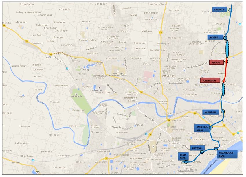
Detailed
 D        Project Repo
                     ort for Rail Based Masss Transit System in Varanasi
                                                                V
Fin
  nal Report                                                                   EXECUTIVE SUMMARY
                                                                                         S

                                                   FIGURE 0.1:STUDY AREA ‐ VARANASI
                                                                           V        DEVELLOPMENT AUTHO
                                                                                                     ORITY AREA

                                                        February, 2016                   Page 0‐2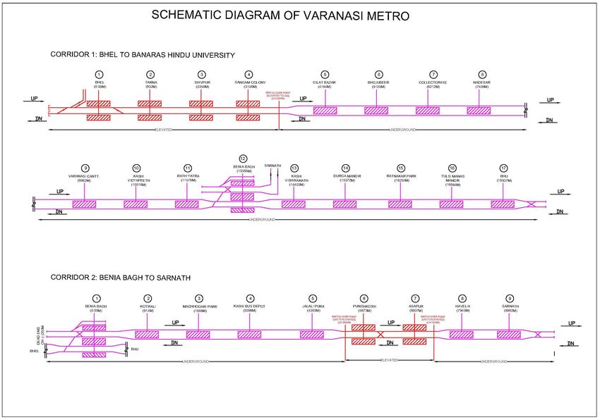
Detailed Project Report for Rail Based Mass Transit System in Varanasi
Final Report                                                                       EXECUTIVE SUMMARY

                                       TABLE 0.1: LANDUSE PARAMETERS

         SN                   Parameters                    2015          2021   2031   2041
         1         Population (Lakh)                         20.6         25.7   31.4    33.6
         2         Employment (Lakh)                         5.8          7.6    9.8     12.0
         3         School Enrolment (Lakh)                   4.9          6.2    7.6     9.0

        A number of traffic & travel surveys were conducted to appreciate and quantify
        the traffic and transport characteristics of commuter travel within the Study
        Area. This data analysis has helped us in accessing existing traffic characteristics
        and developing the Travel Demand Model.

        Comprehensive field surveys and house hold survey were carried out within the
        study area and are listed as under:

              i.       Road Network Inventory Surveys
              ii.      Speed & Delay Surveys
              iii.     Classified Traffic Volume Count Surveys (Mid‐blocks / Screen lines,
                       Intersections & Outer Cordons)
              iv.      Origin‐Destination Surveys at Outer Cordon Locations
              v.       Terminal Passenger (in + out counts) & OD Surveys including Opinion
                       and Willingness to Pay Survey at Bus, Rail Terminals and Airport
              vi.      Bus stops/Auto Stand/IPT Surveys (boarding + alighting + OD) including
                       Opinion and Willingness to Pay Survey
              vii.     Pedestrian Movement Counts
              viii. Parking Surveys
              ix.      Household Interview Surveys
              x.       Work Centre Surveys

        Based on extensive traffic surveys, CMP proposals, Master Plan 2031 and
        extensive consultation with all Stake holders following two priority corridors
        were identified.

        A four stage travel demand model has been developed for transport demand
        forecasting. The daily ridership is shown in the Table 0.2. Total Daily ridership on
        the Phase‐I metro corridors for the years 2021, 2031 and 2041 is expected to be
        5.1 Lakh, 6.7 Lakh and 9.2 Lakh passengers respectively.

                                                       February, 2016                           Page 0‐3
Detailed Project Report for Rail Based Mass Transit System in Varanasi
Final Report EXECUTIVE SUMMARY
TABLE 0.2: RIDERSHIPON PHASE‐I METRO CORRIDORS
Corridor Year Daily Trips (Lakh)
2021 3.2
BHU to BHEL 2031 4.2
2041 5.9
2021 1.9
BeniaBagh to Sarnath 2031 2.5
2041 3.2
The peak hour station boarding and alighting on Phase‐I metro corridors are
presented in Table 0.3.
TABLE 0.3: STATION LOADS ON PHASE‐I METRO CORRIDORS
Peak Hour 2021* Peak Hour 2031* Peak Hour 2041*
Station
Boarding Alighting Boarding Alighting Boarding Alighting
Corridor 1: BHU to BHEL
BHU 5000 4600 8100 5200 12800 12100
TulsiManasMandir 600 1600 800 1700 800 1800
Ratnakar Park 1700 1300 2300 1400 2500 1700
Kali Bari 1100 1100 1600 1700 2200 2500
Kashi Vishwanath 2200 2300 2500 2500 2800 2800
BeniaBagh 11600 12300 15200 16600 17400 17600
Rathyatra Chowk 1800 1700 2100 2000 5000 3200
Kashi Vidyapeeth 9100 6700 10000 11300 14300 11500
Varanasi Junction 9000 8900 12700 10100 13200 13500
Nadesar 1000 2100 1100 2900 1400 3700
Collectorate 1400 2000 3200 2500 3800 4800
Bhojubeer 1400 1200 1900 3000 5100 5300
Gilat Bazar 1600 1600 1900 1900 2100 2200
Sangam Colony 1100 1000 1300 1100 1400 1200
Shivpur 800 800 900 1000 1000 1100
Tarna 1400 1800 1600 2200 1900 2700
BHEL 2100 2100 2600 2600 3300 3300
Corridor 2: BeniaBagh to Sarnath (Akashwani)
Beniabagh 11600 11100 15700 14600 16400 16500
Kotwali 2500 2900 2700 3400 3000 3500
Machodari Park 3200 3300 3500 3600 3900 4000
Kashi Depot 3800 4700 5000 6300 6400 6500
Jalalipura 600 500 700 600 1600 1500
PanchKoshiChauraha 500 500 600 600 800 700
AshapurChauraha 5500 4700 6400 5700 7600 6700
Havelia 900 1200 1100 1500 1400 1900
Sarnath 2300 2100 3400 3100 3900 3600
* Two way boardings/alightings
February, 2016 Page 0‐4Detailed Project Report for Rail Based Mass Transit System in Varanasi
Final Report EXECUTIVE SUMMARY
The peak hour design ridership on Phase‐I metro corridors are presented in
Table 0.4.
TABLE 0.4: DESIGN SECTION LOAD ON PHASE‐I METRO CORRIDORS
Corridor Corridor details Design PHPDT
No. 2021 2031 2041 Design
1 BHU to BHEL 13000 15500 20000 24000
2 Beniabagh to Sarnath 10000 13500 15500 18000
Metro ridership increases gradually and the 2023 ridership is taken same as that
of the year 2021 for the design purpose.
0.3 SYSTEM DESIGN
0.3.1 Permanent way
Gauge
The options available for P‐way Gauge are – Broad Gauge (1676mm), Standard
Gauge (1435mm), Meter Gauge (1000mm). Standard Gauge (1435mm) is being
used worldwide for metro railways with modern state of the art technology.
Standard Gauge permits sharper curves (120m), which is advantageous for
metro alignment in urban scenario. It also results in minimized property
demolition / acquisition. The Land requirement for the maintenance depots,
where a large number of lines are connected together, is also lower in Standard
Gauge.
Standard Gauge rolling stock results in recurring saving in energy consumption
during operation as for the same passenger carrying capacity, gross weight of a
metro coach is lower than for the Broad Gauge.
As the metro rail alignment will pass through built‐up areas / stretches and in
view of the advantages offered by Standard Gauge, it is proposed to adopt
Standard Gauge (1435mm).
Rail Section and Grade
For main lines, 60KG UIC HH rails of grade 1080 are proposed. For other than
main lines and Depot lines, 60 kg rails of grade 880 (without Head hardening) are
proposed. These rails are being manufactured indigenously. The rails for main
lines and depot lines should also conform to the technical specifications laid
down by Indian Railways in IRS‐T‐ 12‐2009.
February, 2016 Page 0‐5Detailed Project Report for Rail Based Mass Transit System in Varanasi
Final Report EXECUTIVE SUMMARY
The rails should have cant of 1 in 20 and wheel profile of rolling stock should be
compatible with rail profile.
Formation
Ballast less track is proposed for elevated and underground stretches. At Depot,
following track structure is proposed to serve specific usage:‐
Ballast less for Washing Line
Steel pedestal for inspection lines
Embedded Rail type inside Workshop
Conventional Ballasted track for Stabling and other line
Fastening System for Ballasted Track
In Feb. 2015, Govt. of India, Ministry of Railways, has issued “Procedure for
Safety certification and Technical clearance of Metro System”. Part‐A, Annexure
C‐2 of the said document covers “Performance criteria of fastening system for
ballastless track on Metro Railways/MRTS System”. Ministry of Railways has
already approved certain fastening systems complying the requisite
performance criteria.
Further, scope for introduction of “new fastening system” has been made
available (for those not approved by Ministry of Railways) with the proviso
thatthe details of such fastening systems shall be made available to Ministry of
Railways (MoR) and the same will be kept under observation by MoR for a
period of two years under service conditions in association with Metro
Railways/MRTS system.
Turnouts and Scissor Crossover
From considerations of maintainability and riding comfort, it is proposed to lay
following two types of turnouts:
On main lines, 1 in 9 type turnout with a lead radius of 300 m and speed
potential on divergent track as 45 km/h.
However, at BeniaBagh station, due to space constraint, 1:7 crossovers
have been proposed with lead radius of 140m and speed potential on
divergent track as 25km/h.
On Depot lines, 1 in 7 type turnout with a lead radius of 140 m and speed
potential on divergent track as 25 km/h.
The Scissors cross‐overs on Main Lines (1 in 9 type) will be with a minimum
February, 2016 Page 0‐6Detailed Project Report for Rail Based Mass Transit System in Varanasi
Final Report EXECUTIVE SUMMARY
track centre of 4.5 m.
Welding
To minimize noise and vibrations, track joints should be welded by Flash Butt
Welding Technique and Alumino‐Thermit Welding may be done only for those
joints which cannot be welded by Flash Butt Welding Technique.
0.3.2 Traction system
Traditionally, electric traction is used in Metro systems for requirement of high
acceleration and pollution‐free services in urban areas. There are three standard
and proven systems of electric traction for use in suburban and metro lines, viz:‐
750V dc third rail, 1500V dc overhead catenary and 25kV ac overhead catenary
system. All the three systems are presently in use in India (750 V dc third rail in
Kolkata & Bangalore Metro, 1500V dc catenary in Mumbai suburban of Central
Railways and 25 kV ac catenary in Delhi, Jaipur, Chennai, Hyderabad Metro &
Indian Railways). 1500 V dc system of Central Railways in Mumbai suburban is
currently being converted to 25 kV ac to meet increase traffic demand.
The 1500V DC third rail system has been adopted in Chinese Metros by
Guangzhou Metro and Shenzhen Metro during last decade. There is not much
experience over use of 1500V DC third rail system and also it has major
constraints on requirement of power block for any kind of attention to track,
signaling and other equipment.
Worldwide about 65% of the Metro rail Systems have 750V DC Third Rail traction
system. The system offers the advantage of aesthetics, reliability and low
maintenance. However, the traffic handling capacity is limited to about 45,000
PHPDT. The traffic demand estimated for the corridors of Varanasi Metro is
about 24000 passengers for BHU to BHEL corridor and 18000 passengers for
Beniabagh to Sarnath corridor.
Considering the ultimate traffic demand and the techno economic advantages
offered by 750V DC system, it is proposed to adopt 750V DC Third Rail system for
Varanasi MRTS.
0.3.3 Rolling stock
Rolling Stock proposed for Varanasi Metro will be similar to Bangalore/ Kochi
Metro. Rolling stock will be suitable for grade of operation GoA3 or higher. The
specifications of the rolling stock and its procurement may be decided on the
basis of the project implementation mechanism. The broad features of Rolling
Stock which may be followed for the present corridor are presented in Table 0.5.
February, 2016 Page 0‐7Detailed Project Report for Rail Based Mass Transit System in Varanasi
Final Report EXECUTIVE SUMMARY
TABLE 0.5: BROAD FEATURES OF ROLLING STOCK
S.N. Parameter Description
Vehicle dimensions
Length (including coupler) 22.6 m
1
Width 2.9 m
Height 3.9 m
2 Train Composition 3 CAR‐ DMC + TC + DMC
3 Coach construction Lightweight stainless steel/Aluminium body
4 Axle load 16 T
5 Propulsion system 3 phase drive system with VVVF control
6 Type of traction supply 750 V DC Third Rail Traction
The carrying capacity of Metro Rail Vehicle is indicated in Table 0.6
TABLE 0.6: CARRYING CAPACITY OF METRO RAIL
Driving Motor Car
Trailer Car (TC) 3 Car Train
(DMC)
Description
Dense Dense Dense
Normal Crush Normal Crush Normal Crush
Crush Crush Crush
Seated 43 43 43 50 50 50 136 136 136
Standing 102 204 272 110 220 293 314 630 839
Total 145 247 315 160 270 343 450 766 975
0.3.4 Ventilation and air‐conditioning system
The underground stations of the corridor are built in a confined space. A large
number of passengers occupy concourse halls and the platforms, especially at
the peak hours. The platform and concourse areas have a limited access from
outside and do not have natural ventilation. It is therefore, essential to provide
forced ventilation in the stations and inside the tunnel.
The large quantity of heat generated in underground stations cannot be
extracted by simple ventilation, especially when the outdoor air temperature
and humidity is high. It is, therefore, essential to provide mechanical cooling in
order to remove the heat to the maximum possible extent. As the passengers
stay in the stations only for short periods, a fair degree of comfort conditions,
just short of discomfort are considered appropriate.
The details of the Ventilation and Air‐conditioning (VAC) system requirements
for the underground section of the proposed corridors include the following:
February, 2016 Page 0‐8Detailed Project Report for Rail Based Mass Transit System in Varanasi
Final Report EXECUTIVE SUMMARY
Station Air‐conditioning System
Ventilation System for station plant rooms (ancillary spaces)
Station Smoke Management System
Tunnel Ventilation System
0.3.5 Signalling system
The signaling system shall provide the means of an efficient train control
ensuring safety in train movement. It assists in optimization of metro
infrastructure investment and running of efficient train services on the network.
The Signaling & Train Control system will ensure –
High level of safety with trains running at close headway ensuring
continuous safe train separation.
Eliminate accidents due to driver passing Signal at Danger by continuous
speed monitoring and automatic application of brake in case of disregard
of signal / warning by the driver.
Provide safety and enforces speed limit on section having permanent and
temporary speed restrictions.
Improve capacity with safer and smoother operations. Driver will have
continuous display of Target Speed / Distance to Go status in his cab
enabling him to optimize the speed potential of the track section. It
provides signal / speed status in the cab even in bad weather.
Moving block feature shall provide enhancement of headway.
Increase productivity of rolling stock by increasing line capacity and train
speeds, and enabling train to arrive at its destination sooner. Hence more
trips will be possible with the same number of rolling stock.
Improve maintenance of Signaling and telecommunication equipments by
monitoring system status of trackside and train born equipments and
enabling preventive maintenance.
The Communication based Train Control (CBTC) Signaling system provides
adequate safety level of CENELEC SIL‐4 (Safety Integrity Level) and permits an
operational headway of 90 seconds with continuous automatic train control. The
CBTC Technology is proven now in many metros around the world and is also
suitable for UTO (Unattended Train Operation) / DTO (Driverless Train
Operation). Considering the above, CBTC system is recommended to be adopted
for Varanasi Metro corridors.
February, 2016 Page 0‐9Detailed Project Report for Rail Based Mass Transit System in Varanasi
Final Report EXECUTIVE SUMMARY
0.3.6 Telecommunication
The telecommunication system acts as the communication backbone for
Signaling and other systems and provides telecommunication services to meet
operational and administrative requirements of metro network shall be based
on Giga Ethernet based IP network system.
The state of the art latest technology being used in different metros worldwide,
is proposed to be provided for the Varanasi MRTS.
0.3.7 Fare collection system
Mass Rapid Transit Systems handle large number of passengers. Ticket issue and
fare collection play a vital role in the efficient and proper operation of the
system. To achieve this objective, ticketing system shall be simple, easy to
use/operate, easy on accounting facilities, capable of issuing single/multiple
journey tickets, amenable for quick fare changes and require overall lesser
manpower. Automatic fare collection system meets these requirements.
The AFC system shall have functionality of interface to CCHS (Central Clearing
House System) facility with provision of integration with other transit (metro,
bus etc) and non‐transit (parking, toll etc) which may be planned in future in line
with the state / national policy. In addition, the proposed AFC system shall also
be NFC (Near Field Communication) enabled so that customers can use their NFC
enabled Mobile phones for metro travel. Facility of recharging of Travel Cards
using Cash, Debit/Credit Cards and Netbanking/web portal shall also be
available. AFC system shall also support offsite sales terminals also, wherein
cards and tokens can be dispensed at locations outside metro premises.
Keeping in view Metro Railways Automatic Fare Collection System and the fact
that Contactless card/ token technology proves to be cheaper than magnetic
technology in life cycle cost due to reduced maintenance, it is proposed to
provide computer based automatic fare collection system with Contactless
smart token/card type ticketing.
0.3.8 Platform screen doors (PSD)
Platform Screen Doors (PSD) are proposed to be provided at stations to screen
the passengers on the platform from the track. These glass doors shall be
powered for automatic operation and located along the platform at the platform
edge throughout the passenger area. The door locations will be corresponding to
the train car passenger door locations. Opening/ closing of the PSD will be after
receipt of the DOORS OPEN/ DOORS CLOSE command signals from the Signalling
Link. Signalling link enables automatic operation of PSD only when the train
February, 2016 Page 0‐10Detailed Project Report for Rail Based Mass Transit System in Varanasi
Final Report EXECUTIVE SUMMARY
stops within ±300mm limits.
Considering the fact that half height PSD are cheaper to install than full height
platform screen doors requiring more metallic framework for support, it is
recommended to provide half height Platform Screen Doors at all the stations.
0.4 CIVIL ENGINEERING
0.4.1 Geometric design parameters
TABLE 0.7: DESIGN PARAMETERS
SN CRITERIA DIMENSION
1 Gauge 1435 mm
2 Design Speed 90 Kmph
3 Maximum Axle Load 16T
4 Electric Power Collection 750V DC, THIRD RAIL
TABLE 0.8: HORIZONTAL CURVE PARAMETERS
Description U/G Section Elevated Section
Desirable Minimum Radius 300 m 200 m
Absolute minimum Radius 200 m 120 m
Minimum curve radius at stations 1000 m
Maximum permissible cant (Ca) 110 mm*
Maximum cant deficiency (Cd) 85 mm
* The applied cant will be decided in relation to normal operating speeds at specific locations
like stations/vicinity to stations.
TABLE 0.9: TRACK CENTRE AND HEIGHT IN ELEVATED SECTION
Minimum Track Minimum Rail Level above
Parameter
Centre Ground Level
Mid‐Section 4.00 m* 7.50 m**
Station w/o Scissor Cross‐over 4.00 m 12.00 m
Station with Scissor Cross‐over 4.50 m 12.00 m
Note:
*Track centre in elevated section can be modified as per the choice of
girder/superstructure. For Double U‐girder minimum 4.60 m track centre will be
provided.
**For I‐girder and Box‐girder, Minimum Rail Level above Ground Level shall be 8.50 m
February, 2016 Page 0‐11Detailed Project Report for Rail Based Mass Transit System in Varanasi
Final Report EXECUTIVE SUMMARY
TABLE 0.10: TRACK CENTRE AND DEPTH IN UNDERGROUND SECTION
Minimum Track
Description Depth below Ground Level
Centre
Running section by TBM
15.00 m 20.0 m
Running section by cut & cover except
4.60 m 12.60 m
ramp
Stations by cut & cover and 13m island
16.03 m 20.0 m
PF
Stations by cut & cover and side
4.60 m 20.0 m
platform
Stations by NATM
22.00 m 20.0 m
TABLE 0.11: GRADIENT PARAMETERS
Description Desirable Absolute Minimum
Gradient at Mid‐Section Upto2% Upto 4% (compensated)
Gradient at Stations Level Upto 0.25%
TABLE 0.12: VERTICAL CURVE PARAMETERS
Parameter Vertical Curve
Desirable Radius on Main line 2500 m
Absolute Minimum Radius on Main line 1500 m
Minimum Length of Vertical Curve 20 m
0.4.2 Engineering Survey
Topographic Surveys
i) Establishment of Horizontal Control Points using DGPS
ii) Densification of Horizontal Control Points using Total station
iii) Establishment of Vertical Control Points
iv) Detailed survey of corridor
v) Preparation of drawings.
vi) Site verification of features and finalization of drawings.
vii) Alignment design on basis of verified drawings
0.4.3 Geotechnical investigations
General Geology & Related Characteristics
The general geological sequence of Varanasi region can be classified on the basis
of lithology, the Quaternary sediments of the Gangetic plain have been broadly
classified into Older Alluvium (Banda Alluvium and Varanasi Alluvium) and
Newer Alluvium. The Banda Alluvium, which has provenance in
February, 2016 Page 0‐12Detailed Project Report for Rail Based Mass Transit System in Varanasi
Final Report EXECUTIVE SUMMARY
peninsular/cratonicregion rests over the Precambrian rocks. The sediments of
Varanasi Alluvium of (Middle to Late Pleistocene age) derived from the
Himalayan provenance overlie Banda Alluvium. The Newer Alluvium represents
the youngest sequence. Generally, this sequence is confined within the flood
plain limits of present day rivers. The area under study belongs to the central
part of the Gangetic Alluvial Plain.
The main drainage is provided by southeasterly flowing Ganga river whose
braided course in the area has a maximum width of 5 km near Fatehgarh. The
major tributaries flowing through the northern gangetic plain include Ramganga
and Garra, having their confluence with Ganga at Bhojpur (1.5 km. d/s of
Fatehgarh) and Kannauj, respectively. The generalized geological succession is
shown in Table 0.13.
TABLE 0.13: GEOLOGICAL SUCCESSION IN VARANASI
UNIT LITHOLOGY
NEWER ALLUVIUM
Ganga, Ramganga, Garra, Kali
Light grey, fine to medium‐grained sand,
recent
laminated clay and minor silt.
Alluvium
Ganga. Ramganga, Garra
Fine to medium‐grained grey micaceous sand
terrace
with thin layers of silt and clay.
Alluvium.
Disconformity
Polycyclic sequence of clay and silt with
Silt‐clayey facies
concrete and ferruginous concretions.
Sandy facies Oxidised brownish micaceous sand and silt.
Geotechnical Investigations
In total, 30 BHs have been drilled of 30 m depth each, all along the length of
proposed Metro alignment. 20BHs have been drilled in Corridor‐I (BHEL to BHU),
9 BHs have been drilled in Corridor‐II (Sarnath to Kotwali) & 1 BHs have been
drilled for depots.
Considering field and lab test results, pile foundations have been recommended for
the proposed viaduct at locations of BH‐1 to BH‐4, BH‐21to BH‐24, & BHD‐1.Shallow
foundation is also recommended at location of BH‐D‐1 for light weight structures.
Portion between BH‐5 to BH‐20 & BH‐25 to Bh‐29 is proposed as underground section.
February, 2016 Page 0‐13Detailed Project Report for Rail Based Mass Transit System in Varanasi
Final Report EXECUTIVE SUMMARY
The load capacities of piles are based on empirical correlation’s and should be
confirmed by conducting pile load test as per IS: 2911 (Part 4) on test piles before
execution of working piles.
Since the proposed site is situated in seismic Zone III of the seismic zonation map of
India, suitable seismic coefficient commensurate to seismic Zone III(IS: 1893) should
be adopted in the design of the structures.
Wherever Undisturbed samples (UDS) could not be obtained due to stiff soil (SPT
value more than 30), cohesion & angle of internal friction values have been obtained
from observed SPT N value.
0.4.4 Route alignment
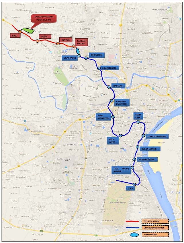
Corridor‐1: BHEL to Banaras Hindu University
Considering centre line of BHEL station as 0.00m, this corridor is 19350m long starting
from ‐325m and running upto 19025m. This corridor consists of elevated and
Underground stretches along with Switch over Ramps (SOR). The corridor is
summarized in Table 0.14.
TABLE 0.14: SUMMARY OF SECTIONS OF CORRIDOR 1
Alignment Type From(m) To(m) Length(m)
Elevated ‐325 3321 3646
Ramp (+)7.5m to (‐)8.0m 3321 3755 434
Underground 3755 19025 15270
Total 19350
The proposed alignment of Corridor‐1 starts near BHEL along NH‐56. The
alignment starts along NH‐56 as elevated and heads in East direction.
Total length of the section is about 3.65 Km. Figure 0.2 shows the proposed
corridor.
Depot for both the corridors is proposed in Ganeshpur Land near BHEL.
Total area required for the depot is 13.2 Hac.
Total length of the corridor is 19.35 Km and is elevated for a length of 3.856
Km, underground for 15.494 Km and 0.12 Km for depot entry/exit.
17 stations have been proposed consisting of 4 elevated stations and 13
underground stations.
Summary of Special spans & Portals may be referred in Chapter 4 of this
DPR.
February, 2016 Page 0‐14Detailed Project Report for Rail Based Mass Transit System in Varanasi
Final Report EXECUTIVE SUMMARY
Switch Over Ramp
Ramp is required to provide transition from Elevated to underground alignment
after Sangam Colony station. Horizontal and vertical alignment in this stretch has
been designed in such fashion so that minimum land is required.
The ramp (7.5m to (‐) 8.0m) has been proposed at limiting gradient of 4%
(compensated) from Ch: 3310 m to Ch: 3744 m to become underground. About
4340sqm land for locating the ramp will be required permanently in State
Government road.
MORT&H is planning for road widening of NH‐56 from Babatpur to GIlat Bazar.
The planning is in initial stage and drawings are not developed. Consequently,
MORT&H is informed the planning of MRTS corridor in the section from BHEL to
Gilat Bazar.
TABLE 0.15: ABSTRACT OF HORIZONTAL CURVES – CORRIDOR 1
No. of
S. No. Curve Radius Length Percentage
Occurrences
1 ≤190 0 0.00 0.00
2 >190 500 ≤ 800 3 1472 12.47
5 >800 ≤ 1000 2 275 2.33
6 >1000 1 120 1.02
Total 36 11800 100.00
TABLE 0.16: ABSTRACT OF GRADIENTS – CORRIDOR 1
Nos. of Length %
S. No. Description
Occurrences (m) Length
1 Level (0%) 17 6585 34.03
2 >0% to 1% 14 8674 44.82
3 >1% to 2% 11 2751 14.22
4 >2% to 3% 3 626 3.23
5 >3% 1 715 3.69
TOTAL 46 19350 100.00
Corridor‐2: Benia Bagh to Sarnath
Considering centre line of Benia Bagh station as 0.00m, this corridor is 9885 m long
starting from (‐)245m and running upto 9395m and including 245m stabling lines at
Beniabagh. This corridor starts with first station at BeniaBagh.
February, 2016 Page 0‐15Detailed Project Report for Rail Based Mass Transit System in Varanasi
Final Report EXECUTIVE SUMMARY
Track interchange between corridor‐I & II is planned at this station. The corridor runs
underground from Benia Bagh upto Jalalipura. Further, it ramps up on North side of
Varuna river with two elevated station at Punchkoshi and Asapur. The corridor further
ramps down after crossing proposed flyover at Asapur road crossing. The corridor then
runs underground from Havelia and terminates at Sarnath in Post Office land.
The corridor is summarised in Table 0.17
TABLE 0.17: SUMMARY OF SECTIONS: CORRIDOR‐2
Chainage (m) Length
Description
From To (m)
Underground ‐245 5300 5545
UG Stablings ‐ ‐ 245
Ramp 5300 5687 387
Elevated 5687 7235 1548
Ramp 7235 7625 390
Underground 7625 9395 1770
Total 9885
TABLE 0.18: ABSTRACT OF HORIZONTAL CURVES – CORRIDOR 2
No. of
S. No. Curve Radius Length Percentage
Occurrences
1 ≤190 0 0.00 0.00
2 >190 500 ≤ 800 1 119 2.13
5 >800 ≤ 1000 2 454 8.14
6 >1000 2 215 3.86
Total 21 5570 100.00
TABLE 0.19: ABSTRACT OF GRADIENTS – CORRIDOR 2
No.s of
Percentage
S. No. Description Occurrences Length (m)
1 Level (0%) 11 3225 33.46
2 >0% to 1% 5 2754 28.57
3 >1% to 2% 2 393 4.08
4 >2% to 3% 6 1049 10.88
5 >3% 3 2218 23.01
TOTAL 27 9639 100.00
February, 2016 Page 0‐16Detailed Project Report for Rail Based Mass Transit System in Varanasi
Final Report EXECUTIVE SUMMARY
FIGURE 0.2: PROPOSED METRO CORRIDOR‐1
February, 2016 Page 0‐17Detailed Project Report for Rail Based Mass Transit System in Varanasi
Final Report EXECUTIVE SUMMARY
FIGURE 0.3: PROPOSED METRO CORRIDOR‐2
February, 2016 Page 0‐18Detailed Project Report for Rail Based Mass Transit System in Varanasi
Final Report EXECUTIVE SUMMARY
0.4.5 ASI Monuments along Metro Corridors
TABLE 0.20: LIST OF ANCIENT MONUMENTS ALONG METRO CORRIDORS
Distance
Prohibited
from Within Within
S. Name of Nearest Distance as
Monument's Prohibited Regulated
No. Monuments Station per ASI
boundary Area (Y/N) Area (Y/N)
(m)
wall (m)
Corridor‐1: BHEL to BHU
Victoria
1 BeniaBagh 100 10 Y Y
Memorial
Kashi
Man Mandir Vishwanath
2 100 64 Y Y
Observatory (Chitranjan
park)
Grave of
Ratnakar
3 European 100 100 N Y
Park
Officers
Corridor‐2: BeniaBagh to Sarnath
Chaukhandi
1 Havelia 215 220 N Y
Stupa
2 Sarnath Sarnath 172 218 N Y
0.4.6 Utility Diversion
For identification of likely utilities in the proposed metro corridor ‐1 and Corridor ‐2, liaison
was made with Organizations/Departments as mentioned in Table 0.21.
TABLE 0.21: UTILITY RESPONSIBILITY DEPARTMENTS
S. No. ORGANIZATION/ DEPARTMENT UTILITY SERVICES
Road Construction and maintenance of
1 MORT&H
State highways, Municipal Roads etc.
2 PWD City Roads
Indian Railways Railway crossings, subways, signals, railway
3
bridges etc.
4 VMC‐Jal Nigam Water pipe lines.
5 Jal KalVibhag Sewer lines and Water lines
6 Torrent Power HT/other overhead Power lines.
7 VMC‐Sewerage Sewerage pipe lines.
8 VMC‐Storm Water Drains Storm water drainage.
9 Irrigation Department Canal
10 Gas Authority of India (GAIL) Gas Pipelines
11 Green Gas Limited Gas Pipelines
Telecommunications cables, junction
12 BSNL (OFC)
boxes, telephone posts, O.H lines.
February, 2016 Page 0‐19Detailed Project Report for Rail Based Mass Transit System in Varanasi
Final Report EXECUTIVE SUMMARY
S. No. ORGANIZATION/ DEPARTMENT UTILITY SERVICES
Telecommunications cables, junction
13 BSNL (Cables)
boxes, telephone posts, O.H. Lines.
Telecommunications cables, junction
14 Airtel (Cables)
boxes, telephone posts, O.H. Lines.
Telecommunications cables, junction
15 Idea (Cables)
boxes, telephone posts, O.H. Lines.
Telecommunications cables, junction
16 Tata Tele Services (Cables)
boxes, telephone posts, O.H. Lines.
Telecommunications cables, junction
17 Vodafone (Cables)
boxes, telephone posts, O.H. Lines.
North Telecom Region (Long Telecommunications cables, junction
18
Distance Cables) boxes, telephone posts, O.H. Lines.
0.4.7 Stations
List of stations along with their chainage and interstation distances (ISD) for Corridor‐1 and
Corridor‐2 are given in Table 0.22 and 0.23 respectively. Wherever space and site condition
permits, portal type arrangement is proposed for elevated stations. However, due to limited
ROW and narrow roads, most of the elevated stations are proposed with Cantilever type
arrangement, which is also used extensively in Jaipur Metro and for specific stations in LMRC
as well as DMRC.
Schematic diagram for Varanasi Metro corridors is shown in Figure 0.4.
February, 2016 Page 0‐20Detailed Project Report for Rail Based Mass Transit System in Varanasi
Final Report EXECUTIVE SUMMARY
TABLE 0.22: LIST OF STATIONS FOR CORRIDOR‐1
S. Tentative Inter Station Station Height/ Underground/ Construction Proposed Proposed
Station Name
No. Chainage (m) Distance Depth Elevated Methodology Length Width
1 BHEL 0.00 ‐‐ 13 Elevated Cantilever 85 19.2
2 Tarna 932 932 13 Elevated Cantilever 75 19.2
3 Shivpur 2259 1327 13 Elevated Cantilever 85 19.2
4 Sangam Colony 3106 847 13 Elevated Cantilever 75 19.2
5 Gilat Bazar 4184 1078 ‐15 Underground Cut & Cover 160 26.55
6 Bhojubeer 5125 941 ‐20 Underground Cut & Cover 160 22.45
7 Collectorate 6212 1087 ‐20 Underground Cut & Cover 140 26.55
8 Nadesar 7408 1196 ‐20 Underground Cut & Cover 130 26.55
9 Varanasi Cantt. 8862 1454 ‐20 Underground Cut & Cover 140 26.55
10 Kashi Vidyapeeth 10018 1156 ‐20 Underground Cut & Cover 130 26.55
11 RathYatra 11576 1558 ‐20 Underground Cut & Cover 140 26.55
12 BeniaBagh 13365 1789 ‐20 Underground Cut & Cover 140 47
13 Kashi Vishwanath 14403 1038 ‐20 Underground Cut & Cover 130 26.55
14 DurgaMandir 15372 969 ‐20 Underground Cut & Cover 97 26.55
15 Ratnakar Park 16030 658 ‐20 Underground Cut & Cover 97 26.55
16 TulsiManasMandir 16884 854 ‐20 Underground Cut & Cover 160 22.45
17 BHU 18507 1623 ‐20 Underground Cut & Cover 160 22.45
February, 2016 Page 0‐21Detailed Project Report for Rail Based Mass Transit System in Varanasi
Final Report EXECUTIVE SUMMARY
TABLE 0.23: LIST OF STATIONS FOR CORRIDOR‐2
Station Proposed Proposed
Tentative Inter Station Underground/ Construction
S. No. Station Name Height/ Depth Length Width
Chainage (Km) Distance (Km) Elevated Methodology
(m) (m) (m)
1 BeniaBagh 0.00 ‐20 Underground Cut & Cover 140 47
2 Kotwali 914 914 ‐20 Underground Cut & Cover 130 26.55
3 Machhodari Park 1688 774 ‐20 Underground Cut & Cover 140 26.55
4 Kashi Bus Depot 3099 1411 ‐20 Underground Cut & Cover 97 26.55
5 Jalalipura 4363 1264 ‐15 Underground Cut & Cover 140 26.55
6 PunchkoshiChauraha 5873 1510 13 Elevated Cantilever 75 19.2
7 AsapurChauraha 6807 934 18 Elevated Cantilever 85 19.2
8 Havelia 7943 1136 ‐15 Underground Cut & Cover 160 26.55
9 Sarnath 8982 1039 ‐20 Underground Cut & Cover 140 26.55
February, 2016 Page 0‐22Detailed Project Report for Rail Based Mass Transit System in Varanasi
Final Report EXECUTIVE SUMMARY
FIGURE 0.4: SCHEMATIC DIAGRAM OF VARANASI METRO
February, 2016 Page 0‐23Detailed Project Report for Rail Based Mass Transit System in Varanasi
Final Report EXECUTIVE SUMMARY
0.4.8 Land Requirement
Land will be required for the following main components:
MRTS Structure (including Route Alignment), StationBuilding, Platforms, Entry/Exit
Structures, Traffic Integration Facilities, Depots, etc.
Receiving/Traction Sub‐stations
RadioTowers
Temporary Construction Depots and work sites.
Abstract of land requirements for different components of corridors are given in Tables 0.24
and 0.25.
TABLE 0.24: LAND & STRUCTURES REQUIREMENT: CORRIDOR‐I
(IN SQM)
Permanent Temporary Structures
Ownership Purpose
Land Land (Floor area)
Central Govt
Alignment, Station etc 0.07 0.40 0.05
(Northern Railway)
State Govt
Alignment, Station etc 1 2.6 0.2633
Alignment, Station etc 1.05 2.5 0.52
13.2 0.5
Depot (Ganeshpur) 0
Private Casting Yard 0 6 0
RSS 0.3 0 0
Total 14.55 8.5 1.02
TABLE 0.25: LAND & STRUCTURES REQUIREMENT: CORRIDOR‐II
(IN SQM)
Permanent Temporary Structures
Ownership Purpose
Land Land (Floor area)
Central Govt Alignment, Station etc 0.14 0 0.0242
Alignment, Station etc 0.8 2.1 0.105
State Govt RSS 0.3 0 0
Total 1.1 2.1 0.105
Alignment, Station etc 0.13 0 0.18
Private Casting yard 0 4 0
Total 0.13 4 0.18
February, 2016 Page 0‐24Detailed Project Report for Rail Based Mass Transit System in Varanasi
Final Report EXECUTIVE SUMMARY
0.5 STATION PLANNING AND INTERMODAL INTEGRATION
0.5.1 Station planning
The stations have been planned based on the basis of following parameters:
a. Station planning is dependent on the peak hour traffic load for each station.
In the design year, maximum PHPDT of 24000 passengers for ‘BHU to BHEL
and 18000 passengers for ‘Benia Bagh to Sarnath’ is expected.
b. The platform length is planned for 3 cars train.
c. The total evacuation time for the movement of all passengers in an
emergency from platform level to the landing at the next level does not
exceed 4.0 minutes (as per “NFPA 130 Guidelines”) in underground stations.
However this is 5.5 minutes in elevated stations considering that the stations
are open and the risk is much less.
d. The station planning is in compliance to the “Guidelines and space Standards
for Barrier Free Built Environment for Disabled and Elderly persons”
published by the Ministry of Urban Affairs and Employment India in 1998.
e. Seven typical designs have been suggested for various station types and
these will form basis for planning of all the stations (Table 0.26).
Type Station Type Size (sq m) Levels Construction Type
A Underground 160 X 22.45 3 Cut and Cover
B Underground 160 X 26.55 2 Cut and Cover
C Underground 130 X 26.55 3 Cut and Cover
D Underground 97 X 26.55 4 Cut and Cover
E Interchange 140 X 47 3 Cut and Cover
F Elevated 75 X 19.20 2 Cantilever
G Elevated 75 X 21.70 2 Cantilever
TABLE 0.26: STATION TYPOLOGY
S. Station
No. Name of Station Description Type Size (sq m) Levels TSS Entry/Exits
Corridor 1 BHU to BHEL
Yes 2 exits of 3.2 m wide stairs
1 BHU Underground A 160 X 22.45 3
(S) with 4 escalators
2 exits of 2.4 m wide stairs
2 TulsiManasMandir Underground A 160 X 22.45 3 No
with 1 escalator
Yes 2 exits of 2.4 m wide stairs
3 Ratnakar Park Underground D 97 X 26.55 4
(S) with 4 escalators
February, 2016 Page 0‐25Detailed Project Report for Rail Based Mass Transit System in Varanasi
Final Report EXECUTIVE SUMMARY
S. Station
No. Name of Station Description Type Size (sq m) Levels TSS Entry/Exits
2 exits of 2.4 m wide stairs
4 DurgaMandir Underground D 97 X 26.55 4 No
with 1 escalator
Yes 2 exits of 2.4 m wide stairs
5 KashiVishwanath Underground C 130 X 26.55 3
(S) with 4 escalators
2 exits of 4.2 m wide stairs
6 BeniaBagh Interchange E 140 X 47 2 No with 6 escalators (4 nos. up +
2 down)
Yes 2 exits of 2.4 m wide stairs
7 RathYatra Underground C 140 X 26.55 3
(L) with 2 escalators (both up)
3 exits of 3 m wide stairs
8 Kashi Vidyapeeth Underground C 130 X 26.55 3 No
with 3 escalators
Yes 3 exits of 3 m wide stairs
9 Varanasi Cantt. Underground C 140 X 26.55 2
(L) with 3 escalators
2 exits of 2.4 m wide stairs
10 Nadesar Underground C 130 X 26.55 3 No
with 1 escalator
Yes 2 exits of 2.4 m wide stairs
11 Collectorate Underground C 140 X 26.55 3
(L) with 1 escalator
2 exits of 2.4 m wide stairs
12 Bhojubeer Underground A 160 X 22.45 3 No
with 2 escalators (both up)
Yes 2 exits of 2.4 m wide stairs
13 Gilat Bazar Underground B 160 X 26.55 2
(S) with 1 escalator
2 exits of 2.4 m wide stairs
14 Sangam Colony Elevated F 75 X 19.2 2 No
with 2 escalator
Yes 2 exits of 2.4 m wide stairs
15 Shivpur Elevated F 85 X 19.2 2
(L) with 2 escalator
2 exits of 2.4 m wide stairs
16 Tarna Elevated F 75 X 19.2 2 No
with 2 escalator
Yes 2 exits of 2.4 m wide stairs
17 BHEL Elevated F 85 X 19.2 2
(L) with 2 escalator
Corridor 2 BeniaBagh to Sarnath
2 exits of 4.7 m wide stairs
Yes
1 BeniaBagh Interchange E 140 X 47 2 with 6 escalators (4 nos. up +
(L)
2 down)
2 exits of 2.4 m wide stairs
2 Kotwali Underground C 130 X 26.55 3 No
with 2 escalators (both up)
Yes 2 exits of 2.4 m wide stairs
3 Machodari Park Underground C 140 X 26.55 3
(L) with 2 escalators (both up)
2 exits of 3 m wide stairs
4 Kashi Bus Depot Underground D 97 X 26.55 4 No
with 2 escalators (both up)
Yes 2 exits of 2.4 m wide stairs
5 Jalalipura Underground C 140 X 26.55 3
(L) with 1 escalator
2 exits of 2.4 m wide stairs
6 PanchKoshiChouraha Elevated F 75 X 19.2 2 No
with 2 escalator
Yes 2 exits of 2.4 m wide stairs
7 AsapurChouraha Elevated G 85 X 21.7 2
(L) with 2 escalators
February, 2016 Page 0‐26Detailed Project Report for Rail Based Mass Transit System in Varanasi
Final Report EXECUTIVE SUMMARY
S. Station
No. Name of Station Description Type Size (sq m) Levels TSS Entry/Exits
2 exits of 2.4 m wide stairs
8 Havelia Underground B 160 X 26.55 2 No
with 2 escalators (both up)
Yes 2 exits of 2.4 m wide stairs
9 Sarnath Underground C 140 X 26.55 3
(L) with 2 escalators (both up)
0.5.2 Parking at stations
Parking provision for commuters is one of the key factors determining success of the
metro system. Parking provisions along with priority to pedestrians through Foot Over
Bridges and Bus feeder services will encourage more commuters to use the metro
system who could safely park their vehicles at the nearest station, walk to the station
or rely on feeder connectivity. A total of 1,73,355 Sqm area of land has been
considered for parking and property development. A total of 19,202 Sqm of area with
14,162 Sqm along Corridor‐1 and 5,040 Sqm along Corridor‐2 is proposed exclusively
for parking near metro stations.
0.5.3 Transit oriented / property development
Some land parcels along both the metro corridors have been identified after joint site
visits with VDA for parking and property development. Property development shall be
taken up on the upper floors, depending upon the FAR (upto 4) and permitted ground
coverage of 50%. A total of 4.97 lakh Sqm of property development having Residential,
Institutional and Commercial facilities for metro commuters has been proposed to
make the project financially viable. The summary of property development is
presented in Table 0.27.
TABLE 0.27: PROPOSED PARKING &PROPERTY DEVELOPMENT
Area in Sqm.
Property Total Property
SN Metro Station Parking
Development Plot Development Floor
Area
Area Area Space (with FAR of 4)
Corridor‐1:
1 TulsiManasMandir 800 3400 4200 13600
2 Ratnakar Park 900 900
3 BeniaBagh 1221 1221
4 Kashi Vidyapeeth 1200 1200
5 Varanasi Cantt 7241 7241
6 Bhojubeer 800 800
7 BHEL 2000 2000
8 Depot at Ganeshpur* 120000 120000 360000
Corridor‐2:
8 Kotwali 1500 5700 7200 22800
February, 2016 Page 0‐27Detailed Project Report for Rail Based Mass Transit System in Varanasi
Final Report EXECUTIVE SUMMARY
Area in Sqm.
Property Total Property
SN Metro Station Parking
Development Plot Development Floor
Area
Area Area Space (with FAR of 4)
9 Machodari Park 1100 7900 9000 31600
10 Kashi Bus Depot 1240 4353 5593 17412
11 Jalalipura 12800 12800 51200
12 Sarnath 1200 1200
Total 19202 154153 173355 496612
0.5.4 Feeder services
The planning of seamless transport integration facilities at the influence zones of
various metro stations is of utmost importance. As all commuters will not be living
within walking distance of the proposed network, proper planning for feeder services
has been proposed along the metro system.
The feeder buses shall be of high quality, ultra‐modern and customer oriented that
can deliver fast, comfortable and cost‐effective urban mobility. Easy‐to‐board (low
floor), attractive and environmentally friendly buses with air conditioning having
capacity of 35 (Mini‐buses) are proposed for feeder system.
The total number of buses required in the year 2021 is 74 buses, 47 for Corridor‐1 and
27 for Corridor‐2 respectively.
Public bicycle sharing will be provided for the passengers within 1 km to 2 km from the
metro stations influence area. A bicycle sharing system is the service in
which bicycles are made available for free and shared use to metro passengers on a
short term basis.
0.5.5 Intermodal integration and dispersal facilities
The proposals have been formulated for facilitating traffic dispersal and circulation
facilities based on the following considerations:
Minimizing pedestrian/vehicle conflicts and effective passenger interchange with
feeder modes. Proper design of circulation area adjoining the station building to
ensure rapid/ efficient dispersal of the passengers and avoiding conflicts
between pedestrian and vehicular traffic.
Pedestrians require a convenient and safe access to the proposed metro station.
For smooth movement of pedestrians, all the footpaths in the metro station
influence zone will be considered to be upgraded to desired level of comfort and
also proposed new within the stations vicinity areas.
February, 2016 Page 0‐28Detailed Project Report for Rail Based Mass Transit System in Varanasi
Final Report EXECUTIVE SUMMARY
High quality pedestrian access will be accomplished through design factors such
as directness and connectivity, ease of movement, safety and security. The
vendors if any on the footpaths shall be removed and desired accessibility to
metro stations will be provided. The facilities (footpaths/ walkways) will be
directly integrated with the system.
Facilitating passenger interchange with other transit systems: Dedicated linkages
will be proposed like subways, skywalks, covered walkways etc. which will reduce
the passenger travel time and pedestrian load on the roads.
Circulation area with adequate parking space, designated space for embarking
and disembarking for vehicular traffic (pick‐drop zones) and feeder modes like
Buses, IPTs and NMT.
Availability of total carriageway and footpath widths required to cater to the
proposed traffic volumes to be augmented through strengthening of road
shoulder areas and relocation of vendors/hawkers, on‐street parking and all
encroachments from the service/ access roads.
0.5.6 Traffic management plan
The existing traffic loads on roads are projected along the proposed metro corridors
and it is seen that the existing ROW along the corridors itself would take the load of
traffic provided that the ROW is judiciously used. Only limited traffic diversions may be
required.
0.6 DISASTER MANAGEMENT MEASURES
An effective system needs to be in placeunder the provision of ‘Disaster Management
Act, 2005’. Provisions at metro stations include Fire Detection and Suppression
System, Environmental Control System (ECS), Tunnel Ventilation System, Track‐way
Exhaust System (TES), Power Supply System, DG Sets & UPS, Water Supply and
Drainage System, Lights and other facilities which may be deemed necessary. In order
to be prepared for any disaster, it is essential to train the concerned staff in situations
such as fire, rescue of disabled trains, evacuation, etc. and mock drills need to be
conducted.
February, 2016 Page 0‐29Detailed Project Report for Rail Based Mass Transit System in Varanasi
Final Report EXECUTIVE SUMMARY
0.7 DISABLED FRIENDLY FEATURES
The metro system should be user‐friendly ensuring accessibility to persons with
disabilities, people travelling with small children or are carrying luggage, as well as
people with temporary mobility problems and the elderly persons.The standards are
extracted from ‘Indian Roads Congress Code, 103:2012’, ‘Guidelines for Pedestrian
Facilities, Model Building Bye Laws‐2011’ and ‘National Building Code‐2005’, ‘Space
Standards for Barrier Free Built Environment for Disabled and Elderly Persons‐1998
and 2013’and other international best practices / standards. Standarddisabled friendly
facilities within station areas will be providedfor seamless movement around metro
stations.
0.8 SECURITY MEASURES
Security system for metro system plays an important role in helping the system to
become the preferred mode choice for commuters. The three phases of security
system followed include Prevention, Preparedness and Recovery. Various provisions
like CCTV cameras, baggage scanners, metal detectors, bomb detection equipment,
wireless sets, snuffer dogs and related facilities will be part of station security system.
0.9 TRAIN OPERATION PLAN
The train operation plan for the proposed corridors will be based on the following
salient features:
Running of services for 16 hours of a day (6:00 hrs to 22:00 hrs) with a
station dwell time of 20 – 30 seconds.
Scheduled speed for corridor 1 and corridor 2 shall be 35 kmph and 34 kmph.
Make up time of 5‐10% with 10‐15% coasting.
Adequate services to ensure comfortable journey for commuters even during
peak periods.
Based on the Traffic demand, train operation plan and requirement of coaches for
BHU to BHEL corridor and Beniabagh to Sarnath corridor for different horizon years is
given in Table 0.28 and Table 0.29.
TABLE 0.28: TRAIN OPERATION PLAN: BHU – BHEL CORRIDOR
Year 2023 2031 2041 2051
Trains Per Hour 13 16 21 25
Cars per train 3 3 3 3
Avg. Head way (in 276 228 174 144
February, 2016 Page 0‐30Detailed Project Report for Rail Based Mass Transit System in Varanasi
Final Report EXECUTIVE SUMMARY
Year 2023 2031 2041 2051
Seconds)
PHPDT Demand 13000 15500 20000 24000
Capacity 6p/m2 9958 12256 16086 19150
Available 8p/m2 12675 15600 20475 24375
Rake Requirement 21 24 32 38
Total Coach
63 72 96 114
Requirement
TABLE 0.29: TRAIN OPERATION PLAN: BENIABAGH – SARNATH CORRIDOR
Year 2023 2031 2041 2051
Trains Per Hour 10 14 16 19
Cars per train 3 3 3 3
Avg. Head way (in
360 258 228 192
Seconds)
PHPDT Demand 10000 13500 15500 18000
Capacity 6p/m2 7660 10724 12256 14554
Available 8p/m2 9750 13650 15600 18525
Rake Requirement 10 13 15 18
Total Coach
30 39 45 54
Requirement
0.10 MAINTENANCE DEPOT
The Metro corridors will require depot cum maintenance facilities for the
maintenance of 56 rakes of 3 car (38 rakes for corridor 1 and 18 rakes for corridor 2).
Since, track connectivity between the two corridors is proposed at Beniabagh, one
depot near BHEL / Ganeshpur is planned to cater to the maintenance requirements.
The depots will have infrastructure with necessary facilities viz stabling lines,
scheduled inspection lines, workshop for overhaul, unscheduled maintenance
including major repairs, wheel profiling, heavy interior/under frame/roof cleaning etc.
for the rolling stock operational on the corridors as well as maintenance facilities for
Civil – track, buildings, water supply; Electrical – traction, E&M; Signalling &
Telecomm. Automatic Fare Collection etc.
February, 2016 Page 0‐31Detailed Project Report for Rail Based Mass Transit System in Varanasi
Final Report EXECUTIVE SUMMARY
0.11 POWER SUPPLY SYSTEM
Electricity is required for operation of Metro system for running of trains, station
services (e.g. lighting, lifts, escalators, signaling& telecom, fire fightingetc) and
workshops, depots & other maintenance infrastructure within premises of metro
system.The power requirements of a metro system are determined by peak‐hour
power demand for traction and auxiliary applications. Broad estimation of auxiliary
and traction power demand is made based on the following assumptions:‐
Train operation with 3 car rakes with carrying capacity of 766 passengers
(standing @ 6 passengers/ m²).
Peak period headway of 144 seconds for BHU to BHEL corridor and 192
seconds headway for Beniabagh to Sarnath corridor.
Specific energy consumption of rolling stock – 75 KWh / 1000 GTKM
At grade/ Elev. station load – initially 200kW, ultimate design 300 kW
Underground station load – initially 1500kW, ultimate design 1800 kW
Depot auxiliary load – initially 1500kW, ultimate design 2000 KW
Regeneration @20%
Power factor of load – 0.9
Transmission losses @ 5%
Keeping in view the above norms, the projected power requirement for the different
horizon years is summarized in Table 0.30.
TABLE 0.30: POWER DEMAND ESTIMATION (MVA)
Corridor BHU to BHEL Benaibagh to Sarnath
Year 2021 2031 2041 2051 2021 2031 2041 2051
Traction 7.45 9.25 11.90 14.42 2.47 3.45 3.95 4.69
Auxiliary 25.43 27.31 29.19 31.03 12.72 13.62 14.51 15.40
Total 32.88 36.56 41.09 45.45 15.18 17.07 18.46 20.09
0.11.1 Sources of Power Supply
Varanasi City has 220kV, 132kV, 33kV power transmission and distribution network to
cater to various types of demand in the vicinity of the proposed corridor. Keeping in
view of the reliability requirements and considering the complete length of corridors,
it is proposed to avail power supply at 132 kV from M/s UPPTCL Grid sub‐stations to
February, 2016 Page 0‐32Detailed Project Report for Rail Based Mass Transit System in Varanasi
Final Report EXECUTIVE SUMMARY
Receiving sub stations of the corridor at three locations. Sources of power supply as
confirmed during discussions by M/s UPPTCL are given at Table 0.31.
TABLE 0.31: POWER SUPPLY SOURCES
Grid sub‐station Location of RSS of Metro Approx. distance from
(with Input voltage) Authority GSS
Harahua GSS BHEL RSS (132/33 kV) 5 km
BHU GSS BHU RSS (132/33 kV) 6 km
Sarnath GSS Sarnath RSS (132/33 kV) 5 km
0.11.2 Auxiliary supply arrangements AND STANDBY POWER SUPPLY
Auxiliary sub‐stations (ASS) are envisaged to be provided at each station for stepping
down 33kV supply to 415V for auxiliary applications. The ASS will be located at
mezzanine or platform level inside a room. The demand of power at each elevated
station is expected to be about 200 kW in the initial years and is likely to reach 300 kW
in the horizon year. Similarly, for the underground stations, the auxiliary load
requirements have been assessed at 1500 kW for underground station which is likely
to increase to 1800 kW in the horizon year.
Each elevated station shall be provided with an Auxiliary Substation with two
33kV/415V, 3‐phase, 500 kVA dry type cast resin transformers and the associated HT
& LT switchgear. Two transformers (33kV/415V, 3‐phase) of 2000 kVA at each
underground ASS for the underground stations are proposed to be installed (one
transformer as standby).
Apart from stations, separate ASS is required at each depot with 2x2000 kVA auxiliary
transformers to cater to depot cum workshop load.
In addition, it is proposed to provide standby DG set of 180 kVA at all elevated stations
and 2 x 1000 kVA capacity at underground stations to cater to all emergency loads.
0.12 ENVIRONMENTAL AND SOCIAL IMPACT ASSESSMENT
0.12.1 Environmental impact assessment (EIA)
The EIA provides a description of the direct and indirect environmental effects
associated with the proposed metro corridors during various phases of project cycle.
February, 2016 Page 0‐33Detailed Project Report for Rail Based Mass Transit System in Varanasi
Final Report EXECUTIVE SUMMARY
Baseline data has been collected from primary and secondary sources. Both negative
and positive impacts have been identified and appraised.
The negative impacts due to location of the proposed metro corridors include: Project
Affected People (PAPs), Change of Land use, Loss of trees/forest and Utility/Drainage
Problems. The impacts due to construction include: Soil erosion, pollution (water, air
& noise) and health risk at construction site, Traffic diversion and risk to existing
buildings, excavated soil disposal problems, dust generation, impact due to labour
camp, increased water demand, impact due to supply of construction material.
Anticipated Impacts due to operation are: noise pollution, water supply and sanitation
at stations, traffic congestion issues and impact due to depots.
A lot of positive impacts are anticipated which include employment opportunities,
benefits to economy; quick service and safety; reduced fuel consumption and
reduction in air Pollution.
Mitigation measures and management plan for Compensatory Afforestation,
Construction Material, Labour Camp, Energy Management, Hazardous Waste,
Housekeeping, Air Pollution Control, Noise and vibration Control, Traffic
Diversion/Management, Soil Erosion Control, Muck Disposal, Draining of Water from
Tunnel, Water Supply, Sanitation and Solid Waste, Rain water harvesting, Construction
Waste, Depot are suggested and cost of various environmental management plans,
and environmental monitoring (both during construction and operation) have been
worked out.
0.12.2 Social impact assessment (SIA)
The objective of Social Impact Assessment is to identify social impacts on the basis of
sample socio‐economic survey and to prepare a preliminary Resettlement Action Plan
(RAP). The SIA which includes RAP has been prepared in Right to Fair Compensation
and Transparency in land acquisition, Rehabilitation and Resettlement Act, 2013 and
Resettlement Policy Framework of Lucknow Metro Rail Corporation. The base line
data have been collected from secondary sources such as the Census and the
Statistical Hand Book and primary data have been collected through household survey
conducted by RITES Social team during October‐November 2015.
The project will require acquisition of 36.69 ha of land for construction of different
components. Out of the total land, 7.41 ha is government land and 29.28 ha is private
land. Out of the total government land, 2.31 ha is for permanent use and 16.78 ha is
identified for temporary use.
Total 102 structures will be affected out of which 18 are residential, 51 commercial 24
are common properties like public toilets, gardens, educational institutions, water
February, 2016 Page 0‐34You can also read