REQUIREMENTS Deliverable D2.2
←
→
Page content transcription
If your browser does not render page correctly, please read the page content below
Ref. Ares(2019)7933217 - 31/12/2019

                                    Deliverable D2.2
                                    REQUIREMENTS

                       Geographical Islands FlexibiliTy

Organisation: TRIALOG
Main authors: Dune Sebilleau
Contributors: Lizhen Huang, Sverre Stikbakke, Dejene Assefa Hagos, Wenji Zhou and
Bian Yang (NTNU), Gregor Černe and Uroš Glavina (INEA), Nuno Pinho da Silva,
Ricardo Cartaxo and João Esteves (RDN), Evangelos Rikos and John Nikoletatos
(CRES), Olivier Genest, Yannick Huc and Vincent Maury (Trialog), Isidoros Kokos,
Iasonas Kouveliotis-Lysikatos, Ilias Lamprinos and Nikos Ioannidis (ICOM), Jure Ratej
(ETREL), Asbjørn Hovstø and Anders Fjelstad (HAFEN), Joep Lauret (ELS), Luc Richaud
and Philippe Deschamps (ODI), Benedetto Nastasi, Daniele Groppi, Davide Astiaso
Garcia, Fabrizio Cumo and Francesco Mancini (SAP), Caroline Rozain and Marc
Potron (SYL), Nadia Maïzi, Yacine Alimou, Giulia Grazioli and Sandrine Selosse
(ARMINES)
                                                                                  Date 19/12/2019

   This project has received funding from the European Union’s Horizon 2020 research and innovation
                               program under grant agreement No 824410.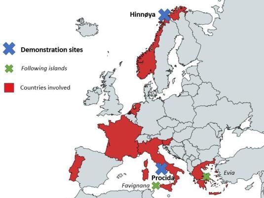
DELIVERABLE 2.2 – VERSION 1.2
                                       WORK PACKAGE N° 2

 Nature of the deliverable
 R            Document, report (excluding the periodic and final reports)                                   ✓
 DEM          Demonstrator, pilot, prototype, plan designs
 DEC          Websites, patents filing, press & media actions, videos, etc.
 OTHER        Software, technical diagram, etc.

 Dissemination Level
 PU     Public, fully open, e.g. web                                                                        ✓
 CO      Confidential, restricted under conditions set out in Model Grant Agreement
 CI      Classified, information as referred to in Commission Decision 2001/844/EC

 Quality procedure
 Date            Version    Reviewers                    Comments
 02/09/2019      0          Olivier GENEST (Trialog),    Creation of the document structure
                            Lizhen HUANG (NTNU)
 18/11/2019       1         Inputs     from       all    Inclusion of the contributions from different partners:
                            consortium partners          see section 3
 19/12/2019       2         Reviews     from      all    Final version reviewed by consortium partners, with a
                            consortium     partners.     formal review from WP3 (Lizhen HUANG, NTNU)
                            Formal review from
                            Lizhen HUANG (NTNU)

ACKNOWLEDGEMENTS

This report is part of the deliverables from the project "GIFT" which has received funding from the European
Union’s Horizon 2020 research and innovation program under grant agreement No 824410.

More information on the project can be found at http://www.gift-h2020.eu/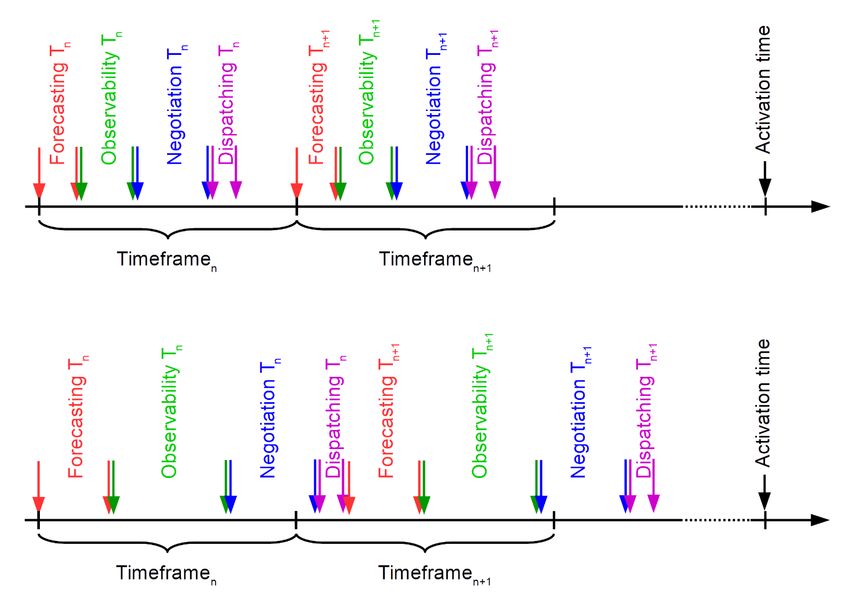
EXECUTIVE SUMMARY

This document details the Requirements for the GIFT project: it contains a description of the transversal
requirements that need to be fulfilled by all solution providers. This includes technical requirements as well
as more generic and functional requirements. The different requirements have been written by consortium
partners, according to their expertise and interests.
These requirements are meant to be updated during the lifetime of the project to reflect any change that
may arise: a final version will be delivered at the end of the project.
This document is organized in seven main sub-sections, corresponding to the different requirements:
Interoperability, Response time, Communication security, Privacy and data protection, Accuracy, Equity and
Visualisation of flexibility incentives.

TABLE OF CONTENTS

ACKNOWLEDGEMENTS ............................................................................................................................................... 1
EXECUTIVE SUMMARY ................................................................................................................................................ 2
TABLE OF CONTENTS ................................................................................................................................................... 2
LIST OF FIGURES .......................................................................................................................................................... 3
LIST OF TABLES ............................................................................................................................................................ 3
1. INTRODUCTION .................................................................................................................................................. 4
1.1.       SCOPE OF THE DOCUMENT ........................................................................................................................................ 4
1.2.       ABOUT GIFT .......................................................................................................................................................... 4
1.3.       GLOSSARY ............................................................................................................................................................. 5
     1.3.1.     Definitions ................................................................................................................................................. 5
     1.3.2.     Acronyms .................................................................................................................................................. 5
2. REQUIREMENTS .................................................................................................................................................. 7
2.1.       INTEROPERABILITY .................................................................................................................................................. 8
     2.1.1.     Energy sector specificities ......................................................................................................................... 8
     2.1.2.     Main measures to apply ......................................................................................................................... 11
2.2.       RESPONSE TIME.................................................................................................................................................... 12
     2.2.1.     Energy sector specificities ....................................................................................................................... 13
     2.2.2.     Needs in GIFT .......................................................................................................................................... 13
     2.2.3.     Main measures to apply ......................................................................................................................... 16
2.3.       COMMUNICATION SECURITY ................................................................................................................................... 17
     2.3.1.     Energy sector specificities ....................................................................................................................... 17
     2.3.2.     Needs in GIFT .......................................................................................................................................... 17
     2.3.3.     Main measures to apply ......................................................................................................................... 18
2.4.       PRIVACY AND DATA PROTECTION.............................................................................................................................. 19
     2.4.1.     Energy sector specificities ....................................................................................................................... 19
     2.4.2.     Needs in GIFT .......................................................................................................................................... 20
     2.4.3.     Main measures to apply ......................................................................................................................... 20
2.5.       ACCURACY ........................................................................................................................................................... 21
     2.5.1.     Energy sector specificities ....................................................................................................................... 21
     2.5.2.     Needs in GIFT .......................................................................................................................................... 21
     2.5.3.     Main measures to apply ......................................................................................................................... 22
     2.5.1.     Main measures to apply ......................................................................................................................... 24
2.6.       EQUITY ............................................................................................................................................................... 24
     2.6.1.     Energy sector specificities ....................................................................................................................... 25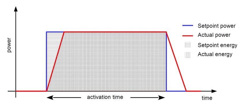
2.6.2. Needs in GIFT .......................................................................................................................................... 25
2.6.3. Main measures to apply ......................................................................................................................... 25
2.7. VISUALISATION OF FLEXIBILITY INCENTIVES ................................................................................................................. 26
2.7.1. Energy sector specificities ....................................................................................................................... 26
2.7.2. Needs in GIFT .......................................................................................................................................... 26
2.7.3. Main measures to apply ......................................................................................................................... 27
3. REFERENCES ...................................................................................................................................................... 27
4. ANNEXES .......................................................................................................................................................... 29
4.1. ANNEX A: RESPONSE TIME REQUIREMENTS AND ENERGY SECTOR SPECIFICITIES ................................................................ 29
LIST OF FIGURES
Figure 1: GIFT involved partners and pilot sites ................................................................................................. 5
Figure 2: Interactions between the GIFT system components .......................................................................... 8
Figure 3: The SGAM framework [2] .................................................................................................................10
Figure 4: GIFT generic system architecture ......................................................................................................12
Figure 5: Example showing the influence of time delays in the energy delivery deviation .............................14
Figure 6: Examples of timely (up) and delayed (down) completion of actions during a timeframe ...............16
Figure 7: Data exchange in relation with the operational phase .....................................................................23
Figure 8: Accuracy implications at module level ..............................................................................................23
Figure 9: Activation level and timescale of flexibility in different categories of service² ................................31
Figure 10: Future perspective on activation timescale in different categories of frequency reserves3 ..........32
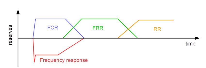
Figure 11: Indicative sequence of frequency reserves activation ....................................................................32
LIST OF TABLES
Table 1: Sub-requirements for Interoperability ...............................................................................................12
Table 2: Indicative iteration and implementation times for the various ICT components .............................15
Table 3: Sub-requirements for Response time ................................................................................................17
Table 4: Sub-requirements for Communication Security .................................................................................19
Table 5: Sub-requirements for Privacy and Data Protection ...........................................................................21
Table 6: Sub-requirements for Accuracy ..........................................................................................................24
Table 7: Sub-requirements for Equity ..............................................................................................................25
Table 8: Sub-requirements for Visualisation of flexibility incentives ...............................................................27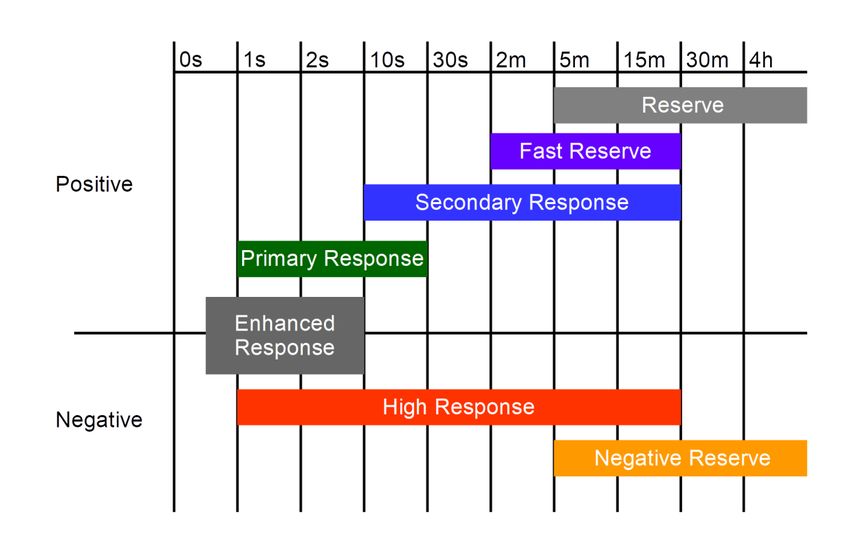
1. INTRODUCTION

1.1. SCOPE OF THE DOCUMENT

The goal of this deliverable is to define the main requirements that are to be fulfilled by the solution
providers. It explains what is to be implemented, and which of the GIFT solutions are concerned.
The seven requirements are technology-neutral, and each of them is defined by five questions:
    •   What does this requirement consist in, and why is it necessary?
    •   Are there any constraints from the fact that GIFT is situated within the energy sector?
    •   To which of the GIFT solutions does this requirement apply?
    •   What measures are requested to be implemented by the solutions?
    •   Which standards are being used to describe the requirement?

In order to be relevant through the duration of the project, the requirements will be updated during its
lifetime:
     • If new standards/regulations are published;
     • If significant changes occur within the project affecting the relevance of one requirement or making
         the definition of a new requirement necessary.
The measures to apply for each requirement are regrouped in a table at the end of the description to enable
future controls of the compliance.

The different requirements have been written by consortium partners, according to their expertise and
interests. This document is public, and will be used for the general public to understand what is done by the
GIFT project, and internally to ensure a common understanding of the use-cases and architecture of the
project.

1.2. ABOUT GIFT

GIFT is a project funded by the European Commission, that was launched in January 2019. It aims to
decarbonize the energy mix of European islands. Therefore, GIFT has the objective to develop innovative
systems that allow islands to integrate large share of renewable energies while not adding stress to the grid,
through the development of multiple innovative solutions, that will be combined into a complex system.
These solutions include a Virtual Power System (VPS), a state estimation of the grid, a better prediction of
supply and demand and visualization of those data through a GIS platform, and innovative storage systems
allowing synergy between electrical, heating and transportation networks. It will moreover help to implicate
the consumers in the energy transition, through various, energy management systems for harbors, factories,
battery and hydrogen storage and mobility that are being developed within the project.
In order to be representative and relevant when proposing solutions at the EU level, GIFT has selected several
islands and demonstration sites having their own issues and specificities. The GIFT partners will therefore
develop and demonstrate the solutions in two pilot islands, Hinnøya, Norway’s largest island, and Procida, a
small island in Italy, and study the replicability of the solution at least in the Greek island of Evia and the
Italian island of Favignana.
Figure 1: GIFT involved partners and pilot sites

1.3. GLOSSARY

1.3.1. Definitions

    Term                                                Definition
 Measure        The application of a methodology or the addition of a device to ensure the realisation of
                an aim.
 Requirement    A basic need of the GIFT project detailed within this document.
 Solution       Technology provided and used within the GIFT project to fill a need.
 Specificity    An aspect of the requirement that represents a constraint to its development.

1.3.2. Acronyms

     Term                                                Definition
 ACE            Area Control Error
 BESS           Battery Energy Storage Systems
 BRP            Balance Responsible Party
 DER            Distributed Energy Resources
 DSO            Distribution System Operator
 EMS            Energy Management System
 ESB            Enterprise Service Bus
 FCR            Frequency Containment Reserves
 FRR            Frequency Restoration Reserves
 GDPR           General Data Protection Regulation
 GIS            Geographical information system
 MDMS           Meter Data Management System
 PFC            Primary Frequency Control
 RES            Renewable Energy Sources
 SCADA          Supervisory Control And Data Acquisition
S&D   Supply and Demand
SFC   Secondary Frequency Control
SOC   Statement Of Compliance
TSO   Transmission System Operator
UC    Use-Case
VPS   Virtual Power System
2. REQUIREMENTS

The system requirements are linked to functionalities to be implemented within the GIFT project. The
functionalities will be executed by individual components, which are connected (from communication point
of view) between themselves as defined by the system architecture presented in [1].

The GIFT architecture is composed of the following main components:
    • Prediction of grid operation: performed based on weather forecasts, supply and demand prediction,
        and energy price information. The necessary inputs for prediction are acquired from external
        systems via the ESB. The most relevant outputs are predicted consumption and production in
        individual nodes of the grid during predefined time intervals in the future; the outputs are
        communicated to grid monitoring;
    • Grid Observability System: based on data received from SCADA and MDMS systems, the grid
        observability system continuously monitors the state of the grid. In combination with results
        received from module for prediction of grid operation, the grid monitoring estimates the current
        and future operational conditions in the grid and detects present or potential threats (e.g. network
        congestions, deterioration of voltage conditions) that could endanger the reliability of grid operation
        and security of supply of energy to final customers. If the Grid Observability module estimates the
        detected threats can be solved by demand response, it asks VPS (via the Flex Agent, in form of
        flexibility request) for provision of demand response in the relevant areas of the grid;
    • Energy Management System (EMS): systems implemented at final customers (consumers,
        producers, prosumers) for optimisation of energy consumption/production. In the GIFT system they
        provide information to VPS (via Flex Agent) about current and planned operation, and about
        flexibility potential (flex offers) available in individual time periods in the future. xEMS is a general
        term describing all types of EMSs (Ship/Harbour EMS, EV + Charging stations, Factory EMS, Smart
        Energy Hub, HBr storage – see also section 2.1.1.1);
    • Virtual Power System (VPS): the core of the GIFT system that acquires flexibility requests from Grid
        Observability System and flexibility offers from xEMSs (all via Flex Agents), matches them and
        requires from selected xEMSs the activation of their flexibility potential. In relation to xEMSs the VPS
        acts also as the aggregator of services offered by xEMSs;
    • Enterprise Service Bus (ESB): manages the information flow between systems developed in the
        project at the level of the control centre e.g. Prediction, Grid Observability; as well as external ones
        e.g. SCADA providing grid sensing data, MDMS providing measurements from smart metering
        equipment, weather services providing weather forecasts;
    • Flex Agent (FA): manages the information flow between xEMSs and VPS, and between Grid
        Observability System and VPS.
Besides, GIFT will also have GIS based digital twin to visualise the information from DSO and Project through
ESB. The GIFT system architecture is presented in Figure 2.Error! Reference source not found. (from the
deliverable D2.1 [1]):
Figure 2: Interactions between the GIFT system components
2.1. INTEROPERABILITY
Interoperability is defined as “the ability of two or more networks, systems, devices, applications, or
components to interwork, to exchange and use information in order to perform required functions” [2].
Interoperability is important for coordinated operation of several technologies (system components),
partners, and demo sites. If we adhere to the widely used standards for communication between
components, we ensure that our components can be integrated into different environments. The use, in the
same system, of devices (or software) from different vendors (manufacturers) allows to take advantage of
the characteristics of a wider range of devices, with both technical and economic benefits.
In this project, interoperability will allow a seamless and easy integration of the components developed by
the several partners.
2.1.1. Energy sector specificities
Energy sector with its ambition to decarbonize and enable high electricity production from RES drives the
need for sector coupling and involvement of final customers in operation of the grid and energy market.
Interoperability in that respect needs to address different systems, such as electric energy system, heating
system, cooling system, water system and transport.
From the energy perspective, this requirement will need to address different energy vectors besides electric
energy, such as heating and cooling energy.
In this energy sector, there is a wide range of standards that cover all possible applications. Among these
standards according to IEC [3], some are seen as the backbone of future smart grids. These standards are the
following:
• IEC 61970/61968: CIM (Common Information Model). Applying mainly to: Generation management
systems, EMS (Energy Management System); DMS (Distribution Management System); DA(Distribution Automation); SA (Substation Automation); DER (Distributed Energy Resource); AMI
(Advanced Metering Infrastructure); DR (Demand Response); E-Storage
• IEC 62325: CIM (Common Information Model) based, Energy market information exchange. Applying
mainly to: Generation management systems, EMS (Energy Management System); DMS (Distribution
Management System); DER; AMI; DR; meter-related back-office systems; E-Storage
• IEC 61850: Power Utility Automation, Hydro Energy Communication, Distributed Energy Resources
Communication. Applying mainly to: Generation management systems, EMS; DMS; DA; SA; DER E-
Storage; E-mobility
• IEC 62056: COSEM. Applying mainly to: DMS; DER; AMI; DR; Smart Home; E-Storage; E-mobility Data
exchange for meter reading, tariff and load control.
• IEC 62351: Applying mainly to Security for all systems
• IEC 61508: Applying mainly to Functional safety of electrical/electronic/programmable electronic
safety-related systems.
• IEC/IEEE 80005-1 High voltage energy supplies from grid (port) to ships recommending 11 kV AC
50Hz, 690 V AC 50Hz and 400 V AC 50Hz. Norwegian electric ferries (eFerry) will have 22 kV system
voltage from grid (DSO) and testing 11 + 11 kV sub-stations to handle both 11 kV and 22 kV.
• IEC/IEEE 80005-3 Low voltage energy supplies from grid to ships 690 V. Norway is recommending
400 V and 125 A.
Together with the above standards, there is also a subset of them that are deemed important for the
operation of Smart Grids:
• IEC 62357: Power utilities Reference Architecture – SOA. Applying mainly to: Energy Management
Systems; Distribution Management Systems; DER operation systems, market & trading systems, DR
systems, meter-related back-office systems
• IEC 60870-5: Telecontrol. Applying mainly to: EMS; DMS; DA; SA
• IEC 60870-6: TASE2 Inter Control Centre Communication. Applying mainly to: EMS; DMS
• IEC/TR 61334: ― “DLMS” Distribution Line Message Specification. Applying mainly to: AMI
• IEC 61400-25: Wind Power Communication. Applying mainly to: DER operation systems (Wind
farms); EMS; DMS;
• IEC 61851: EV-Communication. Applying mainly to: E-mobility (related further to Home & Building
energy management systems);
• ISO/IEC 15118 Road vehicles — Vehicle to grid communication interface. Applying mainly to: smart
charging
• IEC 62051-54/58-59: Metering Standards. Applying mainly to: DMS; DER; AMI; DR; Smart Home; E-
Storage; E-mobility
• IEC 61968: Application integration at electric utilities - System interfaces for distribution
management.
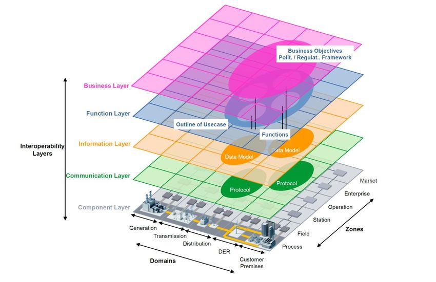
Due to the large number of standards, the use of a specific framework, such as the Smart Grid Architecture
Model (SGAM), allows a systematic approach in terms of interoperability and architecture analysis. The
SGAM framework consists of different interoperability layers as shown in Figure 3, which includes
components, communication, information, function and business processes. SGAM enables users to
represent Smart Grid Use Cases graphically in a technology neutral manner facilitating the identification of
key interoperability aspects.Figure 3: The SGAM framework [2]
In the domains/zones/layers of SGAM various subsets of relevant standards can be allocated. An exhaustive
list of international standards and their mapping on the various SGAM domains is listed in [2].
Needs in GIFT
In GIFT project, there are two main interoperability needs:
a) The system is comprised by several modules, developed by different entities in need of information
sharing, so that its functions can be fulfilled: Grid Observability, Prediction, GIS TWIN, etc.; whilst
external systems need to be interfaces as well: MDMS, SCADA, weather services. This is tackled by
the Enterprise Services Bus (ESB) developed by ICOM.
2.1.1.1. Grid Observability System and several EMS systems from different manufacturers
must communicate with the same trading system – this is tackled by the Flex Agent
elements using the xEMS communication protocol for communication between xEMS
and Flex Agent, and the Flex Offer protocol for communication between VPS and Flex
Agent (towards xEMSs and Grid Observability System), both developed by INEA.ESB
The information exchanges identified so far in GIFT, especially those exchanged with the different
stakeholders and components of the energy system could follow the aforementioned standards.
For example, if it was chosen to follow the information model for measurement data described in CIM (i.e.
IEC 61968-9), will increase the interoperability of the ESB and the components receiving data from metering
units.
In addition, one must notice that the existence of information models for some type of information, such as
forecast is not available in CIM. Nevertheless, CIM is highly extensible, hence existing classes of the standard
can be utilized as a basis for structuring new information models.2.1.1.2. Flex Agent, xEMS communication protocol and Flex Offer
Interoperability applies to FlexAgent, which connects external Energy management systems (EMS) at
prosumer’s level to VPS. These EMS systems are:
- Ship/Harbour EMS – battery,
- Electric vehicles + Charging stations,
- Factory / Commercial EMS – virtual storage – energy shifting in time and adapting energy,
- Smart Energy Hub – Battery and Hydrogen storage system,
- H-Br battery storage – “flow” battery.
Additionally, this dedicated Flex Agent is used for the connection of grid operator control system with the
open market (VPS).
Flex Agent needs to address technical specifics for all system components and solutions at prosumer’s level
and properly translate them into communication parameters. This will lead, if required, to the upgrade of
xEMS communication protocol with introduction of new identified parameters, adapted to technical
properties of different EMS solutions and underlaying components.
2.1.2. Main measures to apply
2.1.2.1. ESB
Define a consolidated model of information exchange (Canonical Data Model) for information exchange with
the ESB.
Survey if technology providers are interested in engaging in a CIM based design, hence increasing the
interoperability of the overall solution.
2.1.2.2. Flex Agent and Flex Offer
Flex Agent needs to implement measures that will provide a complete and operational solution. This
comprehends the hardware, a detailed definition of communication protocol, a physical layer and an
informational one (such as Modbus TCP/IP, Modbus RTU (RS-485), JSON (REST or MQTT).
The importance of Flex Agent interoperability between building blocks is shown in GIFT System Architecture.
On Figure 4 dashed red lines represent the system components using Flex Offer protocol as an exchange
protocol and dashed green line represents xEMS communication protocols. Flex Offer protocol was initially
developed in project MIRABEL and further enhanced in project GOFLEX .Figure 4: GIFT generic system architecture
The interoperability on prosumers level/location (different types of prosumers) is provided by the Flex
Agents. They address different types of prosumers. That approach provides the potential for further
expansion of the solution – the technology is interoperable and can include different types of prosumers.
On the higher level, modification of Flex Offer protocol with additional parameters for flexibility pricing is
used for communication between VPS and Grid Observability system.
2.1.2.3. Summary
Table 1: Sub-requirements for Interoperability
ID Description Actors
Req. 1.1 Define a consolidated model of information exchanges (Canonical Data Model) ESB
Req. 1.2 Survey if technology providers are interested in engaging in a CIM based design ESB
Req. 1.3 Implement measures for hardware, detailed definition of communication protocol, FlexAgent
physical layer and informational level, that will provide complete and operational
solution.
2.2. RESPONSE TIME
In smart grids the different components can introduce delays in their response which may result in sub-
optimal, erroneous or unstable behaviour of the system. Thus, the corresponding components used in GIFT
should meet some specific response time requirements. These requirements are analysed in the followingsections. 2.2.1. Energy sector specificities It can be safely assumed that the three main categories of components in a smart grid are control, communication and power components. Each of these components introduces a time delay in the process which may result in erroneous behaviour. Also, from a process phases point of view we can assume that in smart grids we have scheduling, and activation of flexibility as two distinct phases. Depending on the type of components and different process phases there are different response time requirements even though there is not a systematic approach with regard to every existing application. There are, however, in literature specific requirements with regard to activation time of flexibility for various types of ancillary services as defined in [4] and [5] as well as the scheduling time defined in [6]. These requirements are considered in order to determine the response time requirements of the GIFT solutions. A more analytical presentation of these requirements is given in Annex A. 2.2.2. Needs in GIFT According to the selected UCs for demonstration GIFT deals mainly with procedures related to the Active Energy Flexibility. In such case the activation timescales of the various DER will range from 1hour and above even though the scenario of 15min activation and below should not be excluded. In this regard we should consider the minimum activation time as worst-case scenario for the response time requirements of the components. Also, the GIFT solutions deal mostly with the scheduling phase of the process rather than the real-time activation of flexibility which means that the response requirements are mostly related to the communication and control components and only partly to the power components. For the scheduling procedure we should consider a worst-case scenario in which the process is Intra Day with 1-hour minimum time horizon between scheduling and activation of flexibility. Depending on the temporal resolution of flexibility the scheduling procedure may be either 1 hour or 15 minutes, and going down to a few minutes (1 min) in future evolution of flexibility trading based on dynamic prices. As it can be seen in Figure 4 the composite system consists of various power components, control blocks and communication channels. During the flexibility activation time, the power components need to respond fast enough in order to avoid deviations between the scheduled and delivered energy during the activation time. As can be seen in Figure 5 a time delay in the response of a DER unit such as the ramp-up time may result in a deviation from the requested energy for the specific timeframe. This deviation if aggregated for all prosumers may have detrimental effects on the grid (i.e. congestion state or voltage deviations could be deteriorated instead of improved). The response times discussed above are applicable to active energy flexibilities. The specific needs of reactive energy trading will be addressed within the design phase of concrete demonstration case.
Figure 5: Example showing the influence of time delays in the energy delivery deviation

The DER components used in our demonstrations are Battery Energy Storage Systems (BESS), Electric Vehicle
charging stations, Industrial / Commercial prosumers and electrically supplied ships. Each of these units
communicate with a local Energy Management System (EMS) which specifies the set-points or schedule of
active/reactive power in order for the unit to deliver/consume a specific amount of energy. Technologically
speaking all these units, and in particular the batteries, shall have response times to set-point changes in the
timescale of less than one second because they are interconnected to the grid via power electronics.
For example, the Sylfen hydrogen rSOC system module, due to electrochemical and thermal limitations,
reacts in less than 1 hour. As the Sylfen system contains both technologies, the response time will be less
than 1 sec for the battery module (up to +/- 25 kW depending of the state of charge, then the rSOC module
will join the battery with a power of (+5 kWe max in fuel cell mode and – 40 kWe in electrolyser mode).
Considering now that the activation time is in the scale of hour(s) (or 15 min; or 1min) it is self-evident that
the response time of the selected DER is rather negligible. Also, the time delay to communication between
the local EMS and the corresponding DER is significantly less than this activation time. Thus, it has minimal
impact on the overall system behaviour.
This is also the case for the Elestor battery that has a technical response time that is between a part of a
second and, in case the battery is in a standby mode where its electrolyte pump is switched off, potentially
a few seconds. It will be possible to control in which standby mode the battery is made available. Also, in
these operative modes, the response time is significantly less than the required scale of the activation time.
A similar observation is valid also for EV charging system. The reaction time of EV battery management
system is negligible – the charging power is modified according to load set point received from EV station
within few seconds. Some delays can be experienced if there are several EV stations installed at the same
final customer (i.e. fed via the same grid connection point). In this case the charging system must distribute
the EV charging set point (which is common for all current charging sessions) to individual EVs (charging
sessions). The algorithms used for distribution of common required load to individual sessions are quite
complex and involve user needs (delivery of required amount of energy till departure time), technical
characteristics (rated current, number of phases) of power supply, EV chargers’ components and charging
cable, and technical characteristics of EV on-board charger (number of phases, rated current/phase). The
calculation might take several (
It is worth noting here that the communication latencies during this phase are expected to be rather
negligible (timescale of sub-seconds) compared to the response time of the various algorithmic blocks.

          Figure 6: Examples of timely (up) and delayed (down) completion of actions during a timeframe

2.2.3. Main measures to apply

Considering the concepts presented in the previous two subsections we can assume some concrete
requirements regarding the various GIFT components. It is noteworthy here that the response time of the
power components could result in overshoots of power due to oscillations around the setpoint especially in
step changes. Because of that in some cases the introduction of ramp-up or down time limitation may be
beneficial. In any case, in order to ensure that there is no impact on the flexibility activation the total response
time of the subsystem EMS+DER should not exceed 5 seconds which is
latencies of the communication components should be at the scale of sub-second. Table 3 summarises the
requirements with regard to response time.
ID Description Actors
Req. 2.1 Ensure that the total response time of the subsystem EMS+DER does not exceed EMS, DER
5 seconds.
Req. 2.2 Account for time delays during activation in the resulting energy. Dispatching
algorithm
Req. 2.3 Ensure the aggregate response time of the whole procedure of control Observability
components is less than 5min. system, VPS
Req. 2.4 Ensure the latencies of the communication components are at the scale of sub- ESB,
second. FlexAgent
Table 3: Sub-requirements for Response time
2.3. COMMUNICATION SECURITY
Cybersecurity in energy sector projects is essential, as cyberattack on the communication medium of a device
could lead to an outage, and possibly cascading effects. Therefore, the communication security is required
to be considered and specified in all the solutions that will be deployed within the project GIFT.
2.3.1. Energy sector specificities
The energy sector has some specificities that have to be considered when designing the communication
security, and it needs to stay secure and operable under any circumstances. These specificities should be
addressed while designing the communication devices and security protocols. According to the Commission
Recommendations on cybersecurity in the energy sector published by the European Commission [7], three
main specificities should be considered:
• Cascading effects: in energy networks, a fault at one device can have repercussions in the overall
network.
• Legacy technology: the legacy of devices that have a lifetime of 30-60 years have to interact with the
most recent technologies.
• Real-time requirements: many devices in the energy sector must respond in real-time, which puts a
very high constraint to the overall system.
Depending on the context, additional specificities should be considered, such as availability: energy systems
communication networks need to stay available and operable, even when external communication networks
are down.
2.3.2. Needs in GIFT
The security in communications in GIFT extends from communication between devices to communication
among systems. These are enabled by two systems: the ESB handles the communication at the level of the
control centre, among the Prediction system, the Grid Observability system, and the systems of BRP, DSO
and municipalities (e.g. MDMS) as well as external systems (e.g. weather services); the Flex Agent manages
the communication between the VPS and the flexibility providers and Grid observability system. Moreover,the EMS systems ensures the communication to the field devices, and therefore are concerned by the
communication security issues.
Secure communications must be established among the above elements as well as to interfaces to end-users.
2.3.3. Main measures to apply
The solutions should ensure physical devices, communication protocols and stored data are protected
against cyberattacks. This implies at least implementing the following measures.
The following standards should be considered to implement the cybersecurity measures within the GIFT
Project:
• The Cybersecurity Act [8] aims to share a common cybersecurity framework within the EU. It also
provides a certification framework [9].
• ISO/IEC 27100 Cybersecurity – Overview and Concepts, ISO/IEC PDTS 27101 Cybersecurity
Framework Development Guidelines [10]
• ISO/IEC 27103 Cyber security and ISO and IEC standards [11] providing guidance on how to leverage
existing standards in a cybersecurity framework
• IEC Technology Report: Cyber security and resilience guidelines for the smart energy operational
environment [12]
2.3.3.1. Physical measures
Flex Agent and the ESB potentially need to communicate with some legacy devices/systems (i.e. MDMS).
Therefore, they should ensure that devices added to sites including legacy devices have a level of security
adapted to the site criticality.
For legacy devices, additional (local) proxy/firewall physical devices may be required to achieve the required
level of security. Then physical protection will be required to secure the link between the proxy device and
the legacy device. Moreover, critical nodes within the system should be identified, as candidate for addition
of redundancy nodes.
2.3.3.2. Protocols
The communication protocols among systems in GIFT solution like the ESB, Flex Agent, VPS should apply at
least the following principles, in order to ensure a sufficient level of security:
• Choose secure communication protocols, with encryption etc. for guaranteeing confidentiality of
information exchanged, e.g. using cryptographic protocols over HTTP.
• Follow best practice in certificate management for digital certificates,
• Follow standards practice like the one suggested in ISO/IEC PDTS 27101 Cybersecurity Framework
Development Guidelines based on ISO/IEC 27100 Cybersecurity – Overview and Concepts [10].
• Introduce authentication, authorisation and revocation mechanisms
The entities should implement the proper identification and alarming processes for extraordinary events like
communication breakdown, data loss, authentication failure, etc.
2.3.3.3. Conservative approach of controlling algorithms
The communication protocol and controlling algorithms in VPS and Flex Agent should preserve the end user
load and electricity grid in case of extraordinary events like communication breakdown. If this happens, the
default behaviour of prosumer EMS controlling algorithms should override any information from Flex Agentand avoid propagating the damage to the user equipment. It should control the system as was before the
introduction of Flex Agent to offer flexibilities. This is in the scope of EMS system provider.
2.3.3.4. Anomaly detection from data
For devices that are not able to provide cryptographically secure computation capacity, particularly those
legacy devices, attacks on the data integrity should be modelled and methods for anomaly detection from
data stream should be designed and deployed to address these adversarial models.
2.3.3.5. Summary
Table 4: Sub-requirements for Communication Security
ID Description Actors
Req. 3.1 Ensure new devices have a level of security adapted to the site criticality Flex Agent
Req. 3.2 If necessary, to achieve the required level of security, add an additional Flex Agent, ESB
(local) proxy/firewall device for legacy devices, and physical protection to
secure the link between the proxy device and the legacy device.
Req. 3.3 Choose secure communication protocols, with encryption etc. for Flex Agent, ESB
guaranteeing confidentiality of information exchanged.
Req. 3.4 Introduce authentication, authorisation and revocation mechanisms Flex Agent, ESB
Req. 3.5 Identify critical nodes within the system, as candidate for addition of Flex Agent, ESB
redundancy nodes
Req. 3.6 Implement the proper identification and alarming processes for Flex Agent, ESB
extraordinary events
Req. 3.7 Preserve the end user load and electricity grid in case of extraordinary events EMS
Req. 3.8 Model attacks on the data integrity for devices that are not able to provide Flex Agent, EMS
cryptographically secure computation capacity and design and deploy
methods for anomaly detection from data stream to address these
adversarial models
2.4. PRIVACY AND DATA PROTECTION
The data that will be used in this project needs to be handled with precautions in order to ensure the respect
of the privacy of the users and the confidential data of companies.
2.4.1. Energy sector specificities
The main objective of the GIFT project is to decarbonise the energy mix of islands. This general ambition is
supported in the project by the following clear, measurable, realistic and achievable objectives:
• Allow a high level of local renewable energy sources penetration
• Provide visibility of the energy grid to better manage its flexibility and plan its evolutions
• Develop synergies between the electricity, heating, cooling, water and, transport networks
• Reduce the use of hydrocarbon-based energies
• Ensure the sustainability of the solutions and their replicability in other islands
In order to achieve these objectives, the GIFT project will have to collect data related to the following fields:
energy, transport (mobility), weather and climate change.The energy data, as described in the Data Management Plan, are for some of them private data of the
consumers and companies. These can be considered critical data in terms of privacy and should therefore be
handled with precautions.
2.4.2. Needs in GIFT
In the GIFT project, energy data are collected and handled by the Weather, Energy, S&D, Price Predictions
systems developed by RDN, NTNU and ARMINES, and by the Grid observability system performed by ODI.
Those information flows are facilitated by ESB (ICOM), flexibility and price data are collected and used by the
VPS (INEA).
Moreover, the ESB and Flex Agents systems are used for communication between devices, and therefore
handle sensible data.
All data in energy flexibility trading are contractual data between the trading parties and access to them is
limited to these parties.
The following standards should be considered to implement the data protection measures within the GIFT
Project:
• GDPR [13] for data protection and storage
• ISO/IEC TR 27019 [14] Information security management guidelines based on ISO/IEC 27002 for
process control systems specific to the energy utility industry (for controlling and monitoring the
generation, transmission, storage and distribution of electric power, gas and heat in combination
with the control of supporting processes).
• ISO/IEC 29101Privacy architecture framework (focusing on ICT systems that are designed to interact
with PII principals) [15]
• ISO/IEC 27018 Code of practice for PII protection in public clouds acting as PII processors [16]
2.4.3. Main measures to apply
2.4.3.1. Data collection, handling and storage
The project will avoid and prevent any unnecessary collection, use and storage of personal data. In case
personal data are nevertheless processed, ethics requirements in this regard will be taken into account,
especially in regard to the GDPR [13].
The personal data and data concerning privacy that need protection should be identified, then, depending
on specific types of data and their usage, adapted methods for protecting them should be adopted, such as
data aggregation, homomorphic encryption, blind signature, or local energy cache units. All contractual data
will be protected through access and retrieval rights.
2.4.3.2. Data communication
When applicable, only aggregated data will be transmitted between nodes, reducing the amount of personal
identifying data exchanged.All data will be protected during transit.
Table 5: Sub-requirements for Privacy and Data Protection
ID Description Actors
Req. 4.1 Avoid and prevent any unnecessary collection, use and storage of personal Weather, Energy,
data S&D, Price
Req. 4.2 Take into account ethics requirements when processing personal data, Predictions
especially in regard to the GDPR system, Grid
Req. 4.3 Identify the personal data and data concerning privacy that need observability
protection system, VPS, Flex
Req. 4.4 Adopt adapted methods for protecting data, depending on specific types Agent, ESB, GIS
of data and their usage. Twin
Req.4.5 Adopt methods for access and retrieval rights of all contractual data in Flex Agent, VPS,
flexibility contracts Price Predictions
system, Grid
observability
system, ESB
Req. 4.6 Flex Agent, ESB,
When applicable, only transmit aggregated data between nodes.
GIS Twin
Req. 4.7 Protect all data during transit. Flex Agent, ESB
2.5. ACCURACY
The GIFT system modules that must comply with accuracy requirements are the grid observability module
and the forecasting module. They should be accurate enough to be able to detect congestion in advance and
avoid blackouts.
2.5.1. Energy sector specificities
In the case of grid observability system, the estimated parameters are the voltage plan and the load of
defined critical assets. A voltage or power flow value is detected as a violation of the requirements if it is out
of the range of limits defined by the regulatory entity or the safety rules. Those limits are specific to each
demonstration site.
In the case of forecasting energy supply and demand, the error metric is inherently dependent on the type
of system being forecasted. The error of an aggregation as a National power system or a single household
have different ranges. For example, in [17], the Mean Absolute Percentage Error (MAPE) ranges between 1%-
2% for wide areas and between 20%-100% for individual consumers. Hence, for each one of the systems
being assessed, a relative improvement should be used comparing with a reference forecast result (or
persistence in the absence of one).
2.5.2. Needs in GIFT
GIFT project will establish a (near) real-time market of flexibilities. One of the needs of this market is to know
when problems will occur on the grid (congestion, voltage excursion, etc.) and what flexibility is needed to
solve the problem.The module “Modelling and observability of the grid” contributes to fulfil those needs and the main objective
of the project that is to decarbonise the energy mix of islands and is in particular highly linked to the specific
objective SO2: “Provide visibility of the energy grid to better manage its flexibility and plan its evolutions”.
This module will also contribute to the specific objective SO1 which is to “allow a high level of local renewable
energy sources penetration”, by enabling the use of flexibilities to solve congestion issues that renewable
energy sources might create on the grid.
The grid observability system will be used in GIFT project’s use cases to estimate voltage and current
congestion and to select the flexibilities to be activated to avoid and to mitigate these congestions.
The forecasting module addresses the specific objective SO2: “Provide visibility of the energy grid to better
manage its flexibility and plan its evolutions”. It provides short-term forecasting of energy supply and
demand, as well as day-ahead foresight on the prosumers’ opportunities for providing flexibility. These
forecasts are necessary to inform the negotiation in the local markets.
2.5.3. Main measures to apply
2.5.3.1. The first step is to provide a grid model: cf. deliverable 3.3
Network topology
• The network topology is obtained by analysing the relationships between voltages: the closest
voltages are, the closest the corresponding meters are. The influence of the medium voltage brings
complexity in this analysis as its fluctuation is important compared to the variation due to the low
voltage network. Several processes are used to remove this influence, to ensure the obtained
topology is radial, and to connect the three phases within the feeders.
Influence Matrix
• The influence matrix is built to show the influence of the power consumptions / productions on the
voltage map. The difficulty here is to only keep the direct connections: if A influences B and C, then
B and C are correlated, but that does not mean there is a direct link between them. Then, the
challenge is to find for each voltage, which power values are necessary to explain its fluctuations.
Network model
• In order to comply with the operational constraint which is the unavailability of smart meters data in
real time, another feature needs to be built. The new model should indeed be able to provide this
same estimation of the voltage map but using only the data of some selected smart meters – the
ones providing flexibility as they will send information to the control centre – and the data coming
from the substation. The challenge here is to be able to estimate the whole voltage map only from
few measurements. This will be done by relying on the previously found “influence matrix”, that gives
us the network behaviour.
2.5.3.2. Second step flexibility operation
This operation follows the scheme described in Figure 7. Both Forecast and Network model will be used to
predict the status of the grid in real time and in the next time step and to estimate the impact of the activation
of a flexibility on a given forecasted issue.
The visualisation part described in Figure 7 does not interfere with the operation of the system but allows
the user to see the main part of the process and assess its relevance.Figure 7: Data exchange in relation with the operational phase
2.5.3.3. Accuracy requirements for the two steps
The issue at stake with the accuracy in the flexibility market is economical. The more accurate are the
prediction and estimation, the smaller the flexibility to be activated will be. Therefore, the value for money
of the market for the DSO will be higher.
As described in the energy sector specificities, voltages must be maintained within the limits given by the
regulator while loads must be kept within the defined safety conditions of the critical asset.
The whole accuracy is impacted at each level by the accuracy of each module:
Figure 8: Accuracy implications at module level
For instance, the first experimentation on the grid of Hinnøya shows that the modelling by itself will generate
an error on the voltage prediction of less than 2V at LV level (400/230 V). Considering this accuracy, keeping
the voltage plan within the limits requires an accuracy from the other modules, including the activation of
the flexibilities, small enough to keep the global chain in a level of accuracy that allows the operation of the
system.
2.5.3.4. Measuring the accuracy of energy supply and demand forecasting
Forecasting of energy supply and demand is measured by a relative comparison between the accuracy of the
GIFT forecasting system and some reference method (persistence method, in the absence of other), on the
same application. This is because the accuracy range varies significantly depending on what is being
forecasted [17], [18]. This means that absolute accuracy targets should vary accordingly. To reflect this
requirement, it is proposed that the GIFT forecasting solution improve the reference method in each area by
10%.
Another relevant aspect to the accuracy measurement is the fact that MAPE cannot be calculated in certain
applications. By definition, this error measure cannot be applied to quantities with zero real values.
Nevertheless, in these cases Root Mean Square Error (RMSE) is going to be used.2.5.3.5. Measuring the accuracy of state estimation
As the state estimation system is a machine learning based algorithm, it will constantly learn from the
comparison of its state estimation results with the real value. The error will be monitored to adjust the model.
To communicate and follow the accuracy of the model, MAPE over a defined period will be used.
The objective set for the GIFT project is linked to the frequency of valid prediction of a congestion, so the
flexibilities are purposefully activated. This metric will be monitored as well, and the objective is to keep it
over 90%.
2.5.3.6. Measuring the accuracy of flexibility impact study
The accuracy of the impact study is critical in order to activate the relevant flexibility and solve the previously
forecasted issue. This accuracy is part of the KPI 1.2 “Avoid congestion: reduction of peak demand” which
refer to a global objective of the project as voltage issues are being considered too. It will be measured
comparing the forecasted impact with the real impact monitoring the MAPE at each activation of a flexibility
and comparing it with the MAPE of the state estimation without the activation of a flexibility.
2.5.4. Main measures to apply
Table 6: Sub-requirements for Accuracy
ID Description Actors
Req. 5.1 Keep error levels form other modules small enough to keep the global All components
chain in a level of accuracy that allows the operation of the system
Req. 5.2 Forecasting
GIFT forecasting solution should improve the reference method in each
area by 10% solution
Req. 5.3 Use Root Mean Square Error (RMSE) when MAPE cannot be calculated. Forecasting and
observation
systems
Req. 5.4 Monitor the error to adjust the model using MAPE over a defined period Forecasting and
observation
systems
Req. 5.5 Keep frequency of valid prediction of a congestion over 90% Forecasting and
observation
systems
Req. 5.6 Measure voltage issues comparing the forecasted impact with the real Forecasting and
impact monitoring the MAPE at each activation of a flexibility and compare observation
it with the MAPE of the state estimation without the activation of a systems
flexibility.
2.6. EQUITY
The different flexibility providers should be transparently requested and rewarded. This should be taken into
account regardless of their source type, technical specifics and type of prosumer (i.e. household, corporate,
business entity …). We have taken into account the assumption that price mechanism will properly address
CO2 free flexibility. Non-CO2 free prosumers will not be price competitive on the market due to fuel costs,You can also read