VMware vSphere 5.0 Security Target - Evaluation Assurance Level: EAL4+
←
→
Page content transcription
If your browser does not render page correctly, please read the page content below
®
VMware vSphere 5.0
Security Target
Evaluation Assurance Level: EAL4+
DOCUMENT VERSION: 0.7
VMware, Inc.
                                                   3401 Hillview Ave
                                                 Palo Alto, CA 94304
                                                United States of America

                                               Phone: +1 (650) 475-5000
                                               http://www.vmware.com

                                VMware Security Advisories, Certifications and Guides
                                        http://www.vmware.com/security/

                                            Prepared for VMware by:

                                               Corsec Security, Inc.
                                   13135 Lee Jackson Memorial Highway, Suite 220
                                                 Fairfax, VA 22033
                                               United States of America
                                              Phone: +1 (703) 267-6050
                                               http://www.corsec.com

Copyright © 2009–2012 VMware, Inc. All rights reserved. This product is protected by U.S. and international copyright and
intellectual property laws. VMware products are covered by one or more patents listed at
http://www.vmware.com/go/patents.

VMware is a registered trademark or trademark of VMware, Inc. in the United States and/or other jurisdictions. All other
marks and names mentioned herein may be trademarks of their respective companies.
Security Target, Version 0.7 April 19, 2012
Table of Contents
1 INTRODUCTION ................................................................................................................... 5
1.1 PURPOSE ................................................................................................................................................................ 5
1.2 SECURITY TARGET AND TOE REFERENCES ...................................................................................................... 5
1.3 PRODUCT OVERVIEW .......................................................................................................................................... 5
1.4 TOE OVERVIEW ................................................................................................................................................... 9
1.4.1 Brief Description of the Components of the TOE..................................................................................... 10
1.4.2 TOE Environment ................................................................................................................................................ 12
1.5 TOE DESCRIPTION ............................................................................................................................................12
1.5.1 Physical Scope....................................................................................................................................................... 13
1.5.2 Logical Scope ........................................................................................................................................................ 14
1.5.3 Product Physical/Logical Features and Functionality not included in the TOE ................................. 18
2 CONFORMANCE CLAIMS .................................................................................................. 19
3 SECURITY PROBLEM .......................................................................................................... 20
3.1 THREATS TO SECURITY......................................................................................................................................20
3.2 ORGANIZATIONAL SECURITY POLICIES ..........................................................................................................21
3.3 ASSUMPTIONS .....................................................................................................................................................21
4 SECURITY OBJECTIVES ...................................................................................................... 22
4.1 SECURITY OBJECTIVES FOR THE TOE ..............................................................................................................22
4.2 SECURITY OBJECTIVES FOR THE OPERATIONAL ENVIRONMENT..................................................................23
4.2.1 IT Security Objectives ......................................................................................................................................... 23
4.2.2 Non-IT Security Objectives ............................................................................................................................... 23
5 EXTENDED COMPONENTS .............................................................................................. 24
5.1 EXTENDED TOE SECURITY FUNCTIONAL COMPONENTS ...........................................................................24
5.1.1 Class FAU: Security Audit .................................................................................................................................. 25
5.1.2 Class FIA: Identification and authentication ................................................................................................ 27
5.1.3 Class EXT_VDS: Virtual machine domain separation ............................................................................ 28
5.2 EXTENDED TOE SECURITY ASSURANCE COMPONENTS..............................................................................29
6 SECURITY REQUIREMENTS .............................................................................................. 30
6.1 CONVENTIONS ...................................................................................................................................................30
6.2 SECURITY FUNCTIONAL REQUIREMENTS ........................................................................................................30
6.2.1 Class FAU: Security Audit .................................................................................................................................. 32
6.2.2 Class FCS: Cryptographic Support ................................................................................................................. 34
6.2.3 Class FDP: User Data Protection .................................................................................................................... 35
6.2.4 Class FIA: Identification and Authentication................................................................................................ 36
6.2.5 Class FMT: Security Management ................................................................................................................. 37
6.2.6 Class FPT: Protection of the TSF ..................................................................................................................... 41
6.2.7 Class FTA: TOE Access ...................................................................................................................................... 41
6.2.8 Class EXT_VDS: Virtual Machine Domain Separation ........................................................................... 41
6.3 SECURITY ASSURANCE REQUIREMENTS ...........................................................................................................42
7 TOE SUMMARY SPECIFICATION ..................................................................................... 43
7.1 TOE SECURITY FUNCTIONS .............................................................................................................................43
7.1.1 Security Audit ........................................................................................................................................................ 44
7.1.2 Alarm generation ................................................................................................................................................. 44
7.1.3 Cryptographic Support ....................................................................................................................................... 45
7.1.4 User Data Protection .......................................................................................................................................... 45
7.1.5 Identification and Authentication.................................................................................................................... 46
7.1.6 Security Management ........................................................................................................................................ 47
7.1.7 Protection of the TOE Security Functions .................................................................................................... 48
7.1.8 Virtual Machine Domain Separation ............................................................................................................ 48
VMware vSphere 5.1 Page 3 of 63
© 2012 VMware, Inc.
This document may be freely reproduced and distributed whole and intact including this copyright notice.Security Target, Version 0.7 April 19, 2012
7.1.9 TOE Access ............................................................................................................................................................ 49
8 RATIONALE .......................................................................................................................... 50
8.1 CONFORMANCE CLAIMS RATIONALE .............................................................................................................50
8.2 SECURITY OBJECTIVES RATIONALE ..................................................................................................................50
8.2.1 Security Objectives Rationale Relating to Threats .................................................................................... 50
8.2.2 Security Objectives Rationale Relating to Policies ..................................................................................... 53
8.2.3 Security Objectives Rationale Relating to Assumptions ........................................................................... 53
8.3 RATIONALE FOR EXTENDED SECURITY FUNCTIONAL REQUIREMENTS ......................................................53
8.4 RATIONALE FOR EXTENDED TOE SECURITY ASSURANCE REQUIREMENTS ...............................................54
8.5 SECURITY REQUIREMENTS RATIONALE ...........................................................................................................55
8.5.1 Rationale for Security Functional Requirements of the TOE Objectives ............................................ 55
8.5.2 Security Assurance Requirements Rationale ............................................................................................... 57
8.5.3 Dependency Rationale ....................................................................................................................................... 58
9 ACRONYMS AND TERMS ................................................................................................... 60
Table of Figures
FIGURE 1 – SAMPLE DEPLOYMENT CONFIGURATION OF THE TOE...................................................................................9
FIGURE 2 – PHYSICAL TOE BOUNDARY ............................................................................................................................. 13
FIGURE 3 – EXT_FAU_ARP SYSTEM EVENT AUTOMATIC RESPONSE FAMILY DECOMPOSITION ................................ 25
FIGURE 4 – EXT_FAU_STG EXTERNAL AUDIT TRAIL STORAGE.................................................................................... 26
FIGURE 5 – EXT_FIA_VC_LOGIN VCENTER SERVER USER LOGIN REQUEST FAMILY DECOMPOSITION ................. 27
FIGURE 6 – EXT_VDS_VMM: ESXI VIRTUAL MACHINE DOMAIN SEPARATION FAMILY DECOMPOSITION............... 28
List of Tables
TABLE 1 – ST AND TOE REFERENCES ....................................................................................................................................5
TABLE 2 – COMPONENTS OF THE TOE .............................................................................................................................. 14
TABLE 3 – CC AND PP CONFORMANCE ............................................................................................................................ 19
TABLE 4 – THREATS ............................................................................................................................................................... 20
TABLE 5 – ASSUMPTIONS ...................................................................................................................................................... 21
TABLE 6 – SECURITY OBJECTIVES FOR THE TOE ............................................................................................................... 22
TABLE 7 – IT SECURITY OBJECTIVES .................................................................................................................................... 23
TABLE 8 – NON-IT SECURITY OBJECTIVES ......................................................................................................................... 23
TABLE 9 – EXTENDED TOE SECURITY FUNCTIONAL REQUIREMENTS ........................................................................... 24
TABLE 10 – TOE SECURITY FUNCTIONAL REQUIREMENTS ............................................................................................. 30
TABLE 11 – AUDITABLE EVENTS ON THE ESXI .................................................................................................................. 32
TABLE 12 – CRYPTOGRAPHIC OPERATIONS ...................................................................................................................... 34
TABLE 13 – MANAGEMENT OF TSF DATA ......................................................................................................................... 37
TABLE 14 – ASSURANCE REQUIREMENTS ............................................................................................................................ 42
TABLE 15 – MAPPING OF TOE SECURITY FUNCTIONS TO SECURITY FUNCTIONAL REQUIREMENTS ........................ 43
TABLE 16 – AUDIT RECORD CONTENTS............................................................................................................................ 44
TABLE 17 – THREATS:OBJECTIVES MAPPING ...................................................................................................................... 50
TABLE 18 – ASSUMPTIONS:OBJECTIVES MAPPING ............................................................................................................. 53
TABLE 19 – OBJECTIVES:SFRS MAPPING ............................................................................................................................. 55
TABLE 20 – FUNCTIONAL REQUIREMENTS DEPENDENCIES.............................................................................................. 58
TABLE 21 – ACRONYMS ........................................................................................................................................................ 60
TABLE 22 – VMWARE VSPHERE 5.0 TERMS ......................................................................................................................... 62
TABLE 23 – DOCUMENTATION REFERENCES ..................................................................................................................... 62
VMware vSphere 5.1 Page 4 of 63
© 2012 VMware, Inc.
This document may be freely reproduced and distributed whole and intact including this copyright notice.Security Target, Version 0.7 April 19, 2012
1 Introduction
This section identifies the Security Target (ST), Target of Evaluation (TOE), and the ST organization. The
Target of Evaluation is the VMware® vSphere 5.0, and will hereafter be referred to as the TOE throughout
this document. The TOE is a software-only system which provides multiple virtual machines (VMs) on
industry standard x86-compatible hardware platforms and performs the management of these virtual
machines.
1.1 Purpose
This ST is divided into nine sections, as follows:
Introduction (Section 1) – Provides a brief summary of the ST contents and describes the
organization of other sections within this document. It also provides an overview of the TOE
security functions and describes the physical and logical scope for the TOE, as well as the ST
and TOE references.
Conformance Claims (Section 2) – Provides the identification of any Common Criteria (CC),
ST Protection Profile, and Evaluation Assurance Level (EAL) package claims. It also
identifies whether the ST contains extended security requirements.
Security Problem (Section 3) – Describes the threats, organizational security policies, and
assumptions that pertain to the TOE and its environment.
Security Objectives (Section 4) – Identifies the security objectives that are satisfied by the
TOE and its environment.
Extended Components (Section 5) – Identifies new components (extended Security
Functional Requirements (SFRs) and extended Security Assurance Requirements (SARs))
that are not included in CC Part 2 or CC Part 3.
Security Requirements (Section 6) – Presents the SFRs and SARs met by the TOE.
TOE Summary Specification (Section 7) – Describes the security functions provided by the
TOE that satisfy the security functional requirements and objectives.
Rationale (Section 8) - Presents the rationale for the security objectives, requirements, and
SFR dependencies as to their consistency, completeness, and suitability.
Acronyms and Terms (Section 9) – Defines the acronyms and terminology used within this
ST.
1.2 Security Target and TOE References
Table 1 – ST and TOE References
ST Title VMware, Inc. VMware® vSphere 5.0 Security Target
ST Version Version 0.7
ST Author Corsec Security Inc.VMWare
ST Publication Date 2012/04/19
TOE Reference VMware® vSphere 5.0
1.3 Product Overview
The Product Overview provides a high-level description of the product that is the subject of the evaluation.
The following section, TOE Overview, will provide the introduction to the parts of the overall product
offering that are specifically being evaluated.
VMware vSphere 5.1 Page 5 of 63
© 2012 VMware, Inc.
This document may be freely reproduced and distributed whole and intact including this copyright notice.Security Target, Version 0.7 April 19, 2012
VMware, Inc. specializes in virtualization software. Specifically, VMware offers its virtualization solution
which runs on industry standard x86-compatible hardware platforms. The basic concept of virtualization
technology is that a single physical hardware system is used to host multiple logical or “virtual” machines
(VMs). A host computer runs a layer of software called “hypervisor” that enables the system
administrators to create virtual machines on which the guest operating system can be installed. In
VMware’s virtualization solution, the following components are the essential building blocks that make up
the virtualized computing environment:
A host machine – an x86 compatible hardware.
Hypervisor (ESXi) – Enterprise class virtualization software from VMware that is installed on the
host. The ESXi software provides and manages the virtual machines on the host.
The virtual machines themselves, on the host machine.
The guest operating system that is installed on the virtual machine.
The four components described above make a very basic virtualized computing environment. That is, a
single ESXi provides the environment for one or more virtual machines. In a typical enterprise-level
deployment, the virtualized computing environment has multiple physical hypervisor (ESXi) hosts running
many virtual machines. To effectively manage this type of environment, VMware offers the following
software products:
vCenter Server – A software service that provides centralized administration for connected ESXi
hosts. The vCenter Server directs actions on the virtual machines and the virtual machine hosts
(the ESXi hosts).
VMware Update Manager (VUM) – A software service that is used to apply patches and updates
across ESXi hosts and all managed virtual machines.
vSphere Client – This is the primary interface for creating, managing, and monitoring virtual
machines, their resources, and their host (ESXi). It is also the primary interface to monitor,
manage, and control the vCenter Server. The vSphere Client is installed on a Windows machine
and is used to connect to an ESXi host or vCenter Server.
vSphere Web Client – The vSphere Web Client is a web based client through which the end-user
can perform virtual machine configuration and obtain console access to virtual machines. Similar
to the vSphere Client, vSphere Web Client works directly with a vCenter Server to manage ESXi
under vCenter Server Management. The vSphere Web Client is a new web based interface that
provides a subset of the management functionality as the vSphere Client.
vCenter Syslog Collector - The vCenter Syslog Collector is a vCenter Support Tool that provides
for centralized logging management of the ESXi hosts. The vCenter Syslog Collector provides a
unified architecture for system logging and enables network logging and combining of logs from
multiple hosts.
The relationship between the vCenter Server and the hypervisor (ESXi) hosts is a one to many relationship:
A single vCenter Server managing a multiple number of ESXi hosts, and all the virtual machines that reside
on those hosts. Also, it should be noted that while it is possible to install and run the vCenter Server and
VUM on the same physical machine, they are installed and run on different machines, in most cases.
The use of the vCenter Server in managing the hypervisor (ESXi) also allows the following system
management services:
VMware vSphere 5.1 Page 6 of 63
© 2012 VMware, Inc.
This document may be freely reproduced and distributed whole and intact including this copyright notice.Security Target, Version 0.7 April 19, 2012
VMware Data Recovery – provides simple, cost effective, agentless backup and recovery for
virtual machines.
VMware Distributed Resource Scheduler (DRS) – monitors available resources and intelligently
allocates resources among VMs based on a pre-defined set of rules..
VMware Fault Tolerance – configures two VMs in parallel to provide continuous availability,
without any data loss or downtime, to any application, in the event of hardware failures.
VMware HA1 – enables automatic restart of virtual machines on a different physical server within a
cluster with spare capacity, if the hosting server fails.
VMware Hot Add – enables CPU and memory to be added to virtual machines when needed
without disruption or downtime.
VMware Host Profiles – standardizes and automates configuration of the hypervisor (ESXi) hosts
by capturing a reference host configuration and ensuring compliance for resource, networking,
storage and security settings.
VMware vCenter Linked Mode – enables joining multiple vCenter Server systems with replicated
roles, permissions, and licenses along with search capabilities across all linked vCenter Server
inventories. When a vCenter Server is connected to other vCenter Server systems using Linked
Mode, the user can connect to that vCenter Server system and view and manage the inventories of
all the vCenter Server systems that are linked. Linked Mode uses Microsoft Active Directory
Lightweight Directory Services (AD LDS)2 to store and synchronize data across multiple vCenter
Server systems. ADAM is installed automatically as part of vCenter Server installation. Each AD
LDS instance stores a portion of the data from all of the vCenter Server systems in the group,
including information about user accounts, roles, and licenses. This information is regularly
replicated across all of the AD LDS instances in the connected group to keep them in sync. The
remainder of the information is accessed directly from each vCenter Server instance without having
to connect to each individual vCenter Server in a Linked Mode configuration. This is mostly VM
and Host information data.
VMware VMotion – enables the migration of a running VM from one host to the other with zero
down time. VMotion is capable of migrating virtual machines between:
o One ESX host and another ESX host
o An ESX host and an ESXi host (and vice versa)
VMware vStorage Thin Provisioning – provides dynamic allocation of storage capacity and thereby
reduces storage consumption.
VMware vNetwork Distributed Switch – provides a network switch which spans many host
enabling simplified on-going administration and control of virtual machine networking across
hosts. It also enables third party distributed virtual switches such as the Cisco Nexus 1000v to be
used in VMware's virtual networking environment.
1
HA – High Availability
2
In previous versions of Windows, AD LDS was Microsoft Active Directory Application Mode (ADAM).
In Windows Server 2008, ADAM has been renamed AD LDS.
VMware vSphere 5.1 Page 7 of 63
© 2012 VMware, Inc.
This document may be freely reproduced and distributed whole and intact including this copyright notice.Security Target, Version 0.7 April 19, 2012
Stateless ESXi – provides central storage and management of ESXi images and host profiles for
rapid deployment to hosts without local storage. Upon host startup, a pre-determined ESXi
software image and configuration profile is network loaded and configured.
Client USB3 – simplifies connecting the VMs to USB devices on the ESXi host machine. This also
allows USB smartcards to connect to VMs.
vSphere Management Assistant (vMA) – A preconfigured software virtual appliance that is used
to run scripts and agents to assist with managing ESXi and vCenter Server systems. In addition it
provides a vSphere CLI (vCLI) for management.
The vCenter Server 5.0, vSphere Client 5.0, VUM 5.0, together with ESXi 5.0 are the major components of
a virtualization suite offered by VMware, Inc. called VMware vSphere 5.0.
Components of the VMware vSphere 5.0 virtualization suite are backwards compatible with properly
licensed components of previous VMware virtualization suites; VMware vSphere 4.x and VMware Virtual
Infrastructure 3.x (VI3). Prior virtualization suite management components are not forward compatible
with vSphere 5.0 suite components; however, vSphere 5.0 can directly manage 4.x and 3.x suite
components. Backwards compatibility includes VMware vSphere 5.0 management of ESX and ESXi hosts
from VMware vSphere 4.x and VMware VI3 virtualization suites.
The minimum hardware and software requirements for the major components of the VMware vSphere 5.0
are located at the following web page:
http://www.vmware.com/resources/compatibility/search.php?action=base&deviceCategory=server
It should be noted, as indicated in Figure 1 below, the hardware and software requirements for VMware
vSphere 5.0 are outside the scope of evaluation, and are considered to be part of the IT environment.
Supported AMD and Intel 64 bit processors for the ESXi 5.0 host are described on VMware's Hardware
Compatibility List (HCL). For the most recent listing of certified systems, storage and Input/Output (I/O)
devices for the VMware ESXi, see the following web page:.
http://www.vmware.com/resources/compatibility/search.php
3
USB – Universal Serial Bus
VMware vSphere 5.1 Page 8 of 63
© 2012 VMware, Inc.
This document may be freely reproduced and distributed whole and intact including this copyright notice.Security Target, Version 0.7 April 19, 2012
1.4 TOE Overview
The TOE Overview summarizes the usage and major security features of the TOE. The TOE Overview
provides a context for the TOE evaluation by identifying the TOE type, describing the product, and
defining the specific evaluated configuration.
The TOE is a system that can provides an environment for multiple virtual machines on industry standard
x86-compatible hardware platforms (64-bit) and allows the management of these virtual machines. Figure
1 shows a sample deployment configuration of the TOE:
Figure 1 – Sample Deployment Configuration of the TOE
The acronym(s) appearing in Figure 1 and not previously defined are:
OS – Operating System
The sample deployment of the TOE shown in Figure 1 is composed of a single instance of each major TOE
component. These are ESXi, vCenter Server for Windows, vCenter Server Virtual Appliance, VUM,
vSphere Client and vSphere Web Client. In the sample deployment of the TOE, the vCenter Server and the
VUM are installed and run on the same Windows machine.
VMware vSphere 5.1 Page 9 of 63
© 2012 VMware, Inc.
This document may be freely reproduced and distributed whole and intact including this copyright notice.Security Target, Version 0.7 April 19, 2012
1.4.1 Brief Description of the Components of the TOE
The following paragraphs provide a brief description of the components of the TOE.
1.4.1.1 vCenter Server
The vCenter Server provides centralized management of ESXi and is distributed as s service for Windows-
and as a pre-package Virtual Appliance (VA). Through the vCenter Server, an administrator can configure
an ESXi, which includes viewing and managing the networking, data storage, security settings, user
privileges and various object permissions. The vCenter Server also allows the provisioning of virtual
machines on the ESXi. For example, virtual machines can be created, configured, cloned, and relocated.
The vCenter Server communicates with ESXi via the vCenter Server Agent (VPXA) located on the ESXi
host. The confidentiality and integrity of this communication is protected using the Secure Sockets Layer
(SSL) protocol and certificates which are system-generated or provided by the end-user. The vCenter
Server’s SSL implementation uses algorithms that are Cryptographic Algorithm Validation Program
(CAVP) validated against FIPS4 requirements.
1.4.1.1.1 vCenter Server Access Methods
The vCenter Server can be accessed by users via two different methods: by using the standalone vSphere
Client software or, by using the vSphere Web Client via a web browser.
1.4.1.1.1.1 vSphere Client
Users connect to the vCenter Server via the vSphere Client either locally (on the same machine as the
vCenter Server) or remotely, from a workstation running the vSphere Client software. In addition, the
vSphere Client is used to manage ESXi hosts well as VMs. Communication with the vSphere Client is
protected using SSL.
1.4.1.1.1.2 vSphere Web Client
Users connect to the vCenter Server via the vSphere Web Client through a web browser. The vSphere Web
Client interface is a Java-based web application plugin using standard OSGI 5 format. The vSphere Web
Client provides a subset of the functionality provided by the vSphere Client. In addition, the vSphere Web
Client is used to manage ESXi hosts well as VMs. Communication between the vSphere Web Client and
another VMware component is protected using Secure HyperText Transfer Protocol (HTTPS), as shown in
Figure 2.
1.4.1.1.2 vCenter Server Database
The vCenter Server Database contains information about the configuration and status of all ESXi hosts
under management and each of the host’s virtual machines. It also stores management information for the
ESXi host, including the following:
Scheduled tasks: a list of activities and a means to schedule them.
Alarms: a means to create and modify a set of alarms that apply to an organizational structure and
contain a triggering event and notification information.
Events: a list of all the events that occur in the vCenter Server environment. Audit data are stored
as events.
Permissions: a set of user and vCenter Server object permissions.
4
FIPS – Federal Information Processing Standard
5
OSGI - Open Services Gateway Initiative Alliance is an open standards organization founded in March
1999 that originally specified and continues to maintain the OSGI standard.
VMware vSphere 5.1 Page 10 of 63
© 2012 VMware, Inc.
This document may be freely reproduced and distributed whole and intact including this copyright notice.Security Target, Version 0.7 April 19, 2012
1.4.1.2 VMware Update Manager
The VMware Update Manager (VUM) provides automated patch management for the ESXi hosts and its
Virtual Machines. VUM scans the state of the ESXi host, and compares it against a default baseline, or
against a custom dynamic or defined static baseline set by the administrator. It then invokes the update and
patching mechanism of ESXi to enforce compliance to mandated patch standards. VUM is also able to
automatically patch and update the select Guest Operating Systems being run as Virtual Machines.
However, guest operating systems are not part of this TOE and as such the patching of those operating
systems is outside the scope of this evaluation.
After performing a scan against the ESXi host, VUM accesses VMware’s website and downloads a key and
other metadata about the patches via HTTPS. It then sends the key to an ISP 6 server, which accesses the
appropriate server to retrieve updates. VUM then downloads the patches to be installed on the TOE via
HTTP7, and uses a certificate to verify the signature on the downloaded binary, thereby validating the
binaries authenticity and integrity. VUM stores the binary locally on the vCenter Server machine. Once
instructed by VUM, ESXi then pulls the appropriate updates and patches from VUM’s database via HTTP,
using a key and signature to verify the downloaded binaries.
1.4.1.3 ESXi
ESXi is a user-installable or OEM-embedded virtualization layer that runs directly on industry standard
x86-compatible hardware, providing an environment where multiple virtual machines can be hosted on one
physical server. Virtual machines are the containers in which guest operating systems run. By design, all
VMware virtual machines are isolated from one another. Virtual machine isolation is imperceptible to the
guest operating system. Even a user with System Administrator privileges on a virtual machine’s guest
operating system cannot breach this layer of isolation to access another virtual machine. This isolation
enables multiple virtual machines to run securely while sharing hardware and ensures both their ability to
access hardware and their uninterrupted performance.
The virtual Symmetric Multi-Processing (vSMP) feature enables a single virtual machine to use multiple
physical processor cores simultaneously. The number of virtual processors is configurable for each virtual
machine.
ESXi also provides a robust virtualized networking mechanism known as "VMware virtual networking".
In the VMware virtual networking scheme, ESXi virtualizes the physical network to which it is connected
and thus provides virtual switches called "vSwitches" to VMs. This allows properly configured virtual
machines to connect to and communicate via the physical network as if they were directly connected to it.
A vSwitch works like a physical Ethernet switch. It detects which virtual machines and physical network
interfaces are logically connected to each of its virtual ports and uses that information to forward traffic to
the correct destination. The vSwitch is implemented entirely in software as part of ESXi. ESXi vSwitches
also implement VLANs8, which are an IEEE9 standard networking scheme with specific tagging methods
that allow routing of packets to only those ports that are part of the VLAN. The VLAN implementation in
ESXi allows the protection of a set of virtual machines from accidental or malicious intrusions.
In addition to offering the vSwitch capability, ESXi 5.0 also provides an additional choice for VMware
virtual networking with the vNetwork Distributed Switch (vDS). Whereas the vSwitch, also known as the
Standard Switch in VMware virtual networking, is implemented on a single ESXi host, the vDS spans
multiple ESXi hosts. In other words, the vSwitch is used to build virtual networks of virtual machines
residing on a single ESXi host, whereas the vDS is used to build virtual networks of virtual machines that
6
ISP – Internet Service Provider; this ISP provides access to patch and update download servers.
7
HTTP – HyperText Transport Protocol
8
VLAN – Virtual Local Area Network
9
IEEE – Institute of Electrical and Electronics Engineers
VMware vSphere 5.1 Page 11 of 63
© 2012 VMware, Inc.
This document may be freely reproduced and distributed whole and intact including this copyright notice.Security Target, Version 0.7 April 19, 2012
can exist across multiple ESXi hosts. Therefore, the vDS greatly simplifies the task of network
configuration when migrating virtual machines from one ESXi host to another ESXi host, using VMotion.
It should be noted that the implementation of VLAN, Private VLAN (PVLAN), attaching virtual machines
on a vSwitch on a single ESXi host, attaching virtual machines on a vDS across multiple ESXi hosts, and
interfacing with third party switch products is possible because the ESXi ensures that network traffic
traversing a vSwitch or vDS is only delivered to the intended virtual machines and physical interfaces.
With the vDS feature of VMware virtual networking, ESXi 5.0 can implement a PVLAN. PVLANs enable
users to restrict communication between virtual machines on the same VLAN or network segment,
significantly reducing the number of subnets needed for certain network configurations. It should also be
noted that VMware's vNetwork Distributed Switch is able to interface with third party switch products such
as a Cisco Nexus 1000V Series Switch.
ESXi uses a custom mini-HTTP server to support the ESXi landing page which provides a network
location to download the vSphere Client, browse the ESXi host’s VM inventory and objects managed by
the ESXi host, and links to download remote management tools and user documentation. The
confidentiality and integrity of this communication, and communication with a client web browser and the
ESXi mini-HTTP server is protected using SSL. ESXi has a standard SSH interface which SSH clients can
connect to execute command line functions. In addition to the vSphere Client there is another remote
management interface to the ESXi host, called vSphere Command Line Interface (vCLI) client. The
confidentiality and integrity of the communication between the ESXi host and the vCLI client is also
protected using SSL.
ESXi can also be accessed using a local console that is directly attached to the ESXi host. Only root users
or the users with system administrator role can access the ESXi host this way. The ESXi host provides the
Direct Console User Interface (DCUI), which is a BIOS10-like, menu-driven user interface that is displayed
only on the local console of an ESXi host. The DCUI is used for the initial configuration, viewing logs,
restarting services and agents, lockdown mode11 configuration, restarting server and resetting system
defaults.
1.4.1.3.1 vCenter Server Agent
The vCenter Server Agent forwards requests for services from vCenter Server users, when ESXi is under
the management of a vCenter Server. The ESXi hosts can only be managed by a single vCenter Server.
The requests from the vCenter Server Agents are handled by the ESXi daemon in a manner similar to
requests from users at the vSphere Client or WebClient interfaces.
.
1.4.2 TOE Environment
For information on the TOE Environment see Section 1.3 above.
1.5 TOE Description
This section primarily addresses the physical and logical components of the TOE included in the
evaluation.
10
BIOS – Basic Input Output Signal
11
Lockdown mode – Enabling the lockdown mode disables remote access to the administrator account
after the vCenter Server takes control of the ESXi host. Lockdown mode is only available on ESXi
host.
VMware vSphere 5.1 Page 12 of 63
© 2012 VMware, Inc.
This document may be freely reproduced and distributed whole and intact including this copyright notice.Security Target, Version 0.7 April 19, 2012
1.5.1 Physical Scope
ESXi is a virtualization layer that runs directly on industry standard x86-compatible hardware, providing an
environment where multiple virtual machines can be hosted on one physical server. ESXi abstracts
processor, memory, storage, and networking resources to create virtual machines which can run a wide
variety of different operating systems. Each virtual machine acts as a physically separated guest and only
communicates with other virtual machines using standard networking protocols.
The vCenter Server acts as a management console, deploying, monitoring, and managing virtual machines
that are distributed across multiple hosts running the ESXi software. VMware Update Manager handles
updates and patches for the TOE.
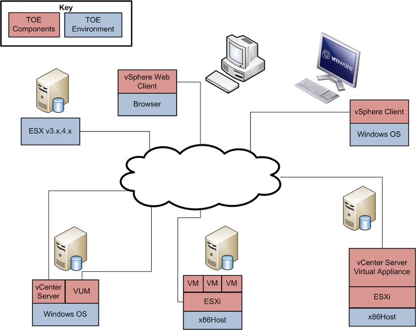
Figure 2 illustrates the physical scope and the physical boundary of the overall solution and ties together all
of the components of the TOE and the constituents of the TOE Environment. The TOE is software only
and the TOE Components are specified in Figure 2 below.
Figure 2 – Physical TOE Boundary
The acronym(s) appearing in Figure 2 and not previously defined are:
DB – Database
vCLI – vSphere Command Line Interface
VMware vSphere 5.1 Page 13 of 63
© 2012 VMware, Inc.
This document may be freely reproduced and distributed whole and intact including this copyright notice.Security Target, Version 0.7 April 19, 2012
Table 2 below indicates which elements of the product are included in the TOE boundary.
Table 2 – Components of the TOE
TOE
Component TOE
Environment
vCenter Server 5.0 Software
VMware Update Manager 5.0 Software (on the vCenter Server machine)
ESXi 5.0 Software
vSphere Client 5.0
vSphere Web Client 5.0
12
NTP Client on vSphere Client
NTP Client on ESXi host
NTP Server available to ESXi host and vCenter Server
ESXi host hardware (processor and adapters)
Storage Area Network hardware and software to be used with ESXi host
vCenter Server Hardware, operating system, and database.
vSphere Client hardware and operating system
vSphere Web Client hardware and operating system
Operating systems and applications running in VMs
Hardware, OS, and software (as identified in the previous sections) for remote
workstations
1.5.1.1 Guidance Documentation
The following guides are required reading and part of the TOE:
vSphere Availability Guide ESXi 5.0, ESXi 5.0, vCenter Server 5.0
vSphere Datacenter Administration Guide ESXi 5.0, ESXi 5.0, vCenter Server 5.0
ESXi Configuration Guide ESXi 5.0, vCenter Server 5.0
Fibre Channel SAN Configuration Guide ESXi 5.0, ESXi 5.0, vCenter Server 5.0
Getting Started with ESXi Installable ESXi 5.0 Installable, vCenter Server 5.0
Getting Started with ESXi Embedded ESXi 5.0 Embedded and vCenter Server 5.0
Introduction to VMware vSphere ESXi 5.0, ESXi 5.0, vCenter Server 5.0
iSCSI13 SAN Configuration Guide ESXi 5.0, ESXi 5.0, vCenter 5.0
vSphere Resource Management Guide ESXi 5.0, ESXi 5.0, vCenter Server 5.0
Setup for Failover Clustering and Microsoft Cluster Service ESXi 5.0, ESXi 5.0, vCenter Server
5.0
vSphere Upgrade Guide ESXi 5.0, ESXi 5.0, vCenter Server 5.0, vSphere Client 5.0
VMware, Inc. vSphere 5.0 Guidance Documentation Supplement
1.5.2 Logical Scope
The security functional requirements implemented by the TOE are usefully grouped under the following
Security Function Classes:
12
NTP – Network Time Protocol
13
iSCSI – Internet Small Computer System Configuration
VMware vSphere 5.1 Page 14 of 63
© 2012 VMware, Inc.
This document may be freely reproduced and distributed whole and intact including this copyright notice.Security Target, Version 0.7 April 19, 2012
Security Audit
Alarm Generation
Cryptographic Support
User Data Protection
Identification and Authentication
Security Management
Protection of the TOE Security Functions (TSF)
Virtual Machine Domain Separation
TOE Access
1.5.2.1 Security Audit
The auditing security function of the TOE is provided by both the ESXi and the vCenter Server. Audit data
collected by ESXi is stored in a flat file on the ESXi host. Audit data collected by the vCenter Server is
stored as events in the vCenter Server Database. Each audit record generated includes the date and time of
the event, the type of event, the subject identity (if applicable), and the outcome (success or failure) of the
event. The identity of the virtual machine, the scheduled task, or alarm identity is also recorded, if
applicable.
The vCenter Server provides the capability to review vCenter Server generated audit records by reviewing
the event logs stored on the vCenter Server Database. Only a vCenter Server Administrator can view all of
the event logs. Audit events are viewed through the vSphere Client under the event tab for each
organizational object. Audit events are viewed through the vSphere Web Client. ESXi provides the same
capability, using the syslog command to review its audit records which are stored in /var/log/messages.
Reviewing the audit records on ESXi is restricted to the ESXi System Administrator.
The vCenter Syslog Collector provides for centralized logging management of the ESXi hosts. The
vCenter Syslog Collector provides a unified architecture for system logging and enables network logging
and combining of logs from multiple hosts. The vCenter Syslog Collector is deployed on a protected
network so that the data-in-transit when ESXi logs are sent to the vCenter Syslog Collector host are
protected by the IT Environment.
1.5.2.2 Alarm Generation
Alarms are notifications that occur in response to selected events, conditions, and states that occur with
objects managed by the vCenter Server. The vCenter Server is configured with a set of predefined alarms
that monitor clusters, hosts, datacenters, datastores, networks, and virtual machines 14. Each predefined
alarm monitors a specific object and applies it to all objects of that type. For example, by default, the Host
CPU Usage alarm is set automatically on each ESXi host in the inventory and triggers automatically when
any host’s CPU usage reaches the defined CPU value.
If the predefined vCenter Server alarms do not account for the condition, state or the event that needs to be
monitored, the TOE users can define custom alarms. The TOE users use the vSphere Client to create,
modify, and remove alarms or the vSphere Web Client to view and monitor alarms.
1.5.2.3 Cryptographic Support
The TOE protects the confidentiality and integrity of all data as it passes between the remote components
of the TOE, or from the TOE to another trusted IT product. The TOE achieves this by using OpenSSL and
OpenSSH which performs the encryption and the decryption of data that is being passed.
The TOE implements CAVP-validated cryptographic algorithms to handle all cryptographic functions for
the encryption and the decryption of data.
14
Refer to Table 22 for the description of these terms: Clusters, Datacenters, Datastores, Networks, and
Virtual Machines.
VMware vSphere 5.1 Page 15 of 63
© 2012 VMware, Inc.
This document may be freely reproduced and distributed whole and intact including this copyright notice.Security Target, Version 0.7 April 19, 2012
1.5.2.4 User Data Protection
ESXi has the ability for authorized administrators to specify the information flow control security
functional policy used to control the flow of user data across the ports of the device. The Virtual and
Distributed Switch Information Flow Control SFP15 includes the information flow control SFP for both the
virtual switch and distributed switch functionality. A virtual switch, vSwitch,works much like a physical
Ethernet switch. It detects which virtual machines are logically connected to any of its virtual ports and
uses that information to forward traffic to the correct virtual machines on the same host machine. A
vNetwork Distributed Switch functions as a single virtual switch across multiple associated hosts. This
allows virtual machines to maintain consistent network configuration as they migrate between multiple
hosts. The vSwitches and VNetwork Distributed Switches include functionality identical to that of a
hardware Ethernet switch, although the implementation is solely in software: the source and destination
identifiers of network data packets entering the vSwitch/VNetwork Distributed Switch via any of its virtual
interfaces (which can be connected either to physical network interfaces, virtual machine virtual network
interfaces, or other vSwitches/VNetwork Distributed Switches) are analyzed and the packet is delivered
only to the appropriate virtual interface – the vSwitch/VNetwork Distributed Switch will not deliver
packets to unintended virtual interfaces.
1.5.2.5 Identification and Authentication
When a user attempts to log into ESXi, a user name and password are requested before access is given.
These authentication credentials are compared with the authentication credentials stored on the ESXi host
in a shadow file, where the password is hashed using Secure Hash Algorithm-1 (SHA-1). In addition,
ESXi can participate in an Active Directory (AD) infrastructure and can use the credentials provided by
AD for authorization. If the authentication credentials are valid, access to the system is provided, with the
privileges appropriate to the role assigned to that user. If the credentials are not valid, the user is presented
with another chance to provide valid credentials. Failed and successful user login events are captured in
the system logs.
When a user attempts to log into the vCenter Server, the user is presented with a login screen which
requests the vCenter Server’s network name or IP16 address, the user name, and the user password. The
user information is passed to the underlying Windows operating system of the vCenter Server which
verifies the user identity and password. vCenter Server can also participate in an Active Directory
infrastructure and can use the credentials provided by AD for authorization. If the login is valid, the user at
the vSphere Client is presented with the vSphere Client interface denoting a successful login. If the login is
invalid, a message is displayed, and the login window remains available for the user to retry. If the login is
valid, the user at the vSphere Web Client is presented with the vSphere Web Client user interface denoting
a successful login. If the login is invalid, a message is displayed, and the login window remains available
for the user to retry. Failed and successful user login events are captured in the system logs for both the
vSphere Client and the vSphere Web Client.
When VMware Update Manager starts up, it authenticates with vCenter Server. VUM instructs ESXi to
scan for compliance against a pre-defined or custom created baseline and then installs a single image with a
selected group of patches to be applied. ESXi will only call the instructed VUM instance, thereby ensuring
that only the VUM instance that is installed with the TOE will be used to download updates and patches to
the ESXi host. Security Management
The TOE provides a set of commands for administrators to manage the security functions, configuration,
and other features of ESXi. The Security Management function specifies user roles with defined access for
the management of ESXi. The TOE ensures that the ability to modify user privileges on the vCenter Server
objects is restricted to a vCenter Server Administrator, or to an administrator-defined role explicitly given
the required permissions. The TOE also ensures that the ability to modify permissions of users on ESXi
objects is restricted to system administrators.
15
SFP = Security Function Policy
16
IP: Internet Protocol
VMware vSphere 5.1 Page 16 of 63
© 2012 VMware, Inc.
This document may be freely reproduced and distributed whole and intact including this copyright notice.Security Target, Version 0.7 April 19, 2012
Note that for purposes of this ST, Administrative users are considered to be the users of the TOE. VM
users (individuals who access the guest operating system and applications within a virtual machine) are
outside the scope of the TOE and are not discussed any further here.)
1.5.2.6 Security Management
Security management specifies how the ESXi manages several aspects of the TSF including TSF data and
security functions. TSF data includes configuration data of the TOE, audit data, and system data. For a
detailed listing of TSF data managed by the TOE see Table 13 of this ST. The TOE provides authorized
administrators with management consoles as described in section 1.4.1 to easily manage the security
functions and TSF data of the TOE.
VM administrators are administrators of one or more VMs on the ESXi host. VM administrators can access
the VMs by directly logging into the ESXi host or through the vCenter Server via the vpxuser account and
password. When logging in through the vCenter Server, the vCenter Server uses the vpxuser account and
password to gain access to the ESXi host and process the requests on behalf of the VM administrators.
The TOE supports a combination of access control as detailed in Table 13. Users, groups, roles, and
permissions are used to control who is allowed access to the vSphere managed objects and the specific
actions that are allowed. vCenter Server and ESXi hosts determine the level of access for the user based on
the permissions that are assigned to said user. The combination of user name, password, and permissions is
the mechanism by which vCenter Server and ESXi hosts authenticate a user for access and authorize the
user to perform activities.
The servers and hosts maintain lists of authorized users and the permissions assigned to each user.
Privileges define basic individual rights that are required to perform actions and read properties. ESXi
and vCenter Server use sets of privileges or roles to control which users or groups can access particular
vSphere objects.
ESXi and vCenter Server provide a set of pre-established roles and allow for roles to be defined by
administrators. The privileges and roles assigned on an ESXi host are separate from the privileges and
roles assigned on vCenter Server. Only the privileges and roles assigned through the vCenter Server
system are available to administrators managing a host through vCenter Server. Refer to Table 13 for a
detailed listing of operations that are performed per specific data and role.
The vCenter Server supports two categories of roles: vCenter Server Administrator and Administrator
defined roles. The vCenter Server Administrator is implemented by membership in the “administrators”
group of the underlying Windows OS for vCenter Server. Users log in using their username and password,
and are automatically assigned in this role by virtue of their membership in the administrators group. The
vCenter Server Virtual Appliance Administrator is implemented by the root account on POSIX.17
1.5.2.7 Protection of the TSF
The Protection of the TSF function provides the integrity and management of the mechanisms that provide
the TSF. Protection of the TOE from physical tampering is ensured by its environment. It is the
responsibility of the administrator to assure that physical connections made to the TOE remain intact and
unmodified. The TOE protects the confidentiality and integrity of all data as it is transmitted between the
remote components of the TOE, or from the TOE to another trusted IT product by using OpenSSL or
OpenSSH as follows:
17
vSphere Install Guide, section “Download and Deploy the VMware vCenter Server Appliance”
VMware vSphere 5.1 Page 17 of 63
© 2012 VMware, Inc.
This document may be freely reproduced and distributed whole and intact including this copyright notice.Security Target, Version 0.7 April 19, 2012
HTTP communications between VUM and the ISP Server, and between VUM and the ESXi, are
protected by signature verification.
Client USB redirect from the USB ports on the host machine to the VMs is secured by OpenSSL.
HTTPS is used between the vSphere Web Client and the vCenter Server.
SSH is used to secure the communications between the ESXi host and a SSH Client on the remote
client
OpenSSL is used to secure communications between the ESXi host and vCLI on the remote client.
ESXi logs sent to the Syslog Collector host are secured while in transit.
1.5.2.7.1 Virtual Machine Domain Separation
The virtual machine separation security function of the TOE is provided by the ESXi component. The
TOE ensures that each virtual machine is isolated from any other virtual machines co-existing on the ESXi.
This isolation is provided at the virtualization layer of the ESXi. The virtualization layer of the ESXi
ensures that virtual machines are unable to directly interact with other virtual machines yet still allow for
physical resources to be shared among the existing virtual machines.
The ESXi provides an idealized hardware environment and virtualization of underlying physical resources.
Each virtual machine runs its own operating system and applications: they cannot communicate to each
other in unauthorized ways.
1.5.2.8 TOE Access
The TOE Access function enables termination of a user's session after a period of inactivity. The TOE will
lock an interactive session after an authorized administrator-specified time period of user inactivity.
1.5.3 Product Physical/Logical Features and Functionality not
included in the TOE
Each virtual machine can have users who are individuals using a virtual machine’s guest operating system
and applications that reside on the virtualized hardware of the virtual machine that is instantiated on an
ESXi host. These users access the VM via a remote workstation called a Remote Console, using an
Internet Protocol (IP) address associated with the specific virtual machine. The VMs themselves, their
operating systems, applications, and users are outside the scope of the TOE. The claims of the TOE are
relevant to the management, separation, isolation, and protection of the virtual machine structures, and not
of the functionality and actions that take place within a VM, and as such do not address the security issues
within each VM.
The following features of the system were not included in the evaluation.
Simple Network Management Protocol (SNMP), File Transfer Protocol (FTP), Telnet
The use of any authentication method on ESXi other than the local password database
VMware Software Development Kit (SDK) tools
The procfs interface on the ESXi host Service Console
VMware Scripting Application Programming Interface (API) on the ESXi host
VMware Consolidated Backup
Guest OS patch updates via Update Manager
VMware vSphere 5.1 Page 18 of 63
© 2012 VMware, Inc.
This document may be freely reproduced and distributed whole and intact including this copyright notice.You can also read