Installation and operating instructions - TOUCH800 - HERBERT DAMMANN ...
←
→
Page content transcription
If your browser does not render page correctly, please read the page content below
Installation and operating instructions

                        TOUCH800®

Version: V9.20191001

30322538-02-EN                Read and follow these instructions. Keep these instructions in a
                              safe place for later reference. Please note that there might be a
                              more recent version of these instructions on the homepage.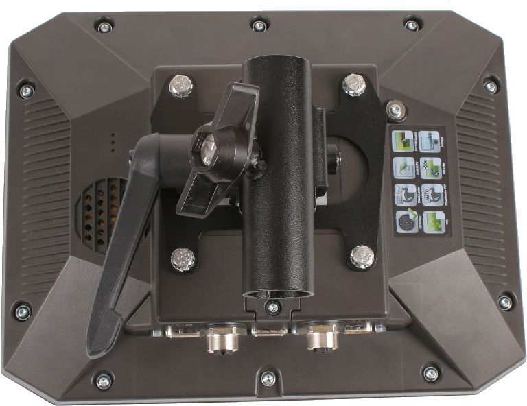
Company details
Document          Installation and operating instructions
                  Product: TOUCH800®
                  Document number: 30322538-02-EN
                  As of software version: 02.20.17
                  Original instructions
                  Original language: German

Copyright ©       Müller-Elektronik GmbH
                  Franz-Kleine-Straße 18
                  33154 Salzkotten
                  Germany
                  Phone: ++49 (0) 5258 / 9834 - 0
                  Fax: ++49 (0) 5258 / 9834 - 90
                  Email: info@mueller-elektronik.de
                  Homepage: http://www.mueller-elektronik.de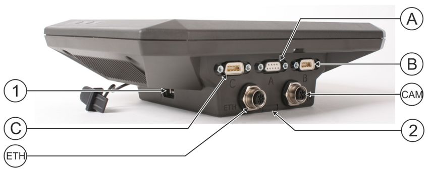
Table of contents

Table of contents
1        For your safety                                                                       7
1.1      Basic safety instructions                                                             7
1.2      Intended use                                                                          7
1.3      Layout and meaning of warnings                                                        8
1.4      Disposal                                                                              8
1.5      Instructions on retrofitting                                                          8
1.6      EU declaration of conformity                                                          9

2        About these Operating Instructions                                                10
2.1      Target group of these Operating Instructions                                      10
2.2      Layout of operating instructions                                                  10
2.3      Layout of references                                                              10
2.4      Directional information in these instructions                                     10

3        Product description                                                               11
3.1      Scope of delivery                                                                 11
3.2      Terminal buttons                                                                  11
3.3      Terminal ports                                                                    11
3.4      Applications on the terminal                                                      12
3.5      Information on the rating plate                                                   14

4        Mounting and installation                                                         15
4.1      Mounting the terminal in the vehicle cab                                          15
4.1.1        Mounting the standard bracket                                                 15
4.1.2        Mounting the optional bracket                                                 16
4.1.3        Mounting the optional adapter                                                 16
4.2      Connecting the terminal to the ISOBUS                                             17
4.3      Inserting micro-SD card                                                           18
4.4      Using two terminals                                                               18

5        Basic control principles                                                          19
5.1      Switching on the terminal                                                         19
5.2      Initial start-up                                                                  19
5.2.1        Using the terminal for parallel driving                                       19
5.2.2        Operating ISOBUS implement                                                    20
5.2.3        Terminal for automatic section control                                        20
5.2.4        Terminal for task management                                                  21
5.3      Switching off the terminal                                                        22
5.4      Terminal screen layout                                                            22
5.5      Opening applications                                                              23
5.6      Moving an application                                                             24
5.7      Saving and loading window arrangements                                            24

30322538-02-EN                                           V9.20191001                       3
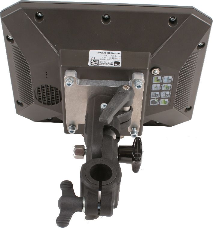
Table of contents

5.8        Hiding an application                                                                25
5.9        Using the keyboard                                                                   25
5.10       Using a memory device                                                                26
5.10.1         Using SD card                                                                    26
5.10.2         Folders on the USB memory device                                                 26
5.10.3         Displaying the content of the memory device on the terminal                      27

6          Connecting and configuring external devices                                          28
6.1        GPS receiver                                                                         28
6.1.1          Connecting the GPS receiver to the terminal                                      28
6.1.2          Changing the driver for the GPS receiver                                         28
6.1.3          Configuring the GPS receiver                                                     30
               Parameters for the GPS receiver                                                  30
               RTK or L band licence for SMART-6L                                               33
               GSM modem for SMART-6L                                                           33
               Configuring the GPS receiver for the steering system                             34
6.1.4          Recording GPS position                                                           35
6.1.5          Configuring the “GPS TILT-Module” tilt module                                    36
6.2        Configuring the joystick button allocations                                          36
6.3        Connecting sensors to the terminal                                                   37
6.4        Camera                                                                               38
6.4.1          Connecting the camera to the terminal                                            38
               Connecting the camera HQ2                                                        38
               Connecting the camera NQ                                                         39
6.4.2          Activating a camera                                                              39
6.4.3          Operating the camera                                                             40
6.5        External lightbar                                                                    40
6.5.1          Connecting the external lightbar to the terminal                                 40
6.5.2          Activating an external lightbar                                                  41
6.6        Connecting the on-board integrated display/controller to the terminal                41
6.7        ISO Printer                                                                          42
6.7.1          Connecting the ISO printer to the terminal                                       42
6.7.2          Activating ISO Printer                                                           43
6.8        Configuring the Bluetooth connection in the Connection Center                        43
6.9        Crop protection sensors                                                              43

7          Configuring the terminal in the Service application                                  45
7.1        Changing the language                                                                45
7.2        Basic terminal settings                                                              45
7.3        Activating and deactivating applications                                             47
7.4        Unlocking licenses for full versions                                                 48
7.5        Creating screenshots                                                                 49
7.6        Deleting pools                                                                       49
7.7        Using the Open Data Interface                                                        49
7.7.1          Activating ME ODI                                                                50
7.7.2          Opening ME ODI                                                                   50

4                                                           V9.20191001            30322538-02-EN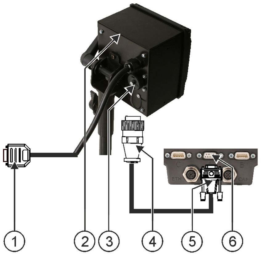
Table of contents
8 Tractor-ECU application 51
8.1 Work screen 51
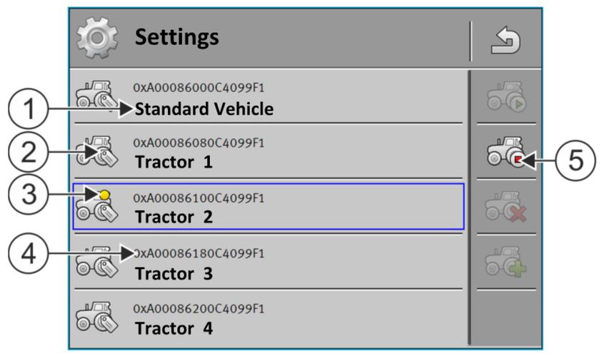
8.2 Managing the tractor profiles 51
8.3 Parameter 53
8.3.1 Calibrating the speed sensor 55
8.3.2 Calibrating an analog work position sensor 56
8.3.3 Tractor geometry 56
Configuring the tractor connector types 57
Configuring the tractor geometry 58
8.4 Results 59
8.4.1 Trip counter 59
8.4.2 Task-related counter 59
9 Virtual ECU application 61
9.1 Managing virtual job computers 61
9.2 Parameter 62
9.3 Work screen 65
10 Task management (ISOBUS-TC) 66
10.1 Configuring ISOBUS-TC 66
10.1.1 The “farmpilot” parameter 66
10.1.2 “Operating Mode” parameter 66
10.1.3 “TC number” parameter 67
10.1.4 “Prefer internal Tractor-ECU?” parameter 67
10.1.5 “Save finished tasks as a file?” parameter 67
10.1.6 “Validation of the device description” parameter 67
10.1.7 “Simplified target rate assignment?” parameter 68
10.2 Configuring the list of connections 68
10.3 Using fields and shp data 69
10.3.1 What is field data for? 70
10.3.2 Creating fields 70
10.3.3 Activating and deactivating fields 71
10.3.4 Importing field data (*.shp) 72
10.3.5 Exporting field data 72
10.3.6 Data on the memory device 73
10.3.7 Transferring field data to a different terminal 73
10.4 Using prescription maps 73
10.4.1 Importing shape prescription maps 74
10.4.2 Selecting shape prescription maps 75
10.4.3 Editing shape prescription maps 75
10.4.4 ISO-XML prescription maps 76
10.5 MULTI-Control 76
11 FILE-Server application 78
12 Technical specifications 79
12.1 Technical specifications of the terminal 79
30322538-02-EN V9.20191001 5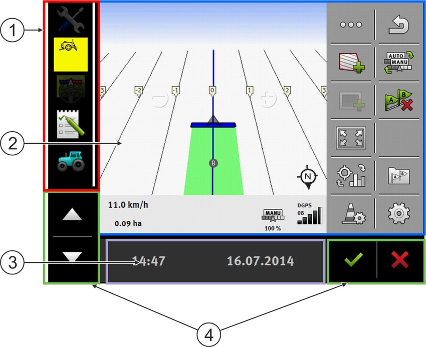
Table of contents

12.2       Pin-out diagrams                                     80
12.2.1         Port A (CAN bus)                                 80
12.2.2         Port B                                           80
12.2.3         Port C                                           81
12.2.4         CAM port                                         82
12.2.5         ETH (Ethernet) port                              83
12.3       Licence conditions                                   83

13         Troubleshooting                                      84

6                                    V9.20191001   30322538-02-EN
For your safety

                                                                                             Basic safety instructions   1

1            For your safety

1.1                  Basic safety instructions
                     Please read the following safety instructions carefully before using the product for the first time.
                       ▪ Do not operate the terminal while driving in road traffic. Come to a standstill in order to use the
                         unit.
                       ▪ Before maintenance or repair to the tractor, always disconnect the connection between the
                         tractor and the terminal.
                       ▪ Before charging the tractor battery, always disconnect the connection between the tractor and
                         the terminal.
                       ▪ Before welding on the tractor or implement, always disconnect the power supply to the terminal.
                       ▪ Do not make any unauthorized modifications to the product. Unauthorized modifications or use
                         may impair safety and reduce the service life or operability of the unit. Modifications are
                         considered unauthorized if they are not described in the product documentation.
                       ▪ Follow all recognised safety, industrial and medical rules as well as all road traffic laws.
                       ▪ The product does not include any user-serviceable parts. Do not open the casing. If the casing is
                         opened, its imperviousness can be changed.
                       ▪ Read the operating instructions to the agricultural device which you want to control by using the
                         product.

                     Using a camera
                     The camera serves solely for observing the implement functions in non-safety-related working areas
                     of the agricultural implement.
                     In certain situations, the camera image may appear on the screen with a delay. The delay depends
                     on the respective use of the terminal and can also be affected by external factors and devices.
                     For this reason, please note the following information:
                      ▪ Do not use the camera to assist with steering the vehicle: not in road traffic, and not on private
                          properties.
                      ▪ Do not use the camera to watch the road traffic or when driving into intersections.
                      ▪ Do not use the camera as a rear view camera.
                      ▪ Do not use the camera as a visual aid for controlling the implement, especially when a delayed
                          reaction can lead to risks.
                      ▪ Using a camera does not exempt you from your due diligence obligation to pay attention to
                          safety when operating the implement.

1.2                  Intended use
                     The terminal is used to operate implements equipped with ISOBUS job computers.
                     Intended use also includes compliance with the conditions for operation and repairs prescribed by the
                     manufacturer.
                     The manufacturer cannot be held liable for any personal injury or property damage resulting from
                     such non-compliance. All risk arising from improper use lies with the user.
                     All applicable accident prevention regulations and all other generally recognized safety, industrial,
                     and medical standards as well as all road traffic laws must be observed. Any unauthorized
                     modifications made to the equipment will void the manufacturer's warranty.

30322538-02-EN                                    V9.20191001                                                                7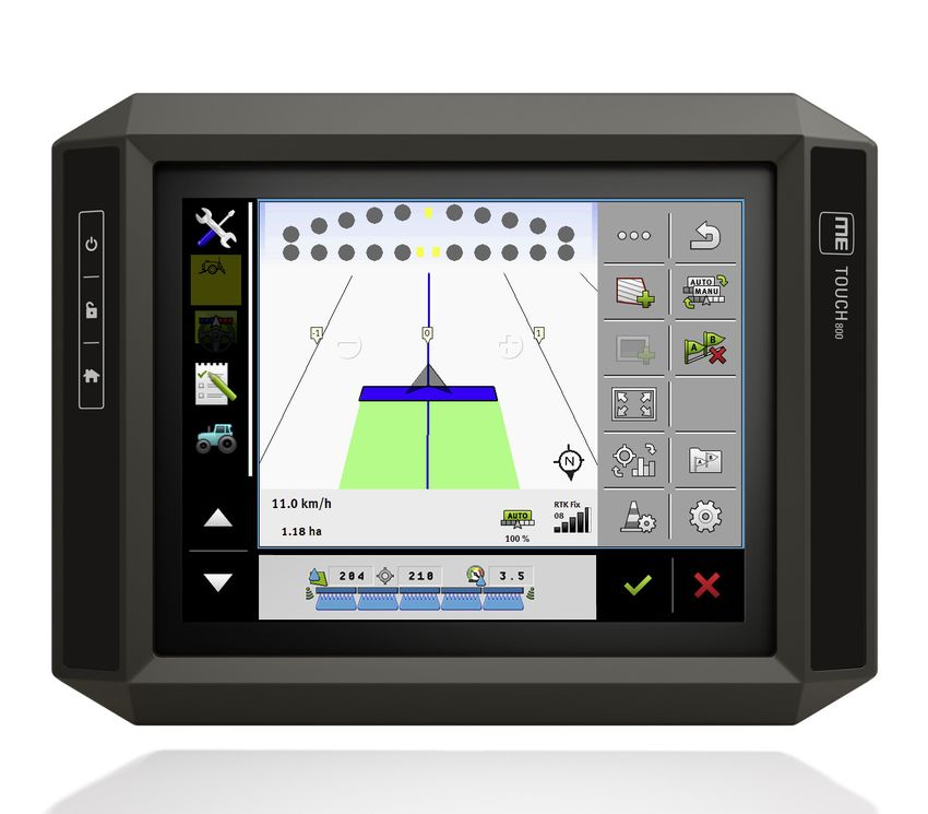
For your safety
    1     Layout and meaning of warnings

1.3                             Layout and meaning of warnings
                                All safety instructions found in these Operating Instructions are composed in accordance with the
                                following pattern:

                                           WARNING
                                 This signal word identifies medium-risk hazards, which could potentially cause death or serious
                                 physical injury, if not avoided.

                                           CAUTION
                                 This signal word identifies hazards that could potentially cause minor or moderate physical injury or
                                 damage to property, if not avoided.

                                 NOTICE
                                 This signal word identifies hazards that could potentially cause damage to property, if not avoided.

                                There are some actions that need to be performed in several steps. If there is a risk involved in
                                carrying out any of these steps, a safety warning appears in the instructions themselves.
                                Safety instructions always directly precede the step involving risk and can be identified by their bold
                                font type and a signal word.

Example                          1. NOTICE! This is a notice. It warns that there is a risk involved in the next step.
                                 2. Step involving risk.

1.4                             Disposal
                                              When it has reached the end of its service life, please dispose of this product as
                                              electronic scrap in accordance with all applicable waste management laws.

1.5                             Instructions on retrofitting

                                Instructions on how to retrofit electrical and electronic farm equipment and/or
                                components
                                Agricultural equipment used today features electronic components and parts whose function can be
                                affected by other farm equipment which emits electromagnetic waves. Such effects could lead to
                                personnel being put in danger, if the following safety instructions are not adhered to.

Selecting components            When selecting components, make sure first of all that the retrofitted electrical and electronic
                                components comply with the current version of the EMC Directive 2004/108/EC and carry the CE
                                marking.

8                                                            V9.20191001                                               30322538-02-EN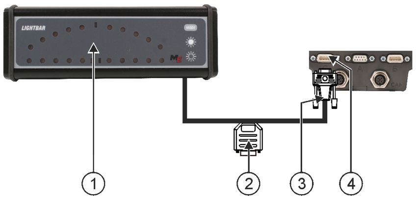
For your safety

                                                                                              EU declaration of conformity   1

User responsibility       When retrofitting a machine with electrical and electronic farm equipment and/or components
                          connected to the vehicle's electrical system, it is your own responsibility to check whether the
                          installation causes interference with the vehicle's electronic system or other components. This
                          applies, in particular, to the electronic control of:
                            ▪ electronic hitch control (EHR),
                            ▪ Front lifting gear,
                            ▪ PTO shafts,
                            ▪ Motor,
                            ▪ Gear.

Additional requirements   The following requirements must be met in order to retrofit mobile communication systems (e.g. radio,
                          phone):
                           ▪ Only approved devices complying to national regulations (e.g. BZT approval in Germany) are to
                              be installed;
                           ▪ The equipment must be installed as a fixed installation.
                           ▪ The use of portable or mobile devices inside the vehicle is permissible only via a connection to
                              the permanently installed outside antenna;
                           ▪ The transmitting part must be spatially separated from the vehicle's electronic system.
                           ▪ When attaching the antenna, pay attention to proper installation, including a sound ground
                              connection between the antenna and the vehicle's ground wire.
                          For information on wiring and installation as well as the maximum allowable current consumption,
                          please also refer to the installation guide provided by the machine manufacturer.

1.6                       EU declaration of conformity
                          Herewith we declare that the design and construction of this product and its identical variants, as well
                          as the form brought onto the market by us, is in accordance with the relevant safety and health
                          requirements of the EU Directive of Electromagnetic Compatibility 2014/30/EU. If alterations are
                          made to the product without prior consultations with us, this declaration becomes invalid.
                          TOUCH800®

                          Harmonised standards applied:                        EN ISO 14982:2009
                                                                               (EMC Directive 2014/30/EU)

30322538-02-EN                                         V9.20191001                                                               9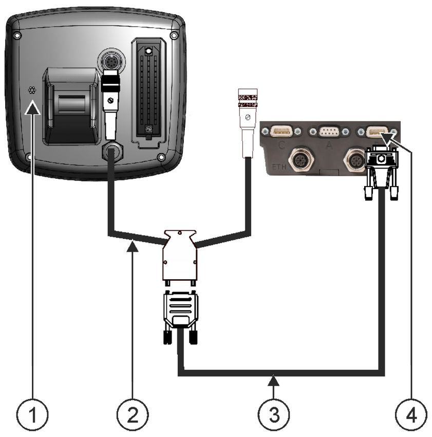
About these Operating Instructions
     2   Target group of these Operating Instructions

2              About these Operating Instructions

2.1                              Target group of these Operating Instructions
                                 These Operating Instructions are intended for personnel entrusted with installing and operating the
                                 terminal.

2.2                              Layout of operating instructions
                                 The operating instructions explain step by step how you can perform certain operations with the
                                 product.
                                 We use the following symbols throughout these Operating Instructions to identify different operating
                                 instructions:

                                 Type of depiction                                        Meaning

                                 1.                                                       Actions that must be performed in succession.
                                 2.

                                 ⇨                                                        Result of the action.
                                                                                          This will happen when you perform an action.

                                 ⇨                                                        Result of an operating instruction.
                                                                                          This will happen when you have completed all
                                                                                          steps.

                                                                                          Requirements.
                                                                                          In the event that any requirements have been
                                                                                          specified, these must be met before an action
                                                                                          can be performed.

2.3                              Layout of references
                                 If any references are given in these Operating Instructions, they appear as:
                                 Example of a reference: [➙ 10]

                                 References can be identified by their square brackets and an arrow. The number following the arrow
                                 shows you on what page the section starts where you can find further information.

2.4                              Directional information in these instructions
                                 All directional information in these instructions, such as “left”, “right”, “forward”, “back”, is relative to
                                 the movement direction of the vehicle.

10                                                              V9.20191001                                                   30322538-02-EN
Product description
Scope of delivery 3
3 Product description
3.1 Scope of delivery
The following items are included in delivery:
▪ TOUCH800 terminal
▪ VESA holder and screws
▪ Bracket for mounting the terminal
▪ USB memory device
▪ Installation and Operating Instructions
▪ Operating instructions for the ISOBUS-TC application - as a separate document.
3.2 Terminal buttons
You will find a number of buttons on the housing of the terminal that are used to operate the terminal.
Terminal buttons
Function of the buttons
Switches the terminal on and off.
Creates screenshots.
Saves the window layout.
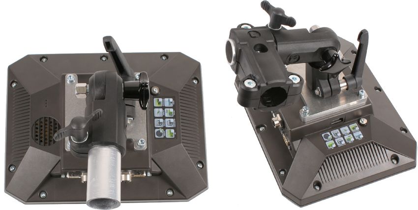
3.3 Terminal ports
Terminal ports
30322538-02-EN V9.20191001 11Product description
3 Applications on the terminal
USB port for: Port A
- USB memory device [➙ 26] CAN bus port for:
- ISOBUS basic vehicle harness [➙ 17]
- Connection to the tractor CAN bus
Port C Port B
Serial port for: See section: Pin assignment connector B [➙
- GPS receiver [➙ 28] 80]
- GPS TILT-Module
- Lightbar [➙ 40]
ETH port CAM port
M12 port for: Port for an analog camera
- Ethernet
Slot with the SD card
3.4 Applications on the terminal
The terminal is delivered with a range of installed application (apps). Most of these can be used
immediately. Even the non-activated applications can generally be tested for 50 hours. If a specific
application works well for you, a license can be ordered from Müller-Elektronik to activate the full
version of the application.
Full versions The full versions of the following applications are installed on the terminal:
▪ ISOBUS interface (ISOBUS-UT)
The terminal enables you to operate ISOBUS job computers which are ISO 11783 compliant.
The user interfaces for operating a job computer are shown on the terminal screen if this is
connected to the ISOBUS connector of the vehicle.
The ISOBUS interface has no icon of its own. The icon for the connected job computer will
always be displayed in the selection menu.
▪ - Service application.
The Service application allows you to:
– Configure the terminal.
– Enable and disable other applications.
– Enter license activation codes.
– Enable drivers for connected devices.
– Configuration of the GPS settings
▪ - Tractor-ECU application
The Tractor-ECU application is used to record all settings around the tractor.
Here, you can e.g.:
– Enter the position of the GPS receiver.
– Set the GPS receiver as the speed signal source.
– Select which sensor signals are received by the terminal.
– View the speed and PTO shaft rotational speed on the screen.
More about this in section: Tractor-ECU application [➙ 51]
12 V9.20191001 30322538-02-ENProduct description
Applications on the terminal 3
▪ - Virtual ECU application
The Virtual ECU application is a central hub where virtual job computers can be created for
machines and devices that do not communicate through ISOBUS.
The Virtual ECU enables the use of apps such as TRACK-Leader, ISOBUS-TC and SECTION-
Control with non-ISO machines.
More about this in section: Virtual ECU application [➙ 61]
▪ FILE-Server application
This application is used to define a storage location on the terminal. This storage location can be
used by ISOBUS job computers that support the FILE-Server functionality. The options for use
depend on the ISOBUS job computer.
▪ - Camera
The Camera application displays on the screen the image from the camera which is connected
to the terminal.
Test versions You can use the test versions of the following applications:
▪ - TRACK-Leader application.
The TRACK-Leader application allows you to work the field on exact parallel tracks.
The app contains several modules for which a license can also be activated:
– SECTION-Control: Automatic section control in order to minimize overlaps.
– TRACK-Leader AUTO: Automatic vehicle steering on the field.
– TRACK-Leader AUTO CLAAS: Automatic vehicle steering on the field for CLAAS tractors.
– TRACK-Leader TOP: Automatic vehicle steering on the field.
– TRAMLINE-Management: Tramline control using the current GPS position.
▪ - ISOBUS-TC application (ISOBUS task controller)
The ISOBUS-TC application serves as an interface between the terminal applications
(SECTION-Control, TECU, VECU) and ISOBUS devices (job computers, crop protection
sensors). Moreover, the app enables data transfer between the terminal and electronic Farm
Management Information Systems.
The scope of functions depends on the activated licenses and the configuration.
More about this in section: Task management (ISOBUS-TC) [➙ 66]
▪ MULTI-Control – This license extends the functionality of ISOBUS-TC. It enables the assignment
of prescription maps to individual metering units on a machine.
▪ ASD protocol – The license enables communication between the terminal and a serially
connected on-board integrated display/controller. The terminal knows the position of the machine
on the field (GPS) and can transmit the target application rate of a product (from the prescription
map) or the section status to the on-board integrated display/controller. In this way, you can use
the SECTION-Control app for section control, among other things.
More about this in section: Connecting the on-board integrated display/controller to the terminal [
➙ 41]
▪ ME ODI – This license activates the ME ODI application. It is used to connect the terminal with
the Internet via Ethernet or Bluetooth.
Optional software Optionally you can activate the following software:
▪ - FIELD-Nav application
30322538-02-EN V9.20191001 13Product description
3 Information on the rating plate
FIELD-Nav – Road navigation for agricultural purposes. The map material can be edited with the
corresponding PC software FIELD-Nav Desktop. All field tracks, small bridges and other
restrictions can then be integrated in the map material and be considered when mapping the
route.
You will find the operating instructions on the Müller-Elektronik website.
▪ - Agricon plugin
Enables coupling with crop protection sensors (Yara-N, P3US, P3ALS etc.) manufactured by
Agricon.
3.5 Information on the rating plate
You will find a nameplate sticker on the back of the terminal. On this sticker, you can find all the
information you need to definitively identify the product.
Have these details ready when you contact Customer Services.
Abbreviations on the rating plate
Abbreviation Meaning
Software version
You can see the installed software version on the Start Screen of the
Service application:
Hardware version
Operating voltage
The terminal may only be connected to voltages within this range.
Customer number
If the terminal was manufactured for an agricultural machinery
manufacturer, the agricultural machinery manufacturer's item number
will be shown here.
Serial number
14 V9.20191001 30322538-02-ENMounting and installation
Mounting the terminal in the vehicle cab 4
4 Mounting and installation
4.1 Mounting the terminal in the vehicle cab
You need a bracket to mount the terminal in the vehicle cab. The following brackets are available.
Item number Type Scope of Properties
delivery?
31322506 Standard bracket Yes
▪ For a more sturdy attachment of the
31322507 Optional bracket No
terminal.
▪ Is mounted on bracket 31322507.
31322508 Optional adapter No
▪ Suitable for vehicles without a B
column.
▪ Is mounted around a pipe.
4.1.1 Mounting the standard bracket
Procedure You have the VESA bracket assembly kit within reach.
1. Assemble the bracket together.
2. Secure the bracket with the four screws on the back side of the terminal.
3. Secure the terminal in the vehicle cab. You can, for example, use the ME mounting bracket for
this purpose. It is included in the scope of delivery of the ISOBUS basic vehicle harness.
⇨ Your terminal should be mounted as follows:
4. Check that your terminal is firmly mounted.
⇨ You can now connect cables to the terminal. [➙ 11]
30322538-02-EN V9.20191001 15Mounting and installation
4 Mounting the terminal in the vehicle cab
4.1.2 Mounting the optional bracket
Procedure You have the bracket assembly kit within reach.
1. Assemble the bracket together.
2. Secure the bracket with the four screws on the back side of the terminal.
3. Put the bracket into the desired position. For example:
4. Secure the terminal in the vehicle cab. You can, for example, use the ME mounting bracket for
this purpose. It is included in the scope of delivery of the ISOBUS basic vehicle harness.
5. Check that your terminal is firmly mounted.
4.1.3 Mounting the optional adapter
If you want to mount your terminal in a vehicle that does not have a B column, you can install an
adapter onto bracket 31322507. This adapter can be mounted around a pipe.
16 V9.20191001 30322538-02-ENMounting and installation
Connecting the terminal to the ISOBUS 4
▪ Adapter for round pipe systems, for pipes with a diameter of 20, 25 or 30 mm, item number:
31322508
Procedure 1. Assemble the adapter together.
2. Connect the adapter with the bracket.
3. Put the bracket and the adapter in the desired position.
4. Check that everything is firmly mounted.
4.2 Connecting the terminal to the ISOBUS
Connection to the ISOBUS serves to:
▪ supply the terminal with power,
▪ enable communication with other ISOBUS components.
You will need a different connection cable for this, depending on the model of your tractor.
▪ In tractors that have been retroactively upgraded with an ISOBUS basic vehicle harness
manufactured by Müller-Elektronik, use connector cable A from the ISOBUS basic vehicle
harness.
▪ In tractors that are equipped as standard with ISOBUS and that have an ISOBUS in-cab
connector, you will need the following connector cable:
Connector cable D-Sub CPC Item no. 30322541
30322538-02-EN V9.20191001 17Mounting and installation
4 Inserting micro-SD card
When there is more than one terminal in the tractor cab, you may need to change certain settings in
order to enable two-way communication. Find out more: Using two terminals [➙ 18]
Procedure 1. Connect the 9-pin connector A of the basic vehicle harness to the CAN port of the terminal.
2. Tighten the safety screws on the connector.
4.3 Inserting micro-SD card
The micro-SD card serves as internal storage for the terminal.
Procedure To change the SD card:
1. Switch off the terminal and disconnect all cable connections.
2. Unscrew the cover on the rear of the terminal.
3. Use your finger to press on the SD card in the slot.
⇨ The SD card is unlocked and now protrudes by approx. 1 mm.
4. You can remove the card.
5. To lock the card again, press the card lightly into the slot until it is locked again.
6. Screw the cover back onto the rear of the terminal.
4.4 Using two terminals
The following table will tell you which settings you need to configure to be able to use two terminals,
and the sections in which these are described. The specifications on the in-cab terminals are without
liability.
Settings for the ME terminal and in-cab terminal
Possible purpose Setting of the ME terminal Setting of the in-cab terminal
TRACK-Leader and SECTION-Control on Login as ISOBUS terminal: No [➙ 45] Activate the ISOBUS terminal (JohnDeere:
the ME terminal. Implement Bus; Fendt: Fendt ISOBUS
terminal).
Operation of the job computer on the in-
cab terminal. Deactivate Task Controller (JohnDeere:
Task Controller; Fendt: Taskcontroller).
TRACK-Leader, SECTION-Control, and Login as ISOBUS terminal: Yes [➙ 45] Deactivate the ISOBUS terminal
job computer operation on the ME (JohnDeere: Implement Bus; Fendt: Fendt
terminal. ISOBUS terminal).
Deactivate Task Controller (JohnDeere:
Task Controller; Fendt: Taskcontroller).
For JohnDeere, also deactivate:
Greenstar, Original Greenstar
18 V9.20191001 30322538-02-ENBasic control principles
Switching on the terminal 5
5 Basic control principles
5.1 Switching on the terminal
Procedure To switch on the terminal:
The terminal is installed and connected to the ISOBUS basic vehicle harness.
1. Press and hold the button for approx. 3 seconds.
⇨ The terminal will beep briefly.
⇨ The terminal screen remains dark for approx. 10 seconds until the applications are loaded in
the background.
⇨ The Start screen of the terminal appears:
⇨ You have started the terminal.
5.2 Initial start-up
The next step to perform after switching on the terminal depends on the purpose of the terminal:
▪ Parallel driving
▪ Operation of ISOBUS implements
▪ Automatic section control
▪ Task management and documentation
These cases will be described in the following sections.
5.2.1 Using the terminal for parallel driving
If you want to use the terminal for parallel driving, TRACK-Leader is the most important app for you.
Most important settings
Setting Where? Purpose
Select the GPS driver. The standard driver works in
/ Driver / GPS [➙ 28] most cases for the receivers
sold by ME. However, to
change the correction signal, a
fitting driver for the GPS
receiver must be activated.
30322538-02-EN V9.20191001 19Basic control principles
5 Initial start-up
Setting Where? Purpose
Enter the tractor geometry and See:
activate the tractor profile. / Settings
- Managing the tractor profiles [
➙ 51]
- Tractor geometry [➙ 56]
Virtual job computer For the system to be able to
/ Settings know the working width and
other parameters of the
machine, you must create a
virtual job computer for every
non-ISOBUS-compatible
machine that you use.
See: Virtual ECU application [
➙ 61]
Other settings must be made in the TRACK-Leader application.
5.2.2 Operating ISOBUS implement
To operate an ISOBUS job computer with the terminal, it is sufficient to connect the job computer to
the rear ISOBUS socket. As a standard, the terminal disposes of the required licences.
Procedure The “ISOBUS-UT” licence is activated.
1. Insert the ISOBUS cable of the job computer into the ISOBUS rear socket.
2. Switch on the terminal.
3. Wait until the job computer application has copied all of the relevant data on the terminal.
4. Open the job computer application using the selection menu [➙ 23].
5.2.3 Terminal for automatic section control
Most important settings
Setting Where? Commentary
Select the GPS driver The standard driver works in
(optional). / Driver / GPS [➙ 28] most cases for the receivers
sold by ME. However, to
change the correction signal, a
fitting driver for the GPS
receiver must be activated.
Enter the tractor geometry and See:
activate the tractor profile. / Settings
- Managing the tractor profiles [
➙ 51]
- Tractor geometry [➙ 56]
20 V9.20191001 30322538-02-ENBasic control principles
Initial start-up 5
Setting Where? Commentary
Connecting the job computer to
the ISOBUS.
Job computer profile in Search for a profile and set the
SECTION-Control / Settings / SECTION- “Machine model” parameter.
Control
For more precise operation,
configure all of the other
parameters in the profile.
Procedure The “ISOBUS-UT”, “TRACK-Leader” and “SECTION-Control” licenses are activated.
1. Insert the ISOBUS cable into the ISOBUS rear socket.
2. Switch on the terminal.
3. Wait until the job computer application has copied all of the relevant data on the terminal.
4. - Open the TRACK-Leader application using the selection menu [➙ 23].
5. Configure the settings from the table above.
6. Start a new navigation.
You can read how to proceed in the operating instructions for TRACK-Leader.
5.2.4 Terminal for task management
You can always use ISOBUS-TC task management, regardless of whether you are driving in parallel,
switching sections or simply operating an ISOBUS job computer. However, the most important
settings mentioned in the previous sections must be made for each of these applications.
Important for ISOBUS-TC:
▪ Always remember to start and stop the tasks.
▪ After finishing work, you must save all of the tasks on the USB memory device (log out the USB
memory device) before you remove the USB memory device or transmit new tasks onto the
terminal.
Most important settings
Setting Where? Purpose
Set the operating mode to Activates and deactivates task
“Extended”. / Settings management in the ISOBUS-
TC application.
If you do not want to create
tasks, set the operating mode to
“Standard”.
Insert the USB memory device
with task data or create tasks
without a USB memory device.
Procedure The “ISOBUS-TC” licence is activated.
30322538-02-EN V9.20191001 21Basic control principles
5 Switching off the terminal
1. Switch on the terminal.
2. - Open the ISOBUS-TC application using the selection menu [➙ 23].
3. Insert a USB memory device with task data.
4. Start a task.
5.3 Switching off the terminal
Procedure To switch off the terminal:
1. Press and hold the button for approx. 3 seconds.
⇨ You have now switched off the terminal.
5.4 Terminal screen layout
Terminal screen layout
Selection menu Wide additional window
You can open applications in the “Selection
Menu” area.
Main window System icons
This area enables you to operate applications.
Touching the terminal screen in the “Main
window” area will actuate the function whose
icon you have touched.
The controls depend on the opened
applications.
System icons
Icon Meaning
Has no function in this area.
When this icon appears in other areas, it is used for confirmation
22 V9.20191001 30322538-02-ENBasic control principles
Opening applications 5
Icon Meaning
purposes.
Has no function in this area.
When this icon appears in other areas, it is used for cancellation or
deletion purposes.
Has no function in the current software version.
Has no function in the current software version.
5.5 Opening applications
An application opens when it appears in the main window or in an additional window.
Procedure To open an application:
1. Find the function icon for the desired application in the Selection menu area. For example, the
icon:
2. Tap the function icon of the application:
⇨ The application appears in the main window:
⇨ The function icon of the application in the Selection menu now appears darker. This tells
you that this application is already open. You will no longer be able to open it from the
Selection menu.
⇨ If the main window is occupied, the application that is already opened will be moved to a
free additional window. If this is occupied, the application that is already opened will be
moved back to the Selection menu. Their icon becomes bright again. However, it can
continue to work in the background.
30322538-02-EN V9.20191001 23Basic control principles
5 Moving an application
5.6 Moving an application
You can move any application from the main window to one of the additional windows or to the ME-
Header.
Procedure To move an application from the main window to an additional window:
You have opened an application in the main window. For example, the Service application:
1. Tap the additional window:
⇨ The application will now appear in the additional window:
2. Tap the additional window with the application.
⇨ The application will once again appear in the main window.
5.7 Saving and loading window arrangements
You can save and load the arrangement of the applications in the windows.
Procedure To save the arrangement:
1. Hold the button pressed down until the terminal beeps twice.
24 V9.20191001 30322538-02-ENBasic control principles
Hiding an application 5
⇨ The arrangement will be saved.
Procedure To load a saved arrangement:
1. Briefly press the button:
⇨ The arrangement will be loaded.
5.8 Hiding an application
If you do not have enough space on the terminal screen to open new applications, you can hide an
application. The application will not be shut down, but will instead continue to run in the background.
Procedure To hide an application:
1. Open the application in the additional window.
2. Move the application to the selection menu.
5.9 Using the keyboard
In order to enable you to also write numbers or text on the terminal, a keyboard appears on the
terminal screen whenever this is necessary.
Major icons
Icon Meaning
Changes the buttons on the keyboard.
12#
Abc
Deletes a character.
Moves the cursor.
Saves the input.
Cancels the input.
Switches between upper and lower case letters.
30322538-02-EN V9.20191001 25Basic control principles
5 Using a memory device
Keyboard for inputting text and numbers.
Keyboard for inputting text.
5.10 Using a memory device
The terminal can work with two kinds of memory devices:
1. With an integrated micro-SD card. This will be used as storage for most applications.
2. With an inserted USB memory device.
The USB memory device is used only for the following purposes:
▪ For data transfer [➙ 26] between the terminal and PC
▪ For saving screenshots
5.10.1 Using SD card
The terminal applications save most data [➙ 26] directly onto the SD card.
In order to exchange data between the terminal and a PC, you will need to proceed differently for
each application. You can find out more about this in the instructions for each application.
5.10.2 Folders on the USB memory device
As soon as you insert the USB memory device into the terminal, several folders will be created on the
USB memory device. You will need to set up other folders by yourself.
Each folder may only contain certain data, so that the applications on the terminal can use this data.
▪ “documents”
– Files: .txt
– Purpose: Records for all completed tasks are saved in this folder.
▪ “FIELDNav”
– Files: .iio, .data
– Purpose: Map material will be saved in this folder.
– The folder will be created when the FIELD-Nav license is activated.
26 V9.20191001 30322538-02-ENBasic control principles
Using a memory device 5
▪ “fileserver”
– Files: All file formats are acceptable.
– Purpose: Files which are to be imported or exported in the FILE-Server application are
saved in this folder.
▪ "GPS"
– Files: .txt
– Purpose: GPS positions are saved in a file in the folder. This will enable Customer Service
to reconstruct the traveled distance.
– The folder will be created if you activate the “Record and save data” parameter.
▪ “NgStore”
– Files: .iio, .data
– Purpose: TRACK-Leader. Standard folder for saved routes and fields.
▪ “Screencopy”
– Files: .bmp
– Purpose: Screenshots are saved here.
– The terminal will create this folder automatically when the “Screenshot” parameter is
activated in the “Terminal” menu and you create a screenshot.
▪ "SHP"
This folder replaces the “GIS” folder that was used in previous versions.
– Files: .dbf, .kml, .prj, .shp, .shx
– Purpose: TRACK-Leader: After saving with the SD card, the field data will be stored here.
For example: Field boundaries, applied areas, headlands, etc.
ISOBUS-TC: The shp files must be stored in this folder.
▪ “Taskdata”
– Files: .xml
– Purpose: The folder may only contain XML files which originate from an ISO-XML
compatible FMIS. The ISOBUS-TC application accesses this data.
– You must create this folder yourself.
5.10.3 Displaying the content of the memory device on the terminal
You can view the content of the memory device directly on the terminal.
Procedure 1. Insert the memory device (USB memory device or SD card) into the terminal.
2. Open the “Service” application.
3. Tap on “USB 1” or on “SDCard”.
⇨ The content of the USB memory device will be displayed.
⇨ The content of the SD card can be found in the “ME-TERMINAL” folder.
30322538-02-EN V9.20191001 27Connecting and configuring external devices
6 GPS receiver
6 Connecting and configuring external devices
6.1 GPS receiver
6.1.1 Connecting the GPS receiver to the terminal
Find out how to connect a GPS receiver from Müller-Elektronik to the terminal from the operating
instructions for the GPS receiver.
When mounting the terminal in a vehicle which is already fitted with a GPS receiver and another
ISOBUS terminal, you must:
▪ connect the GPS signal to the terminal manufactured by Müller-Elektronik.
▪ configure the GPS receiver.
Procedure To connect the terminal to a GPS receiver which is already installed on the vehicle:
1. Find out how you can direct the signal from the GPS receiver to the terminal. This can differ for
every vehicle or GPS receiver: Vehicles can be fitted with a GPS socket in the cab, a GPS
receiver with a serial output or serial outputs to the ISOBUS terminal.
2. Check what cable you will use to connect GPS signal to the serial socket on the terminal
manufactured by Müller-Elektronik.
3. Connect the GPS signal to the serial socket of the terminal manufactured by Müller-Elektronik.
4. Configure the GPS receiver so that it can communicate with the terminal manufactured by
Müller-Elektronik. You can find the necessary specifications for this in the table below.
5. Activate the “Standard” GPS driver on the terminal.
Configuration
Frequencies 5 Hz (GPGGA, GPVTG)
1 Hz (GPGSA, GPZDA)
Transmission rate 19200 baud
Data bits 8
Parity No
Stop bits 1
Flow control None
6.1.2 Changing the driver for the GPS receiver
Upon delivery, the “Standard” driver is activated on the terminal. You must change this driver if you
want to reconfigure the GPS receiver, for example, to change the correction signal. In this case, you
must select a driver that is fitting for the GPS receiver.
28 V9.20191001 30322538-02-ENConnecting and configuring external devices
GPS receiver 6
Available drivers
Driver name GPS receiver
deactivated No GPS receiver is connected.
A100, A101 Drivers for the A100 and A101 GPS receivers from Müller-
Elektronik, if they are connected to the serial interface.
AG-STAR, SMART-6L Drivers for the AG-STAR and SMART-6L GPS receivers from
Müller-Elektronik, if they are connected to the serial interface.
PSR CAN Select this driver if the GPS receiver is connected to the PSR
steering job computer. PSR is a steering job computer by the
Reichhardt company. The signals are transmitted to the terminal
through the CAN cable. The receiver will be configured directly in
the PSR application.
Please note that you cannot use this driver together with an
external lightbar.
Standard Drivers for unknown GPS receivers, if they are connected to the
serial interface.
This driver is activated by default. The connected GPS receiver
cannot thus be configured.
TRACK-Leader AUTO® Select this driver if a GPS receiver is connected to the TRACK-
Leader AUTO® steering job computer.
Please note that you cannot use this driver together with an
external lightbar.
NOTICE
Incorrect driver
Damage to the GPS receiver.
◦ Before connecting a GPS receiver to the terminal, you must always activate the appropriate
driver.
Procedure To activate the driver:
1. - Open the “Service” application.
2. Tap "Driver".
3. Tap “GPS”.
⇨ The installed drivers appear.
4. Tap the appropriate driver.
5. - Confirm.
6. Restart the terminal.
30322538-02-EN V9.20191001 29Connecting and configuring external devices
6 GPS receiver
6.1.3 Configuring the GPS receiver
The internal software for each GPS receiver must be configured. You can configure the following
GPS receivers offered by Müller-Elektronik via the terminal:
▪ A100, A101
▪ AG-STAR, SMART-6L
All other GPS receivers must be configured in accordance with their manufacturer's instructions.
Function icon Meaning
Reads the configuration of the GPS receiver.
Restores the manufacturer's default settings.
Opens the license menu.
Only appears on SMART-6L DGPS/GLONASS receivers for entering an
activation license.
Resets the baud rate.
Procedure The GPS receiver is connected to the terminal.
The GPS receiver is connected directly to the terminal. Additional devices such as an external
lightbar or tilt module may not be connected in between.
The correct GPS driver is activated.
1. - Open the “Service” application.
2. Tap “GPS”.
⇨ The “Settings” screen appears.
⇨ The following message appears during initial configuration: “GPS receiver detected. Read
the configuration?”
3. To confirm, tap “Yes”. To cancel, tap “No”.
⇨ The terminal reads the current configuration of the GPS receiver.
⇨ You can now see all of the configurable parameters.
4. Configure the parameters. The parameters can be found in the following section.
5. Reconnect all of the additional devices that you had disconnected for the configuration.
Parameters for the GPS receiver
Baud rate
Only appears when the “Standard” driver is selected.
Setting for the speed at which the GPS receiver sends data to the terminal. The parameter sets the
baud rate for the terminal.
Satellite 1 and Satellite 2
30 V9.20191001 30322538-02-ENConnecting and configuring external devices
GPS receiver 6
Satellite 1 – primary DGPS satellite. The DGPS receiver will connect to this satellite in the first
instance.
Satellite 2 – secondary DGPS satellite. The DGPS receiver will only connect to this satellite in the
event that the primary satellite fails.
Your satellite selection will depend on which satellite currently has the best availability in your region.
Possible values:
▪ “Auto”
The software automatically selects the current best satellite.
▪ Name of the satellite. Which satellites are shown here is dependent on the driver and correction
signal that you have activated.
Steering
This parameter activates the “Automatic steering” assistance function in the GPS receiver.
If you want to connect your existing GPS receiver to a steering job computer, you have to configure
the “Steering” parameter.
Possible values:
▪ “Without automatic steering”
Deactivates automatic steering assistance.
▪ “TRACK-Leader TOP”
Activates automatic steering assistance with TRACK-Leader TOP.
▪ “TRACK-Leader AUTO”
Activates automatic steering assistance with TRACK-Leader AUTO.
Correction signal
Type of correction signal for the DGPS receiver.
The correction signals which are available is dependent on the activated driver.
Possible values:
▪ For the “A100, A101” driver:
– “WAAS/EGNOS”
Correction signal for Europe, North America, Russia and Japan.
– “E-DIF”
Internal calculation of correction data.
Only functions with a special version of the A100 DGPS receiver, item no. 30302464. This
receiver is no longer sold by Müller-Elektronik.
▪ For the “AG-STAR, SMART-6L” driver
When a DGPS/GLONASS AG-STAR receiver is connected:
– “EGNOS-EU”
– “WAAS-US”
– “MSAS-JP”
– “EGNOS-EU + GLIDE”
– “WAAS-US + GLIDE”
– “MSAS-JP + GLIDE”
– “GPS/GLONASS GLIDE 1”
30322538-02-EN V9.20191001 31Connecting and configuring external devices
6 GPS receiver
– “GPS/GLONASS GLIDE 2”
When a DGPS/GLONASS receiver SMART-6L receiver is connected:
– EGNOS/WAAS
– EGNOS/WAAS + GLIDE
– GLIDE
– RTK radio(RTK licence required)
– RTK GSM(RTK licence required)
– TerraStar (RTK or L band licence required)
Information for GLIDE
If you have selected a correction signal with GLIDE, please note:
▪ Switch the GPS receiver off when driving on roads.
▪ After starting the systems each time, it takes ca. 5 minutes until the system is ready for
operation. Wait on the field to be worked during this time, before you start working.
▪ Ensure that the GPS receiver does not lose the GPS signal during work. (e.g. due to shadowing
by buildings or trees). If the signal gets lost, it can cause the GLIDE to restart. This can lead to
track offset.
Information for TerraStar
If you have selected “TerraStar” as a correction signal, please note:
▪ There are two different TerraStar correction signals: TerraStar-C and TerraStar-L. These differ
mainly in their accuracies.
▪ The accuracies are available ca. 5 to 10 minutes after switching on the GPS receiver under the
open sky.
▪ If the GPS signal fails due to shadowing by buildings or trees, the full accuracy is available again
at the latest after ca. 5 minutes. For this reason, you should avoid driving along rows of trees or
buildings.
▪ During the convergence, the GPS receiver and the vehicle should not be moved and the location
should not be changed.
Baud rate of the receiver on port B
Only appears when the “RTK radio” correction signal is selected.
If you are using a GPS receiver with a radio modem from a third-party manufacturer, the baud rate
must be adjusted in some cases. The baud rate must then correspond to that of the radio modem.
The baud rate for radio modems manufactured by Müller-Elektronik is always 19.200 baud.
Correction during RTK failure
This parameter is only required if you are using the SMART-6L DGPS receiver with a steering
system.
Possible values:
▪ automatic
The parameter is activated.
When there is an RTK failure, a deviation arises between the current position of the vehicle and
the GPS position.
32 V9.20191001 30322538-02-ENConnecting and configuring external devices
GPS receiver 6
If the parameter is set to “automatic”, you prevent the vehicle from driving directly to the new
GPS position. The system will then gradually steer towards the new GPS position. This prevents
the occurrence of large track offsets in case of RTK failure.
When the RTK signal is available again, the vehicle will be gradually steered towards the original
GPS position.
▪ deactivated
The parameter is deactivated.
Tilt module
The GPS TILT-Module is configured using this parameter.
You can order the tilt module from Müller Elektronik with the following item number: 30302495.
RTK or L band licence for SMART-6L
You will need a SMART-6L DGPS/GLONASS receiver and RTK license in order to work with RTK
correction signals.
To work with TerraStar correction signals, you need a SMART-6L DGPS/GLONASS receiver and at
least an L band license.
When purchasing a GPS receiver with an RTK or L band license, the licence from Müller-Elektronik
will be entered. You only have to enter the licence yourself when it is purchased at a later date.
Procedure
1. - Open the “Service” application.
2. Tap “GPS”.
⇨ The “Settings” screen appears.
3. - Open the license menu.
4. Tap “License code”.
⇨ The “License menu” screen appears.
⇨ You can see the serial number and firmware version on the screen. You will need these
when ordering the license code.
⇨ If you are using the TerraStar correction signal, you will see information on the TerraStar
service and the expiry date of the TerraStar service.
⇨ Optionally, you can open the “Model number” screen to obtain information on the current
activation of the GPS receiver.
5. Enter the license code.
6. - Confirm.
GSM modem for SMART-6L
If you are using the DGPS/GLONASS SMART-6L receiver with a GSM modem, you can adjust the
existing configuration.
Procedure
1. - Open the “Service” application.
2. Tap “GPS”.
3. The “Settings” screen appears.
30322538-02-EN V9.20191001 33Connecting and configuring external devices
6 GPS receiver
4. - Open the configuration menu.
5. Configure the parameters. The explanations for the individual parameters can be found in the
table at the end of this section.
6. - Save the changes.
⇨ The following message appears: “Should the data be transmitted to the modem?”
7. “Yes” - to confirm.
⇨ The data is being transmitted to the modem. This will take approx. 30 seconds.
Parameter Meaning Possible entries
APN Connection to the provider. Provider URL or IP address.
User Name for the Internet access. The name is the Name that was given by the provider. Some
same for all users of a provider. providers do not require entering a name.
Password Password for the Internet access. The password is Password that was given by the provider.
the same for all users of a provider. Some providers do not require entering a
password.
URL/IP Connection to the correction data server. Correction data server URL or IP address.
Port Port at the correction data server. Port number
NTRIP user Name from the correction service to identify the Letters and numbers. Pay attention to the
customer account. use of upper and lower case letters.
NTRIP password Password for the identification name. Letters and numbers. Pay attention to the
use of upper and lower case letters.
Mountpoint Manual entry of a correction data source available Name of the correction data source / data
only with GPRS connections. stream.
Configuring the GPS receiver for the steering system
To be able to use a GPS receiver with automatic steering, it must previously be configured for this
use. The configuration adjusts the internal settings of the GPS receiver.
You can use the following GPS receivers for the steering system:
▪ A101
▪ AG-STAR
▪ SMART-6L
Procedure To configure the GPS receiver for automatic steering:
1. Activate the driver for the respective GPS receiver [➙ 28] to establish a connection between
the terminal and the GPS receiver.
2. Configure the GPS receiver. [➙ 30]
3. Tap “Steering” in the configuration.
4. Select the automatic steering that you are using.
34 V9.20191001 30322538-02-ENConnecting and configuring external devices
GPS receiver 6
5. - Confirm.
6. For TRACK-Leader AUTO® systems, tap and adjust the baud rate of the receiver to the
automatic steering.
⇨ The following message appears: “You can now disconnect the GPS receiver.”
7. Confirm using “OK”.
8. Switch off the terminal.
9. Now connect the GPS receiver to the cable harness of the steering job computer.
10. Start the terminal.
11. Depending on the steering job computer, activate the “PSR CAN” or “TRACK-Leader AUTO”
driver. [➙ 28]
12. - Confirm.
13. Restart the terminal.
⇨ The GPS receiver is now configured for automatic steering.
To change parameters for the GPS receiver after the GPS receiver has been configured for
automatic steering, you must restore the internal settings of the GPS receiver.
Procedure 1. Connect the GPS receiver to the terminal.
2. Activate the driver for the respective GPS receiver. [➙ 28]
3. Restart the terminal.
4. - Open the “Service” application.
5. Tap “GPS”.
6. - Reset the baud rate.
7. The following message appears: “Should the standard baud rate be restored?”
8. Confirm using “OK”.
9. Restart the terminal.
⇨ You can now change the individual parameters for the GPS receiver.
⇨ After you have changed the parameters, you can reconfigure the GPS receiver for the steering.
6.1.4 Recording GPS position
Certain faults can require recording of the position data from the GPS receiver.
Procedure A USB memory device is inserted into the terminal.
1. - Open the “Service” application.
2. Tap “GPS”.
3. Tap “GPS data”.
⇨ The “GPS data” screen appears.
30322538-02-EN V9.20191001 35Connecting and configuring external devices
6 Configuring the joystick button allocations
4. Scroll down.
5. Tap “Trace data”.
⇨ The “Trace data” screen appears.
6. Scroll down.
7. Checkmark the “Record and save data” button.
⇨ The terminal will immediately begin to record the data. This will be saved in the “GPS” folder
on the USB memory device.
⇨ The function will be deactivated following any restart.
6.1.5 Configuring the “GPS TILT-Module” tilt module
Procedure The “GPS TILT-Module” tilt module is connected.
The tractor is positioned on level ground.
The lightbar driver is configured as a “screen lightbar”.
1. If additional devices (e.g. external lightbar) are connected to the cable between the terminal and
the tilt module, disconnect them. The tilt module must be connected directly to the terminal. After
the tilt module has been configured, these additional devices must be reconnected.
2. Measure the distance between the GPS receiver and the ground on which the tractor is
positioned.
3. Switch on the terminal.
4. - Open the “Service” application.
5. Tap “GPS”.
⇨ The “Settings” screen appears.
6. Scroll down until the “Tilt module” parameter appears on the screen.
7. Tap “Tilt module”.
8. Enter the measured distance on the “GPS receiver height” line.
9. Tap .
⇨ Message: “Tilt module will be configured.” is displayed.
10. To confirm, tap “Yes”.
⇨ The position of the tilt module on level ground is being calibrated.
⇨ After calibration, the angle 0 will appear on the “Angle” line. The displayed angle will change
with any tilt of the tractor.
11. Reconnect all of the additional devices that you had disconnected for the configuration.
6.2 Configuring the joystick button allocations
The terminal offers you the possibility of assigning the functions of an ISOBUS job computer to the
buttons of the joystick. To do so, the ISOBUS job computer and the joystick must fulfil the Auxiliary 2
specification requirements from the ISOBUS standard.
Procedure To activate the driver for this function:
The joystick and ISOBUS job computer are connected and both support the Auxiliary 2 protocol.
36 V9.20191001 30322538-02-ENConnecting and configuring external devices
Connecting sensors to the terminal 6
1. - Open the “Service” application.
2. Tap "Driver".
3. Tap “Auxiliary”.
4. Mark “Auxiliary2”.
5. - Confirm.
6. Restart the terminal.
Procedure To configure the button assignment:
You have activated the “Auxiliary2” driver
1. - Open the “Service” application.
2. Tap “Auxiliary”.
3. Tap “Auxiliary Editor”.
⇨ If the ISOBUS job computer supports the Auxiliary 2 protocol, a list appears of the job
computer functions.
⇨ If no list appears, the ISOBUS job computer does not support this protocol.
4. Tap the function which you want to assign to this button on the joystick.
⇨ A list of the buttons on the joystick appears.
⇨ You have two options for assigning the function to the joystick.
5. Option 1: On the joystick, press the button to which you want to assign the function.
Option 2: On the terminal, select the button to which the selected function should be assigned
and confirm with .
⇨ The function will be assigned to the button and you can continue with the next function, until
you have assigned all of the functions.
6. Restart the terminal.
⇨ After restarting, the following notification appears on the main terminal screen: “Confirm the
assignments.” This notification appears after any restart.
7. “OK” - acknowledge the notification.
⇨ A list of recognized assignments appears on the terminal screen.
8. - Confirm the assignments.
6.3 Connecting sensors to the terminal
The terminal provides you with the possibility of connecting a sensor or the tractor's 7-pin signal
socket to port B. This allows you for example to use the work position signal in the TRACK-Leader
parallel guide.
The work position sensor sold by Müller-Elektronik is fitted with a round 3-pin connector. You will
need an adapter cable to connect it to the terminal.
30322538-02-EN V9.20191001 37You can also read