G-ULTRA TECHNICAL MANUAL - Centurion Systems (Pty) Ltd www.centsys.com
←
→
Page content transcription
If your browser does not render page correctly, please read the page content below

GSM DEVICES

    G-ULTRA
    TECHNICAL MANUAL

Centurion Systems (Pty) Ltd
www.centsys.com
Company Profile

     1986                  1990                  1995                  1999                 Today

In-house                                                                              Manufactures to
R&D                                                                                      international
development                                                                           quality standard
team                                                                                   ISO 9001:2008

After-sales
multi-language
Technical Support

Monday to Friday
from 07h00 to 18h00                                                                              100%
GMT+2                                                                                        testing of
Saturdays                                                                                     products
08h00 to 16h30 GMT +2

                                                                        Sales and technical support
                                                                             to Africa, Europe, Asia,
                                                                            the Americas, Australia
                                                                                      and the Pacific

Centurion Systems (Pty) Ltd reserves the right to make changes to the products described in this
manual without notice and without obligation to notify any persons of any such revisions or changes.
Additionally, Centurion Systems (Pty) Ltd makes no representations or warranties with respect to
this manual. No part of this document may be copied, stored in a retrieval system or transmitted in any
form or by any means electronic, mechanical, optical or photographic, without the express prior written
consent of Centurion Systems (Pty) Ltd.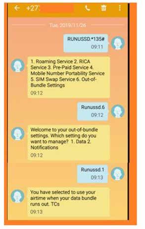
Contents
1.       INTRODUCTION                                              PAGE 9

1.1.     System Network Basics                                      Page 9
1.1.1.   G-Network of Devices                                       Page 10
         1.1.1.1 Scenario 1                                         Page 10
         1.1.1.2 Scenario 2                                         Page 10
         1.1.1.3 Scenario 3                                         Page 10

2.       G-ULTRA UNIT                                             PAGE 12

2.1.     Opening the Box                                          Page 12

2.2.     Unit Description                                         Page 12
2.2.1.   Technical Specifications                                   Page 12
2.2.2.   Terminal Block                                             Page 13
         2.2.2.1 Power Supply                                       Page 13
         2.2.2.2 Battery Backup                                     Page 14
		               2.2.2.2.1. Which Battery to Choose                 Page 14
		               2.2.2.2.2. Wiring Up the Battery                   Page 14
2.2.3.   Inputs / Outputs                                           Page 15
         2.2.3.1 Working With IO                                    Page 15
		               2.2.3.1.1. Steps to Configure                      Page 15
		               2.2.3.1.2. Rise and Fall Edges                     Page 15
         2.2.3.2. Working with Relays                               Page 16
		               2.2.3.2.1. Latching VS Pulsed                      Page 16

2.3.     Network Connectivity                                     Page 16
2.3.1.   Network Access from the Mobile Apps                        Page 16
2.3.2.   SIM Card                                                   Page 17
         2.3.2.1. Replacing the SIM Card                            Page 17
2.3.3.   Alternative Network SIMs                                   Page 17
2.3.4.   Checking or Replacing the SIM Card                         Page 17
         2.3.4.1. SIM Card Maintenance                              Page 18
         2.3.4.2. How to Remove the SIM Card                        Page 18
         2.3.4.3. How to Insert the SIM Card                        Page 18

2.4.     Installing the G-ULTRA                                   Page 19
2.4.1.   Unit Disassembly                                           Page 19
2.4.2.   Mounting the Unit                                          Page 20

2.5.     Powering Up the G-ULTRA                                  Page 20

2.6.     Configuring Features                                     Page 21

3.       LCD INTERFACE                                            PAGE 22

3.1.     Home Screen                                              Page 22

                                                    page 3   www.centsys.com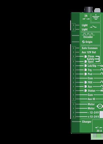
CONTENTS

3.2.     IO Status Screen                                                    PAGE 23

3.3.     Output Status Screen                                                Page 23

3.4.     Voltage / Firmware / Date & Time Screen                             Page 24

3.5.     Phone Number Screen                                                 Page 24

3.6.     Airtime Balance Screen                                              Page 25

3.7.     GSM Antenna Selected Screen                                         Page 25

3.8.     Gate Status Screen                                                  PAGE 26

3.9.     SIM Screen                                                          Page 26

3.10. IMEI Screen                                                            Page 26

4.       WIRING DIAGRAMS                                                     PAGE 27

4.1.     Gate Status Monitoring                                              Page 27

4.2.     Gate Trigger Pulse                                                  Page 28

4.3.     Wiring the G-ULTRA into a D-Series Controller                       Page 29

4.4.     Wiring the G-ULTRA into an Electric Fence                           Page 30

4.5.     Wiring a G-ULTRA into an Alarm System                               Page 31

4.6.     Wiring a G-ULTRA into a D-Series Controller via a Wizo              Page 32

4.7.     Wiring a G-ULTRA into an Electric Fence Controller via WiZo-Links   Page 33

4.8.     Wiring a G-ULTRA into an Alarm System via WiZo-Links                Page 34

5.       G-WEB                                                               PAGE 35

5.1.     Introduction to G-WEB                                               Page 35

5.2.     G-WEB Online                                                        Page 35
5.2.1.   Login / Create an Account                                             Page 35
5.2.2.   G-WEB Dashboard                                                       Page 36
         5.2.2.1.		 Wallet                                                     Page 36
         5.2.2.2.		 My Devices                                                 Page 36
			 5.2.2.2.1.                   Navigating the Device Listing                 Page 37

  5.2.2.2.2.                     Add Funds                                     Page 38
			 5.2.2.2.3.                   Add New Device                                Page 38
			 5.2.2.2.4.                   Synchronise / Synchronise Selected            Page 39
			 5.2.2.2.5.                   Delete Selected Devices                       Page 39
			 5.2.2.2.6.                   Clone Selected Device                         Page 39

  5.2.2.2.7.                     My Recharges                                  Page 40
			 5.2.2.2.8.                   Device Token Top-up                           Page 40

                                                    page 4             www.centsys.com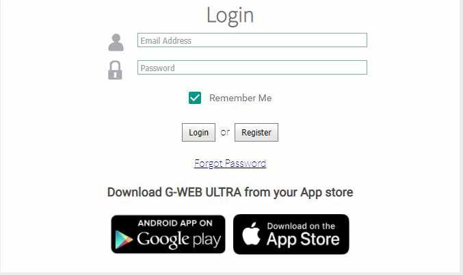
5.2.2.3. My Profile                                                          Page 40

  5.2.2.3.1.                   Personal Details			                                    Page 40

  5.2.2.3.2.                   Change Password                                        Page 41

  5.2.2.3.3.                   Security Settings		                                    Page 41
			 5.2.2.3.4.                 Notification Settings                                  Page 42
				                           View Wallet Statement                                  Page 42
				                           Company Details                                        Page 43
				                           Time Zone                                              Page 43
         5.2.2.4.		 My Contacts                                                       Page 44
			 5.2.2.4.1.                 Add Contact                                            Page 44
			 5.2.2.4.2.                 Delete Selected                                        Page 44
			 5.2.2.4.3.                 Edit Custom Fields                                     Page 45
			 5.2.2.4.4.                 Managing the Contact List                              Page 45
				                           Edit an Existing Number                                Page 45
				                           Delete a Single Number                                 Page 45
			 5.2.2.4.5.                 Export Contacts                                        Page 46
			 5.2.2.4.6.                 Import Contacts                                        Page 46
         5.2.2.5.		 Support                                                           Page 46
         5.2.2.6.		 Logout                                                            Page 47
5.2.3.   Managing and Configuring Individual Devices                                  Page 47
         5.2.3.1.		 Status                                                            Page 47
			 5.2.3.1.1.                 Device Status                                          Page 47
				                           Connection Information                                 Page 47
				                           Sync Details                                           Page 48
				                           General Information                                    Page 48
				                           Device Token Remaining                                 Page 49

  5.2.3.1.2.                   Logs                                                   Page 49
				                           Export Log Data                                        Page 50
				                           Sync Logs, Refresh                                     Page 50
				                           Delete, Delete All                                     Page 51
         5.2.3.2. Access Configuration                                                Page 51

  5.2.3.2.1.                   Access Numbers                                         Page 51
				                           Import Numbers                                         Page 51
				                           Updating the Access Numbers with the Template          Page 52
				                           Export Numbers                                         Page 52
				                           Add Access Number                                      Page 53
				                           Add Access Number From Contact List                    Page 53
				                           Delete Selected Numbers                                Page 54
				                           Edit Selected Numbers                                  Page 54
				                           Device Welcome Message                                 Page 55
				                              Edit the Welcome Message                            Page 55
			 5.2.3.2.2.                 Access Profile                                         Page 55
			 5.2.3.2.3.                 How to Add a Profile                                   Page 56
			 5.2.3.2.4.                 How to Edit a Profile                                  Page 56

  5.2.3.2.5                    Activations                                            Page 56

                                                    page 5                     www.centsys.com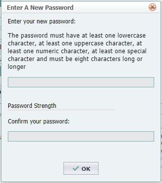
G-REMOTE                                              Page 57
				                           Configure Visible IO                                  Page 57
				                           Calls (DTMF / Missed Call)                            Page 58
			 5.2.3.2.6                  Notifications		                                       Page 59
			 5.2.3.2.7                  Notification Settings                                 Page 59
				                           Global Device Outgoing Notification Messages          Page 59
				                           Input Trigger Outgoing Notification                   Page 59
				                           Output Trigger Outgoing Notification                  Page 60
				                           Device Offline Notifications                          Page 60
				                           System Outgoing Notifications                         Page 61
			 5.2.3.2.8                  Enable / Disable Access Profiles                      Page 61
			 5.2.3.2.9                  Delete Access Profile                                 Page 61
			 5.2.3.2.10. Profile Activity Notifications (Recurring)                           Page 61
				                           Add Notification                                      Page 62
			 5.2.3.2.11. Profile Activity Notifications (Once Off)                            Page 63
				                           Messages                                              Page 63
         5.2.3.3.		 Settings                                                         Page 64
			 5.2.3.3.1.                 IO Settings                                           Page 64
				                           Configure an IO                                       Page 65
				                           Enable Gate Status Monitoring                         Page 65
				                           Configure an IO (relay)                               Page 65
			 5.2.3.3.2.                 Advanced IO Settings                                  Page 66
				                           Falling and Rising Edge Settings                      Page 66
				                           How to Set Falling Edge / Rising Edge                 Page 67
				                                      Configuring Output Channels                Page 67

  5.2.3.3.3.                   Time Window                                           Page 68
				                           Add a Time Window                                     Page 68
				                           Edit A Time Window                                    Page 69
				                           Enable / Disable A Time Window                        Page 69
				                           Delete A Time Window                                  Page 69
			 5.2.3.3.4.                 IO Mappings                                           Page 69
				                           Add an IO Mapping                                     Page 69
				                           Edit an IO Mapping                                    Page 70
				                           Delete an IO Mapping                                  Page 71
			 5.2.3.3.5.                 Output Activation Schedule                            Page 71
						Add Output Schedule                                                            Page 72
			 5.2.3.3.6.                 Exclusion Dates                                       Page 73
			 5.2.3.3.7.                 Advanced Power Settings                               Page 74

5.3.     G-WEB App                                                                 Page 74
5.3.1.   Installation                                                                Page 74
5.3.2.   Adding a Device                                                             Page 74
5.3.3.   Device Options                                                              Page 75
         5.3.3.1. Configure Device                                                   Page 75

  5.3.3.1.1                    Back                                                  Page 75

                                                    page 6                    www.centsys.com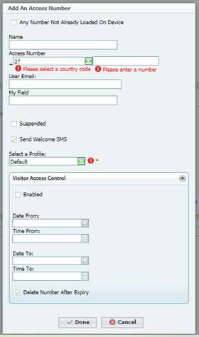
5.3.3.1.2                Info                                          Page 75
				                         Device Details                                Page 75
				                         Connectivity Details                          Page 76
				                         Device Tokens Remaining                       Page 76
     				                    Firmware Details			                           Page 76
			 5.3.3.1.3.               Access Numbers                                Page 77
			 5.3.3.1.4.               Access Profiles                               Page 77
				                         Adding a New Profile                          Page 77
				                         Editing the Profile                           Page 77
				                         Disable / Enable                              Page 78
				                         Delete a Profile                              Page 78

  5.3.3.1.5.                 Sync                                          Page 78

  5.3.3.1.6.                 Logs                                          Page 78

  5.3.3.1.7.                 Settings                                      Page 78
				                         IOs                                           Page 78
				                                Configure IO                           Page 79
				                                Configure a relay output               Page 79
				                                Configure A Button                     Page 80
				                                Disable / Enable                       Page 80
				                         IO Mapping                                    Page 80
				                                Editing / Deleting IO Mapping          Page 81
				                         Power Saving                                  Page 81
			 5.3.3.1.8.               Scheduled Activations                         Page 81
			 5.3.3.1.9.               Exclusion Dates                               Page 82
			 5.3.3.1.10. SMS Commands                                               Page 82
				                         How to Send Commands                          Page 82
			 5.3.3.1.11. Time Periods History                                       Page 83
				                         How to Add a Time Period                      Page 83
			 5.3.3.1.12. History Logs                                               Page 83

  5.3.3.1.13. Support                                                      Page 83
       5.3.3.2.		 Wizard                                                   Page 83
			 5.3.3.2.1                Device Application Wizard                     Page 84
       5.3.3.3.		 Clone Device                                             Page 85
       5.3.3.4.		 Transfer Device                                          Page 85
       5.3.3.5.		 Add Secondary User                                       Page 85
       5.3.3.6.		 Delete Device                                            Page 86

6.     G-REMOTE                                                          Page 86

6.1.   Introduction                                                      Page 86
6.2    Installing the App                                                Page 86
6.3    Using G-REMOTE                                                    Page 86
       6.3.1.		 G-REMOTE Landing Page / Favourites List                    Page 86

  6.1.3.1.1                  G-ULTRA Device Landing Page                   Page 87
       6.3.2.		 Using and Customising Buttons                              Page 87
			 6.3.2.1.                 Activating the Button                         Page 87

                                                   page 7           www.centsys.com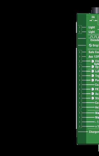
6.3.2.2.                 Deactivate the Button                                  Page 87
			 6.3.2.3.                 Add to Favourites                                      Page 87
			 6.3.2.4.                 Enter a Name for the Button                            Page 88
			 6.3.2.5.                 Change the Button Colour                               Page 88

  6.3.2.6.                   Change Icon			                                         Page 88
       6.3.3.		 Input Actions                                                       Page 89
       6.3.4.		 Device Notifications                                                Page 89
       6.3.5.		Information                                                          Page 89

  6.3.5.1.                   Device Info		                                          Page 89
       6.3.6.		 Send Commands                                                       Page 90
			 6.3.6.1.                 How to Send Commands                                   Page 90
       6.3.7.		Settings                                                             Page 90
			 6.3.7.1.                 All Devices                                            Page 90
			 6.3.7.2.                 Selected Device                                        Page 91
				                         How to Change Notification Type                        Page 91
       6.3.8.		 Refresh Permissions                                                 Page 91
       6.3.9.		About                                                                Page 91

7.     TROUBLESHOOTING                                                           Page 92

7.1.   My Device is Not Connected to G-WEB                                          Page 92

         This icon indicates tips and other information that could be useful during the
         installation.

         This icon denotes variations and other aspects that should be considered during
         installation.

         This icon indicates warning, caution or attention! Please take special
         note of critical aspects that MUST be adhered to in order to prevent
         injury.

                                                 page 8                     www.centsys.com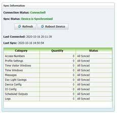
SECTION 1                                                                     INTRODUCTION

1. Introduction

The G-ULTRA is a remote monitoring and control system which is GSM-enabled.
Leveraging the power of GSM, the unit is capable of monitoring and / or controlling a
variety of systems and devices using a mobile device.
One or more G-ULTRA devices can be linked using G-WEB, Centurion Systems’s online
system that enables the user to group their G-ULTRAs, configure and manage them, and
purchase airtime.
GSM is an established and inexpensive technology, and the G-ULTRA leverages the
many benefits of its reliability to produce a flexible, mobile-based access control and
monitoring system.

1.1. System Network Basics
As shown in the image below, the G-ULTRAs require cellular network access. G-ULTRAs
can be set up at the same location, e.g. a home or business, or at different locations and
yet still be controlled, and monitored via the same mobile device in tandem with G-WEB.

         It is essential to perform a network coverage check at the installation location
         to ensure that network coverage is available and that if the G-ULTRA requires
         an antenna it is installed. Since many factors impact network coverage, this is a
         best-effort approach to connectivity and poor or intermittent network coverage
         may impact system operation.

Since the G-ULTRA is GSM-enabled, i.e. includes a built-in GSM modem, the unit
requires a SIM card. The network provider for the G-ULTRA unit is MTN (South Africa
only). Using MTN’s extensive network, the G-ULTRAs can be configured, monitored,
managed and airtime purchased for their operation. “Airtime “, referred to as tokens,
are required to ensure that the G-ULTRA stays connected to the network. These are
available via G-WEB.

                                                                                FIGURE 1.

                                           page 9                            www.centsys.com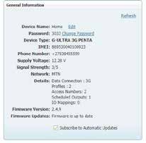
SECTION 1                                                                    INTRODUCTION

        Between the mobile device controlling the G-ULTRAs and the cellular network,
        this path is network agnostic; it does not matter which network is used.
        However, between the G-ULTRA and the cellular network, this is MTN network
        centric.

1.1.1. G-Network of Devices

        The following information is conceptual and will define and describe some
        options users have to create G-Networks.

In the scenarios described below, two applications are used to operate and configure
a G-Network: these are G-WEB, for configuration and G-REMOTE for operating and
interacting with the G-ULTRA. Only one instance of G-WEB would be needed or required
to create a network of devices, and multiple users would be able to control or interact
with the network.
Depending on the user, they can also have access to multiple networks of devices.
Devices do not necessarily need to be located at the same premises and therefore can
be anywhere within South Africa. The two scenarios are for illustrative purposes and do
not limit the product in any way; they are intended to assist in conceptualising the usage
potential.

1.1.1.1. Scenario 1

Frank is on the board of trustees, and he is the complex maintenance coordinator.
They recently installed a CENTURION D-Series Gate Operator, the G-ULTRA, and other
CENTURION products. He installed the G-WEB app on his phone and used G-WEB
to configure the complex security gate to allow the opening and closing of the gate
remotely. He then installed the G-REMOTE app on his phone, and he tested the operation
using G-REMOTE. Since he was happy with the operation, he instructed the residents
to install G-REMOTE. He already had their numbers, so he added them as Users and
enabled them to activate the gate.
The complex residents then installed G-REMOTE and were able to immediately open and
close the gate using their phone.

                           Network of devices             Admin
                                                                              Lerato

     Complex                                                Scott              Candice
                                                                              FIGURE 2.

                                          page 10                          www.centsys.com
SECTION 2 NETWORK REDUNDANCY
1.1.1.2. Scenario 2
Candice lives in the same complex as Lerato. Recently, there had been security issues
with the old system, and she was happy to hear that a new system was being installed.
She received a link on WhatsApp directing her to install an app galled G-REMOTE. She
tapped on the link, found herself in the AppStore, and then clicked install. Once the
G-REMOTE app was installed, she opened it, clicked on the name of her complex on the
main screen, and saw a collection of large, easy to read colour-coded buttons. Just then,
her mom messaged her from the gate, and she tapped the easy to see Open Gate button
and could see from her lounge window, the gate opening.
1.1.1.3. Scenario 3
Lerato and Candice were impressed with the way that the new CENTURION products had
improved security at their complex. They decided to install a similar setup at their small
business premises. Thinking it would be difficult, they approached Frank and asked for
help. He said there was no need, as all they needed to do was to install the G-WEB app
on their phone, follow the easy instructions to link the new device, and then to also link
their phone to their G-WEB profile. He then showed them how to link the new, separate
G-ULTRA device so that it displayed in G-REMOTE.
Dumisani spends more time out of the office, and now Candice can open and close the
gate from her phone. During the day, it has been very convenient to let clients and
suppliers in and out of the premises as the old wired system kept breaking especially
after a lightning storm. Now, the quick response of the remote system has made it easy
and she can open it from wherever she is, as she does not need to go to the front of the
office to press a button.
It also proved very useful over the weekend when the armed response security needed
to gain entry to the premises, and they were able to 1) open the gate 2) wait on the
response that the alarm had been reset 3) were able to monitor the gate closure
remotely until closed.
Complex
Admin
Lerato
Network of devices
Users
Small business Candice
FIGURE 3.
page 11 www.centsys.comSECTION 2 G-ULTRA UNIT
2. G-ULTRA UNIT
2.1. Opening the Box
The following details pertain to the G-ULTRA; ensure to make note of the items
mentioned.
Before opening the box, you will notice on the side of the box key information you will
require later. They are the following items:
• IMEI Number; this uniquely identifies the GSM unit
• Password: this is a 4-digit number that is already configured for the device
Ensure that the flap of the box is retained or that you record the information using your
phone by taking a picture or by recording the information by other means.
2.2. Unit Description
The unit is compact but releases easily from the box once you carefully cut through the
tamper-proof seal that protects both sides of the box. If this seal is compromised, return
your purchase.
2.2.1. Technical Specifications
The following specifications describe the Key Features and operating Requirements for
the G-ULTRA.
Item Description
Supply Voltage Range 11-24V DC
Maximum Current Draw 300mA @ 12V DC
Input/output Current Rating 50mA (Open Collector)
Relay Contact Current Rating 1A, 30V AC/DC (Resistive)
0-24V DC (0-1.6V Low-input State, 5V-24V
Input Sense Voltage Range
High-input State)
Network Provider MTN (South Africa only)
Number
2.4.1. of Configurable
Establishing IO Channels
the Network 4
Number of Relays 21
TABLE 1.
1. A relay will allow for a higher current load to be switched on using the G-ULTRA
page 12 www.centsys.comSECTION 2 G-ULTRA UNIT
2.2.2. Terminal Block
Shown here are the Terminal Block
connections for G-ULTRA. You gain
access to the terminal block by
G-ULTRA RELAY 1 RELAY 2
removing the cover, which lifts free GND IO1 IO2 IO3 IO4 NO COM NC NO COM NC + VDC -
from the unit’s base
FIGURE 4.
GND Ground
IO1 Input / Output 1 (Default: Output)
IO2 Input / Output 2 (Default: Output)
IO3 Input / Output 3 (Default: Output)
IO4 Input / Output 4 / Gate Status Input (Default: Output)
NO Relay 1 Normally-open
COM Relay 1 Common
NC Relay 1 Normally-closed
NO Relay 2 Normally-open
COM Relay 2 Common
NC Relay 2 Normally-closed
+ Positive of Power Supply 12-24VDC
- Negative of Power Supply
TABLE 2.
2.2.2.1. Power Supply
The G-ULTRA utilises a DC (Direct Current) power supply, with an acceptable input range
from 11 Volts DC to 24 Volts DC. The G-ULTRA can therefore be powered by a battery of
suitable output, or suitable DC Power supply.
• Ensure sufficient input voltage is supplied so that the G-ULTRA powers up
correctly
• Do not oversupply the G-ULTRA as this WILL damage the unit
• DO NOT power the unit directly from an Alternating Current (AC), Mains, or
normal household socket supply as this WILL destroy the G-ULTRA
The common standard for wire G-ULTRA RELAY 1 RELAY 2
colours for a DC connection is red GND IO1 IO2 IO3 IO4 NO COM NC NO COM NC + VDC -
and black: red positive and black
negative. Following this wiring
convention will make the connections
simpler, and 2-core cabling is readily
available using this scheme.
+Ve -Ve
Shown left is the power connections
which need to be active to be able to
FIGURE 5.
sync the G-ULTRA device.
page 13 www.centsys.comSECTION 2 G-ULTRA UNIT
2.2.2.2. Battery Backup
The G-ULTRA can be powered from a battery backup system in the event of a power
failure, and this can be tied into the Advanced Power features. You have the choice of
two options to power either from a 12V or a 24V battery, and this is within the DC power
supply range of the device.
2.2.2.2.1. Battery Backup
The battery often used for a
G-ULTRA is a standard 12V 7 Ah,
sealed lead-acid battery. These are
often used in UPS (Uninterruptable
Power Supply) and are inexpensive
and readily available.
With the range of batteries, the
Ampere Hour or Ah rating does
correlate to the physical size of
the battery and for how long the
G-ULTRA could be powered.
The G-ULTRA draws 300 mA at
12V, so 7 Ah / 300mA = 23.3 hours.
Your G-ULTRA in theory would
then have close to 24 hours running
time during load shedding, for
example. This time is theoretical,
as the condition of the battery and
other factors can impact on the
battery, reducing the time it can be
FIGURE 6.
a backup.
2.2.2.2.2. Wiring Up the Battery
As shown in the image below, the
battery is connected in line with the
G-ULTRA and therefore it charges
and is part of the power circuit at
the same time. Good practice would
G-ULTRA RELAY 1 RELAY 2
be to include a diode in-line with the GND IO1 IO2 IO3 IO4 NO COM NC NO COM NC + VDC -
positive wiring before the battery
and after the power supply. Charge
voltage for a SLA is 13.7V, so to
compensate for the diode which
needs 0.6V to work, your total input
voltage would be 14.3V. The reason +Ve -Ve
for the diode is that, while the power
supply is active, it is providing power
but when there is a power failure,
the power supply can effectively
become a load and help drain the
battery. The diode protects the
battery and ensures that only the FIGURE 7.
G-ULTRA is using it.
When the battery is included, strict adherence to the maximum input voltage
must be applied to avoid overcharging the battery. If overcharged, this can
lead to excessive heat and a potential fire hazard.
page 14 www.centsys.comSECTION 2 G-ULTRA UNIT
2.2.3. Inputs / Outputs
The G-ULTRA offers four individually-configurable channels (IO) and two Relay Outputs
can be mapped to either trigger a notification or activate an output. These are configured
using the G-WEB application or website.
Input 4, is a dual-purpose input that can be assigned to monitor the condition or
state of a gate operator of a gate closing. Only Input 4 can be assigned to this
role, and a D-Series Motor controller is used to provide the input data. Input 4 is
configured using the G-WEB application or website. If more than one gate needs
to be monitored, then two G-ULTRAs would be required
2.2.3.1. Working With IO
The G-ULTRA’s IO are highly configurable and enable the user to map them internally
to either the IO’s located at positions 1-4 or the mechanical relays at relay output 5 and
6. An input can be configured as a trigger to an output. This can be as simple as a push
button interaction, for example, a security office pushing a button in an office to open a
gate or to buzz a door open.
2.2.3.1.1. Steps to Configure
Configuring an input has two main steps; the first is to configure an IO as an input, which
is done on the IO settings page. The second step, once the IO has its designation, is to
configure the advanced features of the IO on the Advanced IO settings page.
2.2.3.1.2. Rise and Fall Edges
Rise Edge refers to the time it takes for the leading edge of a pulse (voltage or current)
to rise from its minimum to its maximum value. Rise Edge is typically measured from
10% to 90% of the value. Conversely, Fall Edge is the measurement of the time it takes
for the pulse to move from the highest value to the lowest value. In a resistive circuit,
Rise Time values are primarily due to stray capacitance and inductance, which cause a
delay in voltage and/or current until the steady state is reached. In terms of application,
when measuring a waveform on an oscilloscope, the faster the Rise Edge, the more
accurate the measurement.
When using the Rise and Fall elements of an input pulse, it is important to consider how
this may affect the day-to-day operation of the system, and how you wire the push
button in, for example. The two ways would be to:
1. Wire a push button so that it’s normally-closed i.e. there is always power active
on the input until the push button is pressed. The power then goes from high to
low or has a falling edge, i.e. on to off
2. Alternatively, the push button is wired so that the power is only present on the
input when the push button is pushed, and so has a rising edge i.e. off to on
page 15 www.centsys.comSECTION 2 G-ULTRA UNIT
In an ideal world, we would have
clean signals moving between
the switch and the input, but in
IDEAL
the real world owing to electrical
characteristics of materials, transient
power surges and interference, any Rising Falling
number of events can appear like a edge edge
valid input signal, but it is not. As
shown in the image below, what is REAL
anticipated by us in the ideal world
is offset by what may happen and a
poorly formed input signal may be Time TABLE 2
valid or just interference.
FIGURE 8.
2.2.3.2. Working with Relays
A relay is a mechanical component that can be triggered to switch a device on or off
depending on how it is set up and wired.
2.2.3.2.1. Latching VS Pulsed
A relay is a mechanical component that can be triggered to switch a device on or off
depending on how it is set up and wired.
An example is where the G-ULTRA is used to switch a pump on, and it stays on until the
float mechanism triggers the G-ULTRA to switch the relay off.
Pulsed, is the change from the current state to a new state momentarily or for a short
time and then automatically switches back to the original state.
An example would be a day-night switch, where the motion sensor triggers the relay, but
it only stays on for a few seconds or minutes before switching off regardless of whether
the action which caused the trigger is still active.
2.3. Network Connectivity
2.3.1. Network Access from the Mobile Apps
Mobile apps have been provided without cost, and these apps enable you to configure
and use a configured device. When you use the mobile apps for monitoring and
configuring the device, no costs to you are incurred for the life of the product, provided
that a CENTURION MTN SIM is used
CENTURION MTN SIM cards can only be recharged using the G-WEB online
platform or G-WEB mobile app.
For costs incurred when making use of SMS notifications you will need to purchase
CENTURION tokens via G-WEB
page 16 www.centsys.comSECTION 2 G-ULTRA UNIT
2.3.2. SIM Card
The unit is supplied with a NANO
SIM card. The SIM card is visible G-ULTRA Fascia
when the top cover plate is removed,
and the unit tipped to the side. The
SIM card is held in place by a push
to release the SIM cardholder.
The SIM card supplied is an MTN
SIM card, which is contracted via
CENTURION to MTN. The supplied
SIM card is not standard and can
only be used in the G-ULTRA, and Main G-ULTRA
other CENTURION products where Unit
applicable. It cannot be used in
mobile phones or any other standard
mobile device for communication
FIGURE 10.
purposes.
2.3.2.1. Replacing the SIM Card
When replacing the SIM card, ensure
Standard
to detach the NANO SIM, which is
the innermost detachable section as Micro
shown in the image. Nano
Follow the instructions below to
insert the SIM card.
FIGURE 11.
2.3.3. Alternative Network SIMs
The G-ULTRA has been supplied with a SIM which has been configured to work
exclusively with the MTN network, and this offers many convenient features when
recharging the SIM with tokens. The G-ULTRA is not a networked locked device, and you
can remove the supplied SIM and use a SIM supplied by any of the local South African
networks. If an alternative SIM is used, you will still be able to configure the unit using
G-WEB; however, managing the device’s airtime and network access won’t be available
and will have to be managed externally.
page 17 www.centsys.comSECTION 2 G-ULTRA UNIT
2.3.4. Checking or Replacing the SIM Card
2.3.4.1. SIM Card Maintenance
Under normal circumstances, the SIM card should function indefinitely provided the
G-ULTRA is not subjected to a harsh environment. Harsh environments are ones where
the G-ULTRA is exposed to dust, corrosive chemicals either directly or indirectly through
atmospheric exposure or environments where there is a high degree of static and/or
electrical interference.
However, in the event that the G-ULTRA loses connectivity, and the SIM card is
suspected, the SIM card can be removed and cleaned or replaced. Cleaning would involve
using a normal eraser to remove any carbon or particle build-up. If this does not solve
the connectivity issue, the SIM card may need to be replaced.
Please follow the instructions in the next section on removing and replacing the SIM card.
2.3.4.2. How to Remove the SIM Card
Removing the SIM card, when required, is performed by doing the following:
1. Power down the G-ULTRA, then attempt the SIM removal
2. Using the closed edge of a tweezer, press against the flat edge of the SIM card. Apply
firm, even pressure
3. A very slight click will be heard and then the SIM card will release
4. Once ejected, use a pair a tweezers to remove from the slot
2.3.4.3. How to Insert the SIM Card
Inserting the SIM card, when required, is performed by doing the following:
1. Ensure that the SIM card is orientated correctly. Use the monogrammed image on the
chassis
2. Using a pair of tweezers, insert the SIM card into the slot
3. Using the closed edge of the tweezers along the flat edge of the SIM card, push the
SIM card down using firm, even pressure until you feel resistance. If a slight click is
felt and/or heard, then the SIM card is secure
4. Release the pressure from the SIM card and it should now remain in the slot
5. Visually inspect the inserted SIM card and ensure that it has been securely inserted
6. Power up the G-ULTRA
page 18 www.centsys.comSECTION 2 G-ULTRA UNIT
2.4. Installing the G-ULTRA
Installing the G-ULTRA requires some degree of technical skill working with tools
to mount the unit onto a solid surface of differing materials. It is advisable to defer
mounting the unit to either trained or experienced personnel if you do not possess the
appropriate know-how.
2.4.1. Unit Disassembly
The G-ULTRA has been designed with quick disassembly and installation in mind. As can
be seen, the G-ULTRA unclips into three separate pieces.
1
7
6
2
3
5
4
FIGURE 12. PRODUCT IDENTIFICATION
1. Fascia
2. External Antenna Cover
3. Main G-ULTRA Unit
4. Mounting Plate
5. Terminal Blocks
6. Navigation panel
7. LCD Screen
While the G-ULTRA is constructed from quality and durable materials, the unit
or its components should not be subjected to an environment of temperature
extremes, highly corrosive chemicals, or noxious environments.
page 19 www.centsys.comSECTION 2 G-ULTRA UNIT
2.4.2. Mounting the Unit
With the mounting plate removed, you will notice many mounting positions molded into
the plate.
For ease of installation, we recommend that you use the mounting plate as a template to
mark off the mounting positions.
1. Identify a suitable location for
the G-ULTRA, and ensure that
the unit will not be mounted in Mounting
screws
the path of any sources of water, (Not Supplied)
condensation, or mold.
2. Using the mounting plate as a
template, mark off the holes
using a pencil or a sharp object
which will leave a visible mark on
the wall or the surface where the Wall
anchors
unit will be mounted. Ensure that
the plate is facing the correct Mounting
way i.e. square slot down, as Plate
shown in the image below.
3. Remove the mounting plate FIGURE 13.
from the surface and use the
appropriate size drill to create
the mounting holes.
4. Once the holes have been drilled,
secure the mounting plate to the
surface and ensure the mounting
plate is sitting flush against the
wall.
5. The main G-ULTRA unit can
now be clipped back into the G-ULTRA Mounting
mounting plate. Main Unit Plate
FIGURE 14.
It is not advised that you drill directly through the mounting plate as this may
damage the plate, especially if a mortise drill bit is used.
With the unit now securely mounted, you can proceed with wiring up the unit.
2.5. Powering Up the G-ULTRA
Please see the following section: Power Supply, for details on the power connections.
To power up the unit, supply the required minimum power to the G-ULTRA and the LCD
screen will switch on displaying the words “G-ULTRA” and the CENTURION logo. This is
the startup screen, and this will be displayed for roughly 10 seconds, and then the Home
Screen will display.
The Home Screen will light up using the LCD backlight and after a short while the
backlight will switch off. The LCD Interface enables you to view the current status of the
G-ULTRA; however, it does not allow you to configure any features from the G-ULTRA
itself.
page 20 www.centsys.comSECTION 2 G-ULTRA UNIT
To configure the G-ULTRA, you require one of the following:
1. A PC or Laptop with a stable Internet connection
2. A Mobile phone running either Android (Non-brand specific or IOS (iPhone)
3. An Android device or an IOS device
Old style mobile devices which are not smartphones will not support the mobile
app.
2.5. Configuring Features
Apps work together to enable the
G-ULTRA to be configured and
controlled. G-WEB which is available
as a website and also as an app
for your mobile device, G-REMOTE,
which enables authorised users to
activate and monitor one or more
G-ULTRAs.
G-WEB is therefore the
administrative application, and
G-REMOTE would normally be used
by an end-user. For example, in a
Residential Complex, G-WEB would
be used to configure the gate access
control and then G-REMOTE would
be used by the residents to open the
gate to gain entry. FIGURE 15.
page 21 www.centsys.comSECTION 3 LCD INTERFACE
3. LCD INTERFACE
The G-ULTRA employs a user-friendly and concise menu system which is operated from
the unit’s keypad. The LCD (Liquid Crystal Display) enables the user to navigate through
many different screens that will display the system’s status and system settings.
G-ULTRA system settings and configuration are done using G-WEB, and to
activate or use these features G-REMOTE is used.
3.1. Home Screen
The Home Screen is the default screen and is displayed once the device has powered up.
HOME SCREEN
Indicates network signal strength. Depending on
network access, either a 2G or 3G indicator will
appear
Indicates connection to the internet; however,
does not indicate a connection to G-WEB
Indicates when a connection to G-WEB is active
The device has an error
Incoming or inbound message
Outgoing or outbound message. This action
consumes a token per event
Incoming call events
Outgoing Phone call events. This action consumes
a token per event
TABLE 3.
page 22 www.centsys.comSECTION 3 LCD INTERFACE
3.2. Home Screen
The IO (Input / Output) are four user-configurable, bi-directional IO. This flexibility
enables the user to determine how each of the four are used and to configure
accordingly. Each IO can be either an input or an output. IO 4 has a special feature and
has a third function as the input for the Gate Status monitoring.
IO STATUS SCREEN
When the circle is light, this indicates that the
input is deactivated. The small “E” indicates that
an input event has occurred, and no action takes
place since the input is not active
When the circle is dark, this indicates that the
input is activated.
The output is off.
The output is on*.
TABLE 4.
For the IO, which excludes the available two mechanical relays, an input or
output is considered active “on”, high when pulled low.
3.3. Output Status Screen
The output status screen displays the status of the two mechanical relay outputs.
Mechanical relays are usually used to switch a high-current/voltage load and should be
used for this purpose.
OUTPUT STATUS SCREEN
For example, illustrates that the relay is in the
Normally-Open position.
NC2
COM1 COM2
NO1
For example, illustrates that the relay is in the
Normally-Closed position.
TABLE 5.
page 23 www.centsys.comSECTION 3 LCD INTERFACE
3.4. Voltage / Firmware/ Date And Time
This menu indicates key operating conditions for the device
VOLTAGE / FIRMWARE/ DATE AND TIME
The Supply Voltage indicator is used to indicate
the measured input Supply voltage. The value
Supply displayed will update at system power-up
Voltage and update periodically but does not update
dynamically if the input voltage changes suddenly
or changes from one value to another
The Firmware version number indicates the
current revision of firmware installed on the
G-ULTRA. This may differ from the version of
firmware that is available. If the version is older
Firmware i.e. version 2.4.9 is installed but 2.5.0 is available,
this may indicate that 1) the device is performing
a self-update 2) the Automatic Updates setting has
been disabled 3) there may be insufficient credits
in your account
The time as provided by the cellular network.
Time If daylight saving has been enabled, the time will
display accordingly
The Date and Time displayed is provided by the
internal Real Time Clock. The regional setting
Date for the time can be selected using G-WEB under
Settings > Clock Settings, configuring the regional
setting and then syncing this to the G-ULTRA
This should not be viewed as a voltmeter as this is not its
purpose. For this reason, a fixed voltage supply should be used
and not a variable output supply to avoid either over- or under-
supplying the G-ULTRA
Firmware updates are without charge; however, network access
costs may apply.
Day Light Saving as a feature is available and is configured in
G-WEB under Settings > Clock Settings and then syncing this to
the G-ULTRA.
3.5. Phone Number Screen
PHONE NUMBER SCREEN
The phone number listed on the screen is the number assigned
to the SIM card loaded on the G-ULTRA. This would be
an MTN cell number, in international format; for example:
+27XXXXXXXXXX. If the SIM card is changed, then the number
will change automatically as well, and the new number will be
displayed on the screen.
TABLE 7.
page 24 www.centsys.comSECTION 3 LCD INTERFACE
3.6. Airtime Balance Screen
The airtime balance reports on the remaining balance airtime credits, credited to the
G-ULTRA on the current SIM card.
AIRTIME BALANCE SCREEN
The SIM card requires outgoing call credits or
tokens. The balance is displayed here.
The SIM card requires outgoing SMS credits or
tokens. The balance is displayed here.
TABLE 8.
3.6. GSM Antenna Selected Screen
The default setting is to use the internal antenna, and this should be adequate for
most applications where the G-ULTRA is located in an area which has average to good
network coverage. If the G-ULTRA does not receive commands or takes a long time to
send notifications, this may indicate that the network coverage is intermittent or poor
and an antenna can be attached to compensate for this and assist in improving the
reception.
GSM ANTENNA
Internal GSM antenna is selected (Default).
External GSM Antenna is selected.
Press enter to toggle between the internal /
external antenna.
If you change the Antenna selection on the G-ULTRA, ensure that when
the external antenna is selected, one is attached. If one is not attached, you
may experience network connectivity issues. This can only be changed at the
G-ULTRA itself.
TABLE 9.
3.6.1. Change Antenna Settings
To change the antenna setting, do the following:
1. Using the scroll buttons, scroll to the Antenna menu, and press enter
2. Press the arrow keys to change and toggle antenna selection
3. Press enter again to save the change
4. The unit will display a countdown from 5 to 0, and display an hourglass Icon to
indicate that the Antenna change is in progress
page 25 www.centsys.comSECTION 3 LCD INTERFACE
3.7. Gate Status Screen
The Gate Status screen displays the state of the gate assigned to IO4. This is configured
using the G-WEB application, and the IO is assigned as a gate monitoring input. This
configuration requires that a D-Series controller for example is in place, connected to the
G-ULTRA, and has been configured to monitor the gate status.
Please see the gate wiring diagrams section to view the implementation options and
information.
GATE STATUS SCREEN
Gate is closed.
Gate is in the process of opening or closing
Gate is open.
Gate Status warning.
IO 4 must be configured as the Gate Status input for this feature
to be available.
TABLE 10.
3.8. SIM Screen
SIM SCREEN
SIM PIN OK. This will display and then the screen
will no longer be available.
The SIM PIN was incorrect. The SIM will remain
SIM locked and the G-ULTRA device will not receive or
PIN: 1/0 send events.
The SIM has encountered an error. This may
require that the SIM be replaced or cleaned.
IO 4 must be configured as the Gate Status input for this feature
to be available.
TABLE 11.
3.9. IMEI Screen
As with all GSM devices, the IMEI number uniquely identifies the unit.
IMIE NUMBER
G-ULTRA This displays the device’s unit IMEI number. It will also display
12 34 5678 9012 345
the custom name assigned to the device above the IMEI number.
The name G-ULTRA, is editable using G-WEB.
TABLE 12.
page 26 www.centsys.comSECTION 4 WIRING DIAGRAMS
4. WIRING DIAGRAMS
In the wiring options below, configuring the operation is a two-part process.
1. G-WEB is used to enable / configure the feature
2. Physical and correct wiring must be completed so that the feature functions
as expected.
4.1. Gate Status Monitoring
These wiring instructions implement the physical requirements for the Gate Status
Monitoring feature, which is configured in G-WEB.
Pre-requisite check: For this feature to function, G-WEB must be configured to
enable gate status monitoring on IO4.
1. Before you begin, ensure that all devices have been powered down and the
power (AC Mains and battery backup) has been disconnected.
2. Ensure that any new wiring does not change or compromise existing
connections.
1. The IO connector strip is located under the main cover of the G-ULTRA. Carefully
remove the cover to expose them
2. Using a small flat screwdriver, release the screws but without removing them to allow
easy insertion for the wiring
3. Once you have prepared the ground wire:
a. On the G-ULTRA, common the GND and the VDC (minus) terminals
b. Now connect the G-ULTRA to the VDC(Minus) terminal to the COM of the
D-Series controller
4. Connect IO4 to the STATUS output on the D-Series controller, if not already connected
5. Connect the +VDC terminal of the G-ULTRA to the Aux 12v out of the D-Series
Controller
6. Once you have checked all connections, you may then power up the system
Gate Status Monitoring D-Series
Controller
Do not mount close to DOSS sensor or remote receiver.
G-ULTRA
GND IO1 IO2 IO3 IO4 NO COM NC NO COM NC + VDC -
FIGURE 17.
page 27 www.centsys.comSECTION 4 WIRING DIAGRAMS
4.2. Gate Trigger Pulse
These wiring instructions implement the physical requirements for the Trigger Pulse
feature, which activates the gate.
Prerequisite check: For this feature to function, Relay X must be configured to
close momentarily and then open, or pulse. Relay 1 or Relay 2 may be used;
the instructions below detail the use of Relay 1.
1. Before you begin, ensure that all devices have been powered down and the
power (AC Mains and battery backup) has been disconnected.
2. Ensure that any new wiring does not change or compromise existing
connections.
1. The IO connector strip is located under the main cover of the G-ULTRA. Carefully
remove the cover to expose them
2. Using a small flat screwdriver, release the screws but without removing them to allow
easy insertion for the wiring
3. Once you have prepared the ground wire:
a. On the G-ULTRA, common the GND and the VDC (minus) terminals
b. b.Now connect the G-ULTRA to the VDC(minus) terminal to the COM of the
D-Series controller
4. Connect IO4 to the STATUS output on the D-Series controller, if not already connected
5. Connect the +VDC terminal of the G-ULTRA to the Aux 12v out of the D-Series
Controller
6. Once you have checked all connections, you may then power up the system
Trigger (Pulse) D-Series
Controller
Do not mount close to DOSS sensor or remote receiver.
G-ULTRA
GND IO1 IO2 IO3 IO4 NO COM NC NO COM NC + VDC -
FIGURE 18.
page 28 www.centsys.comSECTION 4 WIRING DIAGRAMS
4.3. Wiring the G-ULTRA into a D-Series Controller
1. Before you begin, ensure that all devices have been powered down and the
power (AC Mains and battery backup) has been disconnected.
2. Ensure that any new wiring does not change or compromise existing
connections.
Possible Activations Possible Notifications
• Trigger Open • Gate Open / Closed
• Pedestrian Open • Gate Opening / Closing
• Free Exit / Keep Open • Gate Standing Open
• Holiday Lock • Mains Failure
• Battery Low
• Multiple Collisions
G-ULTRA RELAY 1 RELAY 2
GND IO1 IO2 IO3 IO4 NO COM NC NO COM NC VDC
TRG
PED
FRX
STATUS
LCK
+12V
COM
D-Series
Controller
FIGURE 19.
page 29 www.centsys.comSECTION 4 WIRING DIAGRAMS
4.4. Wiring the G-ULTRA into an Electric Fence
1. Before you begin, ensure that all devices have been powered down and the
power (AC Mains and battery backup) has been disconnected.
2. Ensure that any new wiring does not change or compromise existing
connections.
This wiring diagram can be used in conjunction with the G-WEB wizard
Possible Activations Possible Notifications
• Arm / Disarm • Arm Status
• Alarm Notifications
G-ULTRA RELAY 1 RELAY 2
GND IO1 IO2 IO3 IO4 NO COM NC NO COM NC VDC
GND
STATUS
ALARM
KEYSWITCH
KEYSWITCH
+12VDC
Strobe Siren
Relay Relay
NC NC
COM
NO NO
+ - + -
16VAC STROBE SIREN KEYPAD
+ - + -
+12 GND DAT GATE IN1
Electric Fence control board
FIGURE 20.
page 30 www.centsys.comSECTION 4 WIRING DIAGRAMS
4.5. Wiring a G-ULTRA into an Alarm System
1. Before you begin, ensure that all devices have been powered down and the
power (AC Mains and battery backup) has been disconnected.
2. Ensure that any new wiring does not change or compromise existing
connections.
This wiring diagram can be used in conjunction with the G-WEB wizard
Possible Activations Possible Notifications
• Arm / Disarm • Arm Status
• Intruder / Siren
G-ULTRA RELAY 1 RELAY 2
GND IO1 IO2 IO3 IO4 NO COM NC NO COM NC VDC
GND
STATUS
ALARM
GND
KEYSWITCH
KEYSWITCH
+12VDC
GND Z1 C
Alarm Panel
FIGURE 21.
page 31 www.centsys.comSECTION 4 WIRING DIAGRAMS
4.6. Wiring a G-ULTRA into A D-Series Controller via a WiZo-Link
1. Before you begin, ensure that all devices have been powered down and the
power (AC Mains and battery backup) has been disconnected.
2. Ensure that any new wiring does not change or compromise existing
connections.
This wiring diagram can be used in conjunction with the G-WEB wizard
Possible Activations Possible Notifications
• Trigger Open • Gate Open / Closed
• Gate Opening / Closing
• Gate Standing Open
• Mains Failure
• Battery Low
• Multiple Collisions
G-ULTRA RELAY 1 RELAY 2
GND IO1 IO2 IO3 IO4 NO COM NC NO COM NC VDC
TRG
STATUS
GATE
GND
WiZo
+12VDC
IN
NO
COM
NC
WiZo
IN
NO
STATUS
GATE
TRG
COM
NC
10k
External pull-down D-Series
resistor (10kΩ) Controller
FIGURE 22.
page 32 www.centsys.comSECTION 4 WIRING DIAGRAMS
4.7. Wiring a G-ULTRA into an Electric Fence Controller via
WiZo-Links
1. Before you begin, ensure that all devices have been powered down and the
power (AC Mains and battery backup) has been disconnected.
2. Ensure that any new wiring does not change or compromise existing
connections.
This wiring diagram can be used in conjunction with the G-WEB wizard
Possible Activations Possible Notifications
• Arm / Disarm • Arm Status
• Alarm Notifications
G-ULTRA RELAY 1 RELAY 2
GND IO1 IO2 IO3 IO4 NO COM NC NO COM NC VDC
STATUS
GND
WiZo WiZo
+12VDC
KEYSWITCH
IN IN ALARM
NO NO
COM COM
NC NC
WiZo +12VDC GND WiZo
STATUS
NC NC
IN IN
ALARM
NO NO
COM COM
COM
NC NO NO NC
KEYSWITCH
+ - + -
16VAC STROBE SIREN KEYPAD
+ - + -
+12 GND DAT GATE IN1
Electric Fence control board
FIGURE 23.
page 33 www.centsys.comSECTION 4 WIRING DIAGRAMS
4.8. Wiring a G-ULTRA into an Alarm System via WiZo-Links
1. Before you begin, ensure that all devices have been powered down and the
power (AC Mains and battery backup) has been disconnected.
2. Ensure that any new wiring does not change or compromise existing
connections.
This wiring diagram can be used in conjunction with the G-WEB wizard
Possible Activations Possible Notifications
• Arm / Disarm • Arm Status
• Intruder / Siren
G-ULTRA RELAY 1 RELAY 2
GND IO1 IO2 IO3 IO4 NO COM NC NO COM NC VDC
STATUS
ALARM
KEYSWITCH
GND
+12VDC
WiZo WiZo
IN IN
NO NO
COM COM
NC NC
WiZo +12VDC GND WiZo
IN IN
NO NO
STATUS
ALARM
GND
KEYSWITCH
COM COM
NC NC
GND Z1 C
Alarm Panel
FIGURE 24.
page 34 www.centsys.comSECTION 5 G-WEB
5. G-WEB
5.1. Introduction to G-WEB
G-WEB comes in two iterations. The online version, which is a website, and provided you
have an Iinternet connection and supported browser you can log in and configure the
devices. The second option is the mobile app, which is compatible with either Android or
IOS. G-WEB is used to configure or set up a G-ULTRA device or devices.
5.2. G-WEB Online
5.2.1. Login / Create an Account
If you already have an account, browse to www.gweb.co.za/login. Enter your username
and password to log in and press Login.
If you do not, then click Register and follow the onscreen prompts to create the account.
You will use this account to log in each time to perform changes, setup devices, top up
your balance and so on.
FIGURE 25.
page 35 www.centsys.comSECTION 5 G-WEB
5.2.2. G-WEB Dashboard
Once you have successfully logged in, the My Devices page functions as a landing page.
This page lists all devices that have been associated with your profile and the devices you
can administer. The top row of links enables access to the key functions which enable the
user to administer devices, manage the user profile and contact’s list.
FIGURE 26.
G-WEB
Lists all the devices that have been added, and are available
My Devices
on your profile.
My Profile Maintains your personal profile.
My Contacts Maintains your contact list.
Support Email contact with support for assistance.
Access to the current help, which includes documentation and
Help
videos.
Logout Logout.
TABLE 13.
5.2.2.1. Wallet
The Wallet displays the value in
Rands that you have in credit on
G-WEB;, it does not indicate the
SMS / Tokens available on each or
one particular device. To recharge
a device, see the section on Device
Top Up.
Funds to top-up can be purchased
via the G-WEB portal. FIGURE 27.
5.2.2.2. My Devices
The My Devices listing displays all G- type devices which have been added. Clicking on
the link will return you to the default landing page. The My Devices page is capable of
listing and maintaining the configuration data for many G-type devices.
Navigating to the settings of each device is done by clicking on the name, under the
device name. You can filter according to devices by entering a search string and limit the
returns by setting the page number size in the lower right-hand corner.
FIGURE 28.
G-SPEAK is beyond the scope of this manual.
page 36 www.centsys.comSECTION 5 G-WEB
5.2.2.2.1. Navigating the Device Listing
Access to the device, its settings, and configuration is done by clicking on the icon, as
shown below. Some of the sections contain information only
FIGURE 29.
Feature Description
Device Name Custom name given to the device when it was added.
Mobile Number The number of the SIM card loaded into the G-device.
Device Type The type of G-device.
Last Synced The date when a configuration sync was last done.
The remaining CALLs and SMSs on the selected G-type
Airtime
device.
Device information Details on the specific device.
Synchronise Sync any changes from G-WEB to the selected device.
Device Top up Top up the credit of tokens and SMS to the G-device.
The list of numbers for mobile devices that have access to
Access Numbers that specific device. Multiple numbers can be granted access
to one device.
Settings Time zone setting for the specific device.
Transfers the device to a different profile and is done on
Transfer Device
request and is not automatic.
Secondary User Add the details for additional users.
TABLE 14.
Access to the device, its settings, and configuration is done by clicking on the icon, as
shown below. Some of the sections contain information only
FIGURE 30.
page 37 www.centsys.comSECTION 5 G-WEB
Feature Description
Add a new Device Opens the dialogue to add a new device to the current profile.
Synchronise Selected Transfers the settings for the selected device.
Delete Sleeted Device Removes a device permanently from the device listing.
Clones an existing device and transposes the configuration to
Clone Selected Device
a new, target device.
View My Recharge
Lists the details of device recharges.
Status
View My Token Lists the details of token purchases, and to which device they
Purchases were credited.
TABLE 15.
5.2.2.2.2. Add Funds
To Add Funds, click the Add Funds link under the wallet value indicator
From the G-WEB portal page, do the
following:
1. Click Add Funds
FIGURE 31.
2. Click on the drop down. Select
your top up amount:
3. With an amount selected, click
Proceed and you will be directed
to process the transaction
5.2.2.2.3. Add New Device
To Add a new device, do the following:
FIGURE 32.
1. From the My Devices page
2. Click Add New Device
3. Select the device to add, for
example, G-ULTRA
4. Enter the following details, found
on the side of the box
a. IMEI Number
b. Password which is a 4-digit
password
c. A custom name for the
device e.g. My Device
5. Click Add to complete the
process FIGURE 33.
page 38 www.centsys.comSECTION 5 G-WEB
5.2.2.2.4. Synchronise / Synchronise Selected
Synchronising a device ensures that the configuration setup in G-WEB is transferred to
the device and is kept up to date. The device sync is initiated by clicking the Synchronise
icon, and at times owing to network issues it may not happen on the first attempt.
To synchronise a device, do the following:
1. Select a device or devices from the My Devices list
2. Click Synchronise Selected
3. You will be prompted to confirm the action
Alternatively, click the Synchronise icon ( ) in line with the device name.
5.2.2.2.5. Delete Selected Devices
Deleting a device, deletes it from the current profile.
To delete a device, do the following:
1. Select a device or devices from
the My Devices list
2. Click Delete Selected Devices
3. You will be prompted to confirm
the action, click Yes to confirm
4. Click Yes, and the device is
removed.
FIGURE 34.
The device has been deleted from your profile; however, it will still remain
active
5.2.2.2.6. Synchronise / Synchronise Selected
The cloning process clones the setting from one device to the next of the same
type. If there is an existing configuration on the target device, it will be deleted
To Clone a device, do the following:
1. Select a device from the My
Devices list
2. Click Clone Device
3. Select a device from the list to
clone to, and click proceed
FIGURE 35.
page 39 www.centsys.comSECTION 5 G-WEB
5.2.2.2.7. My Recharges
The recharge log retains a list of all recharge events.
FIGURE 36.
5.2.2.2.8. Device Token Top-up
To recharge a device, a G-WEB account credit is required.
To Top Up Device Tokens, do the following:
1. From the My Devices page,
select a device
2. Locate the Top Up Icon, and
click it
3. From the Device Token Top Up,
select the type of token to Top
Up i.e. Calls or SMS
4. Use the - / + buttons to
decrement / increment the
tokens value
5. Click Top up Tokens
6. The tokens will be Topped Up
FIGURE 37.
5.2.2.3. My Profile
To view your profile information, click on the My Profile link.
5.2.2.3.1. Personal Details
To update Personal Details, do the following:
1. From the Landing Page, click My
Profile
2. Populate the details as shown
below
3. Click Done, at the bottom of the
page
FIGURE 38.
page 40 www.centsys.comSECTION 5 G-WEB
5.2.2.3.2. Change Password
Changing the password is changing the password that was supplied at the time of
manufacture.
To change the profile password, do
the following:
1. Click on My Profile
2. Under Personal Details, click
Change Password
3. Enter the current password, and
click OK
FIGURE 39.
4. Enter a new password, following
the instructions provided.
Click Ok
FIGURE 40.
5.2.2.3.3. Security Settings
Select the security that will be applied to your profile; this will determine to what extent
CENTURION Support is to assist
To change the settings:
1. Click My Profile
2. Select one of the options
3. When done, select Done at the
bottom of the page
FIGURE 41.
page 41 www.centsys.comSECTION 5 G-WEB
5.2.2.3.4. Notification Settings
In the Notification Settings, the method of communication is selected along with the
credit options for your wallet
To change the settings:
1. Click My Profile
2. Under Notification Settings, select
a preferred contact method
3. When done, select Done at the
bottom of the page
FIGURE 42.
View Wallet Statement
The Wallet Statement provides a transaction history for airtime purchases for your
account, which are credited to each device associated with your profile
To view the Wallet Statement, do the following:
1. Click My Profile
2. Under Notification Settings, select View Wallet Statement
3. When done, select Done at the bottom of the page
FIGURE 43.
4. To export the statement, click
Export
5. Select the export format, with
the option to only export the
selected items
6. The report is generated and
opens once complete
FIGURE 44.
page 42 www.centsys.comSECTION 5 G-WEB
Company Details
If you are a company, then the company details are captured in the section shown below
To view and change company details, do the following:
1. Click My Profile
2. View the details that have been captured, and update where needed
3. When the changes are made, click Done at the end of the page
FIGURE 45.
Time Zone
The time zone can be configured, and is set to UTC+0200 for South Africa
1. Click My Profile
2. Locate the Time Zone setting, and click on the drop down
FIGURE 46.
3. Change the setting to the appropriate time zone
4. When the changes are complete, click Done
page 43 www.centsys.comYou can also read