REPORT ON REMOTE ACCESS ASSESSMENT AND DEVELOPMENT - TECNALIA - MARINET2
←
→
Page content transcription
If your browser does not render page correctly, please read the page content below
TECNALIA

[T4.4 Grid Connec on Tes ng]

Report on remote
access assessment and
development
          Reports
Project

                              Status: Final

                              Version: 1
                Rue d’Arlon 63-65 | 1040 Brussels |Tel. +32 (0)2 400 1040 | E. info@tpocean.eu | www.ETIPOcean.eu
                              Date: 23/Dec/19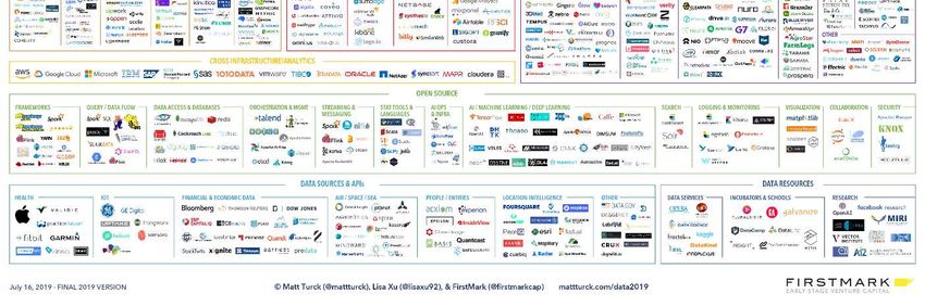
Marinet2 – Report on remote access assessment and development

Deliverable 4.2 – Report on remote access assessment
                  and development

                   This project has received funding from the European Union’s
                   Horizon 2020 research and innovation programme under grant
                                     agreement number 731084.

                                                                       Page 1 of 26
Marinet2 – Report on remote access assessment and development

                                           Document Details
 Grant Agreement Number               731084
 Project Acronym                      MaRINET2
 Work Package                         WP4: Research Enabling Robustness Proving and Future Proofing
                                      of Offshore Renewable Energy Infrastructure
 Task(s)                              T4.4: Electrical subsystems & grid integration: Innovating
                                      practices for improving the accuracy of infrastructure testing and
                                      remote access
 Deliverable                          D4.2
 Title                                Report on remote access assessment and development
 Authors                              François-Xavier Faÿ, Eider Robles (Tecnalia), Dónal Murray
                                      (UCC MaREI)
 File name                            D4.2 - Report on remote access assessment and development v1
 Delivery date                        20/12/2019
 Dissemination level
 Keywords                             Remote Access, Electrical Testing, Hardware in the Loop

                                      Document Approval Record
                                     Name                                Date
 Prepared by                         François-Xavier Faÿ                 15/10/2019
 Checked by                          Eider Robles                        31/10/2019
 Checked by                          Stephanie Ordoñez                   02/12/2019
 Approved by                         Eider Robles                        16/12/2019

                                      Document Changes Record
 Revision       Date            Sections Changed     Reason for Change
 Number

Disclaimer
The content of this publication reflects the views of the Authors and not necessarily those of the European
Union. No warranty of any kind is made in regards to this material.

                                                                                                 Page 2 of 26
Marinet2 – Report on remote access assessment and development

       Executive summary

The present deliverable reports on the specificity of remote access testing in dry electrical laboratories for the
development of ocean energy devices.
The user needs are presented and requirements for remote access are analysed. An assessment is made on the
existing capabilities for remote access testing using the main electrical infrastructures available through
MaRINET2 institutions. A global framework is proposed to enable this functionality taking into account IT
(Information Technology) access issues, data collection and safety.
The main outcome of this report is to detail the considerations and work required in order to turn an electrical
test infrastructure into a remote access platform.
A case study is proposed to apply the specifications described in the document with one of the partners’
infrastructure. It follows the methodology described in this deliverable, and the remote access was recorded.
The edited video is uploaded to a public repository as a proof of the successful test.

                                                                                                    Page 3 of 26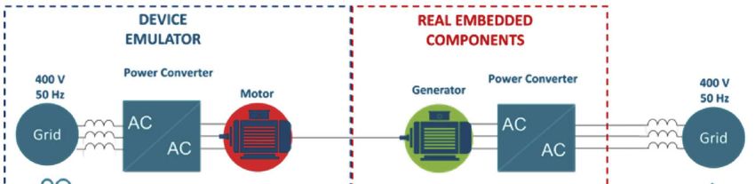
Marinet2 – Report on remote access assessment and development

Table of Contents
Executive summary............................................................................................................................................ 3
Table of Contents ............................................................................................................................................... 4
     Terminology .................................................................................................................................................. 5
1.      Introduction ............................................................................................................................................... 6
2.      Remote access testing to enhance infrastructures’ capabilities ................................................................. 8
     2.1        Motivation for remote access testing ................................................................................................ 8
     2.2        User needs ......................................................................................................................................... 8
     2.3        Remote access requirements and partners’ capability ..................................................................... 11
     2.4        Risk assessment............................................................................................................................... 11
3.      Proposed framework for remote access testing ....................................................................................... 14
     3.1        Global infrastructure framework ..................................................................................................... 14
     3.2        Test procedure for remote access testing ........................................................................................ 17
4.      Case study: Step-by-step guide for remote access on Tecnalia PTO test lab .......................................... 19
     4.1        Preparation for a remote test ........................................................................................................... 19
     4.2        Running a remote test batch ............................................................................................................ 21
     4.3        Lessons learned ............................................................................................................................... 22
5.      Concluding remarks and future works..................................................................................................... 23
6.      Bibliography ............................................................................................................................................ 24

                                                                                                                                                   Page 4 of 26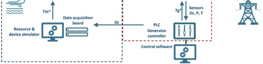
Marinet2 – Report on remote access assessment and development

Terminology
Abbreviations and acronyms
DB      Database
(P)-HIL (Power) Hardware-In-the-Loop
I/O     Inputs/Outputs
ICE     In Case of Emergency
IT      Information and Technology
LAN Local Area Network
OED Offshore Energy Device
ORE Offshore Renewable Energy
OWC Oscillating Water Column
PTO Power Take Off
RT      Real-Time
SCADA           Supervisory Control and Data Acquisition
TNA Transnational Access
TRL Technology Readiness Levels
VHF Very High Frequency
VOIP Voice Over IP
VPN Virtual Private Network
W2W Wave-to-Wire
WEC Wave Energy Converter
WFS Water Free Surface

                                                                                          Page 5 of 26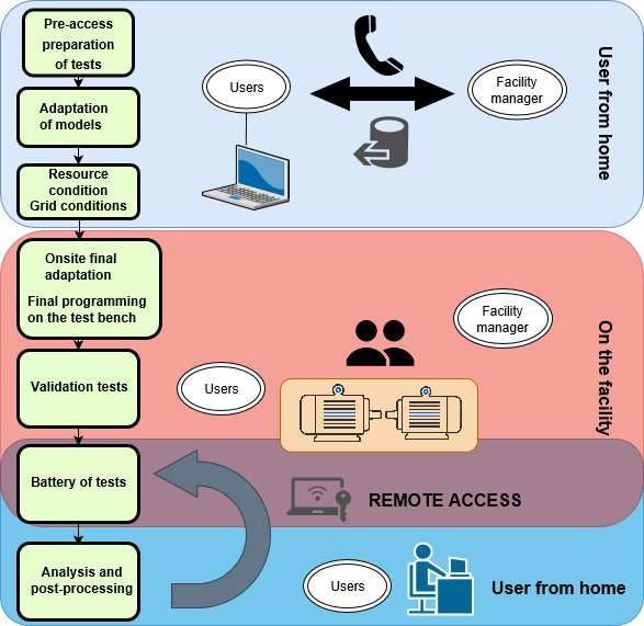
Marinet2 – Report on remote access assessment and development

1. Introduction

From the proof of concept of an idea to the industrial roll-out of a product, there are a series of important steps
to carry out where the Research and Development (R&D) activities are continuously on-going. The TRL
approach (Technology Readiness Levels) sums up the development life of a technology and details the various
phases such as the prototype, demonstration and pre-commercial ones.

Along the technology development pathway, there is a need to validate some characteristics in order to reach
the next TRL, keeping in mind the economic viability and the environmental and social aspects of the
innovations at each step. As technology developers are advancing in the prototyping phase, they will validate
certain aspects related to the capture of energy via testing at scale like a test campaign in wave basins for Wave
Energy Converters. The PTO (Power Take-Off) components and their associated controllers are then tested in
dry laboratories before being tested in the prototype at sea. In the framework of the MaRINET2 project,
infrastructures are accessible free of charge to foster the development of ORE devices (Offshore Renewable
Energy) including wave, tidal and offshore wind technologies to advance to higher TRL. Among them,
electrical infrastructures allow the testing of several aspects of the power conversion such as: some components
that constitute the drive train, the control unit and the control algorithms, the SCADA (Supervisory Control
and Data Acquisition) system and issues related to the power integration to the electrical grid. The validation
of these aspects in a lab corresponds to TRL4 and is the prior step before validating the technology in a relevant
environment integrated in a prototype.
The term electrical test infrastructure refers to any type of facility which allows the testing of electrical aspects
of the power conversion from an ORE converter. Most of the time they are based on a Hardware-In-the-Loop
(HIL) framework that consists of feeding back the modelled experiment with real measurements from the test
rig and which has to adapt its response in consequence. These electrical test facilities can include:
    -    Electrical PTO laboratories
    -    MicroGrid
    -    Modelling computers, some of which with real time modelling capabilities and various I/O
    -    Motor to generator coupled test rigs, where the motor can emulate a turbine
    -    Advanced power converters to control machines or power flows to the grids/microgrids
During the FP7 MaRINET project, best practices were drawn up for the use of electrical infrastructures for
PTO testing [1]. From past experiences based on research groups performing controller testing, the use of dry
test laboratories is not obvious although it follows a certain procedure. Typically, a test campaign requires a
number of activities:
    -    Defining a test plan: the definition of a clear and realistic test plan is required before heading to the
         facility, in agreement with the infrastructure owner.
    -    Prior to the test: The experiment setup includes the model adaptation to fit the infrastructure
         specificities (I/O, data acquisition, etc), and the selection and implementation of a scaling
         methodology for the physical quantities to meet the prototype and the test bench scales.
    -    During the test: The testing phase respecting the test plan, develop patches to correct bugs.
    -    After the test: Data post processing, data analysis and reporting.
All of these activities are quite time consuming and it is usually not uncommon to witness alterations in
elaborated test campaigns, to accommodate the replication of some tests or to dismiss some of them due to
time restrictions. . Enabling remote access capability to an infrastructure can ease the work of research groups
in many testing phases, especially before testing where the test bench is not even powered on and after the test
campaign when the infrastructure potential is fully understood.

                                                                                                       Page 6 of 26
Marinet2 – Report on remote access assessment and development

Whether remote access capability may enable the ease of work along the development phases of ORE devices,
its applicability may be restricted to particular components. In the Marinet 2 project, the electrical connection
particularities of a device have been identified as ideal to be tested through remote access.
The scope of this report is to detail the development of remote access in electrical infrastructures by first
detailing the needs from the user perspective, establishing the current state of remote access capabilities among
network partners and identifying suitable laboratory installations as shown in Section 2. A methodology for
remote access implementation is presented in Section 3 and applied in Section 4 where a case study in one of
the partner’s installations is performed.

                                                                                                   Page 7 of 26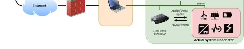
Marinet2 – Report on remote access assessment and development

2. Remote access testing to enhance infrastructures’
   capabilities

2.1      Motivation for remote access testing
Remote access testing is proposed as a new route to pre-test ORE equipment. This brings several advantages
such as reduction of complexity and costs; however, is it possible and safe to do remote access testing in this
type of facilities? In practice, D4.2 of the MaRINET FP7 Project [2] showed that despite the importance of the
control and grid connection of ORE devices, the requests for testing at electrical facilities were not very
successful among MaRINET applicants which evidences that the devices are still not at this development stage.
For example, a common practice of the onshore wind turbine sector is to test the controls and grid connection
algorithms in small scale electrical facilities, as in this case, power capture design is not in question anymore.
However, most of the tests being performed in the ocean energy areas are related to the testing of the physical
prototypes, with the main objective being validating a determined concept. In many cases, the research and
subsequent tests of the generator, power electronics and grid connection part are overlooked at low TRLs. This
oversight may implicate a device failure at larger stages of development and therefore, projects like MaRINET
and MaRINET 2 also intend tohighlight the importance of testing the electrical part.
It is expected that these tests will become essential in the near future, when the technology of the devices will
not be so questioned, and their control and grid connection will become the new challenge. Finding a gap of
several-weeks for developing and carrying out a test campaign dedicated to electrical matters is difficult and
therefore, in most of the cases, these research projects end with only simulated results. Remote testing would
definitely facilitate the experimental validation of these projects time and cost effectively. It is envisage that
its use will also enhance collaborations between research groups leading to collaborative projects and
publications.
These kinds of facility owners usually also come from the research environment. They perform their own
research on the facility, but it is underused if no external user come. So, the motivation also comes from the
facility owner’s perspective. Remote access capability would benefit the owner in two ways:

Economic: Users would save time and money regarding transport and accommodation but would instead pay
a test bench use fee.

Collaboration: Contacts and preliminary tests with other research groups may lead to further research
collaborations, future projects, publications, etc.
In addition, the ORE industry would benefit from the improvements due to experimental validation of
numerical simulations developed by diverse research groups, as they are progressing on technical issues that
will need solutions in the near future.

2.2      User needs
Past experience gathered from the use of electric test rigs revealed the users needed at least two visits to the
test infrastructures to complete a full test campaign: one to understand the test bench specifics and adapt the
numerical models and another to perform the experiments. A test campaign in an electrical infrastructure is a
long procedural activity where the main tasks are usually [2]:

    •   Pre-access preparation of the tests. Before accessing the infrastructure, discussions with the
        infrastructure provider are required in order to obtain all the inputs needed to perform the tests.

                                                                                                    Page 8 of 26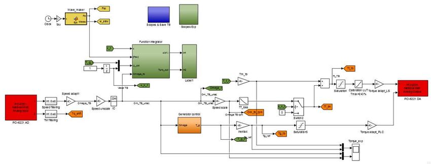
Marinet2 – Report on remote access assessment and development
• Adaptation of models: The mathematical models that represent the resource and the energy converter
behaviour have to be adapted to the electrical facility. Each facility may have a different simulation
software and I/O acquisition boards. Usually users start at their institution, but this work needs to be
finalised at the facility.
• Load and grid profiles: Discussion about the appropriate sea-state conditions to be tested. Prepare a
detailed and realistic test plan with the infrastructure manager.
• Onsite preparation of tests: Final programming of the devices in the lab. Final programming of the
proposed controls. Understand the specificities and adapt the numerical models - typically one week
– requires a high level of support from the facility manager
o Validation tests: Initial tests to analyse the performance of the facility with the device are
undertaken.
The initial tests do not consider grid connection and generic controls can be used at
this stage to perform general tests of the device.
Full tests: Once the device simulator’s behaviour represents completely the
behaviour of the mathematical models and/or the results of prior tests in the tank, the
proposed controls can be tested.
• Battery of tests: typically, one week – requires only supervision while the tests are ongoing.
• Analysis and post-processing: Data post-processing, analysis, and report of the main outcomes.
Figure 1 shows a diagram with the typical steps needed for completing a test campaign in an electrical test
bench facility by external users. As shown in the diagram, the tasks can be divided into 3 groups:
- Pre-access at users’ institution: the user and the facility manager must keep in contact. The facility
manager is responsible for providing the information necessary to the potential users.
- On site tasks: Initially the users and the facility manager will work together until the models are
completely adapted to the facility particularities and validated. Then the test batches can be undertaken
by the user almost independently. Sometimes, adapting the model to the facility is a long process and
it is a common practice that the return to the facility at a later time to fulfil the test campaign.
- Post-access: The users need to analyse and process the information gathered during the test campaign.
This processing is a feedback of the initial research and can lead to new alternatives or variations in
respect of the previous work. In many cases, users need to go back to the facility to test the new
findings that are derived from the new research developed after the test campaign.
Page 9 of 26Marinet2 – Report on remote access assessment and development
Figure 1. Steps for a testing campaign in an electrical test bench facility
Several research groups accessed TECNALIA’s PTO test lab in the framework of MaRINET FP7. Each visit
led to post access reports and most of them are reported by Armstrong in [3], amongst them, the following
projects are of relevance:
- Med. Univ Reggio Calabria: REWELPO
- Univ. Parma and Padova: MORE 1 & MORE 2
- IST-IDMEC: SPOWCON adaptive CLs comparison followed by PreCONTurb MPC
- IST-CENTEC: GenPTO
Two additional projects from the universities of Parma and Padova and two projects from the IST-IDMEC
group took place during two different calls from the FP7 Marinet Transnational Access. These examples
revealed the necessity to return to the facility with additional objectives requiring a new test campaign.
Enabling remote access testing to the infrastructure could save up at least a visit per campaign once the test rig
specifics are fully understood and the models are running as expected. This could reduce the associated
economical costs, environmental impact (CO2 emissions of transportation) and practicalities of the visits
(availability of all interested parties). Thus, remote access capability brings to the users’ additional flexibility
Page 10 of 26Marinet2 – Report on remote access assessment and development
and further stimulates the use of electrical infrastructures while ensuring strong international collaboration
between centres, which is the main philosophy of the MaRINET programs.
Furthermore, the described one or two-week test campaign enables experimental testing/validation of one
project in a specific moment of the research. As represented in Figure 1, the analysis of experimental data after
the access leads to a better understanding of the technology and creates opportunities to improve it. These can
be included for another set of tests when new solutions and ideas may arise. Remote access would facilitate
the real completion of a project because once the facility and models are prepared, small changes can be done
remotely, relatively quickly and at a reduced cost.
2.3 Remote access requirements and partners’ capability
In terms of the requirements for remote access development, the first is that the infrastructure needs to be safe
to use both for people working around the test rig and in the facility itself. The risks related to IT (Information
Technology) matters also need to be minimised; e.g.network attacks, but they do not represent a technological
barrier.. Remote access capabilities would depend on the facility, but hopefully, all the terminals used to
control the test rig’s physical power equipment (computers, control units) can be configured as part of the
same network (local network or infrastructure network). In a dry test laboratory, the system can be run
automatically, but keeping in mind that other users, researchers and technicians can work around the rig.
Therefore, remote access requirements must follow the measures to provide optimum personal safety and these
are usually established by the institution or else might need to be developed in the institution for this remote
access scenario.
Partners’ capabilities to do remote access testing have been compiled and summarised in Appendix A.
When an infrastructure manager enables remote access to the facility, a new service is created which improves
the attractiveness of its test infrastructure. Different levels of engagement from the users are also devised
during the campaign; from the definition of the test program, its implementation, test campaign and the data
processing. In the end, the two parties are to find a good balance between the level of autonomy for the user
and the commitment from the infrastructure’s side.
Furthermore, technology developers having tested their prototypes at sea have used similar frameworks to
access remotely the control units but with more demanding specifications such as assuring a safe internet
connection with redundant medium (fibre optics, 4G, VHF, …). During the H2020 OPERA project [4], two
sea trial campaigns took place to test technologies in real environments: one using the Mutriku OWC plant,
and the other in the MARMOK-A-5 buoy from IDOM. In each case, after a commissioning on site, the
supervision was done remotely by accessing a master computer (centralising the connections to the control
unit, SCADA and databases) that made the bridge connection between the office and the plant network
infrastructure. Experience gained during the project is reported in the deliverable D1.1 from WP1 about Data
Collection [5].
2.4 Risk assessment
Each facility possesses its own internal regulations that are mostly focused on safety issues. Remote access is
not usually contemplated in these regulations. This is a critical matter as risks involved with remote access
need to be studied in terms of:
- Personnel
- Equipment
- Data
This section will provide a general safety guidance analysing the risks associated with the remote access testing
and safety measures to lower them.
Page 11 of 26Marinet2 – Report on remote access assessment and development
2.4.1 Personal safety
Electrical test rigs count on moving parts and electrical equipment with live voltages. In the event that a test
facility is being operated remotely, and no technician is needed for support, the test area remains physically
unattended and a security area must be established. This security area should be clearly delimited with fences,
red-white safety chains, warning signs and interlocks to prevent someone entering the zone and cutting off
power and removing risks if the delimited area is entered. The best option being that the test rig is isolated in
a separate room.
If the rig is controlled remotely, but a technician remains present during the test batch for providing support
when necessary, a control light can be used at the remote user connection to warn when the test is being carried
out. Again, an interlocked system should be used that will cut power to the rig if a danger zone is entered
during testing, to minimise the risk of human error contributing to an accident.
2.4.2 Equipment safety
When a facility is going to be remotely operated maintenance and calibration is especially important and can
be considered as the first preventive measure. Remote users cannot realise if screws are loosening, electrical
cables are damaged, or sensors are not well calibrated. Therefore, a good maintenance and calibration plan
with extra precautions is mandatory.
Equipment safety measures contribute to personal safety as well.
Other safety measures to be taken into account are the following:
- Sensing and monitoring: test rigs are already equipped with sensors collecting the data from the main
variables that interfere in the process. These values are especially important in remote access where
remote users cannot experience the behaviour of the facility. A detailed list of available variables,
nominal and maximum values must be reported. In some cases, additional sensors must be installed
in order to avoid operation outside the limits of the facility. Critical variables regarding safety must
be identified and thresholds defined.
All variables must be collected and remotely monitored.
- Alarms: If any of the monitored variables goes out of its range, remote users must be warned by means
of an alarm. In addition, an audible alarm must be incorporated in the facility to warn workers around
that the test rig that this has exceeded the operating range.
- Automatic safety shutdown: a controlled shutdown must be programmed. If identified critical
variables exceed their limits, the test rig must be prepared for an automatic safety shutdown.
- Remote secure stop: all the facilities rely on emergency stop buttons that can be activated onsite in
any uncontrolled event. Despite all the extra safety measures, remote access must be prepared for an
uncontrolled situation with a “virtual emergency stop button” that remote users can activate it to force
the test rig to a safety shutdown.
- Camera: A webcam installed on the security area will help remote users to observe the test rig during
operation.
- ICE contact: the test rig must include a telephone and sign with the ICE number (112 in Europe)
- Each facility has its own particularities and thus, its own safety measures. These must be analysed
and adapted to the remote access situation
Page 12 of 26Marinet2 – Report on remote access assessment and development
2.4.3 Cybersecurity
Cybersecurity is the practice of protecting systems, networks, and programs from digital attacks. Nowadays,
there are multiple types of cybersecurity threats, and thus, this is a new market with emerging companies
proposing several solutions.
Dealing with cybersecurity is out of the scope of this report. However, possible threats must be taken into
account and prevention measures taken in consultation with the IT department within each facility. The main
vulnerabilities related to remote access capability are the following:
- Unauthorised physical use of the test rig: this is the main problem that must be tackled. This risk has
to be evaluated by each infrastructure manager, within its organisation’s IT security policies as
mentioned in 3.1.1
- Data confidentiality: every experimental data will end in a repository from where the users can
download and perform data post processing routines. Sharing data is not a particularity of remote
access, as it can be done within the premises (in a physical manner) and each organization already has
the means to prevent the theft of data.
Page 13 of 26Marinet2 – Report on remote access assessment and development
3. Proposed framework for remote access testing
Any electrical test infrastructure allows technology developers to work on aspects related to the electrical
power conversion unit of the device and to assess the performance and grid connection issues. The actual
system under test can include physical components such as the generator, the power converters, the control
unit, the SCADA; but also the control algorithms to optimise the power production and improve power quality
for grid integration. The electrical system usually presents a real part to be tested and an emulated part that
reproduces the behaviour of the device. Any dry test laboratory could develop its remote access capability for
its HIL or PHIL laboratory. On the one hand, this section details the various blocks that constitute the HIL
infrastructure and how this one is integrated into a remote access framework. On the other hand, a test
procedure and recommendations are proposed detailing the steps that the user should follow to perform a test
remotely.
3.1 Global infrastructure framework
The schematic view of Figure 2 presents the different systems involved in an infrastructure prepared for remote
access testing. It details the various blocks from the remote user to the electrical infrastructure from an IT
network perspective. Each stage is detailed in the following sections.
Figure 2. Network infrastructure for remote access testing
3.1.1 Network and IT infrastructure
The remote user is connected to the internet using a public domain address. In order to access the facility, the
user enters the private infrastructure network by connecting to the test rig workstation via a secured connection.
The technologies to securely remote to a private Local Area Network (LAN) are based on VPN, which stands
for Virtual Private Network. They use tunnelling protocols to encrypt/decrypt data at the sending/receiving
end. A user has to be authenticated to use that service (password, temporary security token, biometric data). It
is a commonly used technology in IT companies but can have security limitations because it presents the risk
of bringing malware into the private network, or attackers can connect the infrastructure with stolen
credentials. This risk has to be evaluated by the infrastructure manager, with its organisation’s IT security
policies. Several data encryption protocols can be used to secure the remote connection, these include:
- IP security (IPsec)
- SSL, Secure Sockets Layer and TLS, Transport Layer Security
- PPTP, Point-To-Point Tunnelling Protocol
- L2TP, Layer 2 Tunnelling Protocol
Page 14 of 26Marinet2 – Report on remote access assessment and development
- OpenVPN
On the user’s side, it is required that the endpoint device runs a VPN client to actually create the VPN tunnel.
There are numerous software applications that permit to remotely access other computers. Although they all
provide the same basic service for remote access, they show differences in terms of functionalities (cloud based
or locally installed applications, file transfer, chat, VOIP, …), and the licencing types. The most common
platform is the Windows Remote Desktop Connection as it is available in any Windows OS machine; however,
below is a list of other client applications:
- TeamViewer - Screenleap
- LogMeIn - Zoho Assist
- Remote Desktop Connection - Remote Access Plus
- Chrome Remote Desktop - Remote Desktop Manager
- Remote Utilities - VNC Connect
- dualmon - REMOTE PC
- Screens - GoToMyPC
- UltraViewer - LiteManager
- ThinLinc
Once connected to the workstation, the remote user can operate the test rig as if physically present in the
facility. In the example presented in Figure 2, the workstation is the master PC connected to the local ethernet
network where the different pieces of equipment are part of the same physical network, using a hub or rooter,
and part of the same network domain.
Recommendations are to set the acceptable levels of cybersecurity requirements to face the risk that constitutes
external threats as described in Section 2.4.3. Each infrastructures must introduce its own IT safety policy to
establish a secured connection to external hosts, this issue is out of the scope of this report.
3.1.2 Workstation
The test rig workstation is the gateway to access the test rig components that are connected to the laboratory
LAN. This one hosts the pieces of software that operate, configure, control and program them. They allow
code generation, compilation of algorithm’s source code for the Real-Time (RT) simulator for the emulated
part and for the control unit. Finally, this station is the one dedicated to start/stop the RT experiment and
provides the user with a visualisation of the state of the components and the experimental measurement data.
3.1.3 Real-time simulator
The RT simulator is the interface between the simulation and the real experiment under test. On one side it is
linked to the workstation where the numerical models are developed to run the simulation, and the other side
embeds the hardware responsible to process in RT the analogue/digital I/O with the actual system under test.
The models are mainly developed in engineering software such as Matlab/Simulink or LabView, which
includes the associated I/O blocks to the simulator signals. They are then built and sent from the workstation
to the simulator that processes the RT program and all the I/O signals. In [6], Ibarra, et. al., showed an overview
of the available real-time simulation systems mostly used for HIL and PHIL application, and these are
summarised in Table 1. Different types of real-time simulators, taken from [6]
Page 15 of 26Marinet2 – Report on remote access assessment and development
Table 1. Different types of real-time simulators, taken from [6]
3.1.4 Physical test bench
The actual system under test is the physical component of the test bench. These components can include the
drive train parts of the ORE device production unit, PLC, SCADA, power converters, batteries, and grid
connection equipment. Not only can the test bench test and assess the various blocks constituting the power
conversion, but also the control algorithms to operate the ORE device in a safe and efficient manner. Each part
of the actual technology to be tested is either reachable by the workstation by ethernet, or a serial port, or
through the RT simulator. In the vast majority of the cases, several items of equipment have to be manually
switched ON/OFF or have manual selectors to activate/deactivate certain modes of functionality. Then
infrastructure operator has to be physically present to carry out the boot up procedure before being used by a
remote user. Also, this person has to be present or easily reachable in case of any eventuality (loss of internet
connection, motor overspeed, …). At operations close to defined safe limits, the test rig should have security
measures and a strong fault management system in order to operate the equipment within the design range. If
a physical quantity overshoots the equipment thresholds, automatic and controllable breakers should be
activated. These would automatically open the electrical circuit for the equipment experiencing an undesired
or uncontrolled operation.
3.1.5 Data acquisition, hosting and processing
When thinking of testing in any infrastructure, the issue of high quality experimental data collection and access
is of paramount importance. The data flow from the measurement sensors can be rooted either to different
places or centralised in a platform such as a SCADA, the second would be the more suitable option to avoid
complicating data capture and data synchronisation issues. The possibilities brought by data infrastructure
technologies relying on database (DB) management systems are quite appropriate for centralising and hosting
both measured operational data and processed data. A good practice can be to centralise all experimental data
to the SCADA which can store them in a local DB. The local DB can be replicated online in a cloud
infrastructure. In that way it is physically present in the infrastructure for data safe storage, and available on-
line for easy consultation/processing by the remote user. The way the data are accessed and stored should be
subjected to a contractual data management plan dealing confidentiality issues, storage management and data
access.
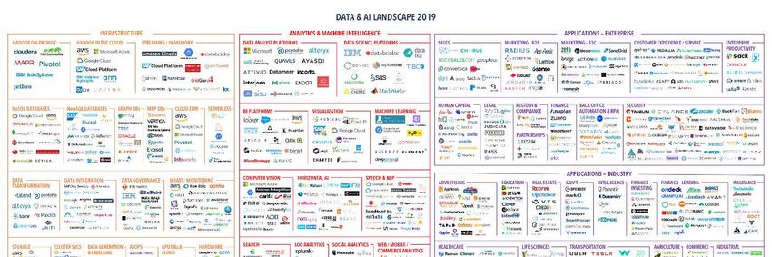
With the technology boom of Big Data, the opportunities offered by this new paradigm in managing the
quantity of data are wide. Figure 3 presents a global map of the Big Data environment including data
Page 16 of 26Marinet2 – Report on remote access assessment and development
infrastructure and management, data analytics and related applications. One can imagine during the test, the
experimental data generated by the use of the infrastructure can be replicated to a cloud-based web platform
providing aggregated services such as:
- data storage for fast access to raw data
- RT processing through data analytics
- RT graphical view of data flow
- development of models and applications such as digital twins to improve performance and reliability
of the system under test
Figure 3. Big Data Landscape 2019 seen in [7]
3.2 Test procedure for remote access testing
In this section, a test protocol is proposed to both the remote user and the infrastructure manager, which
describes the steps one should follow to remotely run an experiment.
1-Remote connection to the test rig workstation
The first step is to deal with the remote access on the test rig workstation. As stated above there are many ways
to create a secure VPN using the Windows desktop software or third-party programs. In the first case, the
recommendation is to contact the IT support to grant access to a specific location, having its public IP address,
and grant the access to the rig computer. The user will remotely connect to the test rig PC by entering the IP
address provided by the IT administrator. For each user group, a remote user account should be created on the
workstation with the appropriate user rights to ensure confidentiality of data such as the type of account:
standard or guest use; and the specification of folder and software access rights.
2-Understand the test rig specificities
Each facility manager should provide clear information about the infrastructure and should include:
Page 17 of 26Marinet2 – Report on remote access assessment and development
- Detailed list of equipment and operation ranges (nominal and extreme)
- A list of all the I/O signals to communicate with the equipment and their characteristics
(analogue/digital voltage or current and range)
- A dummy numerical model to be used in the experiment with a generic Wave-to-Wire (W2W) model
and control black boxes which already include the I/O to communicate with the hardware of the
physical equipment as well as the appropriate prototype-test rig scaling methodology (Froude, Mach,
Reynolds, …).
- A step-by-step user guide including:
o The boot-up sequence with all the equipment software
o The actual test run
o The safe stop sequence
o The emergency stop sequence
- Learn how to use the test bench by running the infrastructure base experiment. Communication
between the remote user and the facility supervisor is required at this stage.
3-Adapt the numerical model with the user project and test it
- Replace the black boxes and initialisation scripts with the user project
- Run a simulation (no test rig) to ensure the inexistence of software bugs
- When the model is set, follow the step-by-step guide to run the project experiment. Communication
between the remote user and the facility supervisor is also required at this stage.
4-Data analysis
- Collect/access the centralised data
- Post process and analyse the data
- Re-run tests if needed
- Report
Page 18 of 26Marinet2 – Report on remote access assessment and development
4. Case study: Step-by-step guide for remote access on
Tecnalia PTO test lab
The aim of the case study detailed in this section is to perform a remote access testing to the Tecnalia PTO test
lab from UCC offices. The procedures developed in the deliverable will be followed for this test. The objective
of this experiment is to briefly compare two control algorithms for an OWC (Oscillating Water Column)
device.
4.1 Preparation for a remote test
4.1.1 Description of the experiment
The numerical model simulates one air chamber of the Mutriku OWC plant and the PTO includes a biradial
turbine of 0.5 m diameter and an induction generator of 30 kW nominal power. The model was developed
during the OPERA project and some algorithms were tested at Tecnalia and UCC as detailed in [8]. The
experiment to be run aims to understand the pros and cons of using a fixed speed controller and a variable
speed controller.
The W2W model was developed in the Matlab/Simulink environment as the test rig is based on an XPC target
configuration. It is composed of three main blocks:
- the Wave Maker: after selecting a sea state, defined by a significant wave height and a peak period
, it generates a series of irregular wave elevations and the resulting excitation force based on the
excitation response coefficient of the plant.
- the WEC, it describes all the dynamics of one chamber of the Mutriku plant and the PTO behaviour,
mainly:
o the motion of the internal water free surface inside the chamber
o the pressure variation as a function of the WFS and the turbine dynamics
o the air flow across the turbine
o the power, torque and efficiency of the turbine
o the power, torque and efficiency of the generator
- the control algorithms
Figure 4. W2W model used in the experiment
Page 19 of 26Marinet2 – Report on remote access assessment and development
4.1.2 Presentation of the PTO test lab
Figure 5. Schematic view of Tecnalia PTO test lab represents the general scheme of the Electrical PTO Lab in
Tecnalia. It is based on a HIL framework, the RT simulation model sends a reference to the test rig, the control
part implies a physical response in its behaviour which feeds back the model with real data. The test bed can
be divided into two key areas; the ORE device emulation and the generation unit. The ORE device emulation
part is composed of the motor, the frequency converter to control the motor, and the motor control software.
The aim of these components is to simulate the behaviour of the ORE device and the turbine under any sea
condition. It is a simulation because the mathematical equations are programmed in the motor control software
so it replicates the ORE converter dynamics. The generation area includes the generator, the frequency
converter to control the generator and a PLC with the generator control software. This part represents the real
equipment that could be connected between the ORE device and the grid. The motor and the generator are
directly coupled, and a flywheel is installed to add inertia. Note that both the electrical machines have the same
electrical characteristics that are shown in Table 2.
Figure 5. Schematic view of Tecnalia PTO test lab
Table 2. Characteristics of the PTO test rig
Rat. Power [kW] 15
Nom speed [rpm] 1460
Pole -pairs 32
Frequency [Hz] 50
Rat. Voltage [V] 400 triangle
4.1.3 Adaptation of the model to the test rig specificities
In order to perform the real time simulation and compare the control strategies, there are a series of adaptations
to be carried out in order to get a consistent connection between the HIL and the model to be tested. The first
scaling difference is the rating of the device at full scale versus the ratings of the test bench equipment; and
the second difference is because HIL testing has its own specificities.
As the PTO installed in the Mutriku plant does not match the ratings of the equipment composing the test rig,
a scaling method has to be employed. In this case, gravitational forces are critical so Froude scaling criterion
is used to maintain correct relationship between the prototype and the lab model. Also, because the ratings of
Page 20 of 26Marinet2 – Report on remote access assessment and development
the PTO system and the drive train of the test rig does not match, several adjustments are undertaken to fit all
the characteristics:
- Adjustment of the Speed: when the ranges of rotational speed between the model scale and the test
bench do not fit, the ratio of the nominal speeds from the test bench and the model-scale PTO is
calculated and relates both the instantaneous speeds.
- Torque adapters and inertia scaling: in order to match the test bench dynamics and emulate the effect
of inertia, the turbine torque sent to the motor is multiplied by a compensation factor taking into
account a ratio of inertias at various scales.
For more information on the scaling methodology used, the reader can refer to [9], [10]. In Figure 6 the
Simulink model for testing is plotted. The two blocks to connect to the test rig are in red, that is to say the
inputs and outputs of the analogue signals of the drive train rotational speed and the motor torque sent to the
drive, replicating the turbine behaviour. The numerical model is embedded in the green box where some
parameters were changed to better adapt to the test bench. Between these are the adapters described earlier due
to scaling considerations.
Figure 6. Simulink model with the W2W, the I/O of the test rig and the required adaptations
Now the model is ready to be compiled and downloaded on the Target PC which in this test rig represents
the RT Simulator.
4.2 Running a remote test batch
After agreeing on the test plan for this case study, a day of testing was scheduled between Tecnalia and UCC
through. François-Xavier Faÿ (FXF) and Dónal Murray (DM), respectively. The UCC researcher has never
visited Tecnalia’s lab, so this testing phase considered a time slot for explaining the equipment, their inter-
relation and their connections to the workstation. Tecnalia provided its HIL lab Step-by-step User Guide which
details the actions to follow for each software linked to the test rig components. The actual remote access test
began shortly after this training phase. The full test was recorded with several points of view – DM’s PC
screen, and video cameras from Tecnalia’s side – and an edited video covering the key steps of the test was
developed to show the success of the remote access test. Here is the link to the video:
https://www.youtube.com/watch?v=naKTHN3d2yE
Page 21 of 26Marinet2 – Report on remote access assessment and development
4.3 Lessons learned
Both researchers were always in communication through Skype and DM made a presentation with its screen.
This was essential from FXF’s side to ensure the steps were followed correctly and on DM’s side to hear the
effect of certain steps on the components and simply get feedback on the actions made. Some user
experience observations were taken during the remote testing:
- Video and audio were not ideal. This led to some issues; e.g. it was very useful to have someone from
the lab checking over the actions of the user, even when following a document (especially for the first
time when gaining trust in the manual). Seeing things on the Skype video is useful, but better
resolution can help understanding the facility. The Skype audio of the test centre cuts out background
noise and only transmits the sound when the person speaks. This background noise is useful to hear
when testing and it can be used as a parameter to envisage if the test is being carried out as planned,
as for example the fan of a drive, the electromagnetic noise from the electrical machines, etcetera.
- The expertise of the person present at the remote facility was important - familiarity with Skype,
Windows remote desktop as well as all the test software like Matlab/Simulink, TwinCAT, CTScope
and CTSoft was very important.
- Some issues encountered were related to the recording screen software, Skype software, remote
desktop software, and it can make it difficult for the remote user to seamlessly go between
devices/software to see things (or also accidentally open software when unintended). For example,
the Windows sizing bars can pop up and often overlap. Ideally seeing everything from the remote
desktop would be ideal (even having the video that was available through Skype here on this remote
computer would be better than the user’s own computer at their facility).
- The first test failed. FXF realised a signal wire was disconnected at the PLC’s side. This did not put
anyone nor any equipment at risk because the system was programmed to face this eventuality.
Although there can be several users of the test bench it is the manager’s responsibility to go on
through a check list to verify everything works as it is planned. It was essential to have a person
present at the test facility to error check the equipment.
- The rest of the test went as planned and the two control laws were tested.
- In case of a loss of internet connection from the remote user, the person in charge of the test at the
facility may be required to actuate and operate the bench to avoid having the test rig being
unsupervised. FXF took back the control of the workstation to simulate this type of incidence and
passed the test.
- As a recommendation it should be useful to install an IP camera watching the installation to have
visual and audio feedback on the on-going experiment.
Page 22 of 26Marinet2 – Report on remote access assessment and development
5. Concluding remarks and future works
This deliverable attempted to showcase remote access testing of electrical HIL and P-HIL infrastructures. The
report demonstrated the benefits attained when using remote access facilities from the remote user and the
facility manager perspective while introducing the potential risks associated with its use. On the one hand the
time saved by the user having such an infrastructure available online and the possibility for the facility to
increase its occupancy were brought forward. Making a facility remotely accessible was found to induce risks
which were listed and detailed (personal safety, component integrity, data confidentiality, IT threats, …). An
assessment of the remote access capabilities of the partners’ electrical infrastructures was also highlighted.
Recommendations were given to propose a framework for remote access testing including IT network
considerations and presenting the key components of the rig. A procedure was suggested with the main steps
to follow to remotely perform HIL testing. Then this procedure was applied in a case study where the electrical
PTO lab of Tecnalia was used by a researcher hosted at UCC MaREI. A video was recorded during the remote
testing to attest the test bench was operated remotely and this could reveal our experience of the experiment.
Finally, it can be concluded that remote testing can contribute to help technology developers to move forward
and test faster but this presents a series of challenges that the infrastructure has to meet when offering remote
access to its HIL test rig.
Page 23 of 26Marinet2 – Report on remote access assessment and development
6. Bibliography
[1] Eider Robles, Joseba Lopez-Mendia, and François-Xavier Faÿ, ‘FP7 MARINET - D2.11
Best practice manual for PTO testing’, 2015.
[2] Eider Robles, Salvador Ceballos, Joseba López, Imanol Touzón, Fernando Salcedo, ‘FP7
MaRINET-D4.2 Report on dynamic test procedures’. 2014.
[3] S. Armstrong, J. Rea, F.-X. Faÿ, and E. Robles, ‘Lessons learned using electrical research
test infrastructures to address the electrical challenges faced by ocean energy developers’,
Int. J. Mar. Energy, vol. 12, pp. 46–62, Dec. 2015, doi: 10.1016/j.ijome.2015.08.004.
[4] OPERA, ‘http://opera-h2020.eu/’, Open Sea Operating Experience to Reduce Wave
Energy Cost, 07-Sep-2018.
[5] E. Aldaiturriaga, O. Ajuria, T. Gordelier, J. Varandas, and J. Berque, ‘H2020 OPERA
D1.1 - Process Instrumentation Definition’, Jul. 2016.
[6] L. Ibarra, A. Rosales, P. Ponce, A. Molina, and R. Ayyanar, ‘Overview of Real-Time
Simulation as a Supporting Effort to Smart-Grid Attainment’, Energies, vol. 10, no. 6, p.
817, Jun. 2017, doi: 10.3390/en10060817.
[7] M. Turck, ‘Data & AI Landscape 2019’. [Online]. Available: http://mattturck.com/wp-
content/uploads/2019/07/2019_Matt_Turck_Big_Data_Landscape_Final_Fullsize.png.
[8] F.-X. Faÿ et al., ‘Comparative assessment of control strategies for the biradial turbine in
the Mutriku OWC plant’, Renew. Energy, vol. 146, pp. 2766–2784, Feb. 2020, doi:
10.1016/j.renene.2019.08.074.
[9] J. C. C. Henriques, L. M. C. Gato, A. F. O. Falcão, E. Robles, and F.-X. Faÿ, ‘Latching
control of a floating oscillating-water-column wave energy converter’, Renew. Energy,
vol. 90, pp. 229–241, May 2016, doi: 10.1016/j.renene.2015.12.065.
[10] F.-X. Faÿ, E. Robles, J. C. C. Henriques, and M. Marcos, ‘Best practices for the use of
electrical test infrastructures to validate control strategies: a case study in wave energy
conversion’, presented at the Renew 2016 2nd International Conference on Renewable
Energies Offshore, Lisbon, Portugal, 2016.
Page 24 of 26Marinet2 – Report on remote access assessment and development
Appendix A. Remote Access tes ng among MaRINET2
partners
Electrical facilities offered in MaRINET2 have particularities that make their usability and concerns regarding
remote access completely different. In addition, facility managers have gone through different experiences
when undertaking electrical testing. This appendix collects information about each facility’s current
capabilities and future perspective regarding remote access.
TECNALIA-Electrical PTO Lab
During the FP7 CORES project, there was a strong collaboration between UCC-MaREI and TECNALIA to
extensively test the electric power conversion part along with the SCADA. Also, 7 control laws were
implemented in the PLC code and were compared. The test rig was physically hosted at TECNALIA’s office
but could be operated by UCC to modify the code and launch some of the controllers’ tests. On that occasion,
remote access provided the flexibility required by this cooperative CORES project.
Thus, in TECNALIA’s PTO lab, the remote access capability had already been enabled. The only physical
operation is at the beginning of a test to switch on all the equipment. A control PC centralises all the software
to program/control the different equipment that constitutes the test bench (motor drives, frequency converter,
PLC unit).
SINTEF- Smart Grid Laboratory
The laboratory has flexible grid capabilities and different parts have to be manually connected and set up
before the experiment. Before Clients get access to the facilities, they have to get to know them and to undergo
a safety course. Tests are done onsite and with SINTEFs support.
SINTEF does not provide remote access option to external users as a standard package. However, in special
cases parts of the laboratory equipment, including Opal RT workstation, can be accessed remotely to perform
simulations. Due to safety and practical reasons, remote control of electrical equipment is not recommended
at the moment and not planned to be included as a standard package in the future.
ORE CATAPULT – eGrid
Status
Currently remote accessing the facilities of the ORE CATAPULT’s is not allowed. Someone from staff must
be present in the control room at all times performing the tests planned by the users; i.e. the user do not have
control over the test. In the case of eGrid, this can be controlled from 1 of 3 locations which is specified by a
Castell key. In the case of HIL, this can, in theory, be controlled from any PC connected to the network
provided they have the required privileges. If eGrid is turned on and the HIL testing mode is enabled, then the
HIL system will control the output of eGrid. The turning on and mode selection of eGrid however, can only
be controlled from the designated control room.
In terms of customers, the eGrid has the capability to allow customers to remotely connect into their device
under test if required within the 3 MW and 15 MW test facilities.
Page 25 of 26Marinet2 – Report on remote access assessment and development
Future plans
ORE Catapult do not plan on expanding remote access any further. The Castell key system is implemented to
prevent people from being able to control eGrid from unknown locations and accidentally or otherwise
interfere with an ongoing test. Similar systems are in place in all other facilities as a security measurement.
Relevance of offering Remote Access
Due to the nature of testing that ORE Catapult conducts, it has not often been necessary for customers to
procure remote access. The exceptions to this have been where software bugs have been discovered during
testing or faults requiring system resets have occurred within the customer’s test piece. In such cases, the
relevant technical personnel may not be on site. Having the ability to gain remote access to their system has
then been beneficial to allow test replications at a shorter time frames. This is rare however, as normally the
required technical personnel have been onsite.
ORE Catapult do not see any benefit in allowing remote access to the control of their facilities that outweighs
any safety concerns though. In any case, customers would not be able to “drive” the facilities during testing.
This would be done solely by their own trained operators in accordance with the agreed test plan.
UCC MaREI
The test facilities at UCC MaREI, including the Lir National Ocean Test Facility, have been undergoing
updated health and safety systems and policies in line with ISO17025 accreditation and with the university’s
own policies.
Until a complete investigation on all hazards and their proposed designed hazard eliminations for individual
remote access tests has been carried out, presented and agreed by the relevant authorities in the university, the
necessary actions will not be conducted. These procedures include the development ofrisk assessments and
method statements to run the tests but also the practices involving risk mitigation at work, as well as budget
identification, procurement process, supervision and validation of work carried out for these risk mitigations.
Currently there are renovation works on-going for other H2020 projects in the test centre to satisfy health and
safety testing requirements (but not for remote access testing).
The test centre has a variety of test rigs and test infrastructures, with different levels/types of network access
available. For example, some user PCs are only available on the facility local network, some are available on
the university network and some are not accessible in any network. IT issues have arisen in later years due to
the relatively large distance between the test centre and the rest of the university campus where the IT
department is situated but these are being improved at present.
Page 26 of 26You can also read