Space Shuttle Main Engine - The Relentless Pursuit of Improvement
←
→
Page content transcription
If your browser does not render page correctly, please read the page content below
Space Shuttle Main Engine —
                      The Relentless Pursuit of Improvement

                                           Katherine P. Van Hooser *   0F

                           NASA Marshall Space Flight Center, Huntsville, Alabama 35812

                                               Douglas P. Bradley †
                                                                  1F

                            Pratt & Whitney Rocketdyne, Canoga Park, California 91303

               The Space Shuttle Main Engine (SSME) is the only reusable large liquid rocket engine
           ever developed. The specific impulse delivered by the staged combustion cycle, substantially
           higher than previous rocket engines, minimized volume and weight for the integrated
           vehicle. The dual pre-burner configuration permitted precise mixture ratio and thrust
           control while the fully redundant controller and avionics provided a very high degree of
           system reliability and health diagnosis. The main engine controller design was the first
           rocket engine application to incorporate digital processing. The engine was required to
           operate at a high chamber pressure to minimize engine volume and weight. Power level
           throttling was required to minimize structural loads on the vehicle early in flight and
           acceleration levels on the crew late in ascent. Fatigue capability, strength, ease of assembly
           and disassembly, inspectability, and materials compatibility were all major considerations in
           achieving a fully reusable design. During the multi-decade program the design evolved
           substantially using a series of block upgrades. A number of materials and manufacturing
           challenges were encountered throughout SSME’s history. Significant development was
           required for the final configuration of the high pressure turbopumps. Fracture control was
           implemented to assess life limits of critical materials and components. Survival in the
           hydrogen environment required assessment of hydrogen embrittlement. Instrumentation
           systems were a challenge due to the harsh thermal and dynamic environments within the
           engine. Extensive inspection procedures were developed to assess the engine components
           between flights. The Space Shuttle Main Engine achieved a remarkable flight performance
           record. All flights were successful with only one mission requiring an ascent abort
           condition, which still resulted in an acceptable orbit and mission. This was achieved in large
           part via extensive ground testing to fully characterize performance and to establish
           acceptable life limits. During the program over a million seconds of accumulated test and
           flight time was achieved. Post flight inspection and assessment was a key part of assuring
           proper performance of the flight hardware. By the end of the program the predicted
           reliability had improved by a factor of four. These unique challenges, evolution of the
           design, and the resulting reliability will be discussed in this paper.

                                I. The Amazing Space Shuttle Main Engine
     The Space Shuttle Main Engine (SSME) was the only large reusable, liquid rocket engine in the world. It
operated at greater temperature extremes than any mechanical system in common use today. The SSME used as fuel
the second coldest liquid on Earth, liquid hydrogen at -423 degrees Fahrenheit. When the hydrogen burned with
liquid oxygen, the temperature in the engine's main combustion chamber reached +6000 degrees Fahrenheit, higher
than the boiling point of iron. The maximum equivalent horsepower developed by the three SSMEs used on every
Space Shuttle flight was just over 37 million horsepower, equivalent to the output of 13 Hoover Dams. Although
not much larger than an automobile engine, the SSME high-pressure fuel turbopump generates 70,000 horsepower
or 70 horsepower for each pound of its weight, while an automobile engine generated approximately one-half
horsepower for each pound of its weight. Even though the SSME weighed one-seventh as much as a locomotive
*
    NASA SSME Chief Engineer, NASA/MSFC/EE02
†
    Pratt & Whitney Rocketdyne SSME Chief Engineer, RAA50
                                                        1
                                American Institute of Aeronautics and Astronautics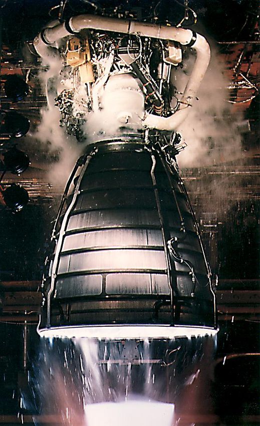
engine, its high-pressure fuel turbopump alone delivered as much horsepower as 28 locomotives, while its high-
pressure oxidizer turbopump delivered the equivalent horsepower for 11 more. SSME was the first engine with both
chamber pressure and mixture ratio close-loop control, with autonomous controller and health management, and
with variable throttling. SSMEs were the only large rocket engines in the world to achieve one million seconds of
operation consuming approximately 300 million gallons of propellant, and they operated safely and successfully on
all 135 Space Shuttle flights.
    The SSME was a staged-combustion cycle engine with a nominal burn time in flight of approximately 8.5
minutes at 104.5% of rated power level (RPL). A simplified SSME propellant flow schematic is shown in Figure 1.

Figure 1. Simplified SSME Propellant Flow Schematic

    As seen in Figure 1, liquid hydrogen entered the engine at the inlet to the Low Pressure Fuel Turbopump
(LPFTP). The LPFTP boosted the pressure of the fuel sufficiently to prevent cavitation of the High Pressure Fuel
Turbopump (HPFTP). The fuel flowed from the HPFTP pump discharge and split three ways. Part of the fuel was
used to cool the Main Combustion Chamber (MCC). This MCC coolant flow was then directed to the LPFTP,
where the then gaseous hydrogen powered the LPFTP turbine. After discharging from the turbine, the flow then
entered a coolant jacket around the engine powerhead. This then hot gaseous hydrogen eventually entered the main
injector for final engine combustion. The remainder of the pump discharge flow, after cooling the nozzle, mixed
with bypass flow and was directed to the preburners. The two preburners operated at a fuel-rich mixture ratio,
generating hot, hydrogen-rich steam to power the two high-pressure turbopump turbines. Following discharge from
the turbines, the hot gas was directed by the powerhead to the main injector for final combustion.2
    Liquid oxygen entered the engine at the inlet to the Low Pressure Oxidizer Turbopump (LPOTP) as seen in
Figure 1. The LPOTP boosted the pressure of the oxidizer sufficiently to prevent cavitation of the High Pressure
Oxidizer Turbopump (HPOTP). The HPOTP increased the oxidizer pressure, and the majority of the flow went
directly to the main injector for engine combustion. A portion of the HPOTP pump discharge flow was tapped off to
enter a boost pump at the end of the HPOTP and was used to provide oxidizer at even higher pressure to the
preburners. Another portion of the HPOTP pump discharge flow was tapped off to power the LPOTP hydraulic
turbine. The LPOTP turbine flow then merged with the main LPOTP discharge flow. 2
    The staged-combustion cycle yields both high efficiency and system complexity along with high turbopump
speeds and chamber pressures. The engine’s low-weight compact design and high efficiency lead to a world-class
                                                       2
                               American Institute of Aeronautics and Astronautics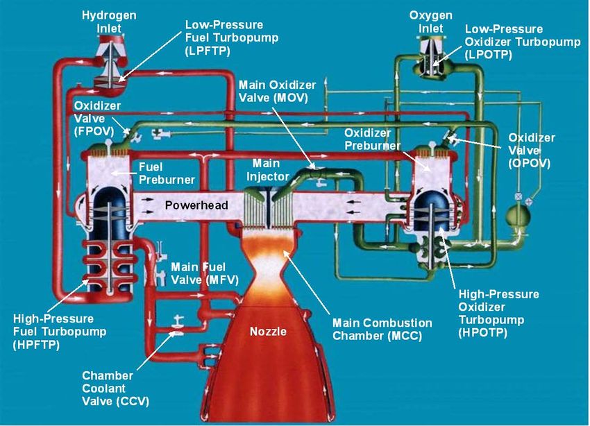
thrust-to-weight ratio of 66 at full power level. SSME performance parameters for the final engine configuration are
shown in Figure 2. Throttle requirements ranged from 67% RPL, during the time early in ascent when maximum
dynamic pressure was reached on the vehicle and again near Main Engine Cut-Off when the thrust was reduced to
maintain no more than a 3G acceleration, to 104.5% RPL at mainstage and 109% RPL for certain abort modes
(which were never implemented in flight). Figure 3 depicts a nominal mission profile. The control system
employed redundancy known as fail-op, fail safe which required the engines to operate normally for the first control
failure and then to shut down safely for the second failure.

                                                                        Propellants                                              O2/H2

                                                                        Rated power level (RPL)                             469,448 lb

                                                                        Nominal power level (104.5% RPL)                    490,847 lb

                                                                        Full power level (109% RPL)                         512,271 lb

                                                                        Chamber pressure (109% RPL)                         2,994 psia
                                                               14 ft

                                                                        Specific impulse at altitude                            452 sec

                                                                        Throttle range (% RPL)                                  67 to 109

                                                                        Gimbal range                                             +/- 11°

                                                                        Weight                                                  7,748 lb
                                                                                                                            55 flights
                                                                        Service life
                                                                                                                            27,000 sec

                                                                                                                           3,171 starts
                                                                        Total program hot-fire time
                                                                                                                          1,095,677 sec
                                         7.5 ft

 Figure 2. SSME Operational Characteristics

                                          Maximum Aerodynamic Pressure Throttling
 Percent Rated Power Level

                                                          104.5% Rated Power Level                         3G Throttle

                               Reusable Solid                                                 Main Engine
                               Rocket Booster                                                  Cut-Off
                                 Operation
                             6.6            120                                                          Plot is not to scale
                                                                   Time in seconds

Figure 3. Typical SSME Mission Profile

                                                                            3
                                                    American Institute of Aeronautics and Astronautics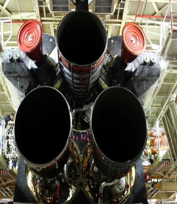
II. Design Evolution1,2,5
    The Space Shuttle Main Engine (SSME) was designed and developed by Pratt & Whitney Rocketdyne under
contract to the NASA Marshall Space Flight Center. The contract was awarded in 1971, and work on the engine
began in 1972. SSME engine-level testing commenced in 1975, and in the six years of development between the
start of testing and the first flight, numerous SSME hardware redesigns took place. These design-test-fail-fix
iterations are typical of any engine development program, especially within the context of development of a new
staged-combustion cycle, high thrust-to-weight, reusable liquid hydrogen engine. Solutions to the problems
depended on the severity of the issue. Redesigns were implemented as soon as possible for many of the problems
that were discovered, some issues could wait for resolution, and other problems were judged to be acceptable and
were managed with life or inspection limits.
    In the SSME 40-year history, all of the major components were modified and improved. Incremental, small
changes were certified based on analysis and/or limited hot-fire testing. More extensive changes were introduced in
“phase” and “block” changes in order to conduct flight certification test programs on several changes at the same
time, thus reducing test costs. The design features in each upgraded configuration are listed in Table 1 and will be
described below. Figure 4 provides a timeline showing when the major block improvements were incorporated.

Table 1. SSME Configuration Details
     First
                 Full Power Level
   Manned
                        or                              Phase II                      Block I         Block IA         Block IIA           Block II
   Orbital
                      Phase I
    Flight
  1st Flight:         1st Flight:                      1st Flight:                   1st Flight:      1st Flight:       1st Flight:       1st Flight:
    STS-1               STS-6                          STS-26R                        STS-70           STS-73            STS-89           STS-104
  4/12/1981           4/4/1983                         9/29/1988                     7/13/1995       10/20/1995         1/22/1998         7/12/2001
•Baseline       •Powerhead/Ducts            •HPFTP                                 •Phase II+     •Main Injector    •Large Throat        •HPFTP/AT
 Engine           − HGM fuel bowl liner       − Shot-peened fir trees               Powerhead      Modifications     MCC                 •Main Fuel
                    mods                      − Large coolant discharge orifices    (Two Duct)      − Programmed      − Cast              Valve
                  − Lox post support        •HPOTP                                 •Single Tube       secondary          Inlet/Outlet    •Non-integral
                    pins in FPB               − Bearing changes                     HEX               faceplate          Elbows           Spark Igniter
                  − New flow meter            − PBP damping seals                  •HPOTP/AT          coolant holes   − 20 -hole fuel
                    straightener              − Two-piece dampers                                                        sleeves         First Flight
                  − LOX post shields          − Non-scalloped interstage seal                                       •Block II LPOTP      STS-117:
                •HPFTP                          ring                               First Flight                     •Block II LPFTP      •Advanced
                  − Kel-F seals               − Tapered interstage seal            STS-75:                          •A-Cal software       Health
                  − Replaces stepped          − Thick PBP bearing isolator         •Thermocouples                   •Actuator spool       Management
                    interstage seals with       added thermal shield                                                 material             System
                    smooth                    − Bearing diametral clearances                                         improvement            − Real-time
                  − Increased clearance     •MCC                                                                    •Filtered check           vibration
                    turbine blade                                                                                    valves                   monitoring
                                              − EDNi reinforced outlet neck
                    clearance to tip seal     − Burst diaphragm drainline                                           •Pressure sensor
                •HPOTP                      •HPF Duct Helium Barrier                                                 improvements
                  − Housing material        •Avionics/Valves
                    changed (INCO 903)                                                                              First Flight
                                              − Increased strength MFV
                •LPFTP                                                                                              STS-96:
                                                housing
                  − Revised blocking                                                                                •Opened
                                              − Anti-backlash couplings
                    area                                                                                             boundary layer
                                              − Potted wireways
                •LPOTP                                                                                               coolant (BLC)
                                              − Tight stack GCV                                                      holes to minimize
                  − Turbine discharge         − Modified pressure sensor cavity
                    turning vane mod                                                                                 for faceplate
                                              − Improved hot-gas temperature                                         erosion
                •Avionics                       sensor
                •Nozzle                       − Spark igniter case structural
                  − Increased tube wall         improvements
                    thickness                 − 4k Hz monitor
                  − Added steam loop          − Skin temp sensor added to Anti-
                                                flood Valve

                                                                    4
                                            American Institute of Aeronautics and Astronautics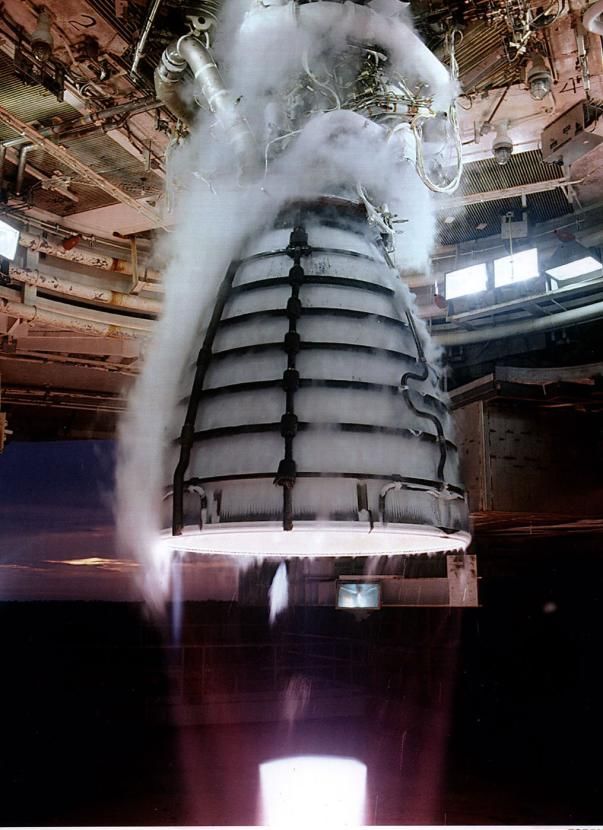
1970s                 1980s                1990s                2000s             2010s

                                                                                                  2011
                                       STS-1      STS-51L                            STS-107     STS-135
First Manned
Orbital Flight
                          1st Test   1st Flight

Full Power
Level
                                         1st Flight

Phase II
                                                      1st Flight

Block I/IA
                                                             1st Block I, IA Flights
                                                                              1st BII Flight
Block IIA/II
                                                                      1st BIIA Flight Health Management 1st Flight

Figure 4. SSME Configuration Timeline

A. First Manned Orbital Flight SSME
    The First Manned Orbital Flight (FMOF) configuration was the baseline SSME design for the first five flights of
the Space Shuttle. These first Shuttle flights were intended to be the checkout phase of Space Shuttle operations.
As such, engine power level was limited to 100% RPL, or 470,000 pounds vacuum thrust. The FMOF configuration
met safety requirements, but many of the components had limited operational life capability and had to be replaced
much sooner than the 55 flight requirement.

B. Full Power Level or Phase I SSME
    There was a possibility that payloads might exist that would require operation at Full Power Level (FPL), or
109% RPL, so within two years of the first flight, a Full Power Level or Phase I configuration was introduced into
the flight program. This configuration flew from STS-6 on
May 4, 1983 until the last flight of Challenger, STS-33 (51-
L) on January 28, 1986.
    One hundred forty-seven design changes to the FMOF
configuration were deemed necessary for FPL operation
including changes to the powerhead (Figure 5) and, perhaps
most significantly, to the four turbopumps. Changes were
made to the main injector to eliminate LOX post cracking,
and a steamloop was added to the nozzle feedline to
eliminate a failure mode from high strains during the engine
start transient. With the higher power level testing and
many changes being made in the design, many failures
occurred.
    While the hardware and system modifications were quite
successful at fixing many problems, several known failure
modes and technical vulnerabilities were not addressed with     Figure 5. SSME Powerhead, Main Combustion
the FMOF configuration.            Foremost among these         Chamber, and High Pressure Turbopumps
vulnerabilities were serious turbine blade cracks, sub-
synchronous vibration, bearing cage delamination, and ball wear on the HPOTP. At the conclusion of the FPL

                                                        5
                                American Institute of Aeronautics and Astronautics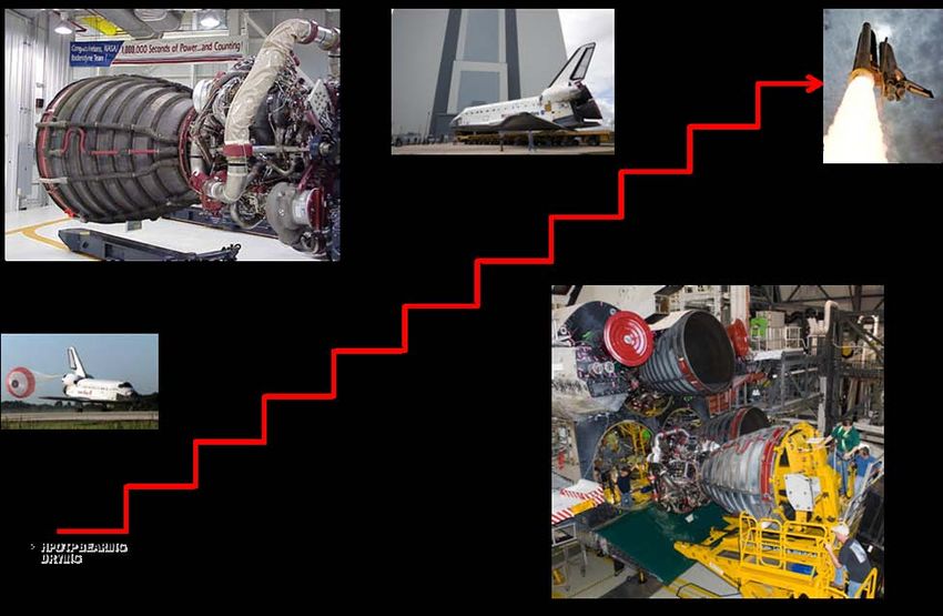
certification program, it was decided that sufficient margins still had not been obtained to allow flight at 109% RPL.
The program restricted engine operation in flight to 104% or less and put a long term plan in place to achieve the
higher operating power levels.1

C. Phase II SSME
     Following the 1986 Challenger disaster, the entire Space Shuttle Program was re-assessed. Profound changes in
SSME risk assessment and risk acceptance policies were implemented. As part of these changes, the SSME Failure
Modes and Effects Analysis/Critical Items List (FMEA/CIL) was completely rewritten. The new document was
more than 10 times longer than the original and identified 18 mandatory changes to the SSME hardware design, pre-
launch inspection requirements, and software prior to return to flight. In addition, an SSME Margin Improvement
Review Board identified 50 items as mandatory changes before returning to flight.1
    The Phase II configuration was flown on the return-to-flight mission STS-26R
on September 29, 1988. The new configuration included powerhead and duct
changes. Significant durability improvements to high pressure turbopump blades
and bearings were part of the redesign as well as a Block II main engine controller
(MEC) shown in Figure 6, not to be confused with the Block II engine configuration
to be described later.
    HPOTP bearing problems continued to persist. Additionally, the requirements
forcing extremely light weight high pressure turbomachinery made the housings,
shaft, and bearing systems insufficiently rigid to withstand internal failures meaning
that the turbopumps performed very well during nominal operations, but in the event
that something went wrong inside them, the failure would sometimes progress              Figure 6. Block II Main
rapidly to gross, uncontained turbopump and engine failure.                              Engine Controller

D. Block I/IA SSME
    The Block I SSME introduced several upgrades to the engine, improving reliability and safety. The Phase II+
powerhead was included in the Block I and IA engine configurations and implemented a two-duct fuel-side hot-gas
manifold which improved the high pressure fuel turbine discharge pressure distribution resulting in more uniform
introduction of hot-gas products to the main injector, thus improving performance. As part of the redesign effort, a
concerted effort was undertaken to improve the design to make it more producible. The redesigned powerhead had
52 fewer piece-parts and 74 fewer welds. The fabrication and assembly time was reduced by 40% and rework hours
were reduced by almost 50%.1
    A new single-tube heat exchanger (HEX) replaced the bifurcated configuration. The single-tube HEX
eliminated all seven criticality 1 (would cause loss of crew and vehicle if they failed) interpropellant welds. The
new HEX also had a significantly thicker wall, which made it much less susceptible to impact damage and less
vulnerable to through-wall wear at the bracket interface. Prior to the redesign, the HEX was assessed as the top risk
item on the SSME, primarily due to the number of critical welds, the extreme vulnerability of the thin walls, and the
very rapid progression from a HEX rupture to a loss-of-vehicle failure. The redesign very successfully mitigated
these concerns.
    Baffles in the main injector were removed, which resulted in an efficiency gain in the engine as well as a
producibility gain in the main injector. The baffles had been in place to damp out potential combustion instabilities,
but were proven to be unnecessary by main injector “bomb” testing conducted during engine ground tests on the
Technology Test Bed test facility at the Marshall Space Flight Center.

                                                        6
                                American Institute of Aeronautics and Astronautics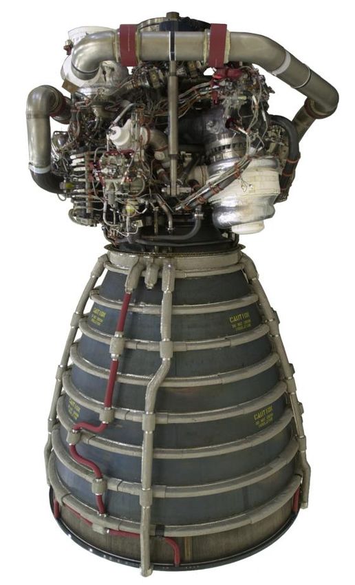
The Block I engine incorporated a completely new HPOTP
Figure 7. Block I High Pressure Oxidizer
                                                 designed under a separate contract with Pratt & Whitney in West
Turbopump
                                                 Palm Beach, Florida. This new turbopump was specifically
                                                 designed to eliminate critical failure modes and vulnerabilities in
the original HPOTP. A heavier allowable weight permitted a much stronger, stiffer rotor system, as well as more
robust pump and turbine housings, which made the turbopump much more tolerant to internal failures and off-
nominal conditions than the previous design. Advances in casting technologies permitted the incorporation of fine-
grained castings in the Block I HPOTP, which allowed the elimination of 293 welds within the turbopump,
including all 250 welds for which there was no rootside access for inspection at fabrication.1 Silicon nitride rolling
elements were used in the pump-end bearing virtually eliminating bearing wear and fatigue concerns. Also, the
turbopump was designed to use liquid hydrogen rather than liquid oxygen to cool the turbine-end bearing. Blade
cracks were essentially eliminated through the use of single-crystal alloy blades with thin-walled, hollow airfoils.
     The final Block I change was an upgrade to the SSME turbine discharge temperature sensors. These sensors
were extremely critical to engine operation and serve as one of the few active redlines during flight. The previous
design was a Resistance Temperature Device (RTD) sensor, and while it had a very fast response time, the RTD
sensor was very fragile and subject to fail during operation. In fact, the only in-flight SSME premature shutdown
(which led to an abort to orbit on STS-51F in 1985) was caused by a failure of the RTD temperature sensors. The
sensors were upgraded to a much more robust thermocouple design.
    All of these improvements resulted in an engine design capable of providing the required performance at much
less risk. The first flight of a Block I SSME was on STS-70 in July 1995. Block IA incorporated all of the Block I
features plus modifications to faceplate coolant holes in the main injector for increased performance. Block IA flew
for the first time on STS-73 in October 1995.

E. Block IIA SSME
    The Block IIA SSME implemented the Large Throat Main Combustion Chamber (LTMCC) which had been
touted as the single most important SSME reliability improvement. The LTMCC increased the main chamber throat
area by approximately 12% allowing the engine to operate at the same thrust level but at greatly reduced system
pressures and temperatures. For most engine components, operation at 109% RPL with a LTMCC is enveloped by
operation at 104% RPL with a standard throat MCC. Block IIA SSMEs were introduced on STS-89 in January 1998
and flew until full implementation of the Block II SSME.
    The new LTMCC (Figure 8) had new features in addition to a
larger throat size. Inlet and outlet manifolds were changed from
welded forgings to integral castings. The cast manifolds eliminated
46 welds, including 28 criticality 1 welds.1 The manifolds were cast
from JBK-75, which is not susceptible to hydrogen embrittlement;
thus the time-consuming, tedious operation of copper plating the
interior of the outlet manifold was eliminated. Manufacturability and
production cycle time thus improved with the large throat MCC
redesign.
    Minor modifications were required in the LPFTP and LPOTP to
                                                                          Figure 8.      Large Throat Main
better match them to the lower pressures and speeds, and silicon
                                                                          Combustion Chamber
nitride balls were implemented in the LPOTP thrust bearing. The
HPFTP received new turbine sheet metal with reduced welds, the
purge-check valves incorporated filters to minimize contamination induced leakage, and the controller software was
simplified. These changes addressed maintenance issues and improved operating margins.1
    Similar to the temperature sensor upgrades incorporated in Block I, the SSME pressure sensors were redesigned
and upgraded in Block II. The redesign reduced internal metallic contamination, which previously caused shorts
and spurious signals.

                                                        7
                                American Institute of Aeronautics and Astronautics
F. Block II SSME
                                                     The Block II SSME added to the Block IIA design an advanced
                                                 High Pressure Fuel Turbopump (Figure 9) along with miscellaneous
                                                 minor changes in order to incorporate the new turbopump into the
                                                 engine. Like the advanced HPOTP introduced with Block I, the
                                                 Block II HPFTP was developed under a separate contract with Pratt &
                                                 Whitney in West Palm Beach, FL. It utilized state-of-the-art robust
                                                 designs and materials, significantly improving the safety and
                                                 reliability of the SSME.
                                                     The redesigned HPFTP incorporated improvements similar to
                                                 those on the Block I HPOTP. The new HPFTP had no welds and
                                                 utilized silicon nitride rolling elements in both of its bearings. It also
                                                 incorporated robust, thick-walled turbine and pump housings to
                                                 protect against internal failures. The additional stiffness in the
Figure 9. Block II High Pressure Fuel            shaft/bearing system reduced synchronous vibrations by factors of
Turbopump                                        two to four.1 Similar to the Block I HPOTP, single crystal alloy
                                                 turbine blades with thin airfoils essentially eliminated blade cracking.
                                                     By the time the alternate turbopumps were introduced into the
Shuttle fleet in the mid 1990s, fracture control processes had been well defined. Parts were identified as fracture
critical if their failure due to cracking would result in a catastrophic event. The fracture critical parts were inspected
for pre-existing cracks, a fracture mechanics assessment was performed, materials traceability was instituted, and
part-specific life limits were imposed as necessary. This combination of inspection, analysis, and life limits ensured
SSME fracture critical parts were flown with confidence.3 The Block II SSME first flew on STS-104 in July 2001.

G. Block II SSME with Advanced Health Management System
    Following the successful implementation of the Block II design, the Advanced Health Management System
(AHMS) was added. This system utilized real-time vibration monitoring for the two high pressure turbopumps.
Both turbopumps operated at high speeds, high pressures, and temperature extremes; and a flight vibration redline
that could quickly detect structural failures in rotating components and shut down the engine was predicted to
improve safety significantly. However, prior to the Advanced Health Management (AHM) controller, the vibration
sensing system was less reliable than the turbopumps. To solve the problem of questionable sensor system data,
digital signal processing hardware was incorporated into the Main Engine Controller (MEC) and advanced
algorithms were developed for the software. The improvements allowed the controller to capture high pressure
turbopump accelerometer data, define the frequency content, and shut down the engine if synchronous vibration
levels exceeded the redlines. Advanced sensor qualification logic was also introduced to ensure the validity and
accuracy of the vibration responses. Data exceeding qualification limits would cause disqualification of a sensor
and could not result in an engine shutdown due to faulty data. The algorithms were validated in the lab using data
from hundreds of ground tests and flights. The hardware and software was ground tested on nominal tests and also
on tests where accelerometers and cables were purposefully damaged to verify the effectiveness of the algorithm to
detect faulty signals and disqualify the redline.
    The first AHM controller was flown in monitor-only mode on STS-116 in December 2006. The first AHM
controller flown in redlines-active mode was on STS-117 in June 2007. All flights from that point on incorporated
AHM controllers with redlines active.

                                                          8
                                  American Institute of Aeronautics and Astronautics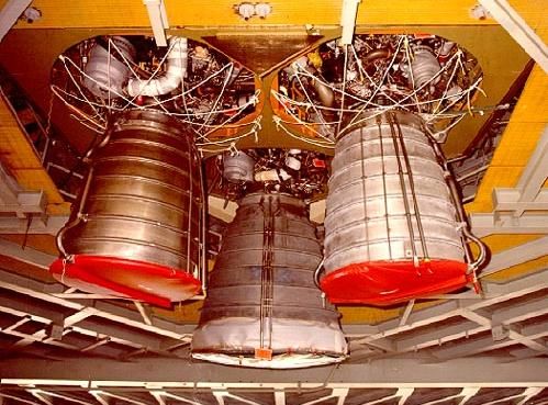
H. Improvements in Reliability and Maintenance
    The design improvements made
throughout       SSME’s        history                                           Ascent Reliability Improved by
significantly improved reliability,                                                  Factor of 4 Since STS-6

                                       Catastrophic Failure Probability
reusability, and maintenance. The

                                          3-Engine Cluster Ascent
block changes discussed above and
the implementation of AHMS
culminated in a four-fold reduction in
the probability of a catastrophic
failure due to a SSME (Figure 10).
Useable life on all components also
increased significantly. Many major
components were tested in excess of
100 times.

    With the increases in reliability
and durability of components,                                     |         |           |          |        |
                                                         Phase II   Block I   Block IIA   Block II   AHMS
maintenance       has    also   been
significantly reduced.      A major                                      SSME Configuration
portion of the maintenance reduction
                                          Figure 10. SSME Reliability Improvements
came with the incorporation of the
Block I and Block II high pressure
turbopumps. The turbopumps do not have to be removed after flight for inspections, eliminating a significant
amount of engine disassembly and reassembly effort. The time required to inspect and prepare an engine between
flights has been reduced by 57% as illustrated in Figure 11.

                                   Orbiter Processing Facility
             SSME R/R        Pad            Vehicle Assembly Building

            Phase II                 Engine                                          •   Engines removed from vehicle post-flight
                                                                                     •   Several major components removed after
                                                                                         every flight

            Block I                                                                  •   On-engine inspection of Block I HPOTP

                                                                                     •   57% less maintenance than Phase II
                                                                                     •   On-engine inspection of Block II HPFTP
            Block II                                                                 •   Check valve filters added
                                                                                     •   Inspections reviewed/optimized

Figure 11. Maintenance Improvements Throughout SSME History

                                                                          III.

                                                      9
                              American Institute of Aeronautics and Astronautics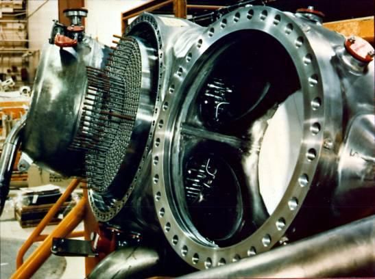
IV. Engine Assembly and Processing

A. Engine Assembly
    For the majority of the Space Shuttle Program, SSMEs were assembled at Pratt & Whitney Rocketdyne’s
Canoga Park, California facility. Engines were then shipped to Stennis Space Center (SSC) for testing.
Development engines remained at SSC. Flight engines were tested and, pending successful post-test inspections and
a completed engine acceptance review, delivered to Kennedy Space Center where they were readied for flight. KSC
personnel maintained and inspected the engines pre- and post-flight. Processing activities evolved with the program.
Though originally built in Canoga Park, the set of Block I engines was recycled into either Block IIA or Block II
engines at KSC. In addition, new engines built after these recycles were all assembled at KSC. All the engines
either recycled or built at KSC were shipped to SSC for testing.

B. Engine Post-Flight Processing
    Because the SSME was a reusable engine, inspections and maintenance were required between flights. The
standard processing flow for any mission began at the end of the previous mission (Figure 12). After each landing,
the Orbiter was returned to the Orbiter Processing Facility (OPF). Landings at sites other than KSC were supported
by KSC personnel in order to ensure that all standard processing necessary prior to ferry flight occurred as it would
have at KSC. Early in the Shuttle Program, engine maintenance was accomplished while the engines were still
installed in the Orbiter’s aft compartment unless an anomaly required their removal. Orbiter processing with
SSMEs installed generated work conflicts in the aft compartment. Beginning with STS-26R in late 1988, SSMEs
were removed after each flight. This resulted in an overall reduction in Orbiter processing flow duration. After
removal, engines were moved to the SSME Processing Facility (SSMEPF) for inspections and maintenance.
    Returning engines were subjected to a rigorous series of inspections documented in the Operation, Maintenance,
and Requirements Specification Document. A set of standard repairs existed for many conditions. Anomalies that
were found to be outside the documented set of acceptable or repairable limits were evaluated by the SSME
engineering team before repair or re-use. Performance data was scrutinized by NASA and Pratt & Whitney
Rocketdyne for any anomaly that might require additional inspections or analysis. Logistics data was also
scrutinized. Starts and seconds for all serialized parts were maintained in an electronic database along with
applicable inspection and life limits. Following every mission, the database was checked and, if the remaining life
on hardware was less than required for the subsequent mission, the applicable components were replaced.

                                                        10
                                American Institute of Aeronautics and Astronautics
Figure 12. Typical SSME Processing Flow at Kennedy Space Center
After all required post-flight work was accomplished, the engines were moved to the OPF and installed for the
next flight. Installation typically took one shift per engine. The Orbiter was eventually rolled out of the OPF and
into the Vehicle Assembly Building (VAB) and stacked. Once the vehicle was secured at the Pad, Flight Readiness
Tests (FRTs) were conducted on the engine to check the control system. Additional leak checks and visual
inspections were performed close to launch to ensure that no collateral damage occurred to the engines during final
Orbiter or vehicle work.
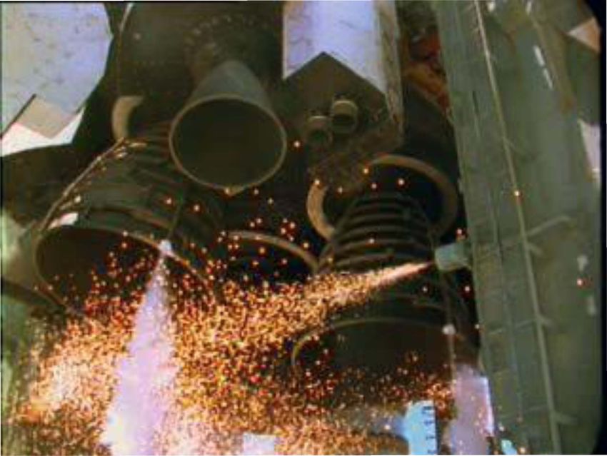
V. Testing4
Testing throughout the SSME program was used to develop and
prove the design, understand operation, reveal failure modes, and
investigate and resolve anomalies. Component level tests and rig
tests of subcomponents were crucial to SSME’s success and were
used in many ways including developing and investigating the
design of seals, investigating issues such as anomalous frequencies
on impellers, demonstrating durability of bearings, and developing
components like turbopumps. These smaller scale rig and
component tests yielded faster and cheaper results over wider
operational ranges than would have been possible with engine-level
testing alone. However, it is the engine-level tests that were
ultimately used as a measure of flight readiness for the engine and its
Figure 13. SSME Test at SSC components.
Throughout the SSME program, engine-level tests were
conducted primarily on four test stands at Stennis Space Center (SSC) in Mississippi, though engine testing has also
been done at the Rocketdyne Santa Susana Field Laboratory in California and on the Technology Test Bed (TTB) at
Marshall Space Flight Center (MSFC) in Huntsville, Alabama. Engine testing began in May, 1975 at SSC and
ended there in July, 2009. Engine starts and accumulated time are listed in Table 2.
11
American Institute of Aeronautics and AstronauticsTable 2. SSME Operation—Starts and Seconds
U Location of Engine Hot-fires U Number of Hot-fires U Time in Operation
A1 Test Stand at SSC 1,007 tests 344,458 seconds
A2 Test Stand at SSC 920 tests 301,495 seconds
B1 Test Stand at SSC 363 tests 165,279 seconds
Main Propulsion Test Article (MPTA) 18 tests of a 3-engine cluster
10,804 seconds
at SSC = 54 hot-fires
A3 Test Stand at Santa Susana 320 tests 57,742 seconds
Technology Test Bed (TTB)
66 tests 7,939 seconds
at MSFC
Flight Readiness Firings 7 FRFs of a 3-engine cluster
449 seconds
on Orbiters at KSC = 21 hot-fires
On-Pad Aborts 5 aborts of a 3-engine cluster
45 seconds
at KSC = 15 hot-fires
135 launches of a 3-engine cluster
Space Shuttle Launches 207,466 seconds
= 405 hot-fires
TOTAL 3,171 hot-fires 1,095,677 seconds
SSME test objectives can be divided into development, certification, and operational tests. Some tests had
objectives in multiple categories, for example sometimes certification tests of improved components occurred during
operational testing of an engine configuration.
A. Development Testing
Development tests were conducted on the basic design and were used to develop safe start and shutdown
transients, demonstrate mainstage operation, and evaluate the integrity of the hardware. This phase helped form the
foundation of the program, demanded navigation of a very steep learning curve, and yielded results that shaped the
final engine design.
The first tests were designed to develop Mixture Ratio Control:
Thrust Control:
Open-Loop
Open-Loop
Open-Loop
Partial Closed-Loop
Open-Loop
Full Closed-Loop
Full Closed-Loop
Full Closed-Loop
the start sequence (Figure 14). Math 110
models indicated propellant conditions and 100
valve timing would be critical. It took 37 90 CCV Command
MFV
Valve Commands (% Full Open)
tests and 13 turbopump replacements to 80
Command
achieve minimum power level, which was 70 FPOV Command
50% RPL at the time, and ninety-five tests 60
OPOV Command
to reach 100% RPL. It was late in 1978 50
before the first flight start sequence was 40
finalized.1,2 During the first development 30 MOV
Command
tests, much was also learned regarding the 37 tests and 13 turbopump
20 replacements required before
processing and preparation of the engine. 10 achieving mainstage power level
Pre-start thermal conditioning, purging 0
requirements, and engine controller 0.0 0.5 1.0 1.5 2.0 2.5 3.0 3.5 4.0 4.5 5.0
Time From Engine Start (secs)
software for monitoring and control were
established. Post-test processing such as
Figure 14. SSME Start Sequence
engine drying, inspection techniques, and
leak checks were developed, which formed
the foundation for future flight processing requirements.
Testing of the FMOF engine configuration continued to aggressively explore the capability of the engine and its
major components. Figure 15 illustrates the problems encountered during the FMOF development history. Each
problem led to insight into engine operation as well as durability, and each problem resulted in redesigns to resolve
12
American Institute of Aeronautics and Astronauticsthe issues. Engine development tests conducted during this period included tests demonstrating malfunction modes
such as loss of electronic redundancies and loss of hydraulic pressure.
80 16
Also in this early part of the
The Problems
70 1. Start Sequence 14 program, a series of tests was
2. High Pressure Fuel Turbopump Whirl 4 conducted at SSC to simulate
Test Seconds (Thousands)
3. High Pressure Oxidizer Turbopump Explosion
60 4. Fuel Preburner Burn Through 12 the orbiter’s aft section
7
Number of Tests
3
5. High Pressure Fuel Turbopump Turbine Failure
50 7
6. Main Oxidizer Valve Fire 10
including a cluster of three
7. Nozzle Steerhorn Failure 6 SSMEs. The hardware
8. Main Fuel Valve Housing Rupture
8
40 8 accumulated to conduct these
3
Test Seconds tests was dubbed the Main
30 5 6
3 Propulsion Test Article
20 3 STS-1 4 (MPTA). Eighteen tests were
5
5
4
Rated Power Level
conducted on the MPTA.
10 2 2
1
Test Seconds The testing that immediately
0 0 followed the first Shuttle flight
1975 1976 1977 1978 1979 1980 1981 began to push the boundaries of
Year engine operation. Tests were
conducted for longer run times
Figure 15. Development History—Tests and Problems Prior to STS-1
and at higher power levels
leading to the certification of
the Full Power Level engine and beyond. Development testing was conducted on all proposed significant upgrades
incorporated into SSME throughout the Shuttle program.5
B. Certification Testing
Certification of an engine configuration involved testing multiple engine samples using aggressive test profiles
that explored the boundaries of the engine-to-vehicle interface requirements. In order to gain confidence in the
FMOF engine for flight, a Preliminary Flight Certification (PFC) test program was conducted prior to the first flight.
Prior to STS-1, SSME had accumulated 726 starts and over 110,000 seconds.
Just as certification was required before the first flight of an engine configuration, it was also required before the
flight of any design change. In some cases, small changes to hardware were certified by similarity to the previous
design of the part or by analysis. Significant changes often required certification tests.
The number of tests required, test profiles, and test durations included in a certification plan depended on the
complexity or extent of the changes being incorporated into the baseline design. For example, one change to Liquid
Air Insulation required only one certification engine test. The advent of the Block II HPFTP required a certification
series of twenty-two tests on each of two samples.
Typically, certification tests were designed to exercise the boundaries of operation expected in flight so that as
many conditions as possible are experienced for the first time in a ground test rather than in flight. Since design
changes were incorporated periodically throughout SSME’s history, certification tests were almost continually a part
of SSME’s testing program and were essential in proving the flight-worthiness of all SSME hardware.
C. Operational Testing
Operational testing was conducted on hardware designs already approved for flight. Every major component on
every SSME was acceptance tested prior to flight. Additional reasons for conducting tests on production hardware
are below.
1. Issues Affecting Single Components or Engines
There were many issues that only affected specific parts. For example, hardware discrepancies that occurred
during fabrication on individual parts sometimes were discovered during an acceptance test. Often, the replacement
of hardware required another test to ensure the problem was fixed. Additionally, repairs or processing escapes
occurred that required testing before continued flight use. For example, unique post-flight Nozzle tube repairs
sometimes required testing before returning to flight.
2. Issues Affecting All Units of a Given Component
Sometimes problems were discovered that called into questions the integrity of the whole fleet of a component.
If the fleet was life limited to something less than required to meet the flight manifest, all units were rebuilt and re-
acceptance tested. For example, a generic issue with the manufacturing of a filter internal to the Main Engine
Controller forced all units to be life-limited, rebuilt with replacement filters, and re-acceptance tested.
13
American Institute of Aeronautics and Astronautics3. In-Flight Anomaly Resolution, Investigation of a Ground-Observed Issue, and Development of Flight Rationale
Quite often, tests on production designs were required to investigate issues and resolve anomalies that did not
appear during development or certification. Sometimes these anomalies occurred due to the number of cycles on the
hardware being tested and therefore appeared after the development phase. On other occasions, they appeared
during production because they were related to specific stack-ups of tolerances or environments that had not
occurred previously. The SSME was reusable, and statistically significant numbers of them were not built. It was
impossible to test every combination of tolerances, even in one component, prior to flight. Occasionally issues arose
for which analysis alone could not provide flight rationale, whether the issue was discovered on the ground or in
flight, and tests are required. When anomalies occurred during a flight, the ensuing investigation often resulted in a
requirement for ground tests to be conducted.
4. Vehicle Issues
Vehicle issues sometimes impact or implicate SSME and require ground testing for resolution. For example,
when inspection of orbiter MPS flowliners in 2002 found cracks just upstream of the inlet to the Low Pressure Fuel
Turbopump (LPFTP), several subcomponent tests were conducted to investigate the interactions between the engine
and vehicle. In addition, modifications were made to engine test stands so that the problem could be further
investigated. The test results were used to set limits on operational speeds of the LPFTPs so as to refrain from
operating in a high order cavitation regime detrimental to vehicle hardware. It was also discovered during this time
that the same high order cavitation that affected upstream hardware also interfered with predicted blade modes in the
LPFTP, so the operational placards protected both sides of the interface.
5. Flight Rule Changes and Demonstration
Flight Rule demonstration was needed to support potential changes and was sometimes requested because
conditions had never been previously run.
6. Off-Nominal Testing
Off-nominal testing was used throughout SSME’s history as a method of providing more extensive knowledge of
how the engine operates and as a tool for determining margins against undesirable conditions. These tests generally
incurred more risk since the engine was being pushed outside its normal operating envelope. A great deal of
analysis, planning, and coordination was required to ensure the tests were conducted successfully and safely. Off-
nominal tests included those designed to explore structural and performance margins, verify fail-operational (fail-
op)/fail-safe conditions, expand the launch criteria envelope, test the limits of ICD requirements, demonstrate
operation at redline limits, examine the effects of process creep, demonstrate the durability of hardware with known
flaws, and expose issues that could be related to the accumulation of starts and/or seconds of operation.
Malfunctions at every stage of the launch: chill, start, mainstage, and shutdown were purposely introduced in ground
tests. Off-nominal tests included chill bleed interruptions, reduced chill-flow rate, purge interruptions, controller
fail-op/fail-safe demonstrations such as controller major cycle restarts and controller channel switch-over.2
Additionally, tests to simulate an SSME application for upper stage were conducted. In every case the engines
performed safely and as expected.
D. Testing Summary and Conclusions
Testing was an integral part of the SSME project and was critical in the success of the Shuttle Program. Tests
were conducted on this engine for more than thirty years and made it a very well-understood liquid rocket engine in
spite of its complexity. Testing was used to develop the engine, to expand operating envelopes, to investigate and
resolve anomalies, and to implement design changes that added to the durability and operational envelope of the
engine.
Many problems were discovered through extensive testing. Sometimes design changes that seemed small were
found to have adverse impacts large enough to cause major failures. Conversely, sometimes design changes thought
to be large and significant proved to be improvements at their first implementation. Without testing, the effects of
modifications to systems as complex as SSME are impossible to accurately determine.
While the benefits of testing are obvious at the onset of an engine development program, it is sometimes less
obvious how important maintaining an active test program is in the production portion of a program. SSME used
engine testing many times near the close of the program to develop flight rationale. Additionally, several large
problems did not present themselves until late in production which, without an active test program, would have
proved exceedingly difficult if not impossible to overcome.
14
American Institute of Aeronautics and AstronauticsVI. Benefits of a Long Program, Testing, and Reusability
SSME used its strong engine test program to find problems on the ground in order to prevent encountering them
in flight. While several anomalies were noted during ascent, the engines operated safely and successfully on every
flight. In addition to testing, another reason for this was the benefit of flying a reusable engine. Reusability forced
long duration testing on the ground (every design was allowed to fly only 50% as long as it had been tested) and
inspections of returning hardware. Environments can be predicted and, to a degree, measured with instrumentation,
but post-flight inspections offered insight into exactly how each part behaved. Measurable improvements
throughout the history of the program have been observed in the reduction of launch delays as illustrated in Figure
16. The more the SSME team strove to understand its hardware through extensive testing and inspections, the more
they tried to improve it, and the safer it got. The final 63 consecutive launches occurred without an SSME-related
delay.
10
Flights per Calendar Year
9 A Pad Abort
8 D On-Pad Delay
7 S On-Pad Scrub
D
6
S,D
5
A A
4
D S D
3
D
2
S D,A
1
D
0
1988
1989
1990
1991
1992
1993
1994
1995
1996
1997
1998
1999
2000
2001
2002
2003
2004
2005
2006
2007
2008
2009
2010
2011
Figure 16. Launch Delays Due to SSME Throughout the History of the Program
This greater understanding and improved design of the engine also resulted in a decline in major engine ground
test incidents. Figure 17 illustrates the total seconds of the SSME test program and the number of incidents over the
years of operation.
1,200,000 Engine Configuration Changes: Phase II Block I Block IIA Block II
1,100,000
Configuration
1,000,000
Upgrades
900,000 High Power
Cumulative Time
800,000 Level Testing Return to Flight
700,000 Columbia Incident
Early
600,000 Development
500,000
400,000
Return to Flight
300,000
Uncontained
200,000 Major
Challenger Incident
100,000 Significant
First Flight
0
2000
2005
1975
1980
1985
1990
1995
Calendar Years (1975—2008)
Figure 17. Incident Occurrences Throughout SSME’s History
Shuttle flight success was not the only outcome of the amazing history SSME enjoyed. Engineering profited as
well. Many engineering disciplines were required to achieve and maintain SSME’s success. SSME in return was
15
American Institute of Aeronautics and Astronauticsresponsible for the advancement in the state of the art in many engineering disciplines. For example, in fluid
dynamics, extensive work was conducted understanding cavitation and increasing the abilities to model it; in
structural dynamics, knowledge was gained in finite element prediction techniques, data acquisition techniques, and
structural dynamics of extremely high frequency responses; in rotordynamics, better models exist to predict
instability, synchronous responses, and external loading; in materials, continuous improvements were made in
materials characterization and processing for reliability, performance, producibility, and reduced cost.
VII. Conclusion
The Space Shuttle Main Engine is the most technologically-advanced, high-performance rocket engine ever
produced. SSMEs successfully launched 135 Space Shuttle missions and accrued over one million seconds of hot-
fire time during ground tests and flight operation, more than any other large rocket engine, with a demonstrated
engine reliability in excess of 0.9995. The SSME was instrumental in material characterization and has advanced
the state of the art in several engineering disciplines. The extensive ground test program, multiple flights, and the
ability to inspect the hardware after tests and flights made the SSME arguably the most well-understood rocket
engine in history. The experience gained during the evolution of the SSME program forms a fundamental
foundation of liquid propulsion knowledge to benefit all future endeavors.
Acknowledgments
The authors would like to thank Jerry Cook, Steve Wofford, Fred Jue, Philip Benefield, Lewis Maddux, and Ken
Kan for their 2010 JANNAF Liquid Propulsion Conference papers documenting the evolution, operation, and
testing of the SSME. The JANNAF papers listed in the References section were used extensively throughout this
paper.
The authors also gratefully acknowledge the accomplishments of the many people across the country and
internationally who have been involved in designing, manufacturing, developing, testing, analyzing, and producing
the SSME throughout its history, and they are immensely thankful to have had the opportunity to participate in such
a historic achievement. In one paper, it is impossible to fully cover the rich history or the many lessons that have
been learned from SSME.
References
1
Biggs, Robert E. Space Shuttle Main Engine: The First Twenty Years and Beyond. American Astronautical Society History
Series, Volume 29. Univelt for American Astronautical Society, San Diego, CA, 2008.
2
Bradley, Douglas P. and Philip A. Benefield. “Space Shuttle Main Engine Operational Capability.” 57th Joint Army-Navy-
NASA-Air Force Propulsion Meeting / 5th Liquid Propulsion Subcommittee Meeting. Colorado Springs, CO. May 3-7, 2010.
3
Hale, Wayne, Katherine Van Hooser, Greg Swanson, Ph.D, et al. Wings in Orbit: Scientific and Engineering Legacies of
the Space Shuttle. NASA/SP-2010-3409. U. S. Government Printing Office, Washington, D.C., 2010. Page 285.
4
Van Hooser, Katherine P., Lewis J. Maddux, and Ken Kan. “History and Benefits of Engine Level Testing Throughout the
Space Shuttle Main Engine Program.” 57th Joint Army-Navy-NASA-Air Force Propulsion Meeting / 5th Liquid Propulsion
Subcommittee Meeting. Colorado Springs, CO. May 3-7, 2010.
5
Wofford, Steven J., Fred Jue, and Jerry R. Cook. “Space Shuttle Main Engine Design Evolution.” 57th Joint Army-Navy-
NASA-Air Force Propulsion Meeting / 5th Liquid Propulsion Subcommittee Meeting. Colorado Springs, CO. May 3-7, 2010.
16
American Institute of Aeronautics and AstronauticsSpace Shuttle Main Engine —
The Relentless Pursuit of Improvement
Katherine Van Hooser Douglas P. Bradley
SSME Chief Engineer SSME Chief Engineer
NASA Marshall Space Flight Center Pratt & Whitney Rocketdyne
Huntsville, AL Canoga Park, CA
AIAA SPACE 2011 Conference
Long Beach, CA
Pratt & Whitney Rocketdyne
September 27-29, 2011Space Shuttle Main Engine (SSME)
Relentless Pursuit of Improvement
• SSME 101
• Design evolution
• Verification by ground test
• Analytical tool evolution
• Lessons
Pratt & Whitney Rocketdyne
2SSME is the First Reusable Large
Liquid Rocket Engine
Propellants O2/H2
Rated power level (RPL) 469,448 lb
Nominal power level (104.5% RPL) 490,847 lb
Full power level (109% RPL) 512,271 lb
Chamber pressure (109% RPL) 2,994 psia
14 ft Specific impulse at altitude 452 sec
Throttle range (% RPL) 67 to 109
Gimbal range +/- 11°
Weight 7,748 lb
55 flights
Service life
27,000 seconds
3,171 starts
Total program hot-fire time
7.5 ft 1,095,677 seconds
Pratt & Whitney Rocketdyne
3High Performance
Staged Combustion Cycle
Hydrogen Oxygen
Inlet Low-Pressure Inlet Low-Pressure
Fuel Turbopump Oxidizer Turbopump
(LPFTP) (LPOTP)
Main Oxidizer
Oxidizer Valve (MOV)
Valve
(FPOV) Oxidizer Oxidizer
Preburner Valve
Fuel Main (OPOV)
Preburner Injector
Powerhead
Main
Fuel
Valve
(MFV) High-Pressure
Main Combustion Oxidizer Turbopump
Chamber (MCC) (HPOTP)
High-Pressure
Fuel Turbopump Nozzle
(HPFTP) • All propellants consumed – performance,
efficiency
Chamber
Coolant • Five variable valves – flexibility, wide
Valve (CCV) operational control
• Serial low- and high-pressure pumps –
wide flow range
• Fail-op / fail-safe control system
Pratt & Whitney Rocketdyne
4Pratt & Whitney Rocketdyne
5SSME Block Improvements Timeline
2011
1970s 1980s 1990s 2000s 2010s
STS-1 STS-51L STS-107 STS-135
First Manned
Orbital Flight
1st Test 1st Flight
Full Power
Level
1st Flight
Phase II
1st Flight
Block I/IA
1st Block I, IA Flights
1st BII Flight
Block IIA/II
1st BIIA Flight Health Management 1st Flight
Pratt & Whitney Rocketdyne
6Full Power Level (Phase I) SSME
First Flight — April 1983
Low Pressure Oxidizer Low Pressure Fuel
Turbopump Turbopump
• Turbine discharge • Revised blocking area
turning vane mod
Powerhead
• Changes to Hot Gas Manifold fuel bowl
liner, lox posts in Fuel Preburner
• New flow meter straightener
• Lox post shields
HPFTP
• Kel-F seals
• Smooth interstage seals
• Increased turbine blade tip clearances
HPOTP Nozzle
• Housing material changed • 1st Flight STS-6 (April 1983) • Increased tube wall
thickness
• Added steam loop
• 147 Required Changes from Baseline
Engine Incorporated to Enable
Operation at 109% Power Level
Pratt & Whitney Rocketdyne
7Phase II SSME
First Flight — September 1988
Block II Controller
• New type and increased memory
• Improved producibility and maintainability
• High order language for software
Powerhead
• Main Injector oxidizer inlet vane rework
MCC
• EDNi reinforced outlet neck
HPTPs
• Desensitize coolant system
• Bearing and blade improvements
• Rotor stability
Ducts LPOTP
• Low Pressure Fuel Duct helium barrier • Thrust Bearing
• 1st Flight STS-26R lock-nut spacer
• Fully Recertified to 104% RPL Nozzle
• Added insulation
• 0.9994 Demonstrated High Reliability to aft manifold
and drain lines
Pratt & Whitney Rocketdyne
8Block I SSME
First Flight — July 1995
Two-Duct Powerhead
Alternate High Pressure • Improved liner and injector life
Oxidizer Turbopump • Baffleless main injector
• Precision castings • Thick, cut-back turning vanes
• Ceramic bearing balls • Eliminated 74 welds
• Eliminated seal pressure redline • Part count reduced by 52
• Cycle time reduced 40%
Hot Gas Temp Sensors
Single Tube Heat Exchanger • 1st Flight STS-70 • Improved reliability
• Eliminated all 7 criticality 1
interpropellant welds
• FOD tolerant 25% thicker tubes • Improved Safety, Reliability, &
• Low maintenance
Operability
Pratt & Whitney Rocketdyne
9Block IIA SSME
First Flight — January 1998
High Pressure Fuel
Turbopump
• One-piece EDM turbine inlet
• Increased life turbine blades
Large Throat Main Combustion Chamber • Improved rotor balance Purge Check
• Engine pressure & temperatures reduced up to 10% Valves
• Increased channel wall cooling • Added upstream
• Simple cast manifolds, eliminated 52 welds Filters
• Cost & cycle time reduction over 50%
Main Injector
Specific Impulse
Modifications
• Eliminated parasitic Software
hydrogen losses • Self-calibrating
Low Pressure Low Pressure • 0.4 sec Isp recovery actuators
Oxidizer Fuel • Nominal coefficients
Turbopump Turbopump • 1st Flight STS-89 • Improved logic
• Ceramic bearing balls • Kevlar jacket • >2x Reliability Improvement • Increased redundancy
• Robust rotor insulation thermocouples
alignment • Reblocked nozzle • Certified to 104.5% Nominal Thrust
• Increased • Eliminated plug • Improved Safety, Life, & Operability
performance inducer weld
• Reduced Cost
Pratt & Whitney Rocketdyne
10SSME Block II & AHMS
First Flight — June 2001
Block II High Pressure
Fuel Turbopump
• Improved turbine blade fatigue
capability
• Robust turbine housing
• Pump Inlet Housing burst margin
increased
• Stiffer/heavier rotor
• Robust hybrid bearing systems
• Extensive use of precision investment
castings Advanced Health Management
• Coolant liner redline eliminated System
• Real-time spectral analysis performed
to detect and measure high pressure
• 1st Flight STS-104 turbopump synchronous frequencies
• Controller modified to respond to
• AHMS 1st Flight STS-117 (June 2007) vibration data by disqualifying a sensor
• Improved System Reliability, or shutting an engine down when
necessary
Operability, & Safety
• Goal of 10 Missions Between
Overhauls
Pratt & Whitney Rocketdyne
11You can also read