Small Innovative Launcher for Europe: achievement of the H2020 project SMILE - SMall Innovative ...
←
→
Page content transcription
If your browser does not render page correctly, please read the page content below
7TH EUROPEAN CONFERENCE FOR AERONAUTICS AND SPACE SCIENCES (EUCASS)
Small Innovative Launcher for Europe:
achievement of the H2020 project SMILE
Bertil Oving*, Arnaud Van Kleef*, Bastien Haemmerli**, Adrien Boiron**, Markus Kuhn***, Ilja Müller***, Ivaylo
Petkov***, Ana-Maria Neculaescu****, Tudorel Petronel Afilipoae****
*Netherlands Aerospace Centre - NLR
Anthony Fokkerweg 2, 1059 Amsterdam, Netherlands
**Nammo Raufoss AS
P.O. Box 162, NO-2831 Raufoss, Norway
*** German Aerospace Center - DLR
Pfaffenwaldring 38-40, 70569 Stuttgart, Germany
**** National Institute for Aerospace Research Elie Carafoli - INCAS
Bulevardul Iuliu Maniu no. 220, sect 6, 061126, Bucharest, Romania
Abstract
Today’s market for small satellites is expanding, but there is little capacity for affordable launches. Launch costs of
around €50,000 per kg are required to compete with ride-shares. Hence, production and operation costs are
considered essential. Fourteen European companies and institutes have joined forces in a Horizon2020 project called
“SMall Innovative Launcher for Europe” (SMILE). The project aims at designing a launcher for satellites of about 50
kg and a European launch facility in northern Norway. Critical technologies on propulsion, avionics, and
manufacturing of cost-effective solutions are developed in order to increase the readiness level of a future European
launcher.
1. Introduction
The space market sees nowadays an evolution towards nano- and micro-satellites, that are more and more performant
for all kind of purposes. This trend appears to expand into small satellites constellations, a market which many start-
up companies are already investing in, e.g. Skybox, BlackSky Global and Planet Labs. They are claiming their spot
on the stage next to the big players by having a much faster response to market needs as well as by providing
affordable satellites for: high-definition imaging, climate data acquisition, maritime shipping assets tracking or In
Orbit Demonstration and Validation (IOD/IOV). Their business concept seems to completely out-compete the big
players and they are attracting venture capital as well as the attention of big multinational enterprises not normally
active in the space business.
All these new satellites need an affordable way to get into space, and since their key features are responsiveness,
low-cost and flexibility, the same has to be applied to their launch service. So far, most of these new satellite
companies have to rely on the big players to get their access to space through hitchhiking as secondary payloads on
large institutional launchers. One niche has already been taken by deploying them from the International Space
Station (NanoRacks and JAXA), but these apparently cheap solutions are still based on an extremely expensive
platform. The release from a relatively fixed platform is not as flexible as desired either, as it only provides the
nanosat with an orbit limited to the inclination of the Space Station.
The need for a dedicated launch service for these ever more powerful nanosats, is quite clear to everybody in the
space community. The challenge lies in their limited launch mass, which represents the low-end of the satellite mass
range for which no institutional launchers have been developed. In response to this need, several commercial space
companies have already claimed that they will soon be ready to offer to the market their own version of such a new
launch service, i.e. Virgin Galactic's LauncherOne, Rocket Lab’s Electron, to name but the most matured ones, with
dozen others at different level of development. A 2010 initiative from NASA offering a multimillion-dollar prize
competition to support the development of a dedicated nanosatellite launch vehicle as part of its Centennial
Challenges program was cancelled in December 2012 based on the argument that none of the commercial
Copyright 2017 by The SMILE Consortium. Published by the EUCASS association with permission.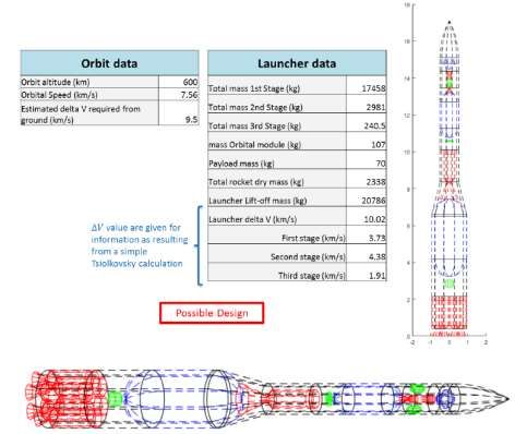
The SMILE Consortium

competitors had the expertise or the means to fulfil the task of developing a complete new nano-launcher. This
should be a reminder that the challenge of developing a dedicated nano-launcher should not be taken lightly!

1.1.   Market Analysis
To properly gauge the demand for small-lift launch vehicles, a detailed assessment of the launch demand
components (by mass vs orbit altitude, by inclination, by country, by sector, etc.) was performed using a database of
launched satellites from Andøya Space Center (ASC). Current and future competitors were also identified to have an
indication for how accessible the specific target market will be by the time SMILE project reaches fruition.

According to numerous market studies, such as the one by SpaceWorks Enterprises below, the number of small
satellites under 50 kg being developed will continue to increase in each year to come, such that from now until 2022,
there will be as many as 3000 nano- and micro-satellites requiring a launch.

                      Figure 1: Nano/microsatellite market forecast by SpaceWorks Enterprises

Despite such impressive figures for the total available market for small sat launches, the demand specific to SMILE’s
accessible target market needed to be assessed.

A full assessment of the demand for launch broken down by mass vs orbit altitude and inclination was therefore
performed using ASC’s proprietary database of previously-launched satellites. The historical data were used to
extrapolate trends and percentages that were then applied against forecasts for total launch demand for small
satellites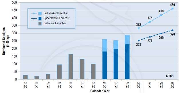
ACHIEVEMENT OF THE H2020 PROJECT SMILE
The desired service of satellite companies can only be met by dedicated small-lift class launchers, which do not yet
exist on the market. This brand new market segment is nevertheless anticipated to open up in the very near future
since, as of September 2016, 38 small-lift launch vehicles around the world were identified to be at different stages
of development, from concept design to flight qualifications. Nine of these are identified as European. This high
number of small-lift launch vehicles under development is unprecedented and demonstrates how much growth is
anticipated in the small satellite market from one side and, from the other side, the extent of the current launch
capabilities gap recognised by the launch services market.
It must be noted that despite the identified high number of launchers under development in the same segment as
SMILE, historically, the percentage of launchers successfully reaching the market is statistically very low. It is
therefore important to distinguish between actual future direct competitors of SMILE already on or about to enter the
market and only future potential competitors, since the credibility of each member in the latter group will need to be
individually evaluated.
Since the goal for SMILE is to develop a European small-lift launcher, it was equally important to assess the
availability of other launch sites from which small lift launchers could launch small satellites into near polar orbit. A
review of launch sites around the world yielded the following findings:
Currently there are no other commercial launch sites existing in Europe that can already offer dedicated launch
opportunities to near polar or polar orbit. There are currently 11 launch sites in the world with SSO and Polar
Orbits injection capability for secondary payloads;
The only European launch site with (near) Polar orbit capability offering launch opportunities for secondary
payloads is Centre Spatial Guyanais, located in Kourou, South America, far from continental European;
There are 2-3 other potential competing launch sites in Europe for vertically-launched vehicles that are currently
being assessed or under development, including Esrange (Sweden) and a new site to be proposed in Scotland.
Esrange, located in Sweden, is similarly home to a sounding rocket launch facility and is also planning to
expand into a small satellite launch facility.
1.2. Small Innovative Launcher for Europe (SMILE)
Fourteen European companies and institutes are joining forces in a Horizon2020 programme called “SMall
Innovative Launcher for Europe” (SMILE). The project aims at designing a small launcher for satellites up to at least
50 kg, demonstrating critical technologies on propulsion, avionics, and production for cost-effective solutions, and
designing a European-based launch facility at Andøya. The technology in the SMILE context involves:
Reusable liquid rocket engines;
Low cost hybrid rocket engines;
Low cost automated manufacturing of composites and advanced materials;
Low cost avionics equipment;
Efficient, easy-to-use payload deployment system;
Low cost ground segment.
The SMILE project is currently preparing for its Mid Term Review.
Figure 2: SMILE consortium (left) & current status (right)
3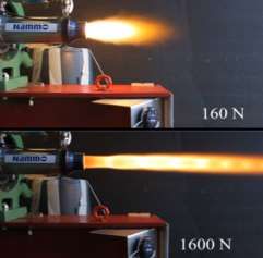
The SMILE Consortium
2. Launcher Design
2.1. System Requirements
Within the SMILE project, a Concurrent Design Team led by NLR is responsible for the launcher design. Instead of
a waterfall process, where strict requirements can lead to costly design solutions, the SMILE launcher requirements
are defined in a flexible way (using the keyword ‘about’), keeping the main goal of being low cost in mind. The main
cost drivers are:
The production of the launcher (size, complexity, tools, materials);
The handling, storage, and transport of the launcher (size, sensitivity, materials);
The organisational structure of the launch provider (facility, logistics, launch preparation, number of
employees).
This means that the design of the launcher should be driven by low-cost production methods, restrictions on logistics,
minimising the personnel involved, and reduction of the overhead whilst upholding a high level of quality and safety.
The launcher is broken down into three major subsystems Engines, Structures, and Avionics, each of which
comprises a number of subsystems of its own. The launcher requirements are defined on both system level and
subsystem level.
To create a process that focuses on cost reduction, the concurrent design process involves not just the obvious multi-
disciplinary domains such as propulsion, aerodynamics, and trajectory analysis, but also the manufacturing and
logistics on a detailed level, resulting in a concurrent top-down and bottom-up approach.
2.2. Multidisciplinary Design Approach
The design of a launcher is a multidisciplinary challenge that requires much iteration, especially at the beginning of
the design phase, when there is still a high level of uncertainty in i.e. the mass breakdown and geometry of launcher
components. Therefore, a best engineering guess is required based on literature supported by modelling and
simulation efforts.
Critical components (i.e. hybrid propulsion components) are already available at higher TRL compared to others
which are expected to be developed throughout the project for which it’s mass and geometry properties come along
with increasing detail. Furthermore, design relations exist among various components. For example, increasing burn
time of engines come along with increasing propellant tanks which need to provide structural stiffness to be able to
withstand the launch loads.
An MDO tool in MATLAB has been developed by NLR to perform trade-offs of launcher configurations (i.e. two
vs. three stage) with various propulsion systems (i.e. hybrid and/or liquid engines). The level of fidelity of the MDO
tool increases with every design iteration, as more design details become known of launcher components in terms of
a mass breakdown and geometry. This increases the level of certainty of both the launcher performance and
geometry.
The MDO approach consists of an iterative process between launcher stage sizing and flight trajectory (not
optimized) simulation to converge to a launcher design solution that reaches the target orbit. In order to compare and
trade-off different launcher configurations in terms of i.e. costs and total weight, these need to be assessed at similar
target conditions. For a target orbit these are expressed in velocity and altitude conditions, so both need to be
controlled to their target end states.
A total of nine stage configurations were considered based on a selection of liquid or hybrid propulsion per stage.
4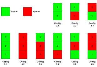
ACHIEVEMENT OF THE H2020 PROJECT SMILE
Figure 3: High-level design approach (left) and the nine launcher configurations (right)
The total mass of the various launcher configurations vary between 16 tons (configuration 3.1: three-stage liquid)
and 26 tons (configuration 2.3: two-stage: 1. liquid, 2. hybrid). Launcher configurations with upper stages based on
hybrid propulsion typically are heavier than liquid propulsion based upper stages, due to the higher dry mass of the
hybrid components. Furthermore, as the burn time of a hybrid engine is limited, the thrust level provided by hybrid
engines needs to be higher as compared to liquid engines in order to be able to lift the upper stage to orbit apogee.
Note that an increase of thrust level by hybrid engines has a positive effect on the launchers performance in terms of
ΔV (less cumulative time for gravity losses) only at the cost of a slight increase in dry engine mass.
A first assessment of the results is done to reduce the number of configurations, which will be further analysed in the
next design cycle. The following considerations are taken into account when selecting the configurations:
The liquid engine has a low TRL, so that it will take time to apply it in an operational launch vehicle, which
increases the time-to-market;
In case of a hybrid engine, the launcher can be made operational sooner, but only if it is all-hybrid. An option is
to start the launch service with an all-hybrid vehicle;
A liquid engine is more expensive due to the propellants and the high combustion chamber pressure. The
cryogenic LOX requires special attention, from the storage, the filling of the tanks, the pumps & piping, and the
igniter. The pump has to be quite powerful (and thus heavy) to handle the pressures;
Even with the additional cost due to mass and complexity, recovery of the first stage has high potential for cost
reduction, especially when the first stage is expensive. Most impact is thus seen for a first stage with reusable
liquid engines;
A unitary concept is based on a single engine design and reduces manufacturing cost. Most effect is gained when
each stage uses the same type of engine;
A hybrid engine typically has a short burn time and thus a high thrust level is needed to obtain enough ΔV. This
leads to relatively high accelerations during launch, which poses constraints to the payload. A limit to the
maximum acceleration is needed leading to lower thrust levels by throttling the engine (but it should be noted
that there is a limit to the level of throttling);
When assessing the configurations, the performance results (geometry and mass breakdown) are combined with
the cost impact analysis.
2.3. Trajectory Optimization
In the context of the SMILE project, INCAS has developed a preliminary trajectory optimization tool which employs
a genetic algorithm in order to search in a global manner a solution for an optimal control problem. The basic
definition of the optimal control problem is the following:
Find the optimal control functions which minimize a performance index f while satisfying a given set of equality
and inequality constraints.
5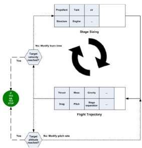
The SMILE Consortium

Starting from this definition, a structure of the optimization tool had been a priori elaborated which later on became
the basis of the implementation process. This structure is presented in the picture below.

                            Figure 4: Logical diagram of the trajectory optimization tool

The genetic algorithm initiates an inner iteration loop that evaluates at every iteration the objective function f (the
fitness function) attempting to minimize it. Within the objective function, the trajectory is simulated using a 3DoF
dynamic model. The output variables of interest from the trajectory simulation are the ones corresponding to the orbit
and path constraints defined in the input file. Using these, an individual evaluation is performed with respect to the
constraints, after which all performance indices together with the payload are combined in the objective function.

The next step the genetic algorithm takes is to generate a new set of decision variables (optimization variables)
within the bounds defined in the input file, based on the history of the performance indices encountered during all the
previous iterations. By doing this, the genetic algorithm attempts to find better performance index and proceeds to
the next iteration. The optimization tool is used to assess the maximum possible payload mass for any launcher
configuration.

2.4. Propulsion System
2.4.1. Hybrid Engine
The hybrid propulsion system is based on a modular concept consisting of hybrid rocket motors clustered together.
Modularity is obtained at different levels: at component level, at the propulsion level and at the level of the stages.
For the intended market, cost is essential. Reusability of components will lead to cost reductions through volume
production and increased reliability through automated production. The reuse of the propulsion is primarily based on
a high thrust motor. For an upper stage, a high performance engine with a more moderate thrust requirement and
longer burn-time is needed to obtain orbit insertion. All Nammo's hybrid rocket motors are in principle throttleable
and capable of repeated stop and restart; throttleability is a hard requirement for the third stage engine in order to
enable accurate orbit insertion.

Nammo’s hybrid technology has been matured since 2003 through several research and technology programs, either
nationally or in collaboration with international partners ([11]). The motors developed at Nammo combine the
environmental friendliness and cost effectiveness of a H2O2-HTPB hybrid rocket motor, with a high regression rate
and an excellent overall combustion efficiency (up to 98%). With these efficiencies proven and repeatedly confirmed
[12], Nammo has opened the door for a new look at implementing hybrid rockets into real applications.

6
ACHIEVEMENT OF THE H2020 PROJECT SMILE
Figure 5: One of the First Firings of the Hydrogen Peroxide Based Hybrid Rocket (left) and Demonstration of the
Extreme Throttleability of the Hybrid Rocket Motors from Nammo
Nammo’s motors are all based on a novel concept of hybrid rocket engine technology. They use high concentration
hydrogen peroxide (87.5% H2O2) as oxidizer and hydroxyl-terminated polybutadiene (HTPB) rubber as fuel. Figure
6 shows the working principle of Nammo’s hybrid motor. The incoming liquid oxidizer is decomposed through a
catalyst bed into hot steam and gaseous oxygen at a temperature of 670°C.
It then continues through the injector and enters the combustion chamber in hot gaseous form, where ignition of the
hybrid combustion occurs instantly without any dedicated ignition device due to the high temperature which is
sufficient to vaporize the solid fuel. Vortex injection helps in maintaining a high heat flux into the fuel surface and in
achieving appropriate mixing of the reactants. Ultimately, this allows sustaining high combustion efficiency. The hot
combustion gases are then expelled through a standard bell nozzle, generating the thrust.
Figure 6: Schematic Showing the Working Principle of the Unitary Motor
Compared with solid rocket motors, the hybrid motor designed by Nammo has a rich set of attractive features:
Self-ignition increasing engine start reliability and enabling an unlimited restart capability;
Wide range throttling with limited performance losses;
Green life cycle and exhaust properties;
Solid inert fuel and high-density green storable oxidizer;
High engine combustion efficiency, performance and stability;
Simplicity of a single circular port and single feedline configuration;
Low development and operational costs.
Most of these properties are shared with the inherent properties of other hybrid propulsion technologies, but some of
them are unique for the H2O2 based technology perfected by Nammo. Some of these features are as well common
with liquid rocket engines, but compared with liquid engines, the architecture of the hybrid is much simpler and the
same features are obtained for a fraction of the cost.
7The SMILE Consortium
The aforementioned features are implemented in Nammo’s currently developed hybrid motor, a 30 kN-class engine
named the Unitary Motor 1 (UM1). Through two tests campaigns performed between 2015 and 2017, the burn time
has been progressively ramped-up and the dry mass of the motor lowered. The UM1 demonstrated great behaviour
both in terms of performance and stability since the very first test firing, and continued to do so throughout the rest of
the test campaigns. More details about the UM1 and the results of the performed test campaigns can be found in the
dedicated paper [13].
Figure 7: First firing of UM1 on May 19th 2016
While being primarily developed for sounding rocket applications, the technology matured through the Unitary
Motor 1 and the clustering concept can be directly implemented for a nano-launcher, for which the cost effectiveness
of the propulsion system is just as important as shear performances. Compared to the Unitary Motor currently being
developed, the motors used for a launcher will have to be adapted for the peculiarity of the mission and of the launch
vehicle. In terms of reusability, having propulsion elements used for both nano-launcher and sounding rocket would
as well help in reducing the costs.
Firstly, a trade-off at system level has to be made between thrust, burn-time and motor envelope for a given total
impulse provided by the motor. Indeed, the higher the burn time, the bigger the diameter of the motor, which in turns
implies a bigger diameter of the stage. On the other side, a too high thrust could mean as well too high acceleration
for the payload.
Secondly, where the optimisation of the dry mass is not so critical for a sounding rocket, it becomes quite the
opposite in a launcher. Nammo is therefore investigating, along with the other partners in the SMILE project, means
to lower to a maximum the dry mass of its hybrid motor and of the full propulsion systems. Notably, investigation is
carried out on reducing the mass of the catalyst assembly and of the motor case, using new technologies (3D
printing, composite materials) as well as the know-how acquired with the latest engine tests.
Finally, the oxidizer feeding system must as well be adapted to the size and requirement of a nano-launcher. Up to a
certain level of oxidizer mass-flow, a pressure fed-system can be considered. With the hybrid motors operating at a
somewhat low pressure (20-40 bars), the required pressurization system can remain quite small. This could then be
the case of an upper stage for example. On the contrary, a booster stage will most likely have to be fed with a turbo-
pump due to the high mass-flow and overall size of the otherwise pressurized oxidizer tank. For the turbo-pump,
Nammo is working within SMILE with WEPA technology in order to find the optimal architecture.
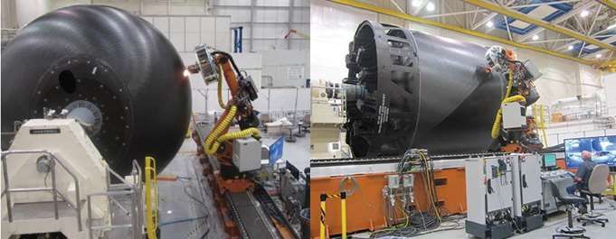
As an example of the work done in SMILE, Figure 8 shows a possible architecture of a three stage hybrid rocket
answering to the requirement of the typical SMILE mission scenario (i.e. 50 kg payload on a SSO 600 km orbit).
This architecture is the result of a common work between the different partners, as well as the development within
the project of dedicated design tools. With respect to the hybrid propulsion, the numerical tool is based on the know-
how of Nammo to propose scaling laws of the motors for the various thrust level and burn-time needed by the
mission. It includes as well results of the work achieved by the partners on the different parts (e.g. turbo-pump
design, oxidizer tank structure).
The first stage propulsion is composed of six 100 kN class Unitary Motor 2 fed by a single turbo-pump. The second
stage is then composed of a single motor of the exact same design, but for a slightly higher thrust due to the extended
nozzle adapted for higher altitude burn. The third stage is then composed of a single 10 kN class motor in a pressure
fed configuration for orbit insertion.
8ACHIEVEMENT OF THE H2020 PROJECT SMILE
In order to minimize the development cost, the same motor is used for both first and second stage. Only the nozzle
exit cone will have to be adapted for the two different environments (low and dense atmosphere for the 1 st stage, high
atmosphere and low vacuum condition for the 2 nd). This considerably simplifies as well the industrial set-up needed
to achieve the foreseen flight rate.
Both stages are fed by a single pump instead of having a common pump design for the two stages. The main reason
is to reduce the complexity of the stage and thus reduce the risk of failure. Also, the recurring cost of a turbo-pump is
seen as considerably higher than the recurring cost of a hybrid engine. It is then as well better to reduce the number
of those expensive parts.
The development of two turbo-pumps is of course more costly than a single one, but commonalities between the two
system (same pressure rise and fluids, just two different mass flows) would most likely help keeping the cost as low
as possible. The coupling between the hybrid motors and the turbo-pump system is a major task within the
propulsion work of the project.
The third stage uses a pressure-fed configuration as the mass flow (about 4 kg/s of H 2O2) is easily manageable with
such a system. There is a slight mass penalty (seen by the reduction in the delta V produced by this stage) but this
would definitely help keeping the cost low.
Figure 8: Possible architecture for a three-stage hybrid launcher (configuration 3.2)
Based on the input provided at launch system level, different architecture can be defined. A trade-off is always
needed between the need for performance and the need to have a cost effective solution. The final configuration
might therefore not be the one with the lower total mass, nor the one with the highest performance, as a heavier but
cheaper system might do the work just fine.
As next step within the SMILE project, Nammo will see to refine with its partner the architecture of the launcher,
while working on the optimization of its system. The dry mass of the motor is seen as the primary point to look at
and preliminary estimation reveal that substantiate gain can be obtained. In parallel, Nammo is also working with
partners in order to design prototype parts that could potentially bring closer the realisation of those motors.
9The SMILE Consortium
2.4.2. Liquid Engine
In general, liquid propulsion is a reliable technology that is quite flexible as the engines can be throttled to a wide
range (5-100%) and are easily re-ignited. For the current configuration, the propellant combination LOX/kerosene Jet
A-1 is considered as the most appropriate. Jet A-1 is a worldwide available, cheap fuel that can be easily stored and
refueled. The considered configuration is a liquid-propelled three-stage launcher. The planned staging mass fraction
is 30:6:1.2. The liftoff mass is set to 16 ton with an initial thrust/weight ratio of 1.4. The considered feeding systems
consist of a turbo-pump-fed system for the first stage and pressure-fed systems for the upper stages [3], as seen in
Figure 9.
Figure 9: Generic three-stage liquid launcher (configuration 3.1) with kerosene/LOX
Usually, the propulsion system is the most expensive part of the launcher. Thus, it would beneficial to retrieve the
engines back after each mission. In contrast to solid, hybrid or classical liquid engine approaches, liquid engines
based on a ceramic design are very promising candidates with respect to reusability aspects as they offer [4][5][6]:
Improved lifetime;
Thermo-shock resistance;
Thermal-cycling ability;
Reliability and damage tolerance;
Reduction in structural weight;
Increased oxidation resistance;
Potential fail-safe operation;
High specific strength at elevated temperatures;
Low thermal expansion.
Hence, this specific kind of propulsion system using ceramics is well suited and applicable as it can be thermally
cycled without degradation, which is not the case for metallic approaches. Especially in combination with the
transpiration cooling technique and the use of fiber reinforced structures, the engine’s structural weight can be
significantly reduced.
Furthermore, ceramic matrix composite (CMC) materials are high-temperature resistant and can be used in hot gas
environments without cooling of the engine components like injector face plate, combustion chamber, throat, and
nozzle. The envisaged CMC is C/C-SiC, developed and manufactured by the Institute of Structures and Design of
DLR (Stuttgart, Germany); this material is considered favorable for oxidation strength, damage tolerance, low
thermal expansion coefficient and low density for space components [7][8]. Classical passive, convectively fuel-
cooled component designs were investigated in the past. Additional coating systems for enhanced oxidation
resistance and increased maturity levels as well as transpiration cooling technique can be also applied.
The costs of highly curved structures out of C/C-SiC are high due to demanding manufacturing efforts. Hence, the
use of flat or 1-D bended plates was shown to be favorable [7] as economic considerations for small sat launchers are
very important. Taking this into consideration, a possible solution for the first stage could be a nozzle with a linear
aerospike in a hexagonal arrangement.
This way, the first stage can be equipped with 30 unitary combustion chambers and still provide a cost effective and
simple design (as shown in Figure 10). The second stage will have 6 combustion chambers with C/C-SiC bell-shaped
nozzles (see Figure 9).
10ACHIEVEMENT OF THE H2020 PROJECT SMILE
For hydrocarbon propellants, the general feasibility was successfully demonstrated in gaseous oxygen and kerosene
combustion environment within the EC project ATLLAS [6][9]. Various CMC materials were tested, whereas oxide
CMCs were also found suitable for this kind of application as the material is able to withstand hot gas oxygen
attacks. With respect to cooling performance, Jet A-1 as hydrocarbon-based coolant turned out to be sufficient
[6][10].
Figure 10: First stage aerospike configuration TCA-A for launcher concept 3.1 (SLR1)
This kind of chamber arrangement has the following advantages:
Clustering enables the usage of the same engine components for all of the three stages, e.g. injector, combustion
chamber, and valves. Such components are suited for 3D printing, for which 3D Systems is the partner.
Throttling capability of the chambers of the first and second stages allows for a gimbal free thrust vectoring.
The most appropriate way to arrange the 30 combustors under the resulting geometric constraints is the
implementation of the faceted aerospike nozzle and the clustered engines.
Additional geometric constraint resulting from lower combustion pressures is the bigger combustion chamber
diameter, which demands for higher combustion pressures and thus smaller chamber diameters.
A modular engine approach results in a simpler engine design with standardized and interchangeable components,
lean manufacturing and production as well as easier quality management which altogether leads to reduced overall
cost. In the following table, a summary of the main parameters of the stages of a generic configuration 3.1 with 16 t
(called SLR1) are given in Table 1.
Table 1: Main parameters of the SLR1 stages
Stage 1 Stage 2 Stage 3
Mass fraction 30 6 1.2 -
Total thrust 225 44 1.7 kN
Thrust/weight 1.4 to 5 1.4 to 10.9 -0.7 to 0.7 -
Minimum burn time 140 140 850 s
Mass flow up to 75.8 12.6 0,55 kg/s
The presented parameter values in Table 2 were used as an input for the initial iterative rocket optimization process.
It is planned to adapt the values after first combustor test firings.
Table 2: Main parameters of the SLR1 engines
Combustor Stage 1 Stage 2 Stage 3
Thrust/weight 50 50 50
Propellants Lox/Jet A-1 Lox/Jet A-1 Lox/Jet A-1
Oxidator/fuel 2.4 2.4 2.4 -
Combustion pressure 70 20 20 bar
Expansion ratio 10 100 100 -
Isp 280 300 300 m/s
Thrust 7.5 7.3 1.7 kN
Mass flow up to 2.72 2.38 0.55 kg/s
11The SMILE Consortium
DLR is responsible for the design and manufacture of the liquid engines. All tests will be performed at PLD Space in
Spain, an SME that is also dedicated to design a small satellite launcher and capable to provide corresponding testing
facilities. First hot firing tests will start in July 2017 and focus on igniter and injector tests along with intensive
characterisation tests in order to detect the injector’s combustion efficiency. In the same test campaign, hot firing
tests with a ceramic-based combustor will be performed. Further test campaigns will aim to pre-qualify the liquid
engine so that they would be ready for use in qualification test flights.
2.5. Structures
Each launcher stage contains several structural elements,
as shown in Figure 11:
Nose fairing;
Payload adapter;
Inter-stage structures;
Outer shell or hull;
Tanks;
Engine thrust frame.
Figure 11: Launcher structural overview
For each structural element a material selection and corresponding manufacturing methods are investigated to
support a cost efficient structure development process.
Development of new design approaches aimed at the realization of advanced, cost effective composite launcher
structures for small payloads and leading to a cost effective manufacturing solution suitable for this class of
launchers. To achieve this goal several composite technologies are investigated in order to exploit the potential
expressed by the most promising emerging materials and processes such as liquid moulding (infusion) and out-of-
autoclave prepregs. The other key aspect in the development of advanced, cost effective composite launcher
structures is automation by means of robotics. The considerations involved in automation result in certain guidelines
for designers to ensure the resulting composite launcher structures are fit for automated manufacturing.
For the SMILE composite structure, the materials & processes have been identified as possible candidates for further
detailed design and development. Prepreg systems are considered of most interest to the SMILE composite structure.
The next step in selecting the final materials & processes is performing trade-off studies on concept level, e.g. for an
inter-stage, using the basic mechanical properties and manufacturing trials.
Figure 12: Carbon fibre is placed on the 5.5-meter cryotank using an automated tape placement laminator
[http://compositesmanufacturingmagazine.com/2014/10/composites-key-outer-space-applications-material/]
2.6. Avionics
The use of space-qualified avionics components typically leads to expensive subsystems. Experience with CubeSats
has led to the conclusion that selected Commercial-Off-The-Shelf (COTS) equipment can survive the launch and
continue to function in a space environment. Today’s rapid rise in computing power and impressive advances made
in new sensor technologies open up alternative architectural solutions for the SMILE avionics.
12ACHIEVEMENT OF THE H2020 PROJECT SMILE
Taking into account the relative short time frame in which the launcher will be active, the need for redundancy (and
thus extra weight and power) needs to be reconsidered. If the probability (which is time dependent) for critical
failures of a launch is acceptable low, redundancy may be skipped, or replaced by another form of checking (FDIR).
If for example the main and upper stages are self-contained, the systems can check each other’s results during the
first part of the launch. This however does require some kind of communication between the systems.
To obtain a cost-effective avionics architecture, a practical approach with good engineering judgement should be
applied to implement an architecture based on the following principles:
Minimize direct redundancy / complexity;
Use COTS components / systems instead of expensive space-qualified parts;
Integrate as much as possible into a single box per stage, thus reducing the harness.
The resulting architecture may not be optimal, but the non-recurring costs for the definition are minimised while the
expected loss is marginal.
Other considerations that come to play are:
It is foreseen to apply COTS components in the launcher. Then, obsolescence needs to be addressed as the life
cycle of COTS devices is relatively short. Most of the times, a replacement (with extended functionality /
specifications) is available, but the impact on the life cycle of the launcher (more than 10 years expected) needs
to be assessed and mitigated;
Another issue with COTS systems is that they may not be suited for the harsh environment of a launcher. This
may require ruggedization of the COTS devices in order to survive the launch. When a COTS manufacturer
decides to change the design, it may affect the needed ruggedization;
To test the suitability of ruggedized COST systems, the environment in which they are to be operated must be
characterized. It is obvious that a location near the engine thrusters is much worse than somewhere above the
fuel tank. The exact levels to be expected are very hard to be predicted upfront. It is therefore recommended to
measure the environmental parameters as part of the housekeeping data, e.g. during a test campaign or even
during every launch, and use that to adjust the requirements during the operational phase.
The first two items may best be addressed by omitting the use of complete COTS systems and by applying COTS
components into a dedicated design. This has several advantages:
Separate ruggedization of mechanical interfaces is not required;
The design can have a higher level of integration, i.e. less mass and less connectors;
The architecture does not depend on the life cycle of commercial systems, as components tend to be on the
market for longer periods than complete systems;
The use of components provides a better control of the whole ruggedization process.
3. Launch Base
The Andøya Space Center (ASC) is located on a coastal island 2 degrees north of the Arctic Circle and is the world’s
northernmost permanent launch facility for sounding rockets with seven launch pads in the launch area. The launch
complex currently offers different launch capabilities for sounding rockets up to 20 metric tonnes, wide-band mobile
and stationary telemetry stations with a slant range system for tracking purposes, a large impact area, permitting a
variety of launch directions and rocket configurations. Having conducted more than 1000 sounding rocket launches
since 1962, it already provides complete services for launch, operation, payload data acquisition, recovery and
ground instrumentation support.
Over the past three decades, ASC has explored, via a number of studies, the possibility of expanding the existing
sounding rocket launch facilities to a small satellite spaceport. Towards the end of 2014, the Polar Satellite Launch
Service Programme was established to assess the technical feasibility and economic viability of a small satellite
launch service from Andøya.
Andøya benefits from a relatively mild micro-climate, due to its coastal location and the vicinity of the warm gulf
current. Unlike other launch sites at similar high latitudes (Esrange and KLC), Andøya Island benefits from a
relatively mild winter.
13The SMILE Consortium
4. Conclusion
4.1. Project results
This paper presented preliminary results of the H2020 SMILE project, showing launcher concepts for a three-stage
hybrid rocket as well as a three-stage liquid rocket. The iterative design process is not finished and considers mixed
configuration options as well. As part of the concurrent process, manufacturing methods have been investigated
leading to material and production selection. Detailed structural design and analysis produces results that are fed
back into the design process. With respect to the engines, further reduction of the dry mass for the hybrid engine is
looked into and a first firing test of the liquid engine produced within SMILE is planned in July 2017.
Besides design and prototyping, business development is important to obtain an economically feasible overall
concept. It involves market assessment to evaluate potential future benefit as well as a bottom-up cost estimation of
launcher, ground segment, and operational organisation. A realistic business plan is considered imperative to attract
attention of European investors.
4.2. Future work
As indicated in this paper the SMILE project prepares for its Mid Term review at the time of publishing this paper.
After this milestone the following activities will be performed:
Launcher detail design focusses on at least two launcher configurations: 1) three-stage hybrid for an early time
to market and 2) three-stage liquid configuration (using 1st stage recovery) to enhance cost efficiency. Stages of
both configurations need a modular set-up such that these can be interchanged to obtain the best cost effective
launcher configuration;
Engines, structures and avionics are designed at a detailed level and supported by hardware development and
demonstrations (i.e. liquid engine firing tests, prototype structure and avionics components);
Conceptual design of the launch site;
Presentation of the business plan for SMILE up until the realisation of an operational small sat launch provider.
The business plan is developed to give an indication regarding the development of the small innovative launcher
after 2018, including a roadmap from a 1) technical, 2) organisational, and 3) economical perspective. The
outreach of the SMILE business development is discussed with the EU, potential future stakeholders and
(potential future) consortium partners.
5. Acknowledgement
This project has received funding from the European Union’s Horizon 2020 research and innovation programme
under grant agreement No 687242.
6. References
[1] Degrez, G., P. Barbante, M. de la Llave, T. Magin, and O. Chazot. 2001. Determination of the catalytic
properties of TPS materials in the VKI ICP facilities. In: 3rd ECCOMAS Computational Fluid Dynamics
Conference. 162–167.
[2] Magin, T., and G. Degrez. 2004. Transport algorithms for partially ionized and unmagnetized plasmas. J.
Comput. Phys. 198:424–449.
[3] Müller, I., Kuhn, M., Petkov, I. Liquid Rocket Engine Concept for SMILE Launcher. In: 21st AIAA
International Space Planes and Hypersonics Technologies Conference, Xiamen, China. AIAA 2017-2349.
[4] Kuhn, M., Ortelt, M., Hald, H., Kirchberger, C., Schlieben, G., Kau, H.-P. 6-9 July 2009. CMC Materials for
Combustion Chamber Applications. In: 3rd European Conference for Aerospace Sciences (EUCASS),
Versailles, France.
[5] Greul, D. 2001. Untersuchungen zum Impuls- und Stofftransport in effusiv gekühlten faserkeramischen
Raketenbrennkammerwänden. PhD Thesis, RWTH Aachen, Germany.
[6] Herbertz, A., Ortelt, M., Müller, I. Hald, H. 2012. Transpiration-Cooled Ceramic Thrust Chamber
Applicability for High-Thrust Rocket Engines. In: 48th AIAA Joint Propulsion Conference, Atlanta, USA.
AIAA-2012-3990.
[7] Krenkel, W. Entwicklung eines kostengünstigen Verfahrens zur Herstellung von Bauteilen aus keramischen
Verbundwerkstoffen. 2000. Report DLR-FB 2000-04, DLR Stuttgart.
[8] Reimer, T. and Kuhn, M. 2015. Lifetime Testing of a CMC TPS under Vibration Load. 2015. In 20th AIAA
International Space Planes and Hypersonic Systems and Technologies Conference, Glasgow, United
Kingdom. AIAA 2015-3551.
14ACHIEVEMENT OF THE H2020 PROJECT SMILE
[9] Steelant, J., Longo, J., Kuhn, M., Soller S., Bouchez, M. 2009. Objectives and Achievements for the ATLLAS
Project. Online available at http://cordis.europa.eu/docs/publications/1228/122807191-6_en.pdf.
[10] Herbertz, A., Selzer, M. Analysis of Coolant Mass Flow Requirements for Transpiration Cooled Ceramic
Thrust Chambers. 2014. In: Transactions of the Japan Society for Aeronautical and Space Sciences, Space
Technology Japan, 12 (ists29), pp. 31-39, ISSN 1347-3840.
[11] Rønningen J.-E. and Husdal J., “Nammo Hybrid Rocket Propulsion TRL Improvement Program”. Proceedings
of the 48th Joint Propulsion Conference, Atlanta, GA, August 2012.
[12] Boiron J.B, Faenza M.G, Haemmerli B and Verberne O., “Hybrid Rocket Motor Upscaling and Development
Test Campaign at Nammo Raufoss”. Proceedings of the 51st AIAA Joint Propulsion Conference, Orlando,
FL, July 2015.
[13] Faenza M.G., Boiron A.J., Haemmerli B., Solli L., Verberne O. and Vesterås T., “Getting Ready for Space:
Nammo’s Development of a 30kN Hybrid Rocket Based Technology Demonstrator”. Proceedings of the 7th
EUCASS conference, paper 410, Milan, Italy, July 2017
15You can also read