Developments of Structural Systems Toward Mile-High Towers - Ctbuh
←
→
Page content transcription
If your browser does not render page correctly, please read the page content below
International Journal of High-Rise Buildings
                                                                                                                 International Journal of
September 2018, Vol 7, No 3, 197-214
                                                                                                         High-Rise Buildings
https://doi.org/10.21022/IJHRB.2018.7.3.197                                                         www.ctbuh-korea.org/ijhrb/index.php

    Developments of Structural Systems Toward Mile-High Towers
                                                   Kyoung Sun Moon†
                      Yale University School of Architecture, 180 York Street, New Haven, CT 06511, USA

Abstract

  Tall buildings which began from about 40 m tall office towers in the late 19th century have evolved into mixed-use megatall
towers over 800 m. It is expected that even mile-high towers will soon no longer be a dream. Structural systems have always
been one of the most fundamental technologies for the dramatic developments of tall buildings. This paper presents structural
systems employed for the world’s tallest buildings of different periods since the emergence of supertall buildings in the early
1930s. Further, structural systems used for today’s extremely tall buildings over 500 m, such as core-outrigger, braced mega-
tube, mixed, and buttressed core systems, are reviewed and their performances are studied. Finally, this paper investigates the
potential of superframed conjoined towers as a viable structural and architectural solution for mile-high and even taller towers
in the future.

Keywords: Tall buildings, Tallest buildings, Core-outrigger systems, Braced megatubes, Mixed systems, Buttressed core
systems, Superframed conjoined towers, Mile-high towers

1. Introduction                                                    and the height race was culminated with the 381 m tall
                                                                   102-story Empire State Building of 1931 also in New York.
   Tall buildings emerged in the late 19th century in New          Due to the Great Depression and Second World War, dev-
York and Chicago. Two critical technologies which must             elopments of tall buildings slowed down for years. When
be employed for prototypes of early tall buildings were            it resumed after the war, more economical tall buildings
elevators and skeletal structures. In terms of multistory          usually not taller than 50-60 stories were predominantly
office buildings with passenger elevators, the seven-and-          built mostly in the International Style.
a-half-story tall Equitable Building of 1870 in New York              During the late 1960s and 1970s, new structural con-
is recognized as the first one. However, this building used        cepts of various tubular systems were developed, and this
masonry as its primary structural system especially for            produced supertall buildings with more efficient and econ-
building perimeter, while iron columns and beams were              omical structures. Notable examples at that time include
used partially (Landau and Condit, 1996). In the 10-story          the 343 m tall 100-story John Hancock Center (now called
Home Insurance Building of 1885 in Chicago, not only               875 North Michigan Avenue) of 1969 in Chicago, the
passenger elevators but also an early version of iron/steel        demolished 417 m tall 110-story One World Trade Center
skeletal structural systems was employed for the major             of 1972 and 415 m tall 110-story Two World Trade Cen-
portion of the building for the first time, while masonry          ter of 1973 both in New York as twin towers, and the 442
was used only partially on the contrary (Leslie, 2013). Since      m tall 108-story Sears Tower (now called Willis Tower)
then, the primitive skeletal structure developed further           of 1974 in Chicago.
into moment resisting frames often in combination with                Toward the end of the 20th century, the region of major
lateral wind bracings. With the two essential technologies         tall building developments shifted from the U.S. to Asian
of tall buildings for their structures and vertical transport-     countries, which reflects their rapid economic growth.
ations, the new building type developed rapidly.                   The title of the tallest in the world was also taken by twin
   Symbolic power of tall buildings being recognized, the          supertalls in Asia for the first time. The 452 m tall 88-
height race began from the turn of the century starting            story Petronas Towers of 1998 in Kuala Lumpur exceeded
from the Park Row Building in New York which had                   the architectural height of the Sears Tower which still held
already reached 30 stories in 1899. The threshold height           the title of the tallest occupied floor then. In 2004, the 508
of supertall buildings, 300 m, was first reached by the 319        m tall 101-story Taipei 101 in Taipei finally eclipsed the
m tall 77-story Chrysler Building of 1930 in New York,             both architectural and occupied heights of the Sears Tower.
                                                                      More recently in the 21st century, the Middle East also
†
Corresponding author: Kyoung Sun Moon                              jumped into the height race and the 828 m tall 163-story
Tel: +1-203-436-8983; Fax: +1-203-432-7175                         Burj Khalifa of 2010 in Dubai took the title with a very
E-mail: kyoung.moon@yale.edu                                       large margin. Further, the Jeddah Tower at its expected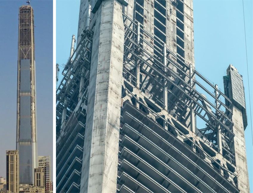
198                              Kyoung Sun Moon | International Journal of High-Rise Buildings

height over 1 km in Jeddah is under construction at pres-         toward mile-high towers. It reviews first the structural sys-
ent to surpass the Burj Khalifa soon. Based on the oil            tems for the world’s tallest buildings of different periods
wealth, the Middle East has rapidly become a new region           beginning from the emergence of supertall buildings in the
for tall, supertall and megatall (over 600 m) buildings.          early 1930s to the present. It also studies performances of
   At the time of the completion of the Empire State Build-       some of the major structural systems for extremely tall
ing, there were only two supertall buildings in the world.        contemporary buildings over 0.5 km and up to about 1
Both of them were in New York. When the Sears Tower               km. Finally, this paper investigates the potential of super-
was constructed, the number of supertall buildings increa-        framed conjoined towers for mile-high and even taller
sed to seven, four in New York and three in Chicago.              buildings.
Today, there are more than 100 supertall buildings in the
world. While majority of tall buildings are built in Asian        2. Structural Developments in Supertall
and Middle Eastern countries, new tall buildings are also            Buildings
continuously soaring up in the U.S. as well as many other
parts of the world in recent years. Indeed, tall buildings are      The Empire State Building of 1931 structured with the
now a global architectural phenomenon.                            braced moment resisting frames, the only available struc-
   There are many reasons why the number of tall build-           tural system for supertalls and already conventional at the
ings is continuously increasing and they are becoming             time of its construction, held the title of the world’s tallest
ever taller. The world population grows continuously, and         for longer than 40 years. Beginning from the mid-1960s
today more people live in urban areas than in rural areas.        and 1970s, various new structural systems more efficient
Only 30% of the world’s population was urban in 1950;             than the traditional braced moment resisting frames were
at present 55% of the world’s population resides in urban         continuously developed for an ever-increasing number of
areas in 2018; and the urban population will be further           supertall buildings. Today, some of the structural systems
increased to about 70% by 2050 according to the Popula-           efficiently produce even megatall buildings.
tion Division of the United Nations Department of Econ-
omic and Social Affairs. Tall buildings are one of the most       2.1. Structural Systems for Tallest Buildings
viable solutions to deal with this global phenomenon (Al-           Table 1 shows structural systems used for tallest build-
Kodmany and Ali, 2012).                                           ings in the world during different periods since the Empire
   Certainly, developments of tall buildings are not always       State Building. The moment resisting frame with lateral
based on their necessity and/or feasibility. Some tall build-     wind bracings around the building’s core was the predo-
ings are developed taller than necessary to express the           minantly used structural system for tall buildings includ-
city’s and/or country’s growing economic power. Some              ing the Empire State Building before the development of
other tall buildings are built as corporate or individual         the tubular concept by Fazlur Khan in the 1960s. Though the
aspirations. And there are many other non-feasibility-based       shear truss-frame interaction behavior was not fully under-
cases of tall building developments. Nonetheless, tall            stood at that time (Ali, 2001), engineers still recognized
buildings are still one of the most essential building types      the efficiency of adding diagonal bracings around the core
for the rapidly-urbanizing future world with dense cities;        which together with the orthogonal moment resisting fra-
more tall buildings will be built continuously to accommo-        mes acted as vertical trusses. Therefore, tall buildings with
date ever-growing urban population; and they will become          these braced moment resisting frames could be constructed
taller and taller to redistribute the urban density toward        more efficiently compared to those structured only with
the limitless space in the sky (Ali and Moon, 2007; 2018).        moment resisting frames. The structural steel use for the
Indeed, one of the greatest architects of all time Frank          102-story Empire State Building was 42.2 psf (206 kg/
Lloyd Wright already proposed a mile-high (1.6 km) tower          m2). It is noted that though no 100-story tall building was
about 60 years ago as a visionary project (Wright, 1957).         ever built only with moment resisting frames, Khan esti-
With a tower over 1 km already under construction, visio-         mated the steel use of about 65 psf (317 kg/m2) for this
nary mile-high and even taller buildings will perhaps no          imaginary case in his “premium for height” diagram (Khan,
longer be only a dream.                                           1970).
   There are many design issues to be considered to build           The framed tube as the firstly conceived tube system
extremely tall buildings not only regarding the towers            was employed for the first time in a reinforced concrete
themselves but also about the infrastructures around them.        building, the 43-story Dewitt-Chestnut Apartments of 1966
While all of the interrelated design issues should be holis-      in Chicago. Soon after, the system was employed for the
tically orchestrated, one of the most fundamental design          new tallest building in steel, the demolished 110-story One
considerations for exceedingly tall buildings is their struc-     World Trade Center which initiated the new supertall era
tural systems which make their physical existence possible.       41 years after the construction of the Empire State Build-
Though many structural systems have been developed, no            ing. Only two years after the completion of the One World
mile-high towers have actually been built yet. This paper         Trade Center, the 25 m taller 108-story Sears Tower (now
presents developments of tall building structural systems         called Willis Tower) was built with the bundled tube sys-
Developments of Structural Systems Toward Mile-High Towers                                199

Table 1. Structural systems for tallest buildings in the world since 1931
                                                                   Height
               Building                      City         Tallest Period  Story       Structural System
                                                                    (m)
       Empire State Building        New York       1931-1972        381    102 Braced Moment Resisting Frame
One World Trade Center, Demolished  New York       1972-1974        417    110          Framed Tube
  Sears Tower (now Willis Tower)     Chicago       1974-1998        442    108          Bundled Tube
          Petronas Towers          Kuala Lumpur    1998-2004        452     88          Tube-in-Tube
             Taipei 101               Taipei       2004-2010        508    101         Core-Outrigger
            Burj Khalifa              Dubai       2010-present      828    163         Buttressed Core
           Jeddah Tower               Jeddah    2021, expected - ? 1000+ 167           Buttressed Core

Figure 1. Height race: architectural heights vs. occupied heights of the tallest buildings.

tem which reduced the shear-lag induced inefficiency of          supertall buildings have been built in Asia. The tallest
the framed tube system. The steel uses for the One World         building was also built in Asia for the first time. The 452
Trade Center and Sears Tower were 37.0 psf (181 kg/m2)           m tall 88-story Petronas Towers of 1998 in Kuala Lumpur
and 33.0 psf (161 kg/m2) respectively (Schueller, 1990).         exceeded the architectural height of the Sears Tower by
These developments of tubular systems resulted in more           10 m. However, one of the most fundamental architectural
efficient tallest building structures compared to the Empire     design criteria is to provide occupiable spaces for people,
State Building. Another important tube system is the bra-        and it is noted that the tallest building in that regard was
ced tube employed for the 100-story John Hancock Cen-            still Sears Tower with its tallest occupied height 38 m
ter of 1969 in Chicago. This building used only 29.7 psf         taller than that of the Petronas Towers. The world’s tallest
(145 kg/m2) structural steel. Though the braced tube, more       height of the Petronas Towers was accomplished by des-
efficient than the framed or bundled tube in general, is in      igning and constructing the spires as integral parts of the
fact one of the most efficient structural systems for tall       main structures of the towers.
buildings, interestingly, it was never used for the tallest         In terms of structural materials, unlike all the other pre-
building of any period.                                          vious tallest buildings structured with steel, the Petronas
  Since the completion of the Sears Tower in 1974 no             Towers were built with reinforced concrete and steel res-
supertall buildings were built in any place of the world         ulting in composite structures. Since the beginning of the
until the construction of the 367 m tall Bank of China of        Asian era of tall buildings, reinforced concrete alone or in
1990 in Hong Kong. This is about the time when the most          combination with steel has widely been used for struc-
active tall building development region moved from the           tural systems of tall buildings not only in Asia but glob-
U.S. to Asian countries. Since the 1990s, many tall and          ally. The primary lateral load resisting system for the Pet-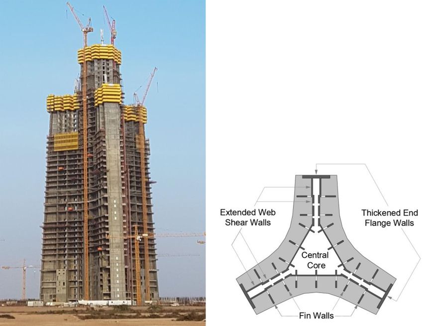
200 Kyoung Sun Moon | International Journal of High-Rise Buildings
ronas Towers is the tube-in-tube composed of the rein- ing larger for the tallest buildings, it will be only about 50
forced concrete core and perimeter framed tube. Due to m between the Burj Khalifa and Jeddah Tower.
the diversity in materials use, direct efficiency compari-
sons between tall building structures have become inapp- 2.2. Structural Systems for Tall Buildings over 500 m
ropriate. In 2004, the 508 m tall 101-story Taipei 101 fin- Taipei 101 reached the height of 500 m for the first time
ally reached the height of 0.5 km for the first time. With in 2004; the Burj Khalifa reached the height of 800 m in
its tallest occupied height at 438 m, it also exceeded the 2010; and finally the Jeddah Tower will exceed the height
tallest occupied height of the Sears Tower by 20 m. The of 1 km soon. As the accelerated height race has been
core-outrigger system, which became very popular from occurring so fast in recent years, many tall buildings have
the 1990s, was employed for Taipei 101 using reinforced been built, under construction, or proposed in the height
concrete and steel, resulting in composite structure. range between Taipei 101’s about 500 m and Burj Khalifa’s
In addition to Asia, Middle East has even more recently 800 m. It is important to take a close look at these build-
become one of the most active regions of tall building ings’ structural systems together with the recent tallest
developments. Dubai alone with its 37 supertall buildings buildings to better understand major lateral load resisting
either completed or under construction at present is the systems for the group of these exceedingly tall contem-
city having the largest number of supertalls in the world. porary buildings over 500 m.
Almost all of the supertalls already in use in Dubai were Table 2 shows most 500+ m tall buildings completed,
completed in the 21st century including the current world’s under construction or on hold, based on the database by
tallest Burj Khalifa. With its height of 828 m, it exceeded Council on Tall Buildings and Urban Habitat (CTBUH).
the height of the previous tallest Taipei 101 by a signifi- Only four towers in the considered height range and status
cant margin of 320 m. The Y-shaped plan form-integrated are omitted due to an inadequate amount of available struc-
reinforced concrete “buttressed core” system was employed tural information on them. The table also includes one
for the Burj Khalifa to reach the unprecedented enormous proposed tower whose structural design has well been
height. developed instead. With these 16 towers, several major
However, it is also noted that the tallest occupied height structural systems employed for today’s supertall and
difference between the Burj Khalifa and Taipei 101 is only megatall buildings of this extreme height range are identi-
147 m. As the height of the tallest building becomes grea- fied.
ter, the gap between the architectural and occupied heights The core-outrigger system has been one of the most pre-
also becomes larger. The Jeddah Tower, which also emp- valently used structural systems for the height range up to
loys the buttressed core system, will finally become the about 700 m either alone or in combination with other sys-
first tallest building exceeding the height of 1 km. It took tems. The braced megatube is also a very recent trend em-
about 120 years for tall buildings to reach the height of 0.5 ployed for 500+ m tall buildings mostly under construc-
km. However, it is expected that additional 0.5 km will be tion in combination with core or core-outrigger structures.
reached within less than just 20 years. As the difference The buttressed core system is used especially for recent
between the architectural and occupied heights is becom- megatall buildings over 600 m and up to 1 km. The subse-
Table 2. Structural systems for 500+ m tall buildings
Height
Building City Year Story Structural System
(m)
Jeddah Tower Jeddah Under Constr. 1000+ 167 Buttressed Core + Fin Walls
Burj Khalifa Dubai 2010 828 163 Buttressed Core + Fin Walls (w/ Outrigger)
Suzhou Zhongnan Center Suzhou On Hold 729 137 Core-Outrigger + Megaframe
Merdeka PNB118 Kuala Lumpur Under Constr. 644 118 Core-Outrigger + Braced Megatube
Signature Tower Jakarta Proposed 638 113 Core-Outrigger + Megaframe
Wuhan Greenland Center Wuhan Under Constr. 636 126 Buttressed Core-Outrigger
Shanghai Tower Shanghai 2015 632 128 Core-Outrigger
Ping An Finance Center Shenzhen 2016 599 115 Core-Outrigger + Braced Megatube
Goldin Finance 117 Tianjin Under Constr. 597 128 Braced Megatube + Core
Lotte World Tower Seoul 2017 555 123 Core-Outrigger
One World Trade Center New York 2014 541 94 Core + Perimeter Moment Resisting Frame
Guangzhou CTF Finance Centre Guangzhou 2016 530 111 Core-Outrigger
Tianjin CTF Finance Centre Tianjin Under Constr. 530 97 Core + Perimeter Sloped Column Frame
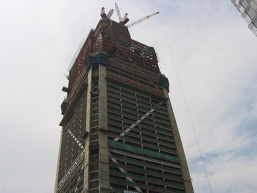
Citic Tower (formerly China Zun) Beijing Under Constr. 528 108 Braced Megatube + Core
Evergrande IFC T1 Hefei Under Constr. 518 112 Core-Outrigger + Megaframe
Taipei 101 Taipei 2004 508 101 Core-Outrigger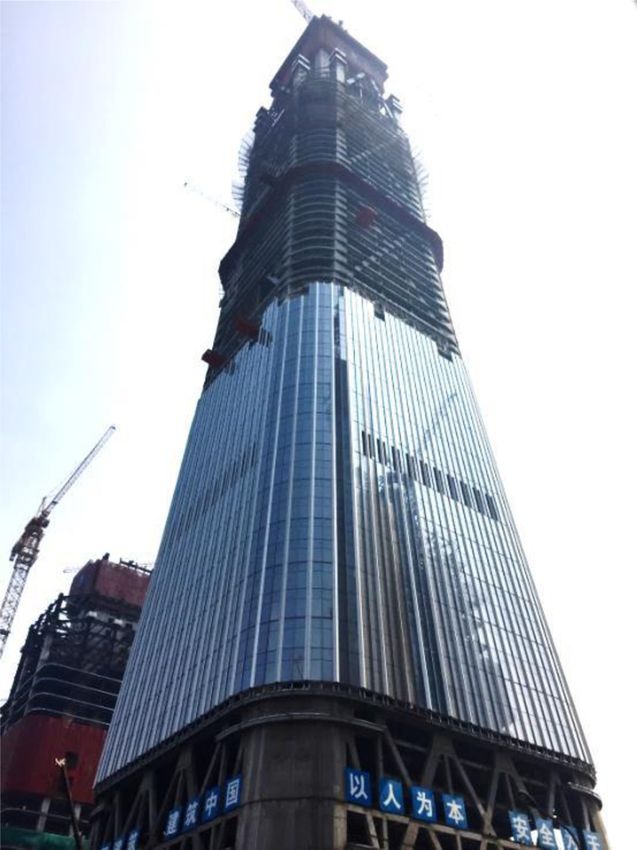
Developments of Structural Systems Toward Mile-High Towers                              201

Figure 2. Architectural heights vs. occupied heights of 500+ m tall buildings.

quent sections of this paper discuss these structural sys-       about 700 m.
tems in more detail. There are also some secondary sys-
tems such as perimeter megaframes and moment resisting           3.1. Core-Outrigger Systems
frames.                                                             Compared with structural cores with no outriggers, core-
   The substantial differences between the architectural and     outrigger systems carry wind-induced overturning mom-
occupied heights are also well observed in the 500+ m            ents more efficiently with greater structural depth by con-
tall buildings. While their architectural heights range from     necting perimeter megacolumns to stiff building cores
about 500 m to 1000 m, their occupied heights range from         through outriggers. Though core-outrigger structures are
about 400 m to only 600 m. The differences between the           also possible by only connecting regular perimeter columns
highest architectural and occupied heights become even           with belt trusses at the outrigger levels, supertall and
larger as buildings become taller as owners wish to extend       megatall outrigger structures almost always employ mega-
the height of their buildings with so-called “vanity heights”    columns for greater efficiency. The core-outrigger system’s
by employing integrally built structural spires (Ali and         lateral load carrying mechanism is conceptually explained
Moon, 2018). In this era of pluralism in architectural des-      in Fig. 3. The overturning moment (Mo) caused by wind
ign, many recent supertall heights are often more monum-         loads (W) is reduced due to the counteracting moment
ental than practical compared to those of the 1970s before       (Mc) provided by the megacolumns. The counteracting
the postmodern period.                                           moment Mc can be expressed in terms of the building width
                                                                 and cross-sectional area of the megacolumns as shown in
3. Core-Outrigger, Braced Megatube, and                          Eq. (1) (Moon, 2016).
   Mixed Systems                                                            2
                                                                    Mc = 2b AEχ                                           (1)
  As presented in the previous section, the core-outrigger
and braced megatube systems are two major structural               A is the cross-sectional area of the megacolumns; b is
systems employed for tall buildings over 500 m. In Table         the distance between the center of the core and perimeter
2, the core-outrigger and braced megatube appear nine            megacolumns on the outrigger plane; E is the modulus of
and four times respectively either alone or in combination       elasticity of steel; and χ is the curvature of the structure
with other systems. Further, the core-outrigger and braced       as a vertical cantilever bending beam. In steel structures,
megatube systems are sometimes directly combined toge-           for example, since the modulus of elasticity of steel is con-
ther with shared perimeter megacolumns, resulting in a           stant regardless of its strength, the outrigger structure’s
mixed system. This section studies further these structural      bending stiffness is a function of the square of the distance
systems frequently used for extremely tall buildings up to       between the center of the core and perimeter megacolumns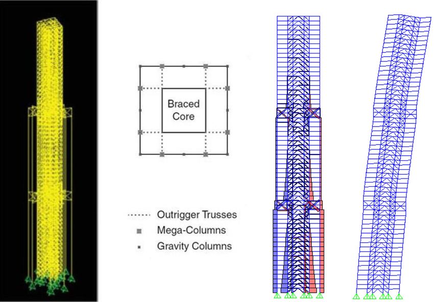
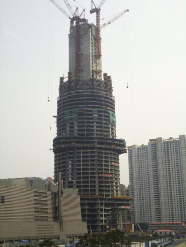
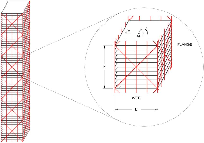
202                             Kyoung Sun Moon | International Journal of High-Rise Buildings

Figure 3. Simplified load carrying mechanism of the core-outrigger system.

as well as cross-sectional area of the megacolumns.
   The outriggers, generally in the form of trusses in steel
structures or walls in reinforced concrete structures, eff-
ectively act as stiff headers inducing a tension-compress-
ion couple in the perimeter megacolumns. Optimal loca-
tions of outriggers to minimize the lateral deformation
have been investigated by many researchers and engin-
eers. For the optimum performance, the outrigger in a one
outrigger structure should be at about half height; the out-
riggers in a two outrigger structure should be at about
one-third and two-thirds heights; the outriggers in a three
outrigger structure should be at about one-quarter, one-
half, and three-quarters heights, and so on (McNabb and
Muvdi, 1975; Smith and Coull, 1991).
   One of the earliest applications of the core-outrigger
system with perimeter megacolumns can be found in the
190 m tall 47-story Place Victoria Building (now called
Stock Exchange Building) of 1964 in Montreal. The out-
rigger system also appeared in Fazlur Khan’s structural
systems charts for steel tall buildings (Khan, 1973). How-
ever, he recommended the system for tall buildings up to
only about 60 stories as the outriggers stretching from the
core to the perimeter megacolumns as an alternate to only
belt trusses with regular perimeter columns were not yet         Figure 4. Shanghai Tower during construction showing cen-
fully investigated at that time, despite that the Place Vic-     tral core, belt trusses and perimeter megacolumns (photog-
toria Building had already been constructed with mega-           raph by Kyoung Sun Moon).
columns.
   Today, core-outrigger structures have been applied for
much taller supertall and megatall buildings as shown in         taller than Khan’s suggested height. There are multiple
Table 2. At present, the tallest building structured with the    reasons for this. As already discussed, today’s outrigger
core-outrigger system is the 632 m tall 128-story Shang-         structures typically use perimeter megacolumns for greater
hai Tower in Shanghai (Fig. 4). Furthermore, the system          efficiency instead of simply connecting regular perimeter
has already been applied to an even taller building currently    columns with belt trusses. In addition, the efficiency of
on hold, the 729 m tall 137-story Suzhou Zhongnan Cen-           the system is further increased economically in many
ter in Suzhou (Shen, 2014). These heights are significantly      cases by using steel and reinforced concrete composite
Developments of Structural Systems Toward Mile-High Towers                               203

Figure 5. Axial force diagram and deformed shape of core-outrigger system subjected to wind loads.

structures for both the interior core and megacolumns.          today’s tall buildings. The 555-m tall Lotte Tower in Seoul
Moreover, structural optimization in terms of the number        shown in the table was once proposed as a diagrid struc-
and locations of outriggers, etc., using today’s specialized    ture before its design was changed to the core-outrigger
parametric engineering software increases the system’s          system.
efficiency. Nonetheless, the structural efficiency of the          The studied buildings’ plan dimensions are 36 m × 36 m
core-outrigger system cannot exceed that of some of the         with 18 m × 18 m central cores, and their typical story
most efficient tube type structures such as braced tubes        height is 3.9 m. The height-to-width aspect ratios of the
and diagrids. However, another reason why the core-             60-, 80-, and -100 story buildings are 6.5, 8.7, and 10.8,
outrigger system is used for very tall buildings sometimes      respectively. All the required lateral stiffness of the braced
even taller than those tube type structures is that it is       tube and diagrid structures is allocated to the perimeter
architecturally more flexible on façade design.                 braced tubes and diagrids, and the core structures are des-
   Fig. 5 shows lateral performance of a 60-story outrigger     igned to carry only gravity loads. In the outrigger struc-
structure with two outriggers at one-third and two-thirds       tures, the core structures are steel braced frames, which
heights of the building. As the vertically cantilevered         carries not only gravity but also lateral loads. Outrigger
braced core bends due to lateral loads, outrigger trusses       trusses are located at every 20 stories over the building
connected to the core and the perimeter megacolumns             height except at the top.
provides resistance against the bending deformation. Cur-          The document, SEI/ASCE 7, Minimum Design Loads
vature reversals around the outrigger truss locations shown     for Buildings and Other Structures, is used to establish the
in the deformed shape clearly show this resistance. As can      wind load. The buildings are assumed to be in Chicago
be seen from the figure, the performance of the core-out-       and the basic wind speed of 40.2 meters per second (90
rigger system greatly relies on the core whose structural       miles per hour) is used. One percent damping is assumed
depth is much narrower than that of the building width.         for the calculation of the gust effect factor. Stiffness-based
Therefore, the structural efficiency of the core-outrigger      design is performed for each structure to meet the target
system cannot exceed that of the braced tubes or diagrids       maximum allowable lateral displacement of a five hund-
which use the entire building width as their structural         redth of the building height. Structural steel is used for all
depths and carry wind loads by axial actions of the peri-       three systems in this simplified comparative design study
meter tube members.                                             though reinforced concrete or composite structures are also
   Fig. 6 shows comparative lateral efficiency of the core-     very commonly used in today’s tall buildings.
outrigger, braced tube and diagrid systems based on design         As buildings become taller, there is a “premium for hei-
studies with 60-, 80-, and 100-story tall buildings struc-      ght” due to lateral loads and the demand on the structural
tured with these three different structural systems (Moon,      system increases not linearly but exponentially. Fig. 6,
2014). Braced megatube which will be discussed in more          which shows the required amount of structural steel for
detail later is a modified version of the braced tube for       the 60-, 80- and 100-story buildings of the core-outrigger,
greater efficiency. Though not appearing in Table 2, dia-       braced tube, and diagrid structures, clearly illustrates this
grids are another prevalently used structural system for        phenomenon. Though outrigger structures are efficient
204                              Kyoung Sun Moon | International Journal of High-Rise Buildings

Figure 6. Required amount of structural steel for 60-, 80- and 100-story tall buildings of core-outrigger, diagrid and braced
tube structures.

Figure 7. Braced tube structure composed of 10-story modules.

structural systems for tall buildings, the all-steel outrigger    3.2. Braced Megatubes
structures studied here are clearly less efficient than the          Braced tube structural systems are typically configured
tube type structures with large perimeter diagonals. The          with evenly spaced columns and large diagonals on the
reasons why the core-outrigger structures are still even          building perimeter. Fig. 7 shows a 60-story building struc-
more prevalently used for supertall and megatall build-           tured with the braced tube system composed of 10-story
ings than the tube type structures have already been dis-         tall modules in which V is wind-induced lateral shear force
cussed. Certainly, efficiency alone is not what determines        and M is overturning moment applied to the modules. Eq.
the structural systems for tall buildings. Many other design      (2) expresses the typical braced tube module’s bending
issues should carefully be considered holistically.               stiffness based on the perimeter columns on both the flange
Developments of Structural Systems Toward Mile-High Towers                             205

and web frames (Moon, 2010).                                      1.1 and 1.6, respectively. As the column arrangement bec-
                        2                                         omes denser toward the building corner, the web frame
                  B Ac E
  KB = (Nc, f +δ )--------------
                               -                          (2)     columns’ contribution to the bending stiffness increases,
                       2h
                                                                  and vice versa. This phenomenon has a direct impact on
   KB is bending stiffness; Nc,f is number of columns on          the lateral displacement of each tower. The maximum lat-
each flange frame (frame perpendicular to wind); δ is con-        eral displacements at the top of Case 1, 2 and 3 are 78.2
tribution of columns on web frames (frame parallel to wind)       cm, 76.0 cm and 73.4 cm respectively, based on SAP2000
for bending stiffness; B is building width in the direction       analyses.
of wind; Ac is cross-sectional area of each column; E is             William LeMessurier’s study on supertall structures dealt
modulus of elasticity of steel; h is module height.               with a similar topic (Rastorfer, 1985). Regarding overturn-
   In braced tubes, overturning moments and lateral shear         ing moments, the configuration with only four corner
forces due to wind loads are primarily carried by the peri-       megacolumns produces the greatest bending stiffness than
meter columns and diagonal bracings respectively. There-          any other column configurations when the same amount
fore, as the column arrangement is changed, the bending           of structural materials are used for each different alterna-
stiffness of the braced tube is also changed. Fig. 8 shows        tive. LeMessurier’s theoretical study of the 207-story tall
100-story braced tube structures whose perimeter columns          Erewhon Center used four corner megacolumns in com-
are configured in four different ways. Compared to the            bination with X bracings between them. This configura-
braced tube structures with their plan dimensions of 36 m         tion shown as Case 4 in Fig. 8 is conceptually the most
× 36 m studied in the previous section, the plan dimen-           extreme version of Case 3. While Case 1, 2 and 3 are
sions in this study are increased to 54 m × 54 m in order         composed of 24 perimeter columns on each floor, Case 4
to better study design alternatives with various column           has only four corner megacolumns. The cross-sectional
spacings. All the other design conditions are the same as         area of each column of Case 4 is six times larger than that
before. Case 1, 2 and 3 in Fig. 8 show three different            of each perimeter column of the other cases on each floor.
column spacing cases. In Case 1, the column spacing is            Therefore, the amount of structural materials used for all
gradually increased toward the building corner; in Case 2,        four cases are identical. Case 4, as the most extreme ver-
the columns are evenly spaced at every 9 meters; in Case          sion of Case 3, is much stiffer than the other cases. The
3, the column spacing is gradually reduced toward the             maximum lateral displacement of Case 4 with four corner
building corner. The value of δ for Case 1, 2 and 3 is 0.7,       megacolumns is only 58.0 cm, about 25% smaller than

Figure 8. Maximum lateral displacements of braced tube structures of various column configurations.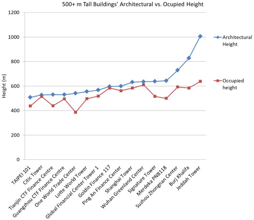
206                             Kyoung Sun Moon | International Journal of High-Rise Buildings

that of Case 2 with 24 evenly spaced columns. Though             of carrying gravity loads, there are additional small gravity
Case 4 provides greater lateral stiffness based on higher        columns between the corner megacolumns. The gravity
bending rigidity, however, one important issue of this case      loads in these gravity columns are transferred to the mega-
is that it requires a more sophisticated gravity load resis-     columns through the belt trusses installed between the
ting system because the dead and live loads of each floor        megacolumns at every about 15 stories in relation to the
must be carried also by the four corner megacolumns              structure’s module height as similarly predicted by Khan.
spaced at 54 meters in this particular example.                  The connections between the gravity columns and transfer
                                                                 belt trusses are made in such a way that the progressive
  “The ultimate possible improvement of the structural
                                                                 collapse can be prevented when some of the gravity col-
efficiency is to go from a multi-column concept to a square
                                                                 umns within the module are seriously damaged. The gra-
tower having only four large corner columns. …… This
                                                                 vity columns between the transfer belt trusses are provided
then is the ultimate high-rise steel building. It means that
                                                                 with vertically slotted connections with the top trusses.
at every 20 floors or so there would be transfer trusses
                                                                 Therefore, these columns supported by the bottom trusses
……, thereby guaranteeing that all gravity loads in the
                                                                 carry the floor loads entirely by compression in normal
building flow into the four corner columns.”
                                                                 cases, but some of the columns toward the top trusses
                                        Fazlur Khan, 1972
                                                                 change to tension columns when any column failure occurs
   Khan, who engineered the first braced tube supertall          within the module (Liu et at., 2012).
John Hancock Center of 1969, already envisioned a struc-            While the arrangement of corner megacolumns estab-
tural configuration similar to what is shown in Case 4 of        lishes one of the most efficient lateral load- resisting sys-
Fig. 8 as “the ultimate possible improvement of the struc-       tems, it could be obstructive for viewing from the interior
tural efficiency.” Further, he also conceived the idea of        corner spaces often the most desired in the building. In
transfer trusses between the corner megacolumns to carry         the 528-m tall 108-story Citic Tower (formerly known as
gravity loads (Khan, 1972).                                      China Zun), currently under construction in Beijing, the
   This idea of a modified braced tube with corner mega-         braced megatube concept was also used. However, the
columns and a reasonably good solution for transferring          corner megacolumns of the Citic Tower are split into two
gravity loads has been employed for recent supertall build-      following the rounded square-shaped floor plans on almost
ings, and they are classified as braced megatubes in this        all levels to provide column-free corner space, except for
paper. In the 597-m tall 128-story Goldin Finance 117 cur-       only several lowest levels near the base where the maxi-
rently under construction in Tianjin, four corner megacol-       mum overturning moments are applied (Fig. 10). Though
umns in conjunction with large perimeter diagonal brac-          the configuration with paired megacolumns around the
ings carry lateral loads very efficiently (Fig. 9). In terms     corners does not provide the same level of stiffness prov-

Figure 9. Goldin Finance 117 under construction showing the braced megatube composed of corner megacolumns, large
perimeter X-bracings, gravity columns and transfer belt trusses (photographs in public domain).
Developments of Structural Systems Toward Mile-High Towers 207
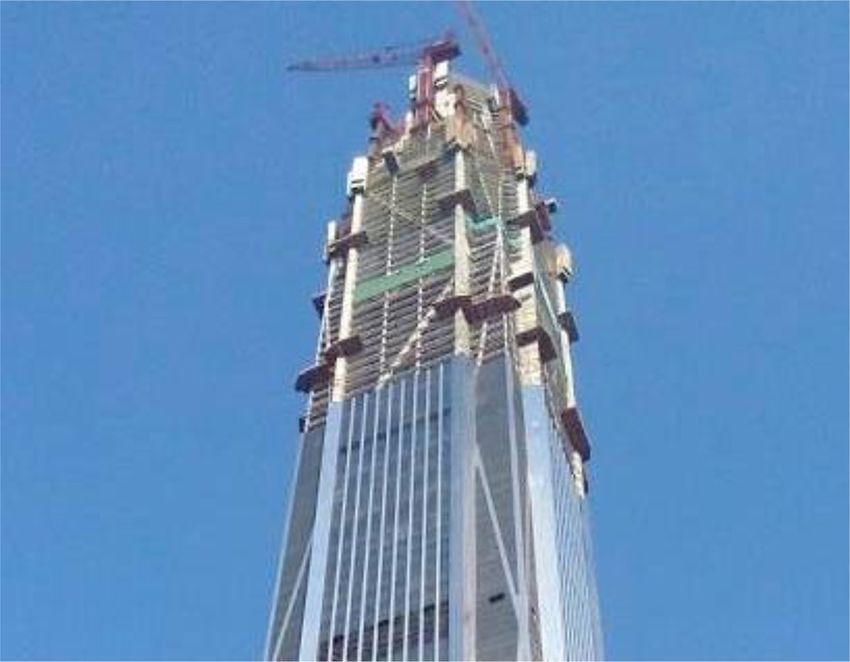
Figure 10. Citic Tower under construction showing single corner megacolumns on several lowest levels and split paired
corner megacolumns on typical levels (photograph in public domain).
ided by single corner megacolumns when the same amo- the megacolumns. Fig. 11 also shows a mixed system with
unts of structural materials are used, it produces more des- four corner megacolumns and diagonally rearranged outri-
irable architectural result. The configuration of the gravity ggers as is the case with the Shanghai World Financial
columns and transfer belt trusses in the Citic Tower is very Center shown in Fig. 12. Alternatively, the mixed system
similar to that in the Goldin Finance 117. can be designed with eight megacolumns. In this case, the
outriggers can be configured orthogonally as usual, but the
3.3. Mixed Systems bracings should be placed between the eight megacolumns,
Combining two (or possibly more) lateral load resisting which results in some edge bracings directly meeting at
systems in tall buildings is not new. Different from the the corners. An example of this case is the Ping An Fin-
traditional combined systems such as shear wall (or shear ancial Center shown in Fig. 13.
truss)-frame interaction system and tube-in-tube system, The 492-m tall 101-story Shanghai World Financial
however, in some of the new supertall and megatall struc- Center of 2008 in Shanghai is one of the earliest mixed
tural systems, major components of the lateral load-resist- system examples. This building, originally designed as a
ing systems combined are shared, resulting in mixed sys- 460-m tall, had been structured with a tube-in-tube sys-
tems in which the shared components consequently carry tem with the reinforced concrete core and steel framed
out dual functions to meet project-specific design require- tube system, and foundation piles had already been in
ments. Such systems are often produced in recent tall build- place based on this design when its design was changed
ings when the previously studied core-outrigger and braced to a 492-m tall building with larger plan dimensions. To
megatube systems are directly combined with shared mega- accommodate these changes without reconstructing the
columns by the both systems. existing foundation system, more efficient structural system
When common squarish floor plans are considered, a had to be developed for not overloading the foundation.
core-outrigger system is typically configured with two As a solution, the perimeter framed tube was changed to
megacolumns on each of four sides totaling eight, while a more efficient braced megatube, and consequently, the
a braced megatube is designed with four corner mega- thickness of the concrete core walls and hence the weight
columns as shown in Fig. 11. Therefore, some adjustments could be reduced. In addition, outrigger trusses were added
are often necessary to mix these two systems by sharing that connected the core and corner megacolumns diago-208 Kyoung Sun Moon | International Journal of High-Rise Buildings Figure 11. Concept of mixed system composed of typical core-outrigger and braced megatube systems with shared corner megacolumns and diagonally rearranged outriggers. Figure 12. Shanghai World Financial Center during construction showing central core, corner megacolumns, perimeter dia- gonals, and belt trusses; diagonally arranged outriggers are hidden inside (photograph in public domain). nally (Katz and Robertson, 2008). As a result, an unpre- load resisting systems for very tall buildings with shared cedented mixed system was developed with the core-out- megacolumns. rigger and braced megatube systems, two major lateral Since the construction of the Shanghai World Financial
Developments of Structural Systems Toward Mile-High Towers                               209

Figure 13. Ping An Finance Center during construction showing central core, two megacolumns on each side, perimeter
diagonals, and belt trusses; outriggers are hidden inside (photograph in public domain).

Center, some of the supertall buildings have employed a             This type of mixed system is still relatively new and
similar structural system. These buildings include the           other types of new mixed systems are also in use for some
599-m tall 115-story Ping An Financial Center of 2016 in         other supertall buildings. In the Signature Tower in Jakarta
Shenzhen and the 644-m tall 118-story Merdeka PNB118             and Suzhou Zhongnan Center in Suzhou, core-outrigger
which is currently under construction in Kuala Lumpur            structural systems are used as the primary lateral load
(Fender et al., 2016). The performance of this type of           resisting system. In the core-outrigger system, the belt
mixed system composed of the two major tall building             trusses are typically placed at the outrigger levels. In these
structural systems is greatly influenced by stiffness distri-    buildings, however, additional belt trusses are placed
bution between them. It could be designed as a core-out-         mostly between the outrigger levels. Consequently, the
rigger-system-dominant structure with supplemental stiff-        megacolumns in combination with the belt trusses placed
ness provided by the braced megatube as is the case with         more densly than usual form so-called megaframes (Wij-
the Ping An Financial Center. This approach particularly         anto et al., 2012). Therefore, the megacolumns are also
in this building was driven by the relatively recent seismic     shared in these cases between the core-outrigger and peri-
design requirements of the local building code regarding         meter megaframe systems. Without perimeter diagonals,
perimeter structures introduced in 2010 (Poon and Gott-          however, the stiffness of the orthogonal perimeter mega-
lebe, 2017), which did not exist at the time of the design       frame is comparatively limited, and consequently it is
and construction of the previously discussed Shanghai            almost always a secondary system.
World Financial Center.                                             Indeed, these as well as more mixed systems are possi-
   Alternatively, the mixed system of this combination           ble and different stiffness distributions between the com-
could also be designed to have a much stiffer braced             ponent systems may result in different structural perform-
megatube. As the stiffness of the exterior tube is increa-       ance characteristics even though they will still look very
sed, the effectiveness of the outrigger trusses will be          similar. The decision making regarding these issues is dep-
decreased compared to the core-outrigger-system-domin-           endent on the various project-specific design requirements.
ant mixed structure. When the stiffness of the exterior tube     Deriving an optimal structural solution based on not only
is configured to exceed that of the core eventually, the effi-   structural but also all the other related aspects for each
ciency of adding the outrigger trusses will be minimal.          project is up to the collaborative efforts of the architects
Then, the system could be reconfigured to the conventio-         and engineers.
nal tube-in-tube system instead without outrigger trusses
as are the cases with the previously presented Goldin Fin-       4. Structural Systems for Tall Buildings over
ance 117 and Citic Tower. They could also remain to pro-            1 km
vide greater level of redundancy for enhanced safety and
still add some limited stiffness.                                   For extremely tall buildings, structural systems cannot
210                             Kyoung Sun Moon | International Journal of High-Rise Buildings

be configured independently without considering building         of the wings and shear walls into them, desired structural
forms. In order to maintain structural efficiency, it is imp-    depths against wind loads can also be obtained. This design
ortant to keep reasonable height-to-width aspect ratios for      strategy results in the buttressed core system shown in
extremely tall buildings such as those whose heights are         Fig. 14.
close to or even over 1 km. In order to maintain reason-            Second, multiple extremely tall and slender buildings
able height-to-width aspect ratios, the width of the build-      of reasonable spatial depths can be structurally conjoined
ing has to become larger as a building becomes taller, and       at multiple locations over the building height. In this way,
this condition makes very deep interior space uncomfort-         the structural depth of the tower complex can significantly
able for users, especially due to the lack of natural day-       be increased to the depth of the group of the conjoined
light, when typical squarish plans are used. In order to         towers. This scheme results in superframed conjoined
resolve this issue, two different design strategies can be       towers shown also in Fig. 14. While the buttressed core
considered.                                                      system involves a significant limitation in architectural
   First, building plans can be configured to have multiple      plan forms to perform structurally as intended. Plan forms
wing spaces of reasonable spatial depths branched from           of the individual tall buildings of the superframed conjo-
the central area. Building cores are also configured to          ined towers are less limited. Instead, the distances and
have a central structural core and its extensions as shear       structural connections between the towers substantially
walls into the wing spaces to better structure this type of      influence the architectural design of the superframed con-
overall plan configuration. Then, by extending the length        joined towers.

Figure 14. Buttressed core and superframed conjoined towers with simplified plans showing their structural and architectural
design concepts.
Developments of Structural Systems Toward Mile-High Towers                                211

4.1. Buttressed Core Systems                                     the wing spaces are further stiffened by additional shear
   Both the tallest at present and soon-to-be tallest build-     walls called “fin walls” perpendicular to them with outri-
ings employ the buttressed core structures. These extre-         ggers or through deep coupling walls as in the Burj Khal-
mely tall buildings have three wings in combination with         ifa and Jeddah Tower respectively for necessary openings
tapered forms for better architectural and structural perf-      in the fin walls, which often also act architecturally as int-
ormances. Three winged Y-shaped tall buildings are not           erior demising walls.
new though they are more common recently. The 197-m                 Though the architecture-integrated buttressed core sys-
tall Lake Point Tower of 1968 in Chicago with its central        tem provides efficient structures with increased structural
triangular concrete core is one of the early examples. The       depths, flexibility in interior space use is limited to a large
264-m tall Tower Palace Three of 2004 in Seoul is another        degree due to the specific forms required. However, within
example of more recent Y-shaped tall buildings also with         the overall mass of vertically extruded Y-shape, creating
its triangular concrete core engaging virtual outrigger sys-     varied exterior building forms can be done without much
tem to increase its structural depth against lateral loads.      difficulty as the extended shear walls can be terminated in
As the height of the Y-shaped tall buildings becomes ext-        various different ways without transfer structures. They are
reme in the 828 m tall Burj Khalifa of 2010 and the 1000+        terminated to create spirally stepping or smoothly tapering
m tall Jeddah Tower currently under construction, the cen-       forms in the Burj Khalifa and Jeddah Tower respectively.
tral core itself is further extended as shears walls into the    These tapered forms provide superior structural perform-
architectural spaces of the three wings.                         ances in terms of not only static but also dynamic wind
   The extended shear walls from the central core to form        responses by disturbing organized vortex shedding over
the buttressed core structures are terminated with thick-        the building height. In tall buildings, vortex shedding-
ened flange walls perpendicular to the extended shear            induced lock-in phenomena causing resonances often
walls around or at the end of the wings as can be seen in        create the most critical structural design conditions. Vortex-
Fig. 15. These thickened end flange walls are comparable         shedding frequency is directly related to wind velocity,
to the flanges of a vertical cantilever beam with Y-shaped       Strouhal number, and plan dimensions of the building.
cross section, while the extended shear walls are like their     Thus, tapered forms with continuously changing plan dim-
webs (Tamboli, 2014). Therefore, the buttressed core sys-        ensions help tall buildings prevent shedding organized
tem could be understood as extended core shear walls with        alternating vortices over the building height. Therefore,
thickened end flange walls to efficiently structure the Y-       the benefit of flexibility in easily creating varied tapered
shaped plan form buildings. The extended shear walls to          building forms could be significant.

Figure 15. Jeddah Tower under construction (photograph in public domain) and its simplified structural plan showing central
core, extended shear walls, thickened end flange walls, and fin walls.
212                             Kyoung Sun Moon | International Journal of High-Rise Buildings

4.2. Superframed Conjoined Towers toward Mile-High
Cities
   Fazlur Khan renowned for his tube structures also dev-
eloped his idea of superframe for the unbuilt 168-story
tall Chicago World Trade Center (Ali, 2001). In Khan’s
superframe with a square plan form, four trussed L-shape
corner megacolumns are interconnected by multistory
trusses at every about 20 stories over the building height.
By conceptually expanding and modifying Khan’s idea of
superframe for a multiple tower complex, superframed
conjoined towers can be developed. Conjoined supertall
towers are a relatively new architectural phenomenon.
When the superframe idea is applied to interconnected
three or more conjoined towers, their heights can be inc-
reased very efficiently by structurally connecting the
towers. In superframed conjoined towers, braced tube
buildings are located at each corner of the conjoined tower
complex and interconnected by multistory horizontal bra-
ced tube structures. These horizontal braced tubes are
what create the superframed conjoined tower structure            Figure 16. Lateral displacement profiles of 100-story bra-
which uses the entire width of the conjoined tower com-          ced tubes stand-alone and structurally conjoined (elevation
plex as the structural depth instead of the width of the         view of SAP2000 3D models).
individual towers. Therefore, the stiffness of the horizontal
connection braced tube structures, which in a sense perform
like link beams in much smaller scale coupled shear wall         displacement scale factor of 50 is used in this figure. In
structures, is a very important structural design consider-      the right image, two of the braced tube structures are con-
ation.                                                           joined with horizontal braced tube structures. Though the
   The left image of Fig. 16 shows lateral displacement          actual wind loads these towers are subjected to in the dir-
profile of the 100-story braced tube structure studied in        ection of the connections will be complicated, the two
section 3-1 in comparison with the outrigger structure. A        towers are loaded with code-defined winds in this simpli-

Figure 17. Mile-high superframed conjoined tower design project.
Developments of Structural Systems Toward Mile-High Towers 213
fied and conservative comparison study. It is clear that the 1885 in Chicago is considered by many as the origin of
lateral stiffness of the conjoined towers in the direction of tall buildings of skeletal structures. It took only about 45
the connections is much greater than that of the individual years for this new building type to grow into a ten times
tower due to the structurally linking horizontal braced taller building of the 381 m tall 102-story Empire State
tubes. Building of 1931 in New York. About 25 years later, Frank
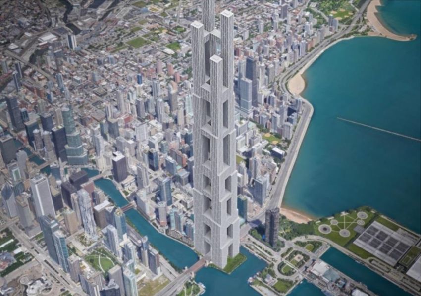
Fig. 17 shows a mile-high superframed conjoined tower Lloyd Wright proposed his mile-high ILLINOIS in 1957,
design project by Chris Hyun at Yale School of Architec- a visionary tower about four times taller than the Empire
ture under the guidance of the author. The project was State Building. In his mile-high ILLINOIS, Wright even
proposed for the empty site in Chicago partly including envisioned to provide rentable space in the final tier of
the area once used for the never-completed Chicago Spire the building up to 528th floor. Considering these extre-
project by Santiago Calatrava. In this design project, four mely rapid developments of tall buildings including the
exceedingly tall buildings are interconnected with the visionary one in the past, their current status is, in fact, not
structural concept of superframe to create mile-high con- comparable.
joined towers. The exceedingly tall buildings presented in this paper
Four braced tube towers are placed in the corners of the are certainly astonishing achievements. Despite that it has
enormous superframe allowing it to reach the height of been almost 90 years since the construction of the Empire
one mile (1.6 km). The braced tube towers are intercon- State Building and 60 years since the proposal of the
nected by horizontally linking braced tube structures of mile-High ILLINOIS, however, even the tallest Burj Kha-
multiple story height, which become the structural and lifa reached only about a half mile. The height of the soon-
architectural connections between the towers housing to-be tallest Jeddah Tower of about 1 km is also still quite
potentially sky lobbies and other public spaces of truly below one mile. These gaps are even severer when the
city-like conjoined mega-towers. By structurally intercon- occupied height is considered. Therefore, though it is said
necting multiple towers, greater structural depths as a by many that we are now very close to reaching mile-high
group against lateral loads for an enormous height and towers, we have reached only a fraction toward it yet esp-
desired lease depths for individual towers for better func- ecially in terms of the occupied height. For comfortable
tional performances can be achieved simultaneously. The and sustainable mile-high occupancies, developing tech-
individual towers are tapered through multiple setbacks nologies and designs further beyond what we have reached
toward the top creating varying lease depths for different so far is essential.
functions placed at different heights. At the same time,
the stepped tapering helps reduce both static and dynamic References
wind responses of the towers as discussed earlier. The
placements of the structurally linking horizontal braced Al-Kodmany, K. and Ali, M. M., 2012. The Future of the
tubes are denser toward the base where the maximum City: Tall Buildings and Urban Design, WIT Press, U.K.
overturning moments are applied. Ali, M. M., 2001. Art of the Skyscraper: The Genius of Faz-
Despite its characteristics much appropriate for extremely lur Khan, Rizzoli International Publications, New York,
tall buildings, the architecture-integrated structural concept NY.
Ali, M. M. and Moon, K., 2007. “Structural Developments
of superframed conjoined towers may not be easily emp-
in Tall Buildings: Current Trends and Future Prospects,”
loyed for existing dense urban land because very large
Architectural Science Review Journal, Vol. 50.3, pp. 205-
building sites are required for them. However, where app- 223.
ropriate, these towers may be a viable solution for the Ali, M. M. and Moon, K., 2018. “Advances in Structural
problem of dense urban environments, by way of creating Systems for Tall Buildings: Emerging Developments for
mile-high vertical cities toward the sky. Contemporary Urban Giants,” Buildings, 2018, 8(8), 104;
doi:10.3390/buildings8080104.
5. Conclusions Arup, 2018. Arup’s Tall Buildings in Asia: Stories behind the
Storeys. Lodon and New York: Routledge.
This paper has reviewed structural systems for the tall- Baker, W., Besjak, C., McElhatten, B., and Biswas, P., 2009.
est buildings of different periods as well as for today’s “555m Tall Lotte Super Tower, Seoul, South Korea,” Proc-
most tall buildings over 500 m either completed or under eedings of Structures Congress, Austin, TX, April 30 -
May 2.
construction. Performances of some of the major structural
Boake, T. M., 2014. Diagrid Structures: Systems, Connect-
systems for these extremely tall buildings, such as core-
ions, Details, Birkhauser Verlag, Basil, Switzerland.
outrigger, braced megatube, mixed, and buttressed core Connor, J. J., 2003. Introduction to Structural Motion Control.
structures have also been studied. Further, the potential of New York: Prentice Hall.
superframed conjoined towers has been investigated as a Council on Tall Buildings and Urban Habitat (CTBUH), 2015.
viable solution where appropriate for future mega-towers 100 of the World’s Tallest Buildings. Images Publishing
creating mile-high cities. Group, Mulgrave.
The 42 m tall 10-story Home Insurance Building of Council on Tall Buildings and Urban Habitat, 2015. Tall Build-You can also read


