Multi-view data capture for dynamic object reconstruction using handheld augmented reality mobiles
←
→
Page content transcription
If your browser does not render page correctly, please read the page content below
Noname manuscript No.
                                         (will be inserted by the editor)

                                         Multi-view data capture for dynamic object reconstruction
                                         using handheld augmented reality mobiles
                                         Matteo Bortolon · Luca Bazzanella · Fabio Poiesi
arXiv:2103.07883v2 [cs.MM] 20 Mar 2021

                                         Received: date / Accepted: date

                                         Abstract We propose a system to capture nearly-             1 Introduction
                                         synchronous frame streams from multiple and moving
                                         handheld mobiles that is suitable for dynamic object 3D     Dynamic objects recorded from multiple viewpoints can
                                         reconstruction. Each mobile executes Simultaneous Lo-       be digitally reconstructed to produce free-viewpoint
                                         calisation and Mapping on-board to estimate its pose,       videos (FVV), or 4D videos, which can then be ex-
                                         and uses a wireless communication channel to send or        perienced in Augmented or Virtual Reality [34, 38, 33].
                                         receive synchronisation triggers. Our system can har-       Multi-view 3D/4D reconstruction and understanding
                                         vest frames and mobile poses in real time using a de-       of dynamic objects is challenging because it requires
                                         centralised triggering strategy and a data-relay archi-     cameras to be calibrated in space and time [26, 22, 14,
                                         tecture that can be deployed either at the Edge or          31, 32, 11]. The 4D reconstruction task in uncontrolled
                                         in the Cloud. We show the effectiveness of our sys-         scenarios for real-time applications (e.g. telepresence)
                                         tem by employing it for 3D skeleton and volumetric          is particularly challenging as it requires accurate cam-
                                         reconstructions. Our triggering strategy achieves equal     era synchronisation, calibration and communication to
                                         performance to that of an NTP-based synchronisation         operate seamlessly on commodity hardware [40, 31].
                                         approach, but offers higher flexibility, as it can be ad-   FVV is sensitive to frame-level synchronisation inac-
                                         justed online based on application needs. We created        curacies because frame misalignments may cause 3D
                                         a challenging new dataset, namely 4DM, that involves        reconstruction artifacts. For controlled setups, frame-
                                         six handheld augmented reality mobiles recording an         level synchronisation can be achieved using shutter-
                                         actor performing sports actions outdoors. We validate       synchronised cameras [31]. However employing this ap-
                                         our system on 4DM, analyse its strengths and limita-        proach in uncontrolled environments with conventional
                                         tions, and compare its modules with alternative ones.       mobiles is unrealistic. Also, camera calibration must be
                                                                                                     guaranteed at frame level in order to triangulate 2D fea-
                                                                                                     tures in 3D over time when handheld mobiles are used.
                                         Keywords Free-viewpoint video · 4D video · 3D               Typically, with static cameras, an expert operator uses
                                         reconstruction · Synchronisation · Augmented Reality        a checkerboard or a calibration wand to estimate intrin-
                                                                                                     sic and extrinsic parameters prior to the data capture
                                                                                                     [14]. With moving cameras, an option can be to ex-
                                         M. Bortolon and L. Bazzanella                               ploit (external) static cameras to compute the extrinsic
                                         Universitá degli Studi di Trento                            parameters of the moving ones [22]. However, this ap-
                                         Trento, Italy                                               proach is also unrealistic in uncontrolled environments
                                         E-mail: matteo.bortolon@studenti.unitn.it                   as it requires an ad-hoc setup. Lastly, to avoid frame
                                         E-mail: luca.bazzanella-2@studenti.unitn.it
                                                                                                     transmission delays or drops due to packet buffering,
                                                                                                     bandwidth congestions should be carefully handled [11].
                                         F. Poiesi (corresponding author)
                                         Technologies of Vision, Fondazione Bruno Kessler                In this paper, we propose the first mobile-based
                                         Trento, Italy                                               system that is designed for multi-view dynamic ob-
                                         E-mail: poiesi@fbk.eu                                       ject reconstruction in natural scenes using commodity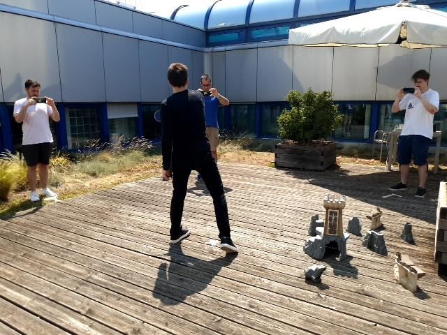
2 Matteo Bortolon et al.
5 4 3D pose reconstruction
hardware (Fig. 1). Our setup employs multiple mobiles 3
2
that can estimate their own pose on-board in real time
6
via Simultaneous Localisation and Mapping (SLAM). 1
We use ARCore’s SLAM implementation running on
the Android mobiles [1]. A host mobile must be the volumetric reconstruction
initiator of a capture session. A set of client mobiles
can then join this session by connecting to the host.
Mobiles can capture nearly-synchronous frames and
their respective poses using wireless communications
(e.g. 802.11, 5G). The host uses synchronisation trig-
gers to inform the clients when to capture frames and
their respective poses. To mitigate inter-mobile com-
munication delays, we use a delay compensation strat-
egy to temporally align host and clients’ frame cap- 3 2 1
tures through an artificial delay that is applied to the
frame capturing after the arrival of the trigger. Each
mobile applies a different delay that is based on its own
round trip time (RTT) with respect to the host and
4 5 6
on the largest RTT measured by all the mobiles. We
experimentally show that our synchronisation trigger- handheld mobile synchronously captured frames WiFi comms
ing strategy equals the performance of an NTP-based Fig. 1 Six people recording an actor from different view-
approach [30], but offers the advantage of being more points with their augmented reality-enabled mobiles. Our
flexible, as the trigger frequency can be changed online system can synchronously capture mobile poses and camera
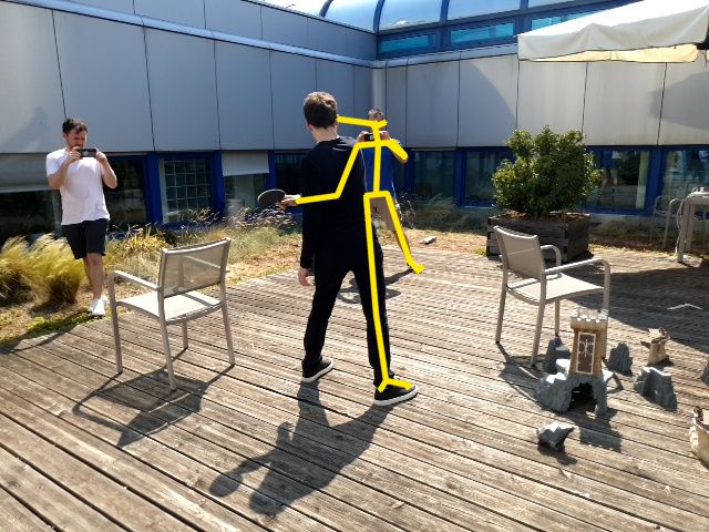
based on application needs. We collected a new outdoor frames from the mobiles, thus allowing applications such as
3D skeleton reconstruction or volumetric reconstruction. Mo-
dataset, namely 4DM (4DMobile), which involves an biles communicate through conventional wireless connections
actor performing sports actions that we recorded using (e.g. 802.11, 5G).
six handheld augmented reality mobiles. To show that
our system is effective for dynamic object reconstruc-
tion, we implemented and evaluated two challenging ap- introduces delays that are non-deterministic. SLAM
plications, namely temporal 3D skeleton and volumet- runs on top of the Unity3D rendering engine, needed
ric reconstructions. In the former, we reconstructed the by the UI/UX to provide guidelines to the users dur-
3D skeleton of the actor by triangulating its 2D poses ing the frame capture, thus leading to irregular time
estimated on each mobile image plane. In the latter, intervals between consecutive frames;
we reconstructed the volume of the person from their – A system that significantly extends our previous
2D silhouettes. Fig. 1 shows an example of our results. work [11]: we re-designed the module in charge of
The source code and the 4DM dataset are avalilable at managing frame streams in real time, making it
https://github.com/fabiopoiesi/4dm. more efficient, and implemented two new applica-
In summary, the novelties of our work are: tions to assess the quality of the captured data;
– A dataset (4DM) for 4D object reconstruction that
– A mobile-based system to reconstruct dynamic ob- we collected using six consumer handheld aug-
jects in natural scenes that can be deployed using mented reality mobiles in natural scenes. Unlike
commodity hardware. Unlike [22], our system does [22], 4DM is captured with consumer mobile cam-
not require manual camera calibration; eras. Unlike [10], the mobile poses are estimated in
– A delay compensation strategy to allow nearly- real time using SLAM. Unlike [41], 4DM includes
synchronous data captures from multiple viewpoints scenes captured with intentionally unstable hand-
for wirelessly-connected mobiles. Unlike [34], which held cameras.
uses an ultra-bright LED flash and synchronises
frames in post-processing, we do not use specialised The paper is organised as follows. Sec. 2 presents re-
hardware. Unlike [9], which operates on the camera lated work about low-latency immersive computing and
sensor directly and exploits the mobile hardware im- free-viewpoint video production. Sec. 3 formulates the
age streaming, our synchronisation problem is more problem we aim to tackle. Sec. 4 describes the design of
challenging because the captured frames have to be our mobile-based system to capture near-synchronous
synchronised with their corresponding mobile poses frames and mobile poses. Sec. 5 describes the applica-
and across mobiles, and because the SLAM process tions we implemented to validate our system. Sec. 6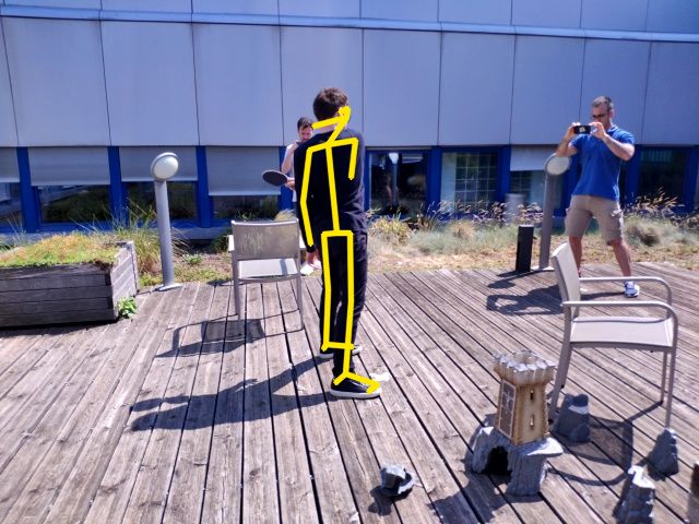
Multi-view data capture for dynamic object reconstruction using handheld augmented reality mobiles                      3

presents the analysis of the experimental results. Sec. 7     training data of the same type as the observed 3D ob-
draws conclusions.                                            jects, for example from video games [39]. Traditional
                                                              FVV (i.e. non-CNN) approaches can be based on shape-
                                                              from-silhouette [16], shape-from-photoconsistency [42],
2 Related work
                                                              multi-view stereo [40] or deformable models ([20].
                                                              Shape-from-silhouette aims to create 3D volumes (or vi-
Low-latency immersive computing: To foster im-
                                                              sual hulls) from the intersections of visual cones formed
mersive interactions between multiple users in aug-
                                                              by 2D outlines (silhouettes) of objects visible from mul-
mented spaces, low-latency computing and communi-
                                                              tiple views. Shape-from-photoconsistency creates vol-
cations must be supported [48]. FVV is very sensitive
                                                              umes by assigning intensity values to voxels (or volu-
to synchronisation issues and computations must be ex-
                                                              metric pixels) based on pixel-colour consistencies across
ecuted as close to the user as possible to reduce lag.
                                                              images. Multi-view stereo creates dense point clouds by
    Synchronisation can be achieved using hardware- or
                                                              merging the results of multiple depth maps computed
software-based solutions. Hardware-based solutions in-
                                                              from multiple views. Deformable model-based methods
clude timecode with or without genlock [22], and Wire-
                                                              aim to fit known reference 3D models to visual ob-
less Precision Time Protocol [15]. Genlock is robust
                                                              servations, e.g. 2D silhouettes or 3D point clouds. All
to drifts, but needs specialised network components.
                                                              these methods need frame-level synchronised cameras.
Hardware-based solutions are not our target, as they
                                                              [45] describes a spatio-temporal bundle adjustment al-
require important modifications to the communication
                                                              gorithm to jointly calibrate and synchronise cameras.
infrastructure. Software-based solutions can be offline
                                                              Because it is a computationally costly algorithm, it is
or online. Offline solutions can use Spatio-Temporal
                                                              desirable to initialise it with reliable camera poses and
Bundle Adjustment (ST-BA) to jointly compute the en-
                                                              synchronised frames. Amongst these methods, multi-
vironment structure while temporally aligning frames
                                                              view stereo produces reconstructions that are geomet-
[45]. However, ST-BA is a post-process with compu-
                                                              rically more accurate than the other alternatives, albeit
tational overhead, hence unsuitable for real-time ap-
                                                              at a higher computational cost. Approaches like shape-
plications. Online solutions can use the Network Time
                                                              from-silhouette and shape-from-photoconsistency are
Protocol (NTP) to instruct devices to capture frames
                                                              more suitable for online applications as they are fast,
periodically while attempting to compensate for delays
                                                              but outputs have less definition. We implemented a
[24,46, 9]. Cameras can share timers that are updated
                                                              proof-of-concept shape-from-silhouette method based
by a host camera [46]. Software solutions, if combined
                                                              on the frames and the mobile camera poses that are
with ad-hoc hardware control, can achieve state-of-the-
                                                              captured with our system.
art synchronisation accuracy [9]. Although NTP ap-
proaches are simple to implement, they are unaware of
situational context. Hence, the way in which clients are      3 Problem formulation
instructed to capture images in a session is totally dis-
connected from scene activity. These clients are unable       Let C = {cj }C j=1 be a set of C handheld mobiles. Let fi,c
to optimise acquisition rates either locally or globally,     be the ith frame captured by camera c ∈ C. fi,c is an im-
prohibiting optimisation techniques such as [36], that        age composed of N pixels X = {xn }N     n=1 , where xn ∈ R
                                                                                                                         2
                                                                        th                     3×3
aim to save bandwidth and maximise output quality.            is the n pixel. Let Kc ∈ R           be the camera matrix
Our solution operates online and is aimed at decentral-       (intrinsic parameters), Ri,c ∈ R3×3 be the camera rota-
ising synchronisation supervision, thus is more appro-        tion and ti,c ∈ R3 be the camera translation (extrinsic
priate for resource-efficient, dynamic-scene capture.         parameters) with respect to each camera’s local refer-
Free-viewpoint video production: Free-viewpoint               ence. R0,c = I 3×3 and t0,c = [0, 0, 0]T , where I 3×3 is
(volumetric or 4D) videos can be created either through       a 3×3-identity matrix and T is the transpose operator.
the synchronised capturing of objects from differ-            Let Pi,c = [Ri,c |ti,c ], Pi,c ∈ R3×4 , be the mobile pose.
ent viewpoints [16, 31], or with Convolutional Neural         Each mobile is globally localised through a transforma-
Networks (CNN) [39] that estimate unseen content.             tion Tc ∈ R3×4 that maps Pi,c to a global reference. Let
The former strategy needs camera poses to be esti-            Di,c = {fi,c , Pi,c , σi } be the data retrieved by c upon
mated/known for each frame, using approaches like             the arrival of the synchronisation trigger (or trigger )
SLAM [50] or by having hardware-calibrated camera             σi . σi is uniquely identified through an identifier. Each
networks [31]. Typically, estimated poses lead to less-       c aims to synchronously capture Di,c and transmit it in
accurate reconstructions [40] when compared to cali-          a timely manner to a central computing node. The goal
brated setups [31]. Conversely, CNN-based strategies          of our system is to retrieve Di,c ∀c ∈ C in real time and
do not need camera poses, but instead need synthetic          to use Di,c to generate 4D videos.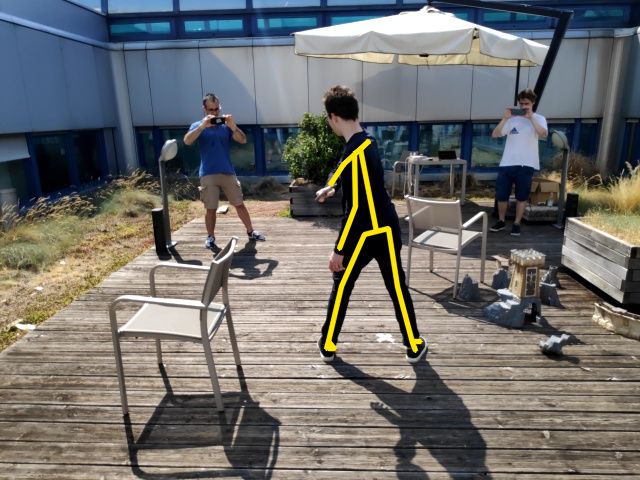
4                                                                                                                Matteo Bortolon et al.

                                      edge
                                                                             video. The latency between host and clients can in-
                                                              3D/4D
           Google
             Cloud                relay     data
                                                          reconstruction     crease depending on the transmission distance, the net-
           Platform              server    manager
        Unity3D                                            visualisation     work traffic, and the interference with other networks
         Match
        Making
                                frames and meta-data           application   [44]. Therefore, latency must be analysed and compen-
                      router
                                               local network                 sated for [45]. We use a latency compensation strategy
         router       switch                                                 where the host measures the Round Trip Time (RTT)
Fig. 2 Block diagram of the proposed data-capture system,                    between itself and the clients, and communicates to
which involves a mobile host (the initiator of a capture ses-                each client the delay they must apply when capturing
sion), a set of mobile clients (the participants), a Relay Server            Di,c . The host builds a matrix L ∈ RA×B , where the
to handle synchronisation triggers and a Data Manager to                     element la,b is the bth measured RTT between the host
process the data. Mobiles communicate with Cloud services
only to initiate the capture session.                                        and the ath client. B is the number of RTT measure-
                                                                             ments and A=C-1 is the number of clients. The host
                                                                             computes the RTT for each client
4 Our mobile-based capture system
                                                                                     B
                                                                             ¯la = 1
                                                                                     X
                                                                                       la,b                                           (1)
Our data-capturing system mainly involves a mobile                                 B
                                                                                      b=1
host (the initiator of a capture session), a set of mobile
clients (the participants), a Relay Server to handle trig-                   and then computes the maximum RTT
gers and a Data Manager to process the data (Fig. 2).
                                                                             ` = max({¯l1 , ..., ¯lA })                               (2)
Mobiles aim to capture the data Di,c synchronously
from different viewpoints. To decide when to capture                         The ath client will capture data with a delay of
Di,c , the host generates triggers, rather than fixing the
                                                                                      1
rate beforehand on a central node. In this work we con-                      ∆ta =      (` − ¯la )                                    (3)
figured the host to send triggers at frequency φ. Note                                2
that a different policy for sending triggers can be imple-                   while the host will capture data with a delay of 21 `.
mented, e.g. triggers can be generated dynamically at
points that depend on the scene content. When the host
captures Di,c , a counter is incremented, and its value is                   4.2 Synchronisation relay
embedded in the trigger σi and used as a unique iden-
tifier. Di,c is then captured by each client after they                      To reduce the network traffic generated by trigger
receive σi .                                                                 counts and to promote deployment (e.g. 802.11, 5G),
                                                                             we design a Relay Server to forward triggers received
                                                                             by the host to the clients. Relay-based architectures
4.1 Session initialisation                                                   have the disadvantage of increased latency compared
                                                                             to peer-to-peer ones [19], but we practically observed
4.1.1 Global localisation                                                    that they ease deployment, especially in networks that
                                                                             use Network Address Translation. For timely delivery of
Mobiles independently estimate the environment struc-                        the triggers, we employ a relay mechanism that is typ-
ture and their pose Pi,c in real time through SLAM                           ically used for collaborative virtual environments [37]
[1]. Once each mobile has mapped its surroundings, the                       and teleoperation [49], namely MLAPI [5]. MLAPI uses
host computes the features to estimate the transforma-                       UDP to avoid delays caused by the flow-control system
tion Tc ∀c ∈ C. These features are sent to the Cloud,                        of TCP. Our Relay Server is based on the concept of
where they are processed to determine Tc [4]. Mobiles                        Multi-access Edge Computing and exploits the design
receive Tc and compute the mobile pose Pi,c  0
                                               = Tc ◦ Pi,c                   of MLAPI. Its architecture and synchronisation proto-
to globally localise themselves. ◦ is the composition op-                    cols are detailed in [11].
erator. Without loss of generality, we keep Tc ∀c ∈ C
fixed during the capture session.
                                                                             4.3 Data stream

4.1.2 Latency estimation                                                     Throughput linearly increases with the number of
                                                                             mobiles until network congestion is reached. We ob-
For a given σi , if mobiles undergo delay, the dynamic                       served that four mobiles transmitting at 10fps on
object may be captured with a different pose from dif-                       a conventional 2.4GHz WiFi suffice to reach maxi-
ferent viewpoints, thus affecting the quality of the 4D                      mum bandwidth. Although HTTP-based applications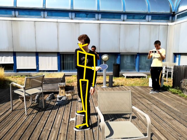
Multi-view data capture for dynamic object reconstruction using handheld augmented reality mobiles                                                             5

are network-agnostic, they are unreliable with large
                                                                            frame              frame              frame              frame
throughputs. When the maximum bandwidth capacity                       meta-data          meta-data          meta-data          meta-data

is reached, numerous HTTP-connections undergo time-                 serialise          serialise          serialise          serialise               frames
                                                                                                                                                       and
outs due to delayed or lost TCP packets. This leads                                                                                                   poses
to re-transmissions: more HTTP connections are cre-

                                                                                               ...
                                                                            ...

                                                                                                                  ...

                                                                                                                                      ...
                                                                                                                                             TCP
ated and more packets are dropped due to Socket buffer
overflows. Hence, triggers are not delivered (as they
                                                                    socket 1            socket 2          socket 3            socket 4
are UDP packets), leading to partial data captures. To                                                                                             merging
mitigate these problems, we design a Socket-based ar-             de-serialise        de-serialise      de-serialise        de-serialise

                                                                                                                                                   queue
chitecture that establishes a single connection between

                                                                                       queue

                                                                                                          queue
                                                                    queue

                                                                                                                             queue
each mobile and the Data Manager (Fig. 3). This al-
lows us to increase the percentage of successfully de-                       decoding thread                       decoding thread
                                                                                       cpu core                              cpu core
livered packets. Specifically, after Di,c is captured, the      data manager
frame fi,c is encoded in JPEG, as it provides the best
trade-off between compression and encoding/decoding            Fig. 3 Data (i.e. mobile poses and camera frames) is seri-
                                                               alised on each mobile and transmitted to the data manager
speed. Di,c is serialised [6], split into packets and trans-   via TCP socket. Using a multi-thread-based application, the
mitted to the Data Manager via TCP. Mobiles can                data manager de-serialises the data and checks for data con-
eventually buffer packets if they detect network conges-       sistency across what was received from the different mobiles
tions. Frames can also be video encoded to reduce the          via the merging operation. Captured data can be stored in a
                                                               database for further processing.
throughput, but this would require additional on-board
processing. Moreover, to our knowledge, there are no
video encoders that can embed metadata (like mobile            5.1 3D skeleton reconstruction
poses) positionable with frame precision within a video
stream. The Data Manager receives the packets, merges          We extract the body pose of each person in fi,c ∀c ∈
them to restore the (original) serialised message and          C [12, 47]. OpenPose [12] can be used to estimate the
de-serialises the message. De-serialisation can ingest up      2D skeleton of each person using up to 25 joints per
to 5282fps on a Xeon 3.1Ghz. We associate each de-             skeleton. Because O is typically viewed in close-up on
serialisation instance to a Socket. Frames are processed       each mobile and in the centre of the frame, for each
at 200fps by a verification module that checks their in-       fi,c we score each detection as the product between the
tegrity. We use a queue for each socket and perform            area of the bounding box enclosing the skeleton, and
verification using multiple threads. Because frames are        the inverse of the distance between the bounding box
often disordered after verification, we re-organise them       centre and the frame centre. We select the skeleton that
together with their meta-data (merging) before storing         is inclosed in the bounding box with max score. Let
them in a database.                                            Hi,c = {hm        m      2 M
                                                                          i,c : hi,c ∈ R }m=1 be the set of M ordered
                                                               skeleton joints (e.g. M =25) of O estimated in fi,c . hmi,c
                                                               is the position of the mth joint. We find the 3D joints by
                                                               triangulating the corresponding 2D joints from camera
                                                               pairs. To compute reliable 3D joints, we use the camera
                                                               pairs that have a predefined angle between their image
5 Validation applications                                      plane normals. Specifically, given a camera pair c, c0 ∈ C
                                                               such that c 6= c0 , the angle between their image plane
                                                               normals is defined as
We evaluate our system through two applications that
require synchronous frame captures, i.e. the 3D skeleton                                      n̂i,c · n̂i,c0
                                                               αi,c,c0 = cos−1                                     ,                                          (4)
reconstruction and the volumetric reconstruction af an                                    ||n̂i,c || · ||n̂i,c0 ||
actor over time. In the former we estimate the actor’s         where n̂i,c and n̂i,c0 are the image plane normals of cam-
skeleton joints in 2D on each camera image plane and           era c and c0 , respectively. We deem c, c0 a valid pair if
triangulate them in 3D. In the latter, we volumetrically       τα ≤ αi,c,c0 ≤ τα0 , where τα and τα0 are parameters. Let
reconstruct the actor using a shape-from-silhouette-           Γi = {{c, c0 } : c, c0 ∈ C, c 6= c0 } be the set of valid cam-
based approach [25] because the black clothes hinder           era pairs, ∀ {c, c0 } ∈ Γi we compute the set of visible
the extraction and matching of reliable and sufficient         3D joints. We denote the mth 3D joint computed from
feature points. We experienced this issue in our prior         {c, c0 } as
work [11]. Formally, let O be the actor. At each i we
                                                                 m           m      m          0         0

process Di,c ∀c ∈ C with the same trigger identity σi .        ωi,c,c 0 = t hi,c , hi,c0 , Kc Pi,c , Kc Pi,c0 ,            (5)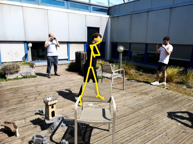
6                                                                                                          Matteo Bortolon et al.

where t(·) is a triangulation algorithm, e.g. the Direct             PointRend [23] as it provides superior performance in
Linear Transform algorithm (Sec. 12.2 in [17]).                      terms of silhouette segmentation to Mask R-CNN [18].
    Because each camera pair produces a 3D point for                 Let Ψi,c be the silhouette of O, which is selected at
each joint, we typically have multiple 3D points for the             each frame as in Sec. 5.1. We compute the volume of
                                                     0
same joint. Let Ωim = {ωi,c,c
                          m        m         3
                              0 : ωi,c,c0 ∈ R , {c, c } ∈ Γi }       O as Visual Hull (VH) [25], i.e. the intersection of C
                                      th                             visual cones, each formed by projecting each Ψi,c in 3D
be the set of 3D points of the m joint triangulated
from {c, c0 } and let Ωi = {Ωim }M   m=1 be the set of all
                                                                     through the camera centre of c [13]. Because finding vi-
triangulated 3D points. We seek a 3D point for each                  sual cone intersections of generic 3D objects is not triv-
joint to reconstruct the 3D skeleton. Let Si = {sm        i :
                                                                     ial, VH can be approximated by a set of voxels defining
sm       3 M
 i ∈ R }m=1 be the set of the skeleton’s 3D joints.
                                                                     a 3D volume [29]. Each voxel is projected on each cam-
We design a function g : Ωi → Si that transforms a                   era image plane and if its 2D projection is within Ψi,c for
set of 3D points into a single 3D point for each joint as            all c ∈ C then this voxel is considered to belong to O’s
follows. A 3D point seen from multiple viewpoints can                VH. In practice, due to noisy silhouette segmentation
be reliably computed by minimising the re-projection                 and/or noisy camera poses, one seeks if the voxel pro-
error through Bundle Adjustment (BA) [28] as                         jection is within a subset of silhouettes rather than all.
             M X
               C
                                                                     Let Vi = {νi,θ : θ = 1, . . . , Θ} be a set of voxels, where
arg min
             X
                       d(Q(ai,c , sm     m 2                         νi,θ ∈ R3 is the centre of the θth voxel approximating a
                                   i ), hi,c )                (6)
    Ai ,Si   m=1 c=1
                                                                     volume of size ∆ν × ∆ν × ∆ν and Θ is the total number
                                                                     of voxels. We fix ∆ν to keep the same spatial resolution
where Ai = {ai,c : c ∈ C} and ai,c is a vector whose ele-
                                                                     over time. Each νi,θ is projected on each camera’s im-
ments are the intrinsic and extrinsic parameters of cam-                                                                     0
                                  0
                                                                     age plane using the camera parameters Kc and Pi,c         for
era c at frame i, i.e. Kc , Pi,c     , respectively. Q(ai,c , sm
                                                               i )   each c. In our experiments we define a bounding volume
is the predicted projection of the joint m on view c,
                                                                     composed of 160×160×160 voxels occupying a space of
and d(x, y) is the Euclidean distance between the im-
                                                                     1.8×1.8×1.9 meters centred in the position of the 3D
age points represented by the inhomogeneous vectors x
                                                                     skeleton’s hip joint. Let xi,c,θ be the 2D projection of
and y. The solution of Eq. 6 is a new set of camera pa-
                                                                     νi,θ on c. If bxi,c,θ c ∈ Ψi,c , where b·c is the rounding to
rameters and 3D points. Without loss of generality we
                                                                     lower integer operation, then νi,θ is within the visual
keep the camera parameters fixed and let BA determine
                                                                     cone of c. If νi,θ is within the visual cone of at least
only the new 3D points. The non-linear minimisation of
                                                                     nΨ cameras, then we deem νi,θ to belong to O’s VH.
Eq. 6 requires initialisation. Snavely et al. [43] use the
                                                                     We post-process VH with Marching Cubes to find the
camera parameters and the 3D points triangulated from
                                                                     iso-surfaces and to produce the final mesh [27].
an initial camera pair as initialisation, then BA is exe-
cuted incrementally each time a new camera is added,
using the new solution as initialisation for the next step
(see Sec. 4.2 of [43]). This requires multiple iterations            6 Experimental results
of BA at each i. To reduce the processing time, we ex-
ecute BA globally, once for each i, using the centre of              6.1 Hardware and software
mass of each joint as initialisation. The mth centre of
mass is                                                              The mobile app is developed in Unity3D [7], using AR-
       (
            1
                P             m             m
                                                                     Core for SLAM [1] and the Cloud Anchor to find Tc
  m      |Ωim |   {c,c0 }∈Γi ωi,c,c0 , if Ωi 6= ∅                    [4]. Capture sessions are managed by Unity3D Match
µi =                                                           (7)
         0,                             otherwise                    Making [8]. The Relay Server and the Data Manager
                                                                     are embedded in separate Docker containers, running
where | · | is the cardinality of a set. If µm
                                             i = 0, it will
                                                                     on a laptop within the local network. In [11] we de-
not be processed by BA. The solution of Eq. 6 provides
                                                                     scribe our Relay Server architecture/protocols in detail.
Si . We will empirically show in Sec. 6.5 that initialising
                                                                     JPEG frames are serialised/deserialised using Protobuf
with the centres of mass can reduce the computational
                                                                     [6]. We use the Sparse Bundle Adjustment C-library
time and that BA converges to the same solution as
                                                                     [28]. To collect data, we used two Huawei P20Pro, one
using the incremental approach of [43].
                                                                     OnePlus 5, one Samsung S9, one Xiaomi Pocophone F1
                                                                     and one Xiaomi Mi8. Mobiles were connected to a 5GHz
5.2 Volumetric reconstruction                                        WiFi 802.11 access point. We used a Raspberry Pi 2 to
                                                                     route packets to the internet. Relay Server and Data
We extract the silhouette of each person in fi,c ∀c ∈                Manager are deployed on an Edge computer within the
C using instance-based segmentation [18, 23]. We use                 same local network as the mobiles.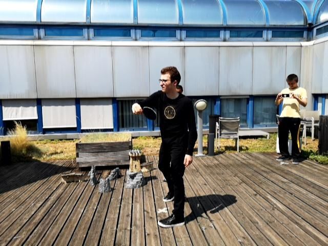
Multi-view data capture for dynamic object reconstruction using handheld augmented reality mobiles                         7

Table 1 Percentage of successfully received data comparing
architectures based on Socket and HTTP through Cloud and
Edge services under different WiFi connections.

                      Cloud              Edge
     Method
                  2.4GHz 5GHz        2.4GHz 5GHz
     HTTP [11]     45.1%    78.2%     38.8%    79.0%
     Ours          59.2%    78.6%     49.3%    77.7%

                                                              Fig. 4 Average and standard deviation time difference be-
                                                              tween consecutive frames received on the Data Manager as a
6.2 Dataset                                                   function of the trigger frequency and of the number of mo-
                                                              biles. Statistics are computed over three captures of 30s each.
We collected a dataset, namely 4DM, which involves six        The reference is the ideal case.
people recording a person acting table tennis (Fig. 1).
We recorded the 4DM dataset outdoors, with cluttered
                                                              6.4 End-to-end delay assessment
backgrounds, cast shadows and with people appear-
ing in each other’s view, thus becoming likely distrac-
                                                              To assess the end-to-end delay we used two mobiles
tors for object detection and human pose estimation.
                                                              configured in the same way as in 4DM. We adopted
We recorded three sequences: 4DM-Easy (312 frames,
                                                              the same procedure as [11] to quantify the frame cap-
all recording people were static), 4DM-Medium (291
                                                              ture delay between mobiles, i.e. two mobiles captured
frames, three recording people were moving) and 4DM-
                                                              the time ticked by a stopwatch (up to millisecond pre-
Hard (329 frames, all recording people were moving and
                                                              cision) displayed on a 60Hz computer screen (16ms re-
we added occluders to the scene). The host generated
                                                              fresh rate). We extracted the time digits from each pair
triggers at 10Hz. Frames have a resolution of 640×480
                                                              of frames captured by the two mobiles using OCR [2]
and an average size of 160KB. The latency between mo-
                                                              and computed their time difference. Frames that were
biles and the Relay Server was ∼5ms.
                                                              likely to provide incorrect OCR digits were manually
                                                              corrected. For each experiment, we used the first 100
                                                              captured frames and calculated the average and stan-
6.3 Throughput and latency                                    dard deviation of the difference between consecutive
                                                              frames. For comparison, we implemented the approach
We compare our Edge solution with a Cloud-based one,          proposed in Sec. IV of [9], i.e. the NTP is requested 50
i.e. AWS [3]. Tab. 1 shows the percentage of success-         times by each mobile and the average NTP over these
fully received data in the case of Socket and HTTP            requests is used as a global synchronisation between
based transmissions to the Cloud and to the Edge us-          mobiles. The clock of the mobiles is aligned to this esti-
ing 2.4GHz and 5GHz WiFi. The host generated trig-            mated global time and used to synchronise the capture
gers at 20Hz for one minute. HTTP is as effective as          of each frame. The host informs the other mobiles when
Socket when the bandwidth has enough capacity, but            to start the acquisition with respect to this estimated
unreliable when there is limited capacity. We observed        global time through a trigger. As we explained in Sec. 1,
that Socket-level data management is key to effectively       we cannot achieve a camera-sensor synchronisation as
manage large throughputs.                                     in [9], because the capture of frames and the associ-
     Fig. 4 shows the statistics of the time difference be-   ated mobile poses depends on the SLAM process and
tween consecutive frames received on the Data Manager         the Unity3D rendering engine. We name this approach
as a function of the trigger frequency and the num-           NTP-Sec. IV [9]. We also implemented a NTP base-
ber of mobiles. We used up to four mobiles connected          line version of NTP-Sec. IV [9], namely NTP-Baseline,
to a 2.4GHz WiFi. The host transmitted triggers at            where a single NTP request is used for the global time.
5Hz, 10Hz and 15Hz for 30 seconds. We associated a                Tab. 2 shows the comparison between our trigger-
reference time difference for each capture showing the        based synchronisation method and NTP-based synchro-
ideal case, e.g. 10Hz→0.10s. Experiments were repeated        nisation approaches. We empirically measured a stan-
three times for each capture. We can observe that when        dard deviation of about 16ms in all cases, correspond-
the network bandwidth is enough, the Data Manager             ing to the monitor refresh rate. The results show that
can receive frames at the same trigger frequency as           the synchronisation using our trigger-based method
that set by the host mobile. When the throughput ex-          achieves the same accuracy as that of NTP-based ap-
ceeds the bandwidth capacity, the system starts buffer-       proaches. Because triggers are generated by the host,
ing packets due to TCP re-transmissions.                      we can inherently vary their frequency online based on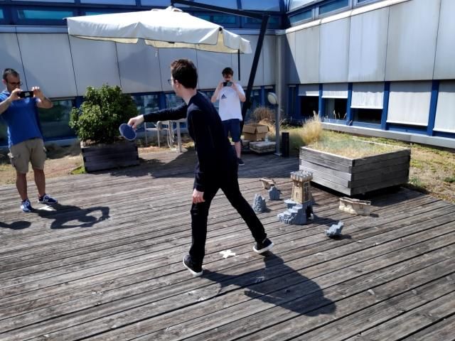
8                                                                                                     Matteo Bortolon et al.

Table 2 Statistics of the time differences measured between
frames captured by two mobiles using different synchronisa-
tion methods. We reported the statistics measured by [9] and
those we obtained using our OCR-based procedure.

                  Method             Avg ± Std [ms]

    Reported      Naive Wired            103 ± 50
                  Naive Bluetooth         69 ± 65
     by [9]
                  Naive Wifi             123 ± 84
    Measured      NTP-Baseline            29 ± 16
      by us       NTP-Sec. IV [9]         20 ± 16
    with OCR      Ours                    21 ± 17

                                                               Fig. 6 Comparison between Bundle Adjustment computed
the application requirements. For completeness, we also        incrementally [43] and globally. The re-projection error is re-
                                                               ported in pixels over time for 4DM-Easy, 4DM-Medium and
include the results reported in [9] in the case of mobiles     4DM-Hard.
synchronised without exploiting the prioritised camera
sensor access. The three “Naive” experiments used a
single button press to trigger both phones to capture
a frame each. The connectivity amongst mobiles was
established through an audio wire, a Bluetooth connec-
tion and peer-to-peer WiFi. Note that their measured
delays are much higher than ours.

6.5 3D skeleton reconstruction

Fig. 5 shows a sequence of 3D skeletons reconstructed
                                                               mobile 1             mobile 3              mobile 5
from 4DM-Easy, while Fig. 6 reports the re-projection
error using Eq. 7. The average re-projection error (over
time and across joints) is 2.86 pixels for 4DM-Easy, 2.64      Fig. 7 3D skeleton and mobile poses in 4DM-Hard. Three
                                                               zoomed-in frames overlaying the re-projected 3D joints (red
pixels for 4DM-Medium and 3.11 pixels for 4DM-Hard.
                                                               dots) and the 2D joints computed with OpenPose (green
We can observe that BA reaches the same solution as            dots).
the strategy in [43]. However, as shown in the legends
of Fig. 6, the global minimisation allows us to reduce
by more than thrice the computational time for each            joints computed with OpenPose (green dots). Some of
i. Fig. 7 shows the 3D skeleton and the mobile poses           the re-projected 3D points are shifted from the 2D lo-
in 4DM-Hard at i=164, and three zoomed-in frames of            cations estimated with OpenPose. We attribute these
the person captured from mobiles 1, 3 and 5, overlay-          errors to the mobile poses that may have been inaccu-
ing the re-projected 3D joints (red dots) and the 2D           rately estimated by SLAM due to the high dynamicity
                                                               of the scene (moving object and moving cameras), and
                                                               to synchronisation delays.
                                                                   To assess the robustness of our system, we sim-
                                                               ulated different miss-detection rates affecting Open-
                                                               Pose output on different numbers of cameras. Miss-
frame 20                     frame 23
                                                               detection implies that the actor is not detected, hence
                                                               the affected camera cannot contribute to triangulation.
                                                               Fig. 8 shows the average (line) and standard deviation
                                                               (coloured area) of the re-projection error. We can ob-
frame 26                     frame 29                          serve that miss-detections lead to an expected steady
                                                               increase in re-projection error. We did not encounter
Fig. 5 Sequence of frames of the reconstructed 3D skeleton     breaking points at which the system completely fails
from 4DM-Easy.                                                 triangulation. As long as a valid camera pair (Sec. 5.1)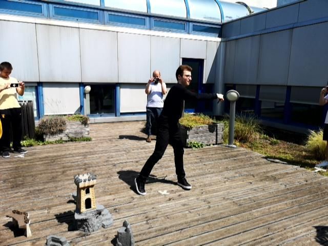
Multi-view data capture for dynamic object reconstruction using handheld augmented reality mobiles                            9

                                                               Table 3 Comparison between the 3D skeleton reconstructed
                                                               with our system and that estimated with VideoPose3D [35] in
                                                               terms of re-projection error (average and standard deviation
                                                               calculated over all the frames of each dataset).

                                                                                      Method             Avg ± Std [pixels]

                                                                      Hard Med Easy
                                                                                      VideoPose3D [35]     6.836 ± 1.303
                                                                                      Ours                 4.735 ± 1.195
                                                                                      VideoPose3D [35]     7.403 ± 1.130
                                                                                      Ours                 5.053 ± 1.072
Fig. 8 Sensitivity analysis showing the average (line) and                            VideoPose3D [35]     7.803 ± 1.218
the standard deviation (coloured area) of the re-projection                           Ours                 5.645 ± 1.316
error as a function of a simulated OpenPose’s miss-detection
rate affecting different numbers of cameras.

does not undergo miss-detections, the system can tri-
angulate the skeleton’s joints.
    BA can also jointly optimise camera parameters             infers 3D skeletons directly from 2D images. Video-
(i.e. mobile poses) and 3D points. Fig. 9 shows results        Pose3D processes the 2D joints computed on the im-
(at i=143 in 4DM-Hard) by applying BA on 3D points             ages of the whole sequence and outputs the respective
only, and on both 3D points and mobile poses. The av-          3D joints for each frame with respect to the mobile co-
erage re-projection error in this example is 5.35 pixels       ordinate system. VideoPose3D exploits the temporal in-
for the former and 2.23 pixels for the latter. The full se-    formation to generate 3D joint locations over time. The
quence is available in the supplementary video. Here we        input 2D joints are computed with Detectron2 [47]. Dif-
can observe that the 3D skeleton is estimated similarly        ferently from OpenPose, the skeleton model of Video-
in the two cases, but camera poses are different: they         Pose3D uses M =15 joints. We use a model pretrained
are often positioned in implausible locations. To further      on Human3.6M [21]. To make the results comparable,
investigate this issue, we fixed one mobile as world ref-      we input the same 2D joints estimated with Detectron2
erence and optimised the others in order to enforce BA         to our system.
to anchor the optimisation with respect to this mobile’s
pose (reference), without seeking a new coordinate re-
arrangement. However, we still experienced this unde-              Fig. 10 shows the overlay between the 3D skele-
sired behaviour. We believe that this happens for three        ton triangulated with our method (black), (a) the six
reasons. First, there are similar numbers of 3D points         3D skeletons estimated from each mobile with Video-
and camera parameters to optimise. This may hinder             Pose3D (green), and (b) the skeleton whose joints are
BA in converging to the correct solution, as the struc-        computed as the centres of mass amongst the cor-
ture of the environment has few 3D points. Second, mo-         responding joints inferred from all the mobiles with
biles may receive triggers with different delays. Delays       VideoPose3D (light blue). VideoPose3D’s output skele-
may vary based on the quality of the wireless connec-          ton is up to a scale. To overlay the skeleton obtained
tion: e.g. if an external user, within the same wireless       via triangulation with our system with that of Video-
network, generates traffic (e.g. downloads a file), they       Pose3D, we scaled VideoPose3D’s skeleton by making
will affect the network latency. Third, BA assumes 2D          the hip centres of the two skeletons coincide (see the
joints to be correct. Hence, if OpenPose fails to esti-        yellow spheres). VideoPose3D outputs a different torso
mate some joints, this will then affect the minimisation       and head’s representations of the input skeleton. There-
process. An example is in mobile 4 of Fig. 9, where the        fore we compute the re-projection error only for the
person behind the actor has affected OpenPose estima-          skeletons’ joints that exist in both input and output.
tion.                                                          VideoPose3D is an offline approach as it uses temporal
                                                               information: the skeleton pose in a frame is computed
                                                               using past and future information. Although the skele-
6.6 Comparison with 3D pose estimation from 2D                 tons that are estimated with the two methods appear
                                                               with a similar pose, the joints do not coincide. In this
We compare the quality of our reconstructed 3D skele-          regard Tab. 3 reports the re-projection error. The re-
ton with the 3D skeleton estimated with a deep-                projection error of VideoPose3D is consistently higher
learning-based method, namely VideoPose3D [35], that           than that of our system in all three setups.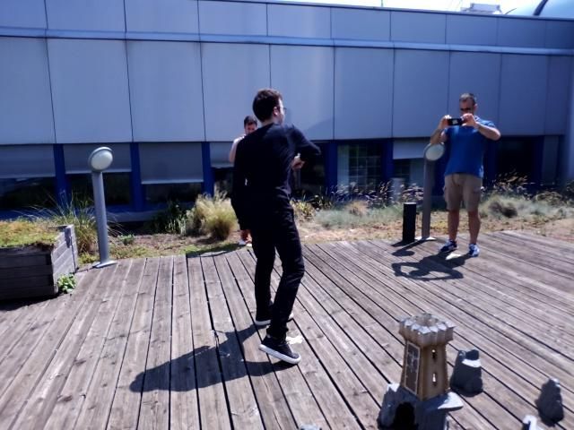
10                                                                                                     Matteo Bortolon et al.

bundle adjustment on 3D points
                                                        mobile 1              mobile 2               mobile 3

                                                        mobile 4              mobile 5               mobile 6
bundle adjustment on 3D points and mobile poses         human poses estimated from each camera

Fig. 9 Reconstructed skeleton and mobile poses from 4DM-Hard. (Top-Left) Bundle Adjustment on 3D points only. (Bottom-
Left) Bundle Adjustment on 3D points and mobile poses. (Right) 2D poses estimated on each captured frame: note OpenPose
mistake in mobile 4 due to a distractor.

                                                                4DM-Easy

     (a)                      (b)

Fig. 10 Overlay between the 3D skeleton triangulated with       4DM-Medium
our method (black) and the skeletons obtained with Video-
Pose3D [35] opportunely rescaled (green and light blue). (a)
Six 3D skeletons estimated from each mobile with Video-
Pose3D (green), and (b) the skeleton whose joints are com-
puted as the centres of mass amongst the corresponding joints
inferred from all the mobiles with VideoPose3D (light blue).
The yellow sphere indicates the point used to make the Video-
Pose3D’s output skeleton coincide with that estimated with      4DM-Hard
our system.

                                                                Fig. 11 Examples of volumetric reconstruction obtained
                                                                with a shape-from-silhouette-based approach applied to our
6.7 Volumetric reconstruction                                   dataset 4DM. Silhouettes are automatically extracted using
                                                                PointRend [23]. Although silhouettes are not accurately fol-
                                                                lowing the outline of the actor, these results show that mobile
Fig. 11 shows examples of volumetric reconstructions            poses and frames are captured synchronously. Shape-from-
                                                                silhouette approaches are typically sensitive to noisy camera
extracted from 4DM-Easy, 4DM-Medium and 4DM-
                                                                poses and synchronisation.
Hard. The supplementary video contains the full se-
quences. Although we are using a fully automated vol-
umetric reconstruction baseline, we can observe that we         7 Conclusions
can achieve promising reconstruction results even when
cameras are moving. Note that the quality of the re-            We presented the first mobile-based system designed
constructed mesh is limited by the number of cameras:           for real-time synchronous image captures that is based
in fact, we can distinguish the intersection of the pro-        on commodity hardware. We exploit a Relay Server to
jected cones. This is a known problem of shape-from-            handle synchronisation triggers and a Data Manager
silhouette based approaches. To obtain reconstructions          to retrieve data (frames and mobile poses) efficiently.
with higher geometric details there should be a larger          These two modules can be deployed at the Edge or
number of cameras or more sophisticated approaches,             in the Cloud as it uses conventional wireless connec-
as those proposed in [34, 32], should be used.                  tions. We showed that our system can effectively cap-
Multi-view data capture for dynamic object reconstruction using handheld augmented reality mobiles 11
ture nearly-synchronous frames that can be used to re- 12. Cao, Z., Simon, T., Wei, S.E., Sheikh, Y.: Realtime Multi-
construct the 3D skeleton and the mesh of a moving Person 2D Pose Estimation using Part Affinity Fields. In:
Proc. of IEEE CVPR. Honolulu, US (2017)
person over time. We empirically observed that mobile 13. Cheung, G.: Visual hull construction, alignment and re-
poses are sometimes inaccurate and that data may un- finement for human kinematic modeling, motion tracking
dergo variable delays. A limitation of our system is that and rendering. PhD thesis, Carnegie Mellon University
non-expert users may capture a dynamic object from in- (2003)
14. Collet, A., Chuang, M., Sweeney, P., Gillett, D., Evseev,
effective viewpoints, for example ending up with small D., Calabrese, D., Hoppe, H., Kirk, A., Sullivan, S.: High-
baselines due to mobiles moving close to each other. quality streamable free-viewpoint video. ACM Trans. on
An improvement could be the implementation of a AR- Graphics 34(4), 1–13 (2015)
based UI/UX to guide non-experts during data cap- 15. Garg, A., Yadav, A., Sikora, A., Sairam, A.: Wireless
Precision Time Protocol. IEEE Communication Letters
tures. Our delay compensation strategy currently com- 22(4), 812–815 (2018)
putes the average RTT over all the past measurements 16. Guillemaut, J.Y., Hilton, A.: Joint Multi-Layer Segmen-
and does not yet take into consideration RTT varia- tation and Reconstruction for Free-Viewpoint Video Ap-
tions that may occur during a capture session. A future plications. International Journal on Computer Vision
93(1), 73–100 (2011)
improvement of this can be the extension of the de- 17. Hartley, R., Zisserman, A.: Multiple View Geometry in
lay compensation strategy by continuously monitoring Computer Vision. Cambridge University Press (2003)
the RTT between host and clients, and updating the 18. He, K., Gkioxari, G., Dollar, P., Girshick, R.: Mask R-
average RTT during capture using past measurements CNN. In: Proc. of IEEE ICCV. Venice, IT (2017)
19. Hu, Y., Niu, D., Li, Z.: A Geometric Approach to Server
within a temporal window. Other future improvements Selection for Interactive Video Streaming. IEEE Trans.
include on-line camera recalibration, on-line latency es- on Multimedia 18(5), 840–851 (2016)
timation to achieve a more robust 3D reconstruction, 20. Huang, C.H., Boyer, E., Navab, N., Ilic, S.: Human shape
and pose tracking using keyframes. In: Proc. of IEEE
and validation on a 5G network infrastructure.
CVPR. Columbus, US (2014)
21. Ionescu, C., Papava, D., Olaru, V., Sminchisescu, C.: Hu-
Acknowledgements This research has received funding man3.6M: Large Scale Datasets and Predictive Methods
from the Fondazione CARITRO - Ricerca e Sviluppo pro- for 3D Human Sensing in Natural Environments. IEEE
gramme 2018-2020. Trans. on PAMI 36(7) (2014)
22. Kim, H., Guillemaut, J.Y., Takai, T., Sarim, M., Hilton,
A.: Outdoor Dynamic 3D Scene Reconstruction. IEEE
Trans. on Circuits and Systems for Video Technology
References 22(11), 1611–1622 (2012)
23. Kirillov, A., Wu, Y., He, K., Girshick, R.: PointRend:
1. ARCore. https://developers.google.com/ar (Ac- Image Segmentation as Rendering. In: Proc. of IEEE
cessed: Mar 2020) CVPR. Seattle, US (2020)
2. Amazon Textract. https://aws.amazon.com/textract/ 24. Latimer, R., Holloway, J., Veeraraghavan, A., Sabharwal,
(Accessed: Oct 2020) A.: SocialSync: Sub-Fr[9]e Synchronization in a Smart-
phone Camera Network. In: Proc. of ECCV Workshops.
3. Amazon Web Services. https://aws.amazon.com (Ac-
Zurich, CH (2015)
cessed: Oct 2020)
25. Laurentini, A.: The visual hull concept for silhouette-
4. Cloud Anchors. https://developers.google.com/
based image understanding. IEEE Trans. on PAMI 16
ar/develop/java/cloud-anchors/overview-android#
(1994)
how-hosted (Accessed: Oct 2020)
26. Leo, M., Mosca, N., Spagnolo, P., Mazzeo, P., D’Orazio,
5. MLAPI Relay. https://github.com/MidLevel/MLAPI. T., Distante, .A.: Real-time multiview analysis of soccer
Relay (Accessed: Oct 2020) matches for understanding interactions between ball and
6. Protocol Buffers. https://developers.google.com/ players. In: Proc. of Content-based Image and Video
protocol-buffers/ (Accessed: Oct 2020) Retrieval. Niagara Falls, CA (2008)
7. Unity3D. https://unity.com/ (Accessed: Oct 2020) 27. Lorensen, W., Cline, H.: Marching Cubes: A High Reso-
8. Unity3D MatchMaking. https://docs.unity3d.com/ lution 3D Surface Construction Algorithm. In: Proc. of
520/Documentation/Manual/UNetMatchMaker.html (Ac- ACM SIGGRAPH. Anaheim, US (1987)
cessed: Oct 2020) 28. Lourakis, M.A., Argyros, A.: SBA: A Software Package
9. Ansari, S., Wadhwa, N., R, G., Chen, J.: Wireless Soft- for Generic Sparse Bundle Adjustment. ACM Trans.
ware Synchronization of Multiple Distributed Cameras. Math. Software 36(1), 1–30 (2009)
In: Proc. of IEEE ICCP. Tokyo, JP (2019) 29. Mikhnevich, M., Hebert, P., Laurendeau, D.: Unsuper-
10. Ballan, L., Brostow, G., Puwein, J., Pollefeys, M.: Un- vised visual hull extraction in space, time and light do-
structured video-based rendering: Interactive exploration mains. Computer Vision and Image Understanding 125,
of casually captured videos. In: Proc. of SIGGRAPH. Los 55–71 (2014)
Angeles, US (2010) 30. Mills, D.: Internet time synchronization: the network
11. Bortolon, M., Chippendale, P., Messelodi, S., Poiesi, F.: time protocol. IEEE Trans. on Communications 39(10)
Multi-view data capture using edge-synchronised mo- (1991)
biles. In: Proc. of Computer Vision, Imaging and Com- 31. Mustafa, A., Hilton, A.: Semantically coherent co-
puter Graphics Theory and Applications. Valletta, MT segmentation and reconstruction of dynamic scenes. In:
(2020) Proc. of IEEE CVPR. Honolulu, US (2017)12 Matteo Bortolon et al.
32. Mustafa, A., Russell, C., Hilton, A.: U4D: Unsupervised
4D Dynamic Scene Understanding. In: Proc. of IEEE
ICCV. Seoul, KR (2019)
33. Mustafa, A., Volino, M., Kim, H., Guillemaut, J.Y.,
Hilton, A.: Temporally coherent general dynamic scene
reconstruction. International Journal in Computer Vi-
sion (2019)
34. Pages, R., Amplianitis, K., Monaghan, D., andA. Smolic,
J.O.: Affordable content creation for free-viewpoint video
and VR/AR applications. Journal of Vis. Comm. and Im.
Repr. 53 (2018)
35. Pavllo, D., Feichtenhofer, C., Grangier, D., Auli, M.: 3D
human pose estimation in video with temporal convolu-
tions and semi-supervised training. In: Proc. of IEEE
CVPR. Long Beach, US (2019)
36. Poiesi, F., Locher, A., Chippendale, P., Nocerino, E., Re-
mondino, F., Gool, L.V.: Cloud-based Collaborative 3D
Reconstruction Using Smartphones. In: Proc. of Euro-
pean Conference on Visual Media Production (2017)
37. Pretto, N., Poiesi, F.: Towards gesture-based multi-user
interactions in collaborative virtual environments. In:
Int. Arch. Photogramm. Remote Sens. Spatial Inf. Sci.,
XLII-2/W8. Hamburg, GE (2017)
38. Qiao, X., Ren, P., Dustdar, S., Liu, L., Ma, H., Chen,
J.: Web AR: A Promising Future for Mobile Augmented
Reality–State of the Art, Challenges, and Insights. Proc.
of the IEEE 107(4), 651–666 (2019)
39. Rematas, K., Kemelmacher-Shlizerman, I., Curless, B.,
Seitz, S.: Soccer on your tabletop. In: Proc. of IEEE Com-
puter Vision and Pattern Recognition. Salt Lake City, US
(2018)
40. Richardt, C., Kim, H., Valgaerts, L., Theobalt, C.: Dense
wide-baseline scene flow from two handheld video cam-
eras. In: Proc. of 3DV. San Francisco, US (2016)
41. Sigal, L., Balan, A., Black, M.: Humaneva: Synchronized
video and motion capture dataset and baseline algorithm
for evaluation of articulated human motion. International
Journal of Computer Vision 87(4) (2009)
42. Slabaugh, G., Schafer, R., Malzbender, T., Culbertson,
B.: A survey of methods for volumetric scene recon-
struction from photographs. In: Proc. of Eurographics.
Manchester, UK (2001)
43. Snavely, N., Seitz, S., Szeliski, R.: Modeling the World
from Internet Photo Collections. International Journal
of Computer Vision 80(2), 189–210 (2007)
44. Soret, B., Mogensen, P., Pedersen, K., Aguayo-Torres,
M.: Fundamental tradeoffs among reliability, latency and
throughput in cellular networks. In: IEEE Globecom
Workshops. Austin, US (2014)
45. Vo, M., Narasimhan, S., Sheikh, Y.: Spatiotemporal Bun-
dle Adjustment for Dynamic 3D Reconstruction. In:
Proc. of IEEE CVPR. Las Vegas, US (2016)
46. Wang, Y., Wang, J., Chang, S.F.: CamSwarm: Instanta-
neous Smartphone Camera Arrays for Collaborative Pho-
tography. arXiv:1507.01148 (2015)
47. Wu, Y., Kirillov, A., Massa, F., Lo, W.Y., Girshick, R.:
Detectron2. https://github.com/facebookresearch/
detectron2 (2019)
48. Yahyavi, A., Kemme, B.: Peer-to-peer architectures for
massively multiplayer online games: A survey. ACM
Comput. Surv. 46(1), 1–51 (2013)
49. Yin, G., Otis, M.D., Fortin, P., Cooperstock, J.: Evaluat-
ing multimodal feedback for assembly tasks in a virtual
environment. In: Proc. ACM Hum.-Comput. Interact.
Glasgow, UK (2019)
50. Zou, D., Tan, P.: COSLAM: Collaborative visual slam in
dynamic environments. IEEE Trans. on Pattern Analysis
and Machine Intelligence 35(2), 354–366 (2013)You can also read