NAVAL POSTGRADUATE SCHOOL - THESIS MONTEREY, CALIFORNIA SECURE REMOTE NETWORK ADMINISTRATION AND - Dtic
←
→
Page content transcription
If your browser does not render page correctly, please read the page content below
NAVAL
          POSTGRADUATE
             SCHOOL
            MONTEREY, CALIFORNIA

                     THESIS
SECURE REMOTE NETWORK ADMINISTRATION AND
           POWER MANAGEMENT

                            by

                     Mark P. Sullivan

                        June 2004

Thesis Advisor:                              Dale Courtney
Second Reader:                               Dennis Volpano

   Approved for public release; distribution is unlimited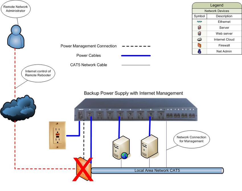
THIS PAGE INTENTIONALLY LEFT BLANK
REPORT DOCUMENTATION PAGE                                            Form Approved OMB No. 0704-0188
 Public reporting burden for this collection of information is estimated to average 1 hour per response, including
 the time for reviewing instruction, searching existing data sources, gathering and maintaining the data needed, and
 completing and reviewing the collection of information. Send comments regarding this burden estimate or any
 other aspect of this collection of information, including suggestions for reducing this burden, to Washington
 headquarters Services, Directorate for Information Operations and Reports, 1215 Jefferson Davis Highway, Suite
 1204, Arlington, VA 22202-4302, and to the Office of Management and Budget, Paperwork Reduction Project
 (0704-0188) Washington DC 20503.
 1. AGENCY USE ONLY (Leave blank)  2. REPORT DATE         3. REPORT TYPE AND DATES COVERED
                                       June 2004                         Master’s Thesis
 4. TITLE AND SUBTITLE: Secure Remote Network Administration and Power 5. FUNDING NUMBERS
 Management
 6. AUTHOR(S) Mark P. Sullivan
 7. PERFORMING ORGANIZATION NAME(S) AND ADDRESS(ES)                    8. PERFORMING
      Naval Postgraduate School                                        ORGANIZATION REPORT
      Monterey, CA 93943-5000                                          NUMBER
 9. SPONSORING /MONITORING AGENCY NAME(S) AND ADDRESS(ES)              10. SPONSORING/MONITORING
      N/A                                                                 AGENCY REPORT NUMBER

 11. SUPPLEMENTARY NOTES The views expressed in this thesis are those of the author and do not reflect the official
 policy or position of the Department of Defense or the U.S. Government.
 12a. DISTRIBUTION / AVAILABILITY STATEMENT                                       12b. DISTRIBUTION CODE
 Approved for public release; distribution is unlimited
 13. ABSTRACT (maximum 200 words)
            Remote Network Administration allows network administrators to manage their networks while being physically
 separated from the network equipment. Having the capability to manage wired and wireless networks securely, from remote
 locations, can substantially reduce operating expenses across the entire Department of Defense

          A variety of methods for remotely managing networks is explored for both wired and wireless networks.
 Requirements for remote network administration are identified. Chief among them is security and the ability to remotely
 manage power. Several widely-used remote management utilities are examined. All fail to meet these two requirements. A
 new power control device is presented that can be managed securely and remotely.

 14. SUBJECT TERMS                                                                                      15. NUMBER OF
 Remote Network Administration, Network Management, Power Management                                    PAGES
                                                                                                                71
                                                                                                        16. PRICE CODE
 17. SECURITY                       18. SECURITY                            19. SECURITY              20. LIMITATION
 CLASSIFICATION OF                  CLASSIFICATION OF THIS                  CLASSIFICATION OF         OF ABSTRACT
 REPORT                             PAGE                                    ABSTRACT
         Unclassified                        Unclassified                         Unclassified                 UL
NSN 7540-01-280-5500                                                                           Standard Form 298 (Rev. 2-89)
                                                                                                  Prescribed by ANSI Std. 239-18

                                                              i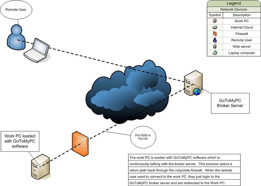
THIS PAGE INTENTIONALLY LEFT BLANK

                ii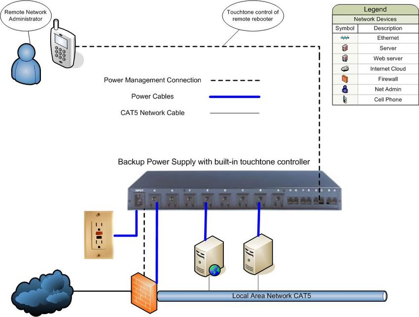
Approved for public release; distribution is unlimited

SECURE REMOTE NETWORK ADMINISTRATION AND POWER
                 MANAGEMENT

                             Mark P. Sullivan
                     Captain, United States Air Force
          B.S., University of Maryland University College, 2000

                   Submitted in partial fulfillment of the
                      requirements for the degree of

          MASTER OF SCIENCE IN COMPUTER SCIENCE

                                  from the

                 NAVAL POSTGRADUATE SCHOOL
                           June 2004

Author:               Mark P. Sullivan

Approved by:          Dale Courtney
                      Thesis Advisor

                      Dennis Volpano
                      Second Reader

                      Peter Denning
                      Chairman, Department of Computer Sciences

                                     iii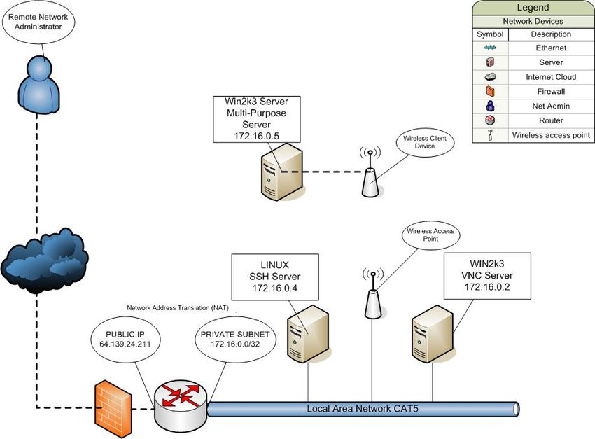
THIS PAGE INTENTIONALLY LEFT BLANK

                iv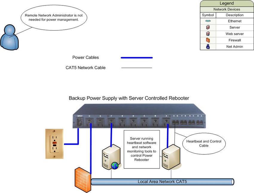
ABSTRACT

       Remote Network Administration allows network administrators to manage their
networks while being physically separated from the network equipment. Having the
capability to manage wired and wireless networks securely, from remote locations, can
substantially reduce operating expenses across the entire Department of Defense

       A variety of methods for remotely managing networks is explored for both wired
and wireless networks. Requirements for remote network administration are identified.
Chief among them is security and the ability to remotely manage power. Several widely-
used remote management utilities are examined. All fail to meet these two requirements.
A new power control device is presented that can be managed securely and remotely.

                                           v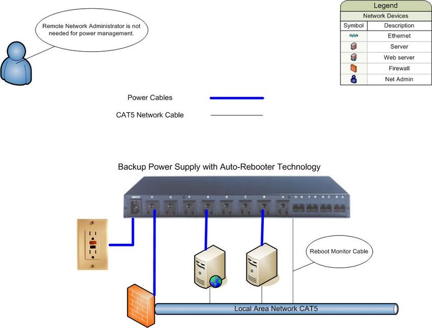
THIS PAGE INTENTIONALLY LEFT BLANK

                vi
TABLE OF CONTENTS

I.     INTRODUCTION........................................................................................................1
       A.   OVERVIEW.....................................................................................................1
       B.   PROBLEM DEFINITION ..............................................................................1
       C.   MOTIVATION ................................................................................................1
       D.   OBJECTIVE ....................................................................................................1
       E.   SCOPE ..............................................................................................................2
       F.   THESIS ORGANIZATION............................................................................2
II.    ELEMENTS OF WIRED AND WIRELESS NETWORKS....................................3
       A.  INTRODUCTION............................................................................................3
       B.  WIRED NETWORK ELEMENTS ................................................................3
           1.   Topology................................................................................................3
           2.   Capabilities ...........................................................................................4
           3.   Star ........................................................................................................4
           4.   Bus .........................................................................................................5
           5.   Ring .......................................................................................................6
           6.   Mesh ......................................................................................................6
       C.  WIRELESS NETWORK ELEMENTS .........................................................7
           1.   Capabilities ...........................................................................................7
           2.   Topology................................................................................................8
           3.   Equipment ..........................................................................................10
       D.  CONCLUSION ..............................................................................................10
III.   WIRELESS VS. WIRED NETWORK MANAGEMENT .....................................13
       A.  INTRODUCTION..........................................................................................13
       B.  WIRED NETWORK MANAGEMENT UTILITIES/DEVICES..............13
           1.    Telnet...................................................................................................13
           2.    Secure Shell (SSH) .............................................................................14
           3.    Simple Network Management Protocol (SNMP) ............................15
           4.    Remote Desktop .................................................................................15
                 a.     Windows ..................................................................................16
                 b.     Virtual Network Computing (VNC) .......................................16
                 c.     Citrix ........................................................................................17
                 d.     Virtual Private Network (VPN) ..............................................18
                 e.     Point-to-Point Tunneling Protocol (PPTP) ...........................18
                 f.     Layer 2 Tunneling Protocol (L2TP).......................................18
                 g.     Internet Protocol Security (IPSEC) .......................................18
       C.  WIRELESS NETWORK MANAGEMENT UTILITIES/DEVICES.......19
       D.  CONCLUSION ..............................................................................................21
IV.    REMOTE NETWORK MANAGEMENT AND ITS SECURITY RISKS ..........23
       A.  INTRODUCTION..........................................................................................23
       B.  WIRED NETWORK REMOTE MANAGEMENT UTILITIES..............24
           1.   Telnet...................................................................................................24
                                             vii
2.  SSH ......................................................................................................25
                    3.  SNMP ..................................................................................................26
                    4.  Remote Desktop Utilities ...................................................................26
                        a.      Windows Remote Desktop Protocol........................................26
                        b.      Virtual Network Computing (VNC) .......................................27
                        c.      Citrix ........................................................................................30
                        d.      GoToMyPC..............................................................................31
                    5.  VPN .....................................................................................................33
                        a.      Point-to-Point Tunneling Protocol (PPTP) ...........................33
                        b.      Layer 2 Tunneling Protocol....................................................33
                        c.      Internet Protocol Security.......................................................33
                        d.      L2TP + IPSec ..........................................................................34
                        e.      Tunneling ................................................................................34
         C.         WIRELESS NETWORK REMOTE MANAGEMENT UTILITIES.......35
         D.         CONCLUSION ..............................................................................................39
V.       DEVICES LACKING NETWORK MANAGEMENT (OR THE WEAK
         LINK) ..........................................................................................................................41
         A.    INTRODUCTION..........................................................................................41
         B.    TAKING CONTROL OF YOUR POWER.................................................41
         C.    BACKUP METHODS OF REMOTE POWER REBOOTING ................43
         D.    CONCLUSION ..............................................................................................49
VI.      CONCLUSION ..........................................................................................................51
         A.  RESEARCH CONCLUSION .......................................................................51
         B.  RECOMMENDATIONS FOR FURTHER RESEARCH .........................52
LIST OF REFERENCES ......................................................................................................53
INITIAL DISTRIBUTION LIST .........................................................................................55

                                                              viii
LIST OF FIGURES
Figure 2.1. Star Topology (From:
http://www.delmar.edu/Courses/ITNW2313/network.htm, May 2004)............4
Figure 2.2. Bus Topology (From:
http://www.delmar.edu/Courses/ITNW2313/network.htm, May 2004)............5
Figure 2.3. Ring Topology (From:
http://www.delmar.edu/Courses/ITNW2313/network.htm, May 2004)............6
Figure 2.4. Mesh Topology (From:
http://www.delmar.edu/Courses/ITNW2313/network.htm, May 2004)............7
Figure 2.5. Ad hoc (peer to peer) vs. Infrastructure (base station) (From: Gast. 802.11
Wireless Networks – The Definitive Guide. (O’Reilly, 2002), 11) ....................8
Figure 2.6. Ad hoc Wireless Network (From:
http://www.informit.com/articles/article.asp?p=101591, May 2004) ...............9
Figure 2.7. Typical Hybrid Network Diagram Showing Wireless and Wired Access
(From: Gast. 802.11 Wireless Networks – The Definitive Guide.
O’Reilly, 2002, 11) ..........................................................................................10
Figure 3.1. Telnet Login from Command Prompt .............................................................13
Figure 3.2. PuTTY SSH Client ..........................................................................................14
Figure 3.3. SSH Login on Router-Based SSH Server........................................................15
Figure 3.4. Router System Log Showing Login Process ...................................................15
Figure 3.5. VNC Login Prompts ........................................................................................16
Figure 3.6. Remote VNC Desktop on Top of Local Desktop ............................................17
Figure 3.7. Web-Based Management Tool for Linksys WAP (From:
www.linksys.com, May 2004) .........................................................................20
Figure 3.8. SNMP Client Software ....................................................................................21
Figure 4.1. Test-Bed Network developed for thesis testing ...............................................23
Figure 4.2. Telnet Login Password (Cisco) Shown in cleartext (From:
www.ethereal.com, May 2004)........................................................................24
Figure 4.3. Initial SSH Connection Shows Server Fingerprint ..........................................25
Figure 4.4. VNC Server Configuration ..............................................................................27
Figure 4.5. PuTTY Connections.........................................................................................28
Figure 4.6. PuTTY SSH Version and Compression...........................................................28
Figure 4.7. PuTTY Tunnel Configuration..........................................................................29
Figure 4.8. PuTTY Session Configuration.........................................................................30
Figure 4.9. VNC Remote Login through SSH Tunnel .......................................................30
Figure 4.10. Citrix ICA 128-bit Encryption Configuration..................................................31
Figure 4.11. GoToMyPC circumvents firewall policies ......................................................32
Figure 4.12. Wireless Access Points in DMZ (From: Osbourne. CWNA, Certified
Wireless Network Administrator. McGraw Hill, 2003, 418) .........................36
Figure 4.13. Common Wired Backbone (From: Osbourne. CWNA, Certified Wireless
Network Administrator. McGraw Hill, 2003, 101) ........................................36
ixFigure 4.14. Wireless Bridge (From: Osbourne. CWNA, Certified Wireless Network
Administrator. McGraw Hill, 2003, 102) .......................................................37
Figure 5.1. Web-Based Interface Rebooter (From: http://www.wti.com, May 2004) .......42
Figure 5.2. Remotely Manageable UPS is Unreachable Due to Key Router Being
Down................................................................................................................43
Figure 5.3. Command Line Interface for Remote Rebooter (From:
http://www.wti.com, May 2004)......................................................................44
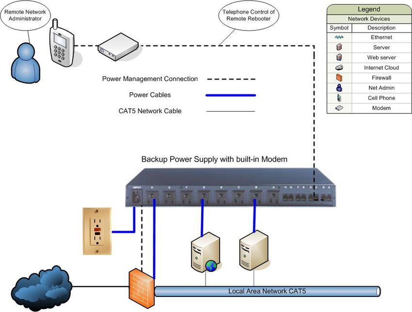
Figure 5.4. UPS with Built-In Modem for Remote Management ......................................45
Figure 5.5. UPS with Remote Management via Built-in Touchtone Controller................46
Figure 5.6. Backup Power Supply Controlled by Server Loaded with Heartbeat
Software ...........................................................................................................47
Figure 5.7. Backup Power Supply with Built-in Auto-Rebooter .......................................48
Figure 5.8. Backup Power Supply with Built-In Auto-Rebooter and Backup
Management.....................................................................................................49
xLIST OF ABBREVIATIONS, ACRONYMS AND SYMBOLS
APC American Power Conversion
ATM Asynchronous Transfer Mode
AH Authentication Header
ESP Encapsulating Security Payload
EAP-TLS Extensible Authentication Protocol - Transport Layer Security
ICMP Internet Control Message Protocol
IETF Internet Engineering Task Force
IKE Internet Key Exchange
IP Internet Protocol
IPSEC Internet Protocol Security
L2F Cisco's Layer 2 Forwarding
L2TP Layer 2 Tunneling Protocol
LAN Local Area Network
NAT Network Address Translation
PPP Point-to-Point Protocol
PPTP Point-to-Point Tunneling Protocol
RDP Remote Desktop Protocol
SSH Secure Shell
SSL Secure Socket Layer
SNMP Simple Network Management Protocol
TCP Transmission Control Protocol
UPS Uninterruptible Power Supply
UDP User Datagram Protocol
VLAN Virtual Local Area Network
VNC Virtual Network Computing
VPN Virtual Private Network
WEP Wired Equivalent Privacy
WAP Wireless Access Point
xiTHIS PAGE INTENTIONALLY LEFT BLANK
xiiACKNOWLEDGMENTS
I would like to thank my advisors, the NPS Staff, AFIT Staff, and my fellow
students for the opportunity to learn.
xiiiTHIS PAGE INTENTIONALLY LEFT BLANK
xivI. INTRODUCTION
A. OVERVIEW
This thesis explores the many methods of remote network administration for both
wired and wireless networks. This project is undertaken in an effort to provide the
Department of Defense several solutions for secure remote network administration.
Specifically, this thesis researches the necessary components that enable complete and
secure network administration from a remote location.
B. PROBLEM DEFINITION
Performing network administration remotely, from a central location, is possible.
However, for each service opened in a firewall, there is another potential vulnerability,
which may be exploitable by hackers. To perform remote network administration
securely is the true problem researched in this thesis.
C. MOTIVATION
The Department of Defense is continually pushed to do more with less. In this
effort, more and more locations are becoming administered from central locations,
normally within the same geographic area. To reduce the required manpower further, it
is necessary to push the management even further away, sometimes leaving an area
completely unmanned.
In order to enable centralized management, from geographically separated
locations, remote management tools must be implemented. These tools must be all
encompassing, flexible, and most importantly, secure.
D. OBJECTIVE
In support of the Department of Defense's objectives, this thesis surveys several
methods for secure remote network administration. Remote network administration
greatly reduces the manning required for the day-to-day maintenance of our networks.
This thesis also investigates any possible weak-links with remote administration and
attempts to identify automated processes to deal with them. Lastly, this thesis will
attempt to build a test bed to incorporate the recommended utilities and/or hardware.
1E. SCOPE
This thesis will research, and test when possible, open-source, freeware, and
widely available remote network management utilities. The focus being on cost savings,
this thesis will test commercial off the shelf software that is already incorporated into
widely used operating systems throughout the Department of Defense, such as Windows
XP Professional and Windows Server 2003.
F. THESIS ORGANIZATION
This thesis is organized into six chapters. Chapter II discusses background
information pertaining to wired and wireless networks. Specifically, it discusses the
topology, equipment, and capabilities of each. Chapter III discusses wired and wireless
network management tools. Chapter IV discusses how to effectively, and securely, use
the tools outlined in Chapter III. Chapter V discusses those devices, which support
networks, but are not normally network manageable. Specifically, it discusses remote
power management and an automated method of reducing downtime. Chapter VI is the
conclusion. It discusses the results of the test bed and recommends topics for future
research.
2II. ELEMENTS OF WIRED AND WIRELESS NETWORKS
A. INTRODUCTION
In order for computers to communicate with one another and share resources, they
must somehow connect to each other, either in the form of a wired or wireless
connection. Regardless of the connection, a typical network has several key components
including networking cards, cabling, routers, and switches, as well as bridges, gateways,
firewalls, servers, and backup power supplies. These devices not only comprise a
network, but also establish communication between all devices including client
workstations and shared resources such as printers and scanners.
B. WIRED NETWORK ELEMENTS
1. Topology
Network topology refers to the arrangement or physical layout of computers,
cables, and other components on the network. Topology is a commonly used term by
network professionals when referring to the network’s basic design. Topologies can be
physical (cabling) or logical (how they work). Topology is synonymous with words such
as physical layout, design, diagram, and map.1
Topology is a key factor when determining network capabilities. Each different
topology has its own capabilities and affects the equipment needed, future growth
potential of a network, and most importantly, the management of the network.
Primary topologies include star, bus, ring, and mesh. A star topology forms when
computers connect to wired segments, which branch out from a single point. A bus
topology forms when each connected device shares a common wire (cable). A ring
topology is computers connected to a wire that forms a loop. All devices connecting
directly to all other devices form a mesh topology. Furthermore, two or more of the
above standard topologies used together can comprise a hybrid method for networking as
well.2
1 Tamar Dean, Enhanced Network+ Guide to Networks. Enhanced Edition, (Course Technology,
2003), 178.
2 Forouzan, Data Communications and Networking. 2nd Edition, (McGraw Hill, 2001), 22.
32. Capabilities
The selection of hardware and cabling will affect the overall network performance
for each of the network topologies. For example, fiber has a higher throughput than
coaxial cable. Other factors affecting network performance are the types of operating
systems, client/server applications, and distances between devices.
3. Star
Since all network communications must flow through a central connection device,
centralized management is an obvious advantage to the star topology. It is also a possible
weakness since a single-point-of-failure now exists. Depending on the physical locations
of all network devices, the star topology may demand a higher amount of cabling to allow
all devices to connect back to the central device. However, since all devices possess
individual connections back to the central device, a single computer failure will not affect
the rest of the network.3
Figure 2.1. Star Topology (From:
http://www.delmar.edu/Courses/ITNW2313/network.htm, May 2004)
3 Feibel, Encyclopedia of Networking. Network Press. (Sybex, 2000), 1166
44. Bus
Only one computer can transmit at a time on a bus network. Therefore, the
number of computers attached to a single bus will affect the overall network
performance. In a bus network, each computer is not responsible for passing data from
one computer to the next. As with star topology, the failure of one computer will not
affect the other devices connected to the same bus. Data passes from one device to the
next by transmitting the data onto the bus with an address for the specific recipient. The
use of a “terminator” stops the signal bounce, or otherwise, this data will continue to
bounce from one end of the bus to the other. A terminator may be a hardware device, or
even another computer, which is designed to absorb the signal thereby preventing bounce
back. In any case, the bus must not have unterminated ends, which would cause bounce
back of the signal, disallowing any further data to enter the bus. If a break in the bus
occurs at any point, an unterminated endpoint will result, and therefore, all network
communication will stop due to bounce back. Each computer will still function but will
not have network communication capability.4
Network growth is possible by either installing a completely new bus line or by
extending the current bus. The use of a connector can cause an extension (i.e. barrel
connector). Connectors introduce resistance and therefore weaken the signal. Using
excessive connectors without the use of a repeater can affect network performance
detrimentally. A repeater is essentially an amplifier used in series to boost the signal.
Figure 2.2. Bus Topology (From:
http://www.delmar.edu/Courses/ITNW2313/network.htm, May 2004)
4 Tanenbaum. Computer Networks. (Prentice Hall, 2003), 17
55. Ring
A ring topology is often confused with a bus topology when the bus connects at
both ends. However, a ring topology is different from a bus topology. The data passes
along the ring in one direction and passes through each computer in a ring topology. Each
computer receives the signal, determines if the data is destined for itself or not, and if not,
will retransmit the signal out to the next computer in the ring. Therefore, the failure of a
single computer will impact the entire network.5
Figure 2.3. Ring Topology (From:
http://www.delmar.edu/Courses/ITNW2313/network.htm, May 2004)
6. Mesh
A mesh topology is superior to the bus, ring, and star. Since each computer
connects to every other computer in the network directly, a greater level of redundancy
and reliability exists. If one connection fails between computer A and computer B, many
redundant paths are still available for communication to continue between computer A
and computer B. Cost is the main disadvantage to a mesh topology. Connecting every
device to one another requires a great deal of cabling. The cost of this cabling makes the
mesh network prohibitive to a majority of network planners.6
5 Feibel, Encyclopedia of Networking. Network Press, (Sybex, 2000), 1165.
6 Tamar Dean. Enhanced Network+ Guide to Networks, Enhanced Edition. (Course Technology,
2003), 191.
6Figure 2.4. Mesh Topology (From:
http://www.delmar.edu/Courses/ITNW2313/network.htm, May 2004)
C. WIRELESS NETWORK ELEMENTS
The initial planning for the deployment of a wireless network is more difficult
than planning a wired network deployment. A wired network only requires cables be run
to the associated network device for backbone connectivity. The deployment of wireless
networks requires many more factors to consider over traditional wired networks.
Besides the RF issues inherent to wireless networks, it is also necessary to
consider the interfaced wired network. In most cases, the wireless network will extend
the reach of a wired network. Therefore, the stability of the wired network is crucial to
wireless network stability as well.7 Although the initial planning may be more difficult
and time consuming, it does result in decreased overall time and costs to provide network
connectivity to expanded customers and devices.
1. Capabilities
Wireless networks allow clients and network devices to connect to the network
without a hardwire cable, either for ease or necessity. When initially deploying a
network with a non-existent hardwire backbone, it is possible to establish a wireless
network in a short time allowing immediate network connectivity for users and associated
network devices. It would be a perfect application for a military field deployment if a
hardwire Ethernet backbone does not already exist. Wireless networking would also
allow for a mobile deployment, as it will not be necessary to roll out or roll in cabling.
7 Gast. 802.11 Wireless Networks – The Definitive Guide. (O’Reilly, 2002), 293.
7Wireless networks have two different modes: infrastructure and ad hoc. The ad
hoc network provides connectivity directly between network devices without the need for
a common access point. The infrastructure mode is the most common wireless network
in use, which uses an access point for relaying information to and from wireless clients.
Figure 2.5. Ad hoc (peer to peer) vs. Infrastructure (base station) (From: Gast. 802.11
Wireless Networks – The Definitive Guide. (O’Reilly, 2002), 11)
Wireless networks allow for expansion to a pre-existing wired network. This
reduces cost by eliminating expensive cabling and greatly reducing the time needed for
providing network connectivity to expanded users and devices.
Allowing roaming between access points depends on the wireless network's
purpose. This would be especially beneficial within buildings, but not necessarily
between buildings as this may pose a security risk. Roaming would allow a client device
(i.e. laptop) to stay connected while moving from, for example, an office to the
conference room, without having to reestablish the network connection.
2. Topology
Wireless network topologies refer to the manner in which the wireless devices
communicate with each other and other network devices. Ad hoc networks are normally
established for a specific purpose (i.e. collaborating) and for a short period.8 (See Figure
2.6.)
8 Gast. 802.11 Wireless Networks – The Definitive Guide. (O’Reilly, 2002), 11.
8Figure 2.6. Ad hoc Wireless Network (From:
http://www.informit.com/articles/article.asp?p=101591, May 2004)
Figure 2.7 shows a typical wireless network interfacing with a corporate LAN. It
is important to note that the physical connection of each Access Point is not necessarily
on a separate wired backbone. The wired backbone may be the same backbone servicing
the entire internal network, but possibly separated virtually for security purposes by
statically assigning the Access Points IPs in a subnet separate from the wired internal
LAN. Separating the access points from internal LAN devices allows the implementation
of more stringent security rules for wireless access clients.
9Figure 2.7. Typical Hybrid Network Diagram Showing Wireless and Wired Access
(From: Gast. 802.11 Wireless Networks – The Definitive Guide. O’Reilly, 2002, 11)
3. Equipment
Ad hoc wireless networks require a wireless NIC at each client device, in the form
of a PCMCIA card, internal wireless NIC, or external wireless NIC. Infrastructure
wireless networks need at least one access point in addition to wireless NICs at each
client device. In most cases, a wireless network will interface with a pre-existing wired
LAN. Building a network from scratch also requires all the aforementioned equipment
for wired networks.
D. CONCLUSION
Functional requirements, the size of the network, standards, and funds available
are some of the factors to consider when deciding on a network topology. Network
topology should always be determined early in the design phase. Pros and cons exist for
each topology. However, the ease of adding and removing computers, the centralized
10monitoring and management, and the reduction of network outages due to single device
failure are the reasons that the start topology is the most used.
Wireless technology is improving rapidly and along with that is its popularity.
Many different wireless solutions would be beneficial to the Department of Defense,
ranging from roaming within a warehouse, building-to-building connectivity, and highly
mobile field deployments.9
When deciding between wired and wireless networks, you must take into
consideration start-up costs, functionality, security, and remote management capability.
The next chapter discusses the different management interfaces possible with wired and
wireless networks.
9 Osbourne. CWNA, Certified Wireless Network Administrator. Chapter 1, (McGraw Hill, 2003).
11THIS PAGE INTENTIONALLY LEFT BLANK
12III. WIRELESS VS. WIRED NETWORK MANAGEMENT
A. INTRODUCTION
The first step in network management is to decide on the kind of network—wired,
wireless, or both—and the network topology. The next step is the type of equipment
used to implement the network design. It is important to choose the network devices
carefully in order to have a central management system also capable of remote
management. For cost and simplicity, it would be best to choose the network devices
based on some common management functionality, for example, SSH capability. This
chapter discusses the most common network management utilities.
B. WIRED NETWORK MANAGEMENT UTILITIES/DEVICES
1. Telnet
Telnet is by far the most popular way to configure a network device remotely
since telnet is now included in almost every network device available. It is possible to
initiate a telnet session from almost any command prompt (see Figure 3.1). The remote
administrator can gain access to a command line interface by simply entering a username
and password. From the command line interface, the remote administrator can perform
actions from router configuration to reboot procedures. Most network devices are
accessible and manageable via the telnet interface.10
Figure 3.1. Telnet Login from Command Prompt
10 Forouzan, Data Communications and Networking. 2nd Edition, (McGraw Hill, 2001), 742.
132. Secure Shell (SSH)
SSH is nothing more than secure telnet. SSH uses public key-based
authentication or strong encryption to protect the username and password during the
authentication process. Once authenticated, the remote administrator has the same
capabilities as if using the telnet interface, while the entire process is encrypted. Telnet,
rlogin, and other insecure remote utilities can use SSH as a replacement. To use SSH, the
source must have a SSH client such as freeware PuTTY (see Figure 3.2) and the
destination must have a SSH server. Most Unix/Linux systems have a SSH server built
into the operating system. Windows does not have a built-in SSH server. Therefore, it is
necessary to use a third party SSH server, such as the freeware OpenSSH
(http://sshwindows.sourceforge.net/), or commercial SSH Tectia (http://www.ssh.com).11
Figure 3.2. PuTTY SSH Client
11 Northcutt, Zeltser, Winters, Frederick, and Ritchey. Inside Network Perimeter Security. (New
Riders, 2003), 145.
14Figure 3.3. SSH Login on Router-Based SSH Server
Figure 3.4. Router System Log Showing Login Process
3. Simple Network Management Protocol (SNMP)
SNMP is a tool (protocol) that allows remote and local management of items on
the network including servers, workstations, routers, switches, and other managed
devices. SNMP has been around since 1988 and has evolved through many versions, the
most popular of which are SNMP version 1 and SNMP version 3. Many different
management products use SNMP to manage geographically separated network devices.12
4. Remote Desktop
Remote Desktop utilities allow a user to connect to a remote computer and use
this computer as if sitting in front of it. Remote Desktop utilities make it possible to see
the GUI of the remote PC's operating system through streaming graphics back to the local
PC, presenting the graphics within the remote desktop utility window. In turn, the mouse
clicks/movements and keystrokes are sent to the remote PC. A username and password
authenticate most remote desktop utilities (see Figure 3.5). Several different types of
terminal services, (also known as remote desktop utilities) exist.
12 Ibid., 148 and 474.
15a. Windows
Windows Remote Desktop allows access to a Windows session running on
a computer from a remote location. This provides a connection to a work computer from
home and access to all applications, files, and network resources as if sitting in front of
the work computer. The remote user is actually controlling a specific machine, not a
virtual profile, such as it is with Citrix.
b. Virtual Network Computing (VNC)
VNC is freeware software that makes it possible to view and fully-interact
with one computer from any other remote computer or mobile device. VNC software is
cross-platform capable, which allows remote control between different types of computer
and operating systems. Any desktop can be controlled remotely from within a browser
via the Java viewer without having to install software (see Figure 3.6). VNC includes
both the client-side and server-side software in one package. The network administrator
can choose to enable the server side on any machines configured for remote control.
VNC has a wide range of applications including system administration, IT support, and
helpdesks. The system allows several connections to the same desktop, providing an
invaluable tool for collaborative or shared working in the workplace or classroom.13
Figure 3.5. VNC Login Prompts
13 http://www.realvnc.com (May 2004)
16Figure 3.6. Remote VNC Desktop on Top of Local Desktop
c. Citrix
The Citrix MetaFrame Access Suite is a commercial program allowing
Windows programs to run on another machine as if it were running on a personal
machine. The computer's keyboard, mouse, and monitor are used for interacting with the
program, but the actual processing happens on a remote computer. The user installs a
Citrix client that interacts with the Citrix server. The configuration of a separate server
with the Citrix Server software illustrates the difference between Citrix MetaFrame
Access Suite and VNC or Windows Remote Desktop. When clients log into the Citrix
server, clients will see their network profile desktop, not a specific computer's desktop.14
14 http://www.citrix.com (May 2004).
17Citrix has recently bought out goToMyPC.com, and the combination of
Citrix and GoToMyPC's web-based remote access is now even better. Instead of
installing client software on the local PC, it is now possible to access the remote access
servers via GoToMyPC's website. GoToMyPC Corporate also has complete online
administration for managing an employee’s remote-access privileges.
a. Virtual Private Network (VPN)
VPN provides users a secure link to access a corporate network over the
Internet or other public or private networks without the expense of leased lines. A VPN is
secured by a combination of tunneling, encryption, authentication, access control, and
auditing technologies/services used to transport traffic over the Internet or any insecure
network that uses the TCP/IP protocol suite for communication. The three most popular
VPN technologies are PPTP, IPSec, and L2TP.15
b. Point-to-Point Tunneling Protocol (PPTP)
PPTP is a PPP tunneling protocol designed to allow PPP links to terminate
over a routed network upstream from a NAS. The protocol was defined by the PPTP
forum (a group of computer technology manufacturers including Microsoft, US Robotics,
Ascend, and 3Com). PPTP encapsulates PPP packets within Internet Protocol (IP)
packets using GRE making forwarding over any IP network possible. Unlike IPSec,
PPTP does not specify any security for tunneled traffic. One great advantage of PPTP
over IPSec is that PPTP works through NAT. Another advantage is its integration with
many hardware devices and is widely available in operating systems.
c. Layer 2 Tunneling Protocol (L2TP)
L2TP is also PPP tunneling protocol. RFC 2661 defines L2TP and takes
the best of Cisco's Layer 2 Forwarding (L2F) protocol and PPTP. L2TP can send
encapsulated PPP packets over IP, x.25, frame relay, or ATM networks.
d. Internet Protocol Security (IPSEC)
IPSec runs at the network layer and provides authentication and
encryption as defined by the Internet Engineering Task Force (IETF). By using a
combination of Internet Key Exchange (IKE), Encapsulating Security Payload (ESP), and
Authentication Header (AH), IPSec can protect any protocol that runs on top of IP, such
15 Northcutt, Zeltser, Winters, Frederick, and Ritchey. Inside Network Perimeter Security. (New
Riders, 2003), 186 and 222.
18as TCP, UDP, and ICMP. These services allow for authentication, integrity, access
control, and confidentiality. IPSec allows for encryption and verification of the
information exchanged between remote sites.16
C. WIRELESS NETWORK MANAGEMENT UTILITIES/DEVICES
Without a common wired backbone, managing wireless networks is significantly
harder than managing wired networks for many reasons. One of the main problems is the
unpredictable behavior of wireless channels due to fading, multi-path interference, hidden
nodes, and jamming. Signal quality can vary quite dramatically, which might suddenly
reduce the efficiency of the management operation. The bandwidth of wireless links is
another issue that will always be limited due to the properties of the physical medium and
regulatory limits on the use of radio spectrum. Therefore, it is necessary for network
protocols to utilize the available bandwidth efficiently.
Wireless management interface utilities are improving but still need many
changes and enhancements. Vendors are more concerned with selling low-cost wireless
devices and lightweight operating systems than developing scalable and manageable
enterprise-class devices. Most manufacturers save money by using low-powered
hardware, which does not support the more sophisticated management interfaces. As
such, SNMP-based or web-based management interfaces are what remain. Both methods
have their benefits, but unless coupled with a security feature such as SSL or SNMP-v3,
they are insecure.17
• Web-based management occurs by pointing the web browser at the access
point’s IP address and logging in via a username and password. The web-
based network management utilities are feature-rich and easy to use.
• Telnet is normally accessed via wired access (i.e. serial and Ethernet).
However, telnet can be enabled for wireless access as well. The
implementation of SSH occurs rarely, but is a welcome addition to
securing telnet.
• SNMP, as discussed earlier, is a tool (protocol) that allows for remote and
local management of items on the network including servers,
workstations, routers, switches and other managed devices. Most wireless
devices have a SNMP agent running as a management mechanism and
SNMP client software installed to access their equipment (see Figure 3.8).
16 Kaufman, Perlman, and Speciner. Network Security. (Prentice Hall, 2002), 423.
17 Gast. 802.11 Wireless Networks – The Definitive Guide. (O’Reilly, 2002), 264.
19• Serial management normally connects via a RS232 or USB connection.
Most vendors will use proprietary management software for access that is
capable of only running on one operating system.18
Figure 3.7. Web-Based Management Tool for Linksys WAP (From:
www.linksys.com, May 2004)
18 Ibid.
20Figure 3.8. SNMP Client Software
Most enterprise wireless gateways are VPN enabled. The VPN protocols
supported are most commonly PPTP, IPSec, and L2TP.19
D. CONCLUSION
Many different types of network management utilities exist, and each possesses
advantages and disadvantages. Implementing remote management is simple. Having
secure and easy to use remote management is not. This chapter provided a basic
knowledge of the most common management utilities. The following chapter discusses in
more detail how to implement each method in a secure fashion.
19 Osbourne. CWNA, Certified Wireless Network Administrator. (McGraw Hill, 2003), 406.
21THIS PAGE INTENTIONALLY LEFT BLANK
22IV. REMOTE NETWORK MANAGEMENT AND ITS SECURITY
RISKS
A. INTRODUCTION
The previous chapter discussed many methods for remotely managing networks.
Each of these methods provides a new way for authorized remote administrators to access
a system remotely but also presents a potential way for unauthorized users to gain access.
The more remote utilities in use, the more ports it is necessary to open in the perimeter
firewall, thereby weakening defenses.
This chapter discusses some methods for reducing the risk of using remote
management utilities. It is important to understand that the fewer utilities used the better.
Limiting the amount of remote network utilities not only limits the amount of holes in the
perimeter defenses, but it is easier for the remote network administrator to manage since
fewer utilities exist with which to interface.
Figure 4.1. Test-Bed Network developed for thesis testing
23B. WIRED NETWORK REMOTE MANAGEMENT UTILITIES
Wired network remote management utilities include Telnet, SSH, SNMP, Remote
Desktop Utilities, and Virtual Private Networks (VPN's). Each of these utilities has its
pros and cons based on functionality and security. This section will discuss how to
utilize each of the utilities effectively and securely.
1. Telnet
Telnet passes login name and password in clear text, yet it remains the most
popular method of remotely administering network devices. It is possible to configure
any basic network sniffer, such as Ethereal (www.Ethereal.com), to watch for telnet
traffic on the network. For this reason, capturing and exploiting usernames and
passwords is easy when using telnet. Figure 4.1 shows password “cisco” in clear text.20
Figure 4.2. Telnet Login Password (Cisco) Shown in cleartext (From:
www.ethereal.com, May 2004).
20 Northcutt, Zeltser, Winters, Frederick, and Ritchey. Inside Network Perimeter Security. New
Riders, 2003, 144.
24Using access control lists and limiting the telnet access to only those authorized to
administer the network device can make telnet more secure. Furthermore, the use of
network switches in lieu of hubs will limit the interception location of telnet traffic. For
these reasons, telnet should be disabled and blocked at the perimeter firewall unless it is
the only method of administration.21
2. SSH
SSH is the secure substitute for telnet. SSH uses public key-based authentication
or strong encryption to protect the username and password during the authentication
process. This prevents network sniffers from capturing the login information.22 It is
necessary to always verify the SSH server's fingerprint when establishing the SSH
connection for the first time. (see Figure 4.2).
Figure 4.3. Initial SSH Connection Shows Server Fingerprint
Most manufactures still use cleartext telnet for remote command-line interfaces,
although it is possible to license OpenSSH for incorporation into proprietary products at
no charge (www.openssh.com).
21 Barnes, Bautts, Lloyd, Ouellet, Posluns, Zendzian. Hack Proofing your Wireless Network.
Syngress, 2002,78.
22 Northcutt, Zeltser, Winters, Frederick, and Ritchey. Inside Network Perimeter Security. New
Riders, 2003, 145.
253. SNMP
SNMP is an easy and popular way of managing network devices, especially in
large, complicated networks. However, versions 1 and 2c, like telnet, pass login
information in the form of community strings (also known as passwords) in the clear (see
Figure 4.1). SNMP version 3 supports encryption and cryptographic authentication.
Therefore, if SNMP is required for remote network management, SNMP version 3 is
highly recommended.23 Once again, it is highly recommended to disable SNMP
management and block it at the perimeter firewall unless it is the only method of
management available.
4. Remote Desktop Utilities
Remote Desktop utilities, without the use of encryption, are wide-open to “man-
in-the-middle” attacks. Not only is the login information normally sent in the clear, a
“man-in-the-middle” could easily view the exact desktop at the same instant the remote
administrator is viewing it. The following remote desktop utilities have incorporated, at a
minimum, login encryption.
a. Windows Remote Desktop Protocol
Windows Remote Desktop Protocol (RDP) now incorporates RSA
Security's RC4 cipher for security. Beginning with Windows 2000, administrators can
choose to encrypt data using a 56- or 128-bit key. To prevent unauthorized interception
of the data as it travels between the client and server, enable encryption. This capability
prevents sending login information in the clear, and therefore, is significantly more
secure.
Encryption can be set to one of the following three levels:24
• High: encrypts both the data sent from client to server and the data sent
from server to client using a 128-bit key.
• Medium: encrypts both the data sent from client to server and the data sent
from server to client using a 56-bit key if the client is a Windows 2000 or
above client, or a 40-bit key if the client is an earlier version.
23 Barnes, Bautts, Lloyd, Ouellet, Posluns, Zendzian. Hack Proofing your Wireless Network.
Syngress, 2002, 315.
24 http://www.microsoft.com/windowsxp/remotedesktop/. March, 2003.
26• Low: encrypts only the data sent from client to server, using either a 56 or
40-bit key, depending on the client version. Useful to protect usernames
and passwords sent from client to server.
RDP also incorporates various levels of data compression and caching to
reduce the amount of transmitted data. This greatly enhances the performance over low-
bandwidth connections.
b. Virtual Network Computing (VNC)
Virtual Network Computing (VNC) has little security built-in. It provides
encrypted username password authentication, but no encryption for the data that follows.
Therefore, tunneling VNC over Secure Shell is critical. It is first necessary to setup the
VNC server to listen on an obscure port such as port 6005. The VNC server is defaulted
to listen on port 5900, but default settings are rarely acceptable from a security
standpoint, as discussed later in this chapter. To change the listening port from 5900 to
6005, add 105 in the Display Number block (see Figure 4.4). Then, check the Accept
Socket connections and enter a difficult password following DoD password guidelines.
To improve network performance, it is also a good idea to remove the desktop wallpaper.
Figure 4.4. VNC Server Configuration
The next step is to setup the SSH tunnel. Using PuTTY, a freeware SSH
client for both Windows and Unix platforms, with port forwarding is relatively simple.
The first step is to setup the connection within PuTTY (see Figure 4.5).
27Figure 4.5. PuTTY Connections
The next step is to setup the appropriate SSH version and compression
(see Figure 4.6). By enabling compression, VNC will perform much better over low-
bandwidth connections.
Figure 4.6. PuTTY SSH Version and Compression
28As stated earlier, VNC by default is listening on port 5900. Therefore, it
is necessary to forward localhost port 5900 requests down the SSH tunnel to the remote
machine (172.16.0.2) which is listening on port 6005 (see Figure 4.6).
Figure 4.7. PuTTY Tunnel Configuration
Finally, it is possible to enter the remote SSH server's IP address, select
SSH, and name the connection for future use (see Figure 4.7).
29Figure 4.8. PuTTY Session Configuration
Once the SSH connection is made, the localhost (127.0.0.1) is connected
to via the VNC client which will be forwarded down the encrypted tunnel to the remote
VNC server (see Figure 4.9). Thus, the entire VNC session is now fully encrypted.
Figure 4.9. VNC Remote Login through SSH Tunnel
c. Citrix
Citrix MetaFrame Access Suite along with the Citrix ICA client software
is a better solution than VNC for the corporate network. It is possible to configure the
30Citrix MetaFrame Server to accept only SSL and/or 128-bit connections from its remote
clients, thereby, securing not only the authentication process, but all the data following
login. Clients configuring the Citrix ICA client should enable 128-bit encryption (see
Figure 4.10).
Figure 4.10. Citrix ICA 128-bit Encryption Configuration
d. GoToMyPC
GoToMyPC Corporate and GoToMyPC Personal edition are two entirely
different software versions. The individual subscriber uses the GoToMyPC Personal
edition while the GoToMyPC Corporate edition is for secure remote access to businesses.
The GoToMyPC Corporate platform comes with an online Administration Center and
reporting features that help clients manage remote access to employees. Both products
use AES with 128-bit keys to protect the data stream, file transfers, and other input. The
platforms also offer other built-in security features such as dual passwords, user
authentication, host screen blanking and host keyboard and mouse locking.25
25 www.GoToMyPC.com. (March, 2004).
31Individual computers have the GoToMyPC Personal edition software
installed that is capable of circumventing corporate or personal firewall rules. This host
software communicates with the GoToMyPC servers every 15 seconds via http port 80,
and thus, the host is opening an outbound communications channel through the firewall.
Since the host initiates all of the communications, it can penetrate firewalls and NAT
devices. The GoToMyPC servers relay messages between the web client and the host
allowing remote access to the computer by simply logging onto GoToMyPC.com's
webpage and selecting the appropriate host machine. This process circumvents corporate
policy and creates a weak link in the firewall.
GoToMyPC will work in most cases without any reconfiguration of the
firewall. GoToMyPC hosts first try to contact the broker server over TCP port 8200. If
that fails, the broker server receives the HTTP GET requests on port 80 (see Figure
4.11.). The connection will succeed with permitted web browsing. Blocking the
GoToMyPC Personal edition requires blocking access to the broker server
“poll.gotomypc.com” within the firewall filters. This will not allow the host software to
initiate the outbound connection with GoToMyPC servers, thereby eliminating the
capability for remote management.
Figure 4.11. GoToMyPC circumvents firewall policies.
32The GoToMyPC Corporate Edition, like the Personal edition, allows users
to access their computers remotely via the Internet. However, the Corporate Edition is a
more secure solution due to its complete online administration center that allows the
remote administrator total control over remote access. GoToMyPC Corporate also
incorporates SSL log-in, nested passwords, end-to-end 128-bit Advanced Encryption
Standard (AES) encryption, and authentication.26
5. VPN
Virtual Private Networks (VPNs) are the best solution available today for
connecting disconnected networks over a public medium, while maintaining
confidentiality, data integrity, and authentication. With VPN clients becoming a
mainstream component in most operating systems, the disadvantages of implementing
VPNs are nearly nonexistent. The comparison of each of the following VPN solutions
shows a few advantages over the other.27
a. Point-to-Point Tunneling Protocol (PPTP)
Point-to-Point Tunneling Protocol (PPTP) provides a Generic Record
Encapsulation of PPP (including LCP frames). It allows PPP to be routed. PPTP by
itself specifies no message integrity or privacy. Unlike IPSec, it is protected in practice
by Microsoft’s implementation of PPTP which uses Microsoft’s MPPE Protocol. Many
hardware devices and operating systems also integrate with PPTP making it available.
One disadvantage of PPTP is its vulnerability to man-in-the-middle attacks due to the
lack of server authentication.
b. Layer 2 Tunneling Protocol
L2TP is the combination of Cisco's Layer Two Forwarding (L2F)
protocol and PPTP. L2TP uses UDP, a connectionless protocol, for all its packets
thereby reducing overhead. L2TP can also create multiple tunnels between hosts, which
PPTP and IPSec cannot. (PPTP allows multiple tunnels, one from each client to a single
PPTP server). L2TP by itself does not provide message integrity or confidentiality. In
order to do the latter, it is necessary to combine it with IPsec.
26 Ibid.
27 Northcutt, Zeltser, Winters, Frederick, and Ritchey. Inside Network Perimeter Security. New
Riders, 2003, 222.
33c. Internet Protocol Security
IPSec is the only protocol that is an IETF standard. IPSec can protect any
protocol that runs on top of IP, whereas PPTP and L2TP also support non-IP protocols.
The IPSec protocols (AH and ESP) can be used to protect either an entire IP payload
(Tunneling Mode) or only the upper-layer protocols of an IP payload (Transport Mode).
NAT can break IPSec since authentication data may be computed over a source IP
address.
d. L2TP + IPSec
L2TP + IPSec is better than PPTP. . L2TP over IPSec is a Microsoft
encapsulation found in Microsoft’s Windows Server. Advantages of L2TP/IPSec over
PPTP include server authentication, data integrity, two levels of authentication, and
confidentiality. The use of machine certificates for machine-level authentication of VPN
clients and VPN server is required for L2TP over IPSec-based VPN connections. This
provides both computer and user authentication.
In order to create an L2TP over IPSec connection, it is necessary to install
a machine certificate, also known as a computer certificate, on the VPN client and VPN
server computer. The network administrator or network security specialist will maintain
the certificate authority and the issuance of certificates. Depending on the level of
security required, the certificate authority can issue certificates via the web or in person
only. Man-in-the-middle attacks are not possible because if any of the information
moving through the tunnel changes while in transit, the receiving L2TP/IPSec VPN
server will drop the packets.28
e. Tunneling
Tunneling is defined as “a technology that enables one network to send its
data via another network's connections. Tunneling works by encapsulating a network
protocol within packets carried by the second network.” Microsoft's PPTP technology
performs this by embedding its own network protocol within the TCP/IP packets carried
by the Internet. Tunneling and encapsulation are synonymous.29
28 Ibid., 223.
29 http://www.webopedia.com. (March 2004).
34You can also read