Water Recognition on the Moon by Using THz Heterodyne-Spectrometer for Identifying the Appropriate Locations to Extract Water for Providing Oxygen ...
←
→
Page content transcription
If your browser does not render page correctly, please read the page content below
aerospace
Systematic Review
Water Recognition on the Moon by Using THz
Heterodyne-Spectrometer for Identifying the Appropriate
Locations to Extract Water for Providing Oxygen for Breathing
and Fuel for Spaceships’ Propulsion on the Moon with CubeSat
Vahid Rastinasab * , Weidong Hu and Mohammad Kazem Tahmasebi

                                          Department of Electronic and Information, Beijing Institute of Technology, 5 Zhongguancun St, Haidian Qu,
                                          Beijing 100811, China; hoowind@bit.edu.cn (W.H.); mkts1514@gmail.com (M.K.T.)
                                          * Correspondence: vahid.rastinasab@gmail.com

                                          Abstract: Asteroid mining offers vital sources for improving human lives and provides opportunities
                                          for interplanetary missions and space travel. There are many professional commercial space compa-
                                          nies that are only investing billions of dollars on asteroids mining, but prior to that, one condition for
                                          asteroid mining could be planetary stations to refuel the pioneers’ spacecraft or human colonies on
                                          alien planets; hence, one of the vital sources for these purposes is water. Water can be harvested to
                                          split oxygen for breathing and hydrogen for refueling spaceships’ propulsions, and Earth-to-space

                                   water payload transporting is extremely expensive; therefore, discovering extraterrestrial water in
                                          outer space is economically beneficial. This paper presents a Lunar CubeSat Injector to deliver four
Citation: Rastinasab, V.; Hu, W.;
                                          3U CubeSats into Low Lunar Orbit to make a constellation to identify locations of water sources
Tahmasebi, M.K. Water Recognition
on the Moon by Using THz
                                          on the Moon by using a THz heterodyne-spectrometer. In sum, this project can help scientists to
Heterodyne-Spectrometer for               recognize more water resources for those who will colonize the Moon and for those planning to go
Identifying the Appropriate Locations     beyond it.
to Extract Water for Providing
Oxygen for Breathing and Fuel for         Keywords: deep space prospecting; asteroids mining; THz remote sensing; water detection
Spaceships’ Propulsion on the Moon        by spectrometer
with CubeSat. Aerospace 2021, 8, 186.
https://doi.org/10.3390/
aerospace8070186

                                          1. Introduction
Academic Editor: Vaios Lappas
                                                There are millions of asteroids in our solar system, comprising a larger source of
                                          minerals than what is present on Earth. Mining asteroids for precious materials such
Received: 22 April 2021
Accepted: 12 June 2021
                                          as platinum, gold, and iridium, will provide opportunities to generate new alloys and
Published: 12 July 2021
                                          form new businesses. The next generation of trillionaires comprises asteroids miners;
                                          subsequently, it will attract many commercial space companies to invest in asteroid mining
Publisher’s Note: MDPI stays neutral
                                          and develop present technologies. With existing technology, harvesting of asteroids is not
with regard to jurisdictional claims in
                                          affordable compared to its benefits [1]. Therefore, some preparations must be done before
published maps and institutional affil-   starting to mine asteroids. One interesting idea is establishing an asteroid miner station near
iations.                                  those asteroids or on the Moon. What makes extraterrestrial miner stations constructible is
                                          water. Nothing is more crucial than water. Water serves multiple functions, which include
                                          life support, hydrogen to refuel propellant, thermal shield, and agriculture [2]. When water
                                          sources are detected, for example, on an alien body such as the Moon, the extraterrestrial
Copyright: © 2021 by the authors.
                                          miner stations could be constructed near the water sources, and then pioneers robots
Licensee MDPI, Basel, Switzerland.
                                          could harvest the asteroids and bring them into the station. The proposed idea is not
This article is an open access article
                                          possible in the near term, but it forms the main intention of this paper and the reason
distributed under the terms and           for sensing the location of water on the Moon. NASA is partnering with commercial
conditions of the Creative Commons        space companies such as Blue Origin, SpaceX, and Astrobotic to develop robotic and
Attribution (CC BY) license (https://     lunar rover missions. Jeff Bezos and Blue Origin announced the target of establishing a
creativecommons.org/licenses/by/          habitable lunar station near lunar poles where astronomers can live and work [2]. The
4.0/).                                    Moon is the next generation of future human settlement for interplanetary missions and

Aerospace 2021, 8, 186. https://doi.org/10.3390/aerospace8070186                                          https://www.mdpi.com/journal/aerospace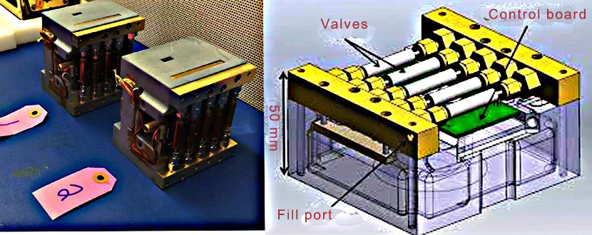
Aerospace 2021, 8, 186                                                                                             2 of 14

                         prospecting of our solar system. There are millions of liters of ice water on the Moon’s
                         surface [3,4]. Water on the Moon’s surface can provide oxygen for breathing, fuel for
                         propellants, and life support; therefore, water is a fundamental need when it comes to
                         living on alien planets, asteroids, natural satellites, etc. This precious liquid has a very good
                         sign at the THz frequency range. THz passive remote sensing technology has expanded
                         with the development of electronic components, especially Complementary metal–oxide–
                         semiconductor (CMOS) and Schottky diodes. THz, with its short wavelengths, are adapted
                         for appropriate detecting the small particles of water vapor and ice water. NASA has
                         recently been developing a 90/180 GHz radiometer hurricane mission. The radiometer
                         contains a fixed beam with dual canaliculated horns with a lens antenna to operate at
                         90 and 180 GHz frequency range for remote sensing of soil moisture [5,6]. THz’s application
                         for spectroscopy by analyzing the spreading of THz wavelength through the water vapor
                         has achieved a new level of high brightness, making is the most accurate model to absorb
                         across realms of water vapor in the frequency range of 0.2 to 1.45 THz [7]. Reference [8]
                         has two goals: firstly, to compare the amount of perceptible water vapor with ground-
                         based scanning radiometer with atmospheric radiation measurement, and secondly, to
                         compare the radiometric response of THz and microwave wavelengths to ice cloud and
                         water. A high-performance THz receiver for monitoring Jupiter’s ice moon has been
                         developed by the Chalmers University of Technology. Remote sensing of vapor and
                         gases by high-quality heterodyne receivers has been developed for monitoring planetary
                         missions [8]. The permittivity of water in the THz range enables the detection and imaging
                         of soil moisture capability. This property is utilized to make a laboratory experience for
                         remote sensing and mapping soil water moisture by a THz radiometer. Examples of THz
                         scanning for foods, agricultural productions, and polymers are reviewed in [9]. Low-
                         power, ultrashort THz pulses that radiate in the laboratory environment have enabled the
                         capability to detect signatures of water vapors [10]. An interesting method to determine
                         snow ice water, liquid water path, and integrated water vapor has been done by a neural
                         network algorithm based on an airborne millimeter and sub-millimeter radiometer [11].
                         MicroMAS a joined project of MIT/LL (Massachusetts Institute of Technology/Lincoln
                         Laboratory), a 3U CubeSat hosting a passive micro-sized spectrometer near 118.75 GHz
                         frequency has been used to observe the formation process of tropical cyclones, which
                         can determine cloud formation from small particles of water to a storm [12]. MiRaTA
                         CubeSat mission of MIT/LL (Massachusetts Institute of Technology/Lincoln Laboratory)
                         contains a constellation mission that was launched in early 2016 with tri-band radiometer at
                         frequencies (60, 183, and 206 GHz) for real-time remote sensing of Earth’s atmospheric [13].
                         Submillimeter Wave Astronomy Satellite (SWAS) with small satellites have been used to
                         determine water vapor on Jupiter and Saturn with multiband THz radiometry at center
                         frequencies 489 and 553 GHz, and experimental data have shown that THz radiometer
                         performed 1.5–2.5 times better than Infrared Space Observatory (ISO) for water vapor signs,
                         showing that water has better signs at THz waves [14].
                              In addition to theoretical concepts, the available hardware technologies must be consid-
                         ered to verify the feasibility of manufacturing the THz heterodyne spectrometer. CubeSat
                         system specifications present some constraints in size, mass, power generation, etc. Hence, the
                         THz heterodyne spectrometer requires high precision in design. In [15], a high-performance,
                         low-power-consumption, integrated THz Schottky receiver is presented for CubeSats, which is
                         a multilayer receiver with approximate dimensions of 25 × 25 × 40 mm and mass less than
                         250 g. This multi-frequency receiver operates at 557 GHz and 1100–1200 GHz. These frequency
                         ranges provide an excellent indication of ice water [16].
                               The previous paragraphs show that THz technology has attracted great attention, par-
                         ticularly in establishing their hardware on small satellites due to short THz wavelengths. In
                         this paper, we propose a scenario to discover water on the Moon by using THz heterodyne-
                         spectrometer by using a 3U CubeSat. This scenario includes three main segments: first, a
                         Cargo Microsatellite to transport four CubeSats into Low Lunar Orbit (LLO); second, four
                         CubeSats for lunar missions, which utilize a gas thruster in its Attitude Control System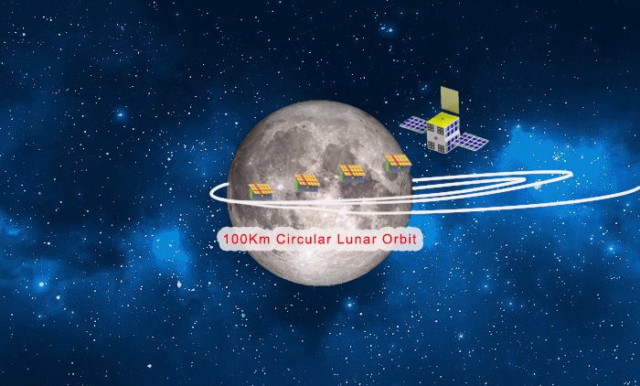
Aerospace 2021, 8, 186 3 of 14
where the magnetic-based Atitute Determination and Control Subsystem (ADCS) due to
low lunar gravity are useless; Third, The THz heterodyne-spectrometer payload, which
has new characteristics in its antennas specifications. A 3 × 3 array horn antenna interface
with CMOS switchers instead to patch array antennas. Horn antennas generally provide
more gain compared with patch array antennas, and we can still use options of an array
antenna. More details are explained in the next sections. In the paper, firstly, we present
mission objectives, then continue on mission scenario, and at the end, we present the
satellite project system with a THz radiometer for detecting ice water on the Moon for
creating the next generation of deep space exploration by using small satellites [17–22].
2. Mission Objective
Water is a vital source around the globe. Water is required for breathing, planting,
and agriculture, and all life depends on it. The Moon has attracted the greatest attention of
NASA, SpaceX, and most of the professional commercial space companies and investors
because the Moon is a window into human space exploration. Scientists have discovered
that there are millions of liters of ice water on the Moon’s poles [23]. Liquid water cannot
survive on the surface. Water quickly reacts chemically and turns into steam, and water
vapor goes to outer space. Therefore, the water on the Moon only exists in ice water form.
Some researchers have acknowledged that THz short wavelengths have a high potential to
identify water particles.
A CubeSat-sized THz heterodyne-spectrometer has some constraints, such as mass,
power, and dimension. NASA’s JPL has already developed a CubeSat-sized THz spectrom-
eter for detection of water on Jupiter and Saturn, and there are also three most updated
THz CubeSats that they operated for Earth’s atmosphere monitoring. Previous missions
assist us to develop the multi-channels THz spectrometer for determining ice water on the
Moon. This technology is a low-power consumer of CMOS or Schottky diodes based on
THz receiver systems [24–26].
For this mission, a cargo Microsatellite carries four 3U CubeSats into Low Lunar
Orbit and injects them into Low Lunar Orbit. After this, these five satellites make a
constellation to identify ice water locations on the Moon surface via a THz spectrometer.
The Cargo Microsatellite receives data from CubeSats and transmits them to Earth Deep
Space Network (DSN). Meanwhile, we already have LUMIO built by European Space
Agency [27] and MarCO built by NASA Jet Propulation laboratory [28], CubeSats for
prospecting of the Moon and Mars, respectively, but our project is proposing the followed
prospective beneficiaries: (1) using CubeSats for deep space missions, (2) developing
the CubeSat constellation for interplanetary missions, and (3) providing return samples
capability from other planets.
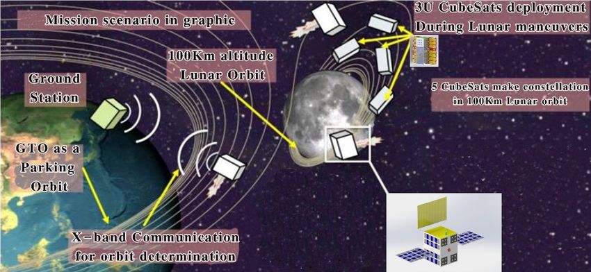
3. Lunar Orbit CubeSat Injector Scenario
The Lunar Orbit CubeSat Injector (LOCI) is a Cargo Microsatellite to transport four
third-party 3U CubeSats into Low Lunar Orbit (LLO). The LOCI must contain a gas thruster
(the model is Aerojet MPS-130 thruster) and four Poly Picosatellite Orbital Deployers
(P-POD) as the key requirements to transport the CubeSats from Earth orbit to LLO [29].
Additional explanations about system-level design are described in Section 4. The trajectory
route to LLO orbit requires four main thrusts series (see Figure 1):
1. Thrust near Geostationary Transfer Orbit (GTO)perigee to increase Geostationary
Orbit (GEO) orbit radius altitude.
2. Thrust near apogee to increase the radius of GTO perigee to ensure lunar orbit transferring.
3. Thrust and spiral to capture a lunar orbit.
4. Thrust to enter 100 km altitude circular lunar orbit.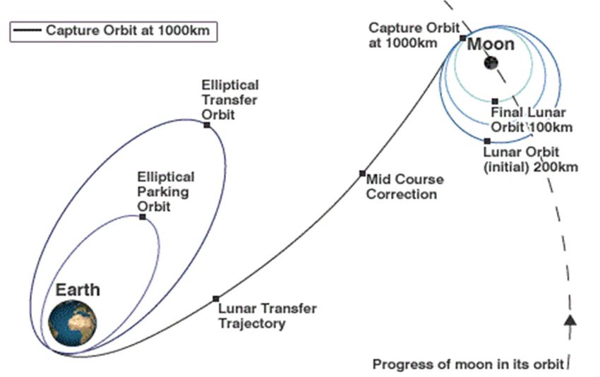
3. Thrust and spiral to capture a lunar orbit.
4. Thrust to enter 100 km altitude circular lunar orbit.
Aerospace 2021, 8, x 4 of 14
Aerospace 2021, 8, 186 4 of 14
3. Thrust and spiral to capture a lunar orbit.
4. Thrust to enter 100 km altitude circular lunar orbit.
Figure 1. LOCI concepts of operation.
Figure 1 shows LOCI’s scenario. After this, LOCI arrives 100 km LLO, the four third
party CubeSats enters into the orbit; at this time, LOCI has a camera in the front to take
Figure 1.
Figure 1. LOCI
LOCI concepts
concepts of of operation.
operation.
photo of CubeSats injection from P-PODs and transmits the image by X-band transmitte
to announce
Figure 1 shows
Figure Earth station,
showsLOCI’s scenario.the
which
LOCI’sscenario. AfterCubeSats
Afterthis, LOCI
this, have
LOCIarrives been100successfully
arrives km
100 LLO,
km LLO, theinserted
four fourinto LLO
thethird-
Figure
party
third-party 2 shows
CubeSats CubeSat
enters
CubeSats enters modes.
into the into theAfter
orbit; at thisthe
orbit; at deployment
time,
thisLOCI
time,has LOCI aphase,
has athe
camera in CubeSat
the
camera front
in the enters
to frontainto Saf
take
mode,
photo
to takeof aatCubeSats
this mode
photo the CubeSat
injection
of CubeSats from
injection actives
P-PODsfromand Electronic andPower
transmits
P-PODs the image
transmits Subsystem
by
theX-band
image (EPS) and On Board
transmitter
by X-band
transmitter
to announce
Data Handling toEarth
announce
station,
Subsystem Earth
whichstation,
(OBDH) which
and the
the CubeSats wait CubeSats
have been
until 15have
minbeen
successfully successfully
inserted
for batteries inserted
tointo
be LLO. charged
fully
into
FigureLLO.
and for 2 showsFigure
deployable 2 shows
CubeSat CubeSat
modes. Aftersuch
mechanisms modes. After
the deployment the
as UHF antennas deployment
phase, the and phase,
CubeSat
solar entersthe CubeSat
into Safe
cells spread properly
enters
mode, into
at Safe
this mode,
mode theat this
CubeSat mode the
actives CubeSat
Electronic actives
Power
Then, the CubeSat sends a beacon and enters Recovery mode. In Recovery mode, CubeSaElectronic
Subsystem Power(EPS)Subsystem
and On (EPS)
Board
and
Data On Board Data
Handling Handling
Subsystem (OBDH) Subsystem
and wait (OBDH)
until 15and minwait until 15 min
for batteries for batteries
Attitude Determination and Control Subsystem (ADCS) adjusts to thebeCubeSat’s
fully chargedorientatio
to
andbeforfully charged mechanisms
deployable and for deployable such as mechanisms
UHF antennas suchandassolar
UHFcellsantennas
spreadand solar
properly.
to nadir pointing
cells
attitude (the payload on the CubeSat operates only when orients to th
Then,spread
the CubeSatproperly.
sendsThen, the CubeSat
a beacon and enters sends a beacon
Recovery mode.andIn enters Recovery
Recovery mode,mode. CubeSat In
Moon’s
Recovery surface). After
mode, CubeSatand Recovery
Attitude mode
Determinationis properly accomplished,
and Control Subsystem the CubeSat
(ADCS) adjuststransmits
Attitude Determination Control Subsystem (ADCS) adjusts the CubeSat’s orientation
to nadir pointing attitude (the payload on the CubeSat operates only when orientsNormal
beacon
the CubeSat’sto the Microsatellite
orientation to nadir and enters
pointing Normal
attitude mode
(the payload(the next
on the mode).
CubeSat In to the mode
operates
Moon’s surface). After Recovery mode is properly accomplished, the CubeSat transmits a modes
the
only CubeSat
when waits
orients to for
the Ground
Moon’s Station
surface). (GS)
After commands
Recovery mode to
is enter
properly three functional
accomplished,
the CubeSat
beacon to thetransmits
Constellation mode, aCommunication
Microsatellite beacon
and to the Microsatellite
enters mode,mode
Normal andand (theenters
Payload Normal
next mode.
mode). Inmode
In all the
Normal (the next the Mi
modes,
mode,
mode).
the In Normal
crosatellite
CubeSat waits mode,
communicates the CubeSat
for Ground data
Station waits
relay for
(GS)between Ground
commands Station
to enter(GS)
CubeSats threecommands
and Ground
functional tomodes,
enter Payload
Station.
three
mode functional
Constellation
meansmode, modes,
the THz Constellation
Communication mode,
mode,Communication
heterodyne-spectrometer and Payload turnsmode. mode,
ON In and
and Payload
allbegins
the to mode.
modes, the Mi-
collect In
lunar sur
all the modes,
crosatellite the Microsatellite
communicates communicates data relay between CubeSats and Ground
face data, then saves the data data relay
on a 32 between
GB Secure CubeSats Digital and(SD)Ground
card.Station.
When the Payload
SD become
Station.
mode Payload
means mode
the THz means the THz heterodyne-spectrometer
heterodyne-spectrometer turns ON and begins turns ON and
to collect lunarbegins
sur-
full,
to
the
collect
CubeSat
lunar
enters
surface data,
Constellation
then saves the
mode data
to
on
transmit
a 32 GB
the
Secure
payload
Digital
data.
(SD)
Constellatio
card.
face data,
modethe means then saves the
either afull, data
new on a 32 GB Secure Digital (SD) card. When the SD becomes
When
full, the SD becomes
CubeSat thecommand
CubeSat mode
enters Constellation
has been
enters received fromtoGround
Constellation
to transmit themode payload transmit Station,
the payload
data. Constellation
and the Mi
crosatellite spreads
data. the received command to all CubeSats, or one offrom the CubeSats trans
modeConstellation
means either mode a newmeans
command eitherhasa been
new command
received from has been
Ground received
Station, andGround the Mi-
mits
Station, the payload
andspreads data to
the Microsatellite Microsatellite
spreads to relay
the received data
command to Ground
to all Station. From each
of mode
crosatellite the received command to all CubeSats, or one ofCubeSats,
the CubeSats or one trans-
satellites
the
mits
CubeSats
the payloadcantransmits
enter
dataSafe mode; at
the payload
to Microsatellite
dataSafe mode, dataall
to Microsatellite
to relay to subsystems
to relay data
Ground Station. turn OFF,
to Ground
From each the batteries ar
Station.
mode,
From each
charged,can mode,
andenter satellites
OBDH can enter Safe mode; at Safe mode, all subsystems turn OFF,
satellites Safegoes
mode; into power-down
at Safe mode. After
mode, all subsystems turneach
OFF, functional
the batteries mode,are the Cu
the batteries
beSats return areNormal
charged,mode and OBDH and goesuntil
stay into power-down
it receives mode.
GS After each functional
commands.
charged, and OBDH goes into power-down mode. After each functional mode, the Cu-
mode, the CubeSats return Normal mode and stay until it receives GS commands.
beSats return Normal mode and stay until it receives GS commands.
Figure 2.2.Mission
Figure2.
Figure Mission
MissionScenario.
Scenario.
Scenario.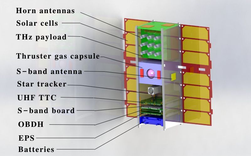
Aerospace 2021, 8, 186                                                                                          5 of 14

                         4. System-Level Design
                              Lunar water is water that has been found on the Moon. The research shows that
                         liquid water cannot survive on the Moon’s surface. The water vapor is decomposed by
                         sunlight, leaving oxygen and hydrogen lost to outer space. Scientists have conjectured
                         that ice water can exist on the Moon, and there are millions of liter of ice water on the
                         Moon’s poles [30]. Here, we present a CubeSat THz heterodyne spectrometer for the
                         identification of ice water on the Moon. This idea considers the capability of system-on-
                         chip THz communication and millimeter receiver for space exploration and remote sensing
                         of the Moon to detect water. The THz payload prepares technics and calibrations to provide
                         water sources to increase the potential of humans surviving in the harsh environment of
                         the Moon. In addition, the CubeSat platform plays a key role in accomplishing the mission.
                         A CubeSat has limitations in mass, size, and electrical power. A general CubeSat, for
                         example, a 3U CubeSat, has a maximum 10 kg mass subjected to Poly-Picosatellite Orbiter
                         Deployer (P-POD) launcher system standard. A standard CubeSat platform includes
                         Electrical Power Subsystem (EPS), On Board Data Handing (OBDH), Telemetry Tracking
                         and Command (TTC), Attitude Determination and Control Subsystem (ADCS), Thermal
                         Control Subsystem (TCS), Structure Design (Str), and thruster. The platform specifications
                         depend on the mission requirements [31].
                              Part of this paper includes a description of a cargo Microsatellite (named LOCI). LOCI
                         transports four third-body CubeSats into LLO. Meanwhile, many low-power consumer
                         thrusters have been built to be compatible with CubeSats, but in our design, we prefer
                         to utilize the CubeSats’ thruster only for ADCS, where a gravity-based ADCS system is
                         useless on the Moon. By using LOCI’s thrusters, the trajectory time from the Earth to
                         the Moon will be done more quickly. The paper mostly explains the CubeSat system, but
                         LOCI’s key subsystems are also illustrated.
                         4.1. Payload Design and Primary Sketch
                              Heterodyne spectrometers at millimeter and submillimeter frequency ranges are
                         widely utilized in Earth and lanetary science to identify the origins of galaxies and to
                         study the characteristics of Earth’s surface and atmospheric compositions [32]. HIFI [33],
                         MIRO [34], and MLS [35] are space-borne THz heterodyne-spectrometer examples that
                         already launched into the Earth’s orbit. These small satellites with millimeter spectrometry
                         missions and their functionalities in the Earth’s remote sensing missions provide the
                         background for upgrading current terrestrial THz spectrometer technologies for outer space
                         missions. In [35], a 183 GHz receiver with a tunable center frequency was manufactured
                         for remote sensing of atmosphere.
                              We present a miniaturized THz heterodyne-spectrometer, which contains three
                         10 × 10 cm electronic boards with 3.15 W total power consumption and 1 kg total mass.
                         The payload is compatible with the CubeSat platform standard; therefore, the payload
                         operates on the CubeSat and senses the ice water footprints on the Moon’s surface. NASA is
                         developing a spectrometer system with a frequency 300 up to 4700 GHz. The 500–600 GHz
                         frequency has responses for water, and the 509 to 590 GHz range has responses for water va-
                         por; this receiver is a CMOS-based RF circuit. Additionally, THz Schottky diodes receivers
                         present a high gain in performance, especially when cooled until −100 K. The THz Schottky
                         receiver offers a CubeSat platform suitable for 1U CubeSat. There are many advantages
                         of using THz receiver on small CubeSats. The motivation of this paper is to develop a
                         millimeter receiver for water vapor and ice water detection on the Moon. Water vapor
                         has an excellent response at frequency 557 GHz and in 1100–1200 GHz bands. A 557 GHz
                         spectrometer was the main target of the NASA SWAS mission. The first block diagram
                         for THz heterodyne-spectrometer is illustrated in Figure 3. It contains three main blocks,
                         Horn antennas switchers, 28 nm CMOS heterodyne RX, and 65 nm CMOS Spectrometer to
                         generate the spectrum out. Array horn antennas with 3 × 3 dimensions can provide higher
                         gain, increase the directivity, and steer a radio beam to point at different orientationss or
                         find the signal direction [36–38].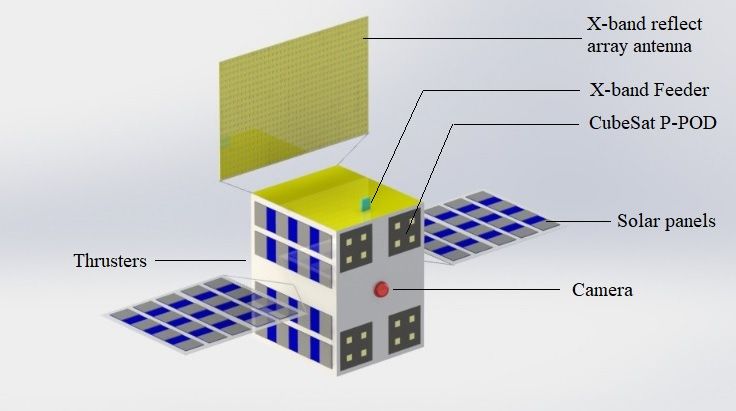
6 of 14
provide higher gain, increase the directivity, and steer a radio beam to point at diff
Aerospaceprovide
orientationss or find the signal direction [36–38].
2021, 8, 186 higher gain, increase the directivity, and steer a radio beam to point at different6 of 14
orientationss or find the signal direction [36–38].
Figure 3. THz Heterodyne-Spectrometer block diagram.
Figure 3. THz Heterodyne-Spectrometer block diagram.
References [39–42] confirm that the THz receiver for water detection is feasible
Figure 3. THz Heterodyne-Spectrometer
References [39–42] block diagram.
confirm that the THz receiver for water detection is feasible with a
a CubeSat platform, and state-of-the-art technology shows that by using Schottky di
CubeSat platform, and state-of-the-art technology shows that by using Schottky diodes or
aor a CMOS-based
CMOS-based receiver,receiver, we can implement
we can implement the proposed the
idea.proposed
We proposeidea. We propose a m
a multi-channel
References [39–42]
THz
confirm
channel THz
receiver
that the
receiver to
to determine
THz receiver
determine
water
for
water
vapor, ice
water
water,vapor,
detection
ice water,
and liquid
is
and
water; see
feasible
liquid
Figure
with
4. water; see Figu
a CubeSat platform, and state-of-the-art technology shows that by using Schottky diodes
or a CMOS-based receiver, we can implement the proposed idea. We propose a multi-
channel THz receiver to determine water vapor, ice water, and liquid water; see Figure 4.
Figure4. 4.
Figure Multichannel
Multichannel THzTHz heterodyne-spectrometer
heterodyne-spectrometer first sketch.
first sketch.
4.2. Lunar Orbit Insertion and Constellation
4.2. Lunar Orbit Insertion and Constellation
Three classes of orbits are considered for the project: libration orbit, perturbed Keple-
Three
rian orbit, andclasses
Keplerian of orbit.
orbitsOnlyare orbits
considered for the or
with repetitive project: libration
periodic orbit,with
characteristics perturbed
lerian
respect
Figure 4. Multichannel orbit, and Keplerian
THztoheterodyne-spectrometer orbit.
the Moon surface can be considered Only orbits with repetitive or periodic
as remote sensing orbits of the Moon. To
first sketch. character
consider Keplerian
with respect to theorbits,
Moon we surface
include Low
can Lunar Orbit (LLO)
be considered as and Elliptical
remote Lunar
sensing Orbitof the M
orbits
(ELO). LLO
To consider has a constant altitude with respect to the Moon surface
Keplerian orbits, we include Low Lunar Orbit (LLO) and Elliptical and a lower orbit Luna
4.2. Lunar Orbit Insertion and Constellation
period (usually it would be 2 h with alt = 100 km). If the altitude > 100, the Moon gravity
bit (ELO). LLO has a constant altitude with respect to the Moon surface and a lower
Three classes is
ofnot
orbits aregravity
the only considered for the
that affects thesatellite;
project:thelibration orbit,causes
Earth’s gravity perturbed Kep-to
the altitude
period (usually
becomes variant initsome
would be 2 h ELO
positions. withtypically
alt = 100have
km). If the apolune
a larger altitudealtitude
> 100, the
and Moon
a gr
lerian orbit, and Keplerian orbit.
is notperilune
the only Only
gravity orbits with
that affects repetitive or periodic
the satellite; the distance characteristics
Earth’s changes
gravityperiodically
causes the altitu
lower altitude; therefore, the spacecraft-to-the-Moon
with respect to theinbecomes
Moon surface
an orbitalvariant can be
in some
motion along considered
withpositions. as remote
ELO typically
a certain coverage sensing orbits
have a[43].
of lunar regions of
larger the Moon.
We apolune
have altitude a
chosen
To consider Keplerian
LLO
lowerorbits, welunar
as perilune
CubeSat include Low
remote
altitude; Lunar
sensing
therefore, Orbit
orbit
the (see (LLO) and
Figure 5). Elliptical
The
spacecraft-to-the-Moon Lunar
LOCI enters Or-
LLOchanges
distance and per
injects
bit (ELO). LLO has cally the
a constant CubeSats,
altitude
in an orbital and then the
with respect
motion group
along with of satellites
to the (the
Mooncoverage
a certain four CubeSats
surface and and
a lower
of lunar the cargo
orbit[43]. We
regions
microsatellite) work together and form a lunar constellation.
period (usually it would
chosenbe 2 haswith
LLO alt = lunar
CubeSat 100 km). If the
remote altitude
sensing > 100,
orbit the Moon
(see Figure gravity
5). The LOCI enters
is not the only gravity that affects the satellite; the Earth’s gravity causes the altitude toand the c
and injects the CubeSats, and then the group of satellites (the four CubeSats
becomes variant inmicrosatellite)
some positions.workELO
together and form
typically havea lunar constellation.
a larger apolune altitude and a
lower perilune altitude; therefore, the spacecraft-to-the-Moon distance changes periodi-
cally in an orbital motion along with a certain coverage of lunar regions [43]. We have
chosen LLO as CubeSat lunar remote sensing orbit (see Figure 5). The LOCI enters LLO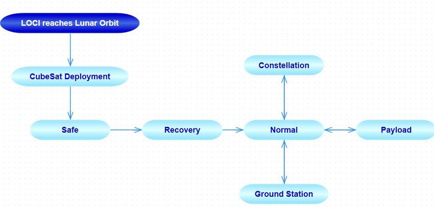
Aerospace2021,
Aerospace 2021,8,8,186
x 77 of
of 14
14
Aerospace 2021, 8, x 7 of 14
Figure 5. LOCI Low Lunar Orbit insertion.
Figure 5.
Figure LOCI Low
5. LOCI Low Lunar
Lunar Orbit
Orbit insertion.
insertion.
LLO orbit
LLO orbitinsertion
insertionsequence
sequence contains
contains several
severallarge largemaneuvers
maneuversfollowed
followedby by asmall
small
LLO
thrust madeorbitbyinsertion
the LOCI sequence
thrusters.contains
All several large
maneuvers maneuvers
typically take 867followed
days to by aa small
capture the
thrust made by the LOCI thrusters. All maneuvers typically take 867 days to capture the
thrust made
LLOorbit by
orbit with the
with aa 100 LOCI
100 km thrusters.
km altitude. All maneuvers
altitude. Typically,
Typically,each
eachorbit typically take
orbitmaneuver 867
maneuvertakes days
takes38 to
38min capture
minusing the
usingfour
four
LLO
LLO
LOCIorbit with a 100
thrusters. Duekm to altitude. Typically, eachinorbit
several contingencies
contingencies maneuver
the Earth-to-Moontakestrajectory,
Earth-to-Moon 38 min using LOCIfouris
LOCI thrusters. Due to several in the trajectory, LOCI is
LOCI thrusters.
planned to have Due
suchtolong
several
orbitcontingencies
maneuvers toinminimize
the Earth-to-Moon
the trajectory,
third-body effect LOCI
on largeris
planned to have such long orbit maneuvers to minimize the third-body effect on larger
planned to
capture orbit.haveReference
orbit. such long[44]orbit maneuvers
estimated timetoforminimize
for the third-body
lunar orbit
orbit capture with
witheffect
LOCI.on At
larger
this
capture Reference [44] estimated time lunar capture LOCI. At this
capture
stage, orbit.
when Reference
the LOCI [44]
captures estimated
the lunartime for
orbit, itlunar orbit
deploys capture
four with
CubeSats LOCI.
(see At
Figure this
6) to
stage, when the LOCI captures the lunar orbit, it deploys four CubeSats (see Figure 6)
stage,
reach when the
different LOCI
orbits captures
for for the
prospecting lunar orbit,
of the it deploys four CubeSats (see Figure 6) to
to reach different orbits prospecting of Moon
the Moon for ice
forwater by using
ice water their THz
by using their heter-
THz
reach
odynedifferent orbits for prospecting of the Moon for ice water by using their THz heter-
spectrometers.
heterodyne spectrometers.
odyne spectrometers.
Figure6.6. LOCI
Figure LOCILow
LowLunar
LunarOrbit
Orbitinsertion.
insertion.
Figure 6. LOCI Low Lunar Orbit insertion.
4.3.
4.3. Attitude
Attitude Determination
Determination and
andControl
ControlSubsystem
Subsystem
4.3. Attitude Determination and Control Subsystem
Outer
Outer space environmentproperties
space environment propertiespresent
presentspecial
special characteristics
characteristics thatthat require
require a
a spe-
cificOuter
specific
ADCS space
ADCS environment
system.
system. AA properties present
magnetorquer-based
magnetorquer-based special
ADSC
ADSC characteristics
system
system isis useless that
useless in
in require
lunar
lunar a spe-
conditions
conditions
cific
due ADCS
due toto the system.
thelow
low A magnetorquer-based
magnetic
magnetic field
fieldaround
aroundthe ADSChence,
theMoon;
Moon; system
hence, is useless in
aadedicated
dedicated lunarsystem
ADCS
ADCS conditions
system for
foraa
due
lunar to the low magnetic field around the Moon; hence, a dedicated ADCS
lunar mission is a Reaction-Wheel-based control system; however, the RW systemstill
mission is a Reaction-Wheel-based control system; however, the RW system
system for a
still
lunar
requiresmission is a Reaction-Wheel-based control system; however, the
requires a gas thruster to desaturate the momentum management systems [44]. Table 11
a gas thruster to desaturate the momentum management systemsRW system
[44]. still
Table
requires
shows
showsLOCI’sa gas ADCS
LOCI’s thruster
ADCSitemsto desaturate
items list.
list. the momentum management systems [44]. Table 1
shows LOCI’s ADCS items list.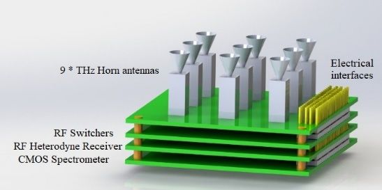
Table 1. LOCI’s ADCS items list.
Aerospace 2021, 8, 186 8 of 14
Microsatellite Characteristics
Components Qty Model
sun sensor
Table 1. LOCI’s ADCS items list. 2 SolarMEMS nanoSSOC-D60
Star tracker 2 Hyperion ST400
Microsatellite Characteristics
ComponentsIMU Qty 1 Sensonor
Model STIM 300
Thruster
sun sensor 2 2 SolarMEMSAerojet MPS-130
nanoSSOC-D60
Star Reaction
tracker Wheels 2 3 Hyperion TBD
ST400
IMU 1 Sensonor STIM 300
Thruster 2 Aerojet MPS-130
LOCI requires
Reaction Wheels high accuracy in3 Earth-to-Moon orbit trajectory
TBD and CubeSats
deployment; hence reaction wheels are required as part of LOCI’s ADCS, but for the
beSats’
LOCIADCS,
requiresthe cold
high gas thruster
accuracy is sufficient.
in Earth-to-Moon The CubeSat
orbit trajectory Attitudeorbit
and CubeSats Determin
deployment; hence reaction wheels are required as part of LOCI’s ADCS,
Control Systems are similar to LOCI components, except for two items, star tracker but for the
CubeSats’
thruster.ADCS,
In [45],the cold gas
a cold gasthruster
thruster is sufficient. The CubeSat
for interplanetary Attitude
mission byDetermination
UT Austin is develo
Control Systems are similar to LOCI components, except for two items, star tracker, and
see Figure 7. The project is named INSPIRE. INSPIRE Attitude Direction Control onl
thruster. In [45], a cold gas thruster for interplanetary mission by UT Austin is developed;
lizes
see cold7.gas
Figure Thethruster.
project is The
namedstar trackerINSPIRE
INSPIRE. that was selected
Attitude is [46]Control
Direction item. A small sat
only
compact-sized
utilizes star tracker.
cold gas thruster. INSPIRE
The star is awas
tracker that 3Unit CubeSat
selected is [46]similar
item. A to oursatellite
small proposed sys
The thruster only occupies 6.4 × 9.0 × 9.2 cm, includes the circuit hardware, gas tank
compact-sized star tracker. INSPIRE is a 3Unit CubeSat similar to our proposed system.
The thruster
nozzles. only
The thruster 6.4 × 9.0 ×power
occupiescomputer 9.2 cm, includes the circuit
consumption hardware,
is 0.2 W, andgas tank,nozzle
each and consu
nozzles. The thruster computer power consumption is 0.2 W, and each nozzle consumes
5.2 W upon which it opens. This means when all four nozzles open, the power consu
5.2 W upon which it opens. This means when all four nozzles open, the power consumption
tion is approximately 21 W, but since every thrust only operates in milliseconds, it is
is approximately 21 W, but since every thrust only operates in milliseconds, it is compatible
patible
with with the
the power power of
generation generation
a 3U CubeSat.of a 3U CubeSat.
Figure7. 7.
Figure CubeSat
CubeSat coldcold gas thruster.
gas thruster.
4.4. Telemetry Tracking and Command Subsystem
4.4. Telemetry Tracking and Command Subsystem
When a satellite launches into orbit, the only communication method is the TTC
Whenhence,
subsystem; a satellite launchesisinto
this subsystem orbit,subsystem
a crucial the only andcommunication
must be chosen method is the TTC
accurately.
system;
LOCI’s TTC hence, this subsystem
requirements is a(1)crucial
are as follows: subsystem
the mother ship shouldand be must
able to be chosen
transfer all accura
CubeSats
LOCI’s TTCdata to the ground station
requirements are asin the shortest
follows: 1)time
the possible;
mother (2)shiptheshould
CubeSats bemust
ablebeto transf
able to find the
CubeSats data mother
to theship (LOCI)
ground without
station in the
theneed for pointing
shortest position;2)
time possible; (3)the
CubeSats
CubeSats mu
should have a supporting radio link with low bit rate when S-band link is faced with
able to find the mother ship (LOCI) without the need for pointing position; 3) Cub
malfunctioning; (4) CubeSats must be able to transfer their data to the ground station
ifshould
motherhave
ship acommunication
supporting radio link link with
is faced lowmalfunctioning.
with bit rate when S-bandTable 2 link is faced
checks the with
functioning;
estimated bits in4)advance
CubeSats mustthe
to realize bebandwidth
able to transfer theirlinks
of the radio datathat
to have
the ground station if mo
been selected
ship
for communication
appropriate LOCI andlink is faced with malfunctioning. Table 2 checks the estimated
the CubeSats.
In the lunar
in advance mission,the
to realize thebandwidth
visibility of the ground
of the radio station
linksinthat
critical
havephases
beencould be for ap
selected
considered around 18 min at minimum; however, for a lunar orbit, visibility time would
priate LOCI and the CubeSats.
be large enough. S-band Up/Down link bit rate is 6 Mbps, X-band 400 Mbps, and Ka-
band >400 Mbps, and, as can be seen in Table 2, the maximum downlink data volume is
1.6 GB. Therefore, X-band is an appropriate choice for direct transferring data to DSN. The
mother ship utilizes high-gain X-band reflect array antenna for ground station transmission,Aerospace 2021, 8, 186 9 of 14
omini-direction S-band antenna for constellation link, and UHF for supporting links in any
malfunctioning phase [47,48].
Table 2. Estimated Up/Down link data values.
Uplink Data Estimation
Data Value
Telemetry 160 × 103
Software patch 2 × 10⁶
Margin 5.4 × 10⁵
Max data 2.7 × 10⁶
Typical data 1.4 × 10⁶
Downlink data estimation
Payload data 26 × 107
Engineering data 8 × 10³
Margin 6.5 × 10⁷
Total downlink data per satellite 33.6 × 10⁷
Total 5 satellites downlink data with mother ship 168 × 107
The CubeSats have two back-to-back S-band antennas to be able to transmit payload
and telemetry data without changing their orientation to the microsatellite. Omini-direction
UHF is the supporting link in circumstances that the S-band transmitter is faced with
malfunctioning (it could be considered a critical phase in a satellites scenario). Then the
CubeSat transmits data through UHF transceiver; however, the data rate is very low, but
less is better than nothing [49].
4.5. Electrical Power Subsystem Design
The majority of CubeSat projects calculate their power consumption according to
simple Formula (1), which calculates the amount of power generation for a single solar cell:
p = ηn .S.A. sin φ (1)
where p is power generated by a solar cell, S [W/m2 ] sunlight power density, A is area
of solar cell, ηn solar cell efficiency, and φ is angle of sunlight irradiations with respect to
the solar cell panel [50]. Since the project is for a lunar mission, the S is approximately
1415.54 W/m2 with an average orbit time of 113 min on lunar orbit, according to [51], A is
3U CubeSat standard solar cells referenced from CubeSat shop company with ηn efficiency
30%. A solar cell power generation is very dependent on the CubeSat attitude orientation.
In [51], it was claimed that there are three different attitude orientation scenarios, free-
orientation scenario, nadir-pointing scenario, and sun pointing scenario. Each of these
orientations provides different power levels; for example, sun pointing generates maximum
solar cells power capability, in free orientation, considering the average of solar cell power
generation capability [51]. The system requires the satellites to always point to the Moon
surface; therefore, the nadir-pointing scenario is our system attitude orientation scenario.
The authors of [51] say that a 3U solar cell with nadir-pointing orientation approximately
generates 5.84 W power. Table 3 estimates a CubeSat power budget. It helps to select the
number of solar cells and their mechanism, either a body-mounted or deployable solar
cells mechanism.
According to Table 3, body-mounted solar cells cannot provide sufficient maximum
power consumption of the CubeSat; therefore, a deployable mechanism should be consid-
ered. To conclude, the functionality of Electrical Power Subsystem should be a deployable
mechanism with 17.52 W power generation on average.Aerospace 2021, 8, 186 10 of 14
Table 3. CubeSat power budget.
CubeSat Subsystem & Their Power Usage
Item P(W) Duty Cyclex/113 min
OBDH 0.1 113/113
UHF transceiver TX/RX 4/0.48 5/113
S-band transceiver TX/RX 12/1.2 3/113
ADCS MCU 0.2 113/113
Thruster 21 1/113
Sun sensor 0.006 113/113
Star tracker 1 113/113
IMU 0.01 113/113
THz Payload 3.15 113/113
Power usage in scenario
Mode Active subsystems power usage per mode (W)
safe OBDH, ADCS, MCU, ADCS sensors 1.616
Recovery OBDH, ADCS, MCU, ADCS sensors, Thruster 2
Normal OBDH, ADCS, MCU, ADCS sensors, UHF RX/TX 2.16
Constellation OBDH, ADCS, MCU, ADCS sensors, S-band, Thruster 2.276
Mode Active subsystems Power usage per mode (W)
Payload OBDH, ADCS, MCU, ADCS sensors, THz 5
4.6. Structure Design
The mass center of the CubeSats must stay within 2 cm measured from the XY plane
in the z geometric direction. Since the structure protects the satellite from the harsh
environment of space and the launch vehicle’s vibration forces, some standards are required
for designing a CubeSat structure. All deployable mechanisms, such as antenna and solar
cells, must stay all together during launch and injection phases. Another factor that
affects structure characteristics is mass budget: the mass budget is a priority that must
be considered before designing the CubeSat structure. Table 4 shows the CubeSat mass
budget. The first face inserted into P-POD is the –Z side. The project includes two principal
bodies, LOCI and the 3U CubeSats. LOCI contains four P-PODs, a camera on the +X side,
the nozzles of the thruster on –X side, two 3U deployed solar cells on +Y,-Y sides, and a
reflect array on the +Z side. The CubeSat includes two 3U deployable solar cells on the
±Y side; under them, there are two S-band patch antennas to radiate omnidirectional radio
signals. By using that layout, the CubeSats constellate without pointing orientation to
LOCI, star tracker module is on +Z side, and THz spectrometer is positioned to the Moon
surface, means on the–Z side (see Figure 8, CubeSat structure; Figure 9, LOCI structure).
The dimensions of LOCI are 50 × 50 × 70 cm.
Table 4. CubeSat mass budget.
Subsystem
Item Mass (gr) Quantity
Thruster 500 1
3U solar cells 150 3
20Whr battery and Hardwares 350 1
Main MCU 100 1
UHF transceiver 75 1
UHF ant 50 1
S-band transceiver 132 1
S-band ant 75 2
Star tracker 250 1
Structure 304 1
THz payload 400 1
Total mass 2761
Margin 239S-band transceiver 132 1
S-band transceiver 132 1
S-band ant 75 2
S-band ant 75 2
Star tracker 250 1
Star tracker 250 1
Structure 304 1
Structure 304 1
THz payload 400 1
Aerospace 2021, 8, 186 THz payload 400 1 11 of 14
Total mass 2761
Total mass 2761
Margin 239
Margin 239
Figure 8.
8. CubeSat characteristics.
characteristics.
Figure 8. CubeSat
Figure CubeSat characteristics.
Figure 9. LOCI Microsatellite characteristics.
Figure9.
Figure 9. LOCI
LOCI Microsatellite
Microsatellitecharacteristics.
characteristics.
5. Conclusions
In this paper, we proposed an interplanetary mission with a cargo Microsatellite. We
already know that there are missions such as MarCO (Mars Cube One), a 6U CubeSat
targeting Mars, but a microsatellite has more electrical power, thruster fuel, and mass
capacities; consequently, the mission can proceed farther into deep space and perform
it in a shorter amount of time. A CubeSat with an electrical thruster reaches the Moon
in approximately 900 days, and a microsatellite reaches it in 300. A microsatellite can
transport a CubeSat into deep space, and the mission period could be done three times
faster; in addition, the microsatellite could be developed with system characteristics such
as a thruster and its fuel bank. Then, the microsatellite can use the gravity assist concept
and travel to different planets and deliver CubeSats to each planet. For example, the
microsatellite gest assistance from Earth’s gravity and then goes toward Venus’s orbit
to deliver a CubeSat and then gets assistance from Venus’s gravity and thrusts to Mars
to deliver another CubeSat. All scenarios are possible with our proposed microsatellite
platform with a small change in the system. On the other hand, the proposed 3U CubeSat
is a platform for any interplanetary missions that it is required to be accomplished using
a CubeSat. The constellation with five satellites gives us this opportunity to cover the
Moon’s surface monitoring two or three times per day, and the microsatellite with an
x-band high data rate transmitter transfers the collected data to the Earth’s ground stationAerospace 2021, 8, 186 12 of 14
with a small amount of time delay. Here, we proposed a kind of innovative THz heterodyne
spectrometer for water identification. The payload has array horn antennas. The benefit of
this layout is higher gain. We could have used an array patch antenna, but the maximum
gain that can be reached using array patch antennas is approximately 5–6 dB, while
that of a horn antenna is typically around 10–20 dB, which gives us better options to
receive signals from the Moon’s surface. To summarize, with water, we can complete
interplanetary tours to prospect unknown planets, especially with artificial satellites as
pioneers and CubeSats because of their cheap price and fast operation and ability to
perfectly accomplish such missions. However, current CubeSat thruster technologies do
not allow them to be fast-traveling objects, and this is the only weakness. Hence, we
consider the microsatellite to transport the CubeSats, so that weakness is improved by
the cargo microsatellite. The constellation provides more data in less time. We targeted
water detection on the Moon because we believe the Moon is a window for the future of
interplanetary missions. The Moon is one of the extraterrestrial natural satellites attracting
scientists’ attention to discover outer space. Spacecraft propellants refueling, plants growth,
and oxygen for breathing all are possible with water. Water is life, and this scenario has
been defined to find it.
Author Contributions: In this project, I have two colleages that assist me on this paper. Their
contributions with me are as follows: Conceptualization by, V.R.; methodology by, V.R.; software by,
V.R. and M.K.T.; validation by, W.H. and V.R.; formal analysis by, W.H.; investigation by, V.R. and
M.K.T.; resources by, V.R.; data curation by, V.R. and W.H.; writing—original draft preparation by,
V.R.; writing—review and editing by, V.R.; supervision by, Hu Weidnong; project administration
by, V.R. and W.H.; funding acquisition by W.H. All authors have read and agreed to the published
version of the manuscript.
Funding: This research received no external funding.
Institutional Review Board Statement: Not applicable.
Informed Consent Statement: Not applicable.
Data Availability Statement: The data that support the findings of this study are openly available in
Yanghyo, K., et al at http://doi:10.1109/TTHZ.2019.2910988, reference number [36].
Conflicts of Interest: Vahid Rastinasab, Weidong Hu and Mohammad Kazem Tahmasebi declare
that they have no conflict of interest.
References
1. Pablo, A.; Calla, G.; Dan, F.; Chris, W.; Bethany, D. Low-Cost Asteroid Mining Using Small Spacecraft. In Proceedings of the
International Astronautical Congress (IAC), Adelaide, Australia, 24 September 2017.
2. Eliza, S.; Glenn, Z. The Coming the Moon rush: Technology, billionaires, and Geopolitics will all help get us back to the Moon,
but they will not be enough to let us live there indefinitely. IEEE Spectr. 2019, 56, 22–25.
3. Wieger, G.W.; Joep, W.; Wilfred, F.; Rinie, K.; Paul, V. Can Plants Grow on Mars and the Moon: A Growth Experiment on Mars
and Moon Soil Simulants. In Proceedings of the 58th Annual Symposium of the International Association for Vegetation Science
(IAVS): Understanding Broad-Scale Vegetation Patterns, Brno, Czech Republic, 19–24 July 2015.
4. Radhika, R.; William, W.E.; Fatemeh, A.; Ramon, M.R.; Frank, P.; Scott, B. Survey of Inter-Satellite Communication for Small
Satellite Systems: Physical Layer to Network Layer View. IEEE Commun. Surv. Tutor. 2016, 18, 2442–2473.
5. Gagliano, J.A.; Platt, R.H. An Upward Looking Airborne Millimeter Wave Radiometer for Atmospheric Water Vapor Sounding
and Rain Detection. Soc. Photo Opt. Instrum. Eng. (SPIE) 1985, 544, 112–117.
6. Martin, V.E.; Fattinger, C.; Grischkowsky, D. Terahertz time-domain spectroscopy of water vapor. Opt. Lett. 1983, 14, 1128–1130.
7. Phys.org. Available online: https://phys.org/news/2013-10-terahertz-sensor-aiming-jupiter-moons.html (accessed on 7 October 2013).
8. Renju, R.; Suresh, C.; Nizy, R.; Tinu, M.; Antony, A.; Krishna, K. Microwave radiometer observations of interannual water vapor
variability and verical structure over a tropical station. J. Geophys. Res. Atmos. 2015, 120, 4585–4599. [CrossRef]
9. Qu, F.; Nie, P.; Lin, L.; Cai, C.; He, Y. Review of theoretical methods and research aspects for detecting leaf water conent using
terahertz spectroscopy and imaging. Int. J. Agric. Biol. Eng. 2018, 11, 27–34.
10. Joseph, S.M.; Yihong, Y.; Mahboubeh, M.; Grischkowsky, D. THz detection of small molecule vapors in the atmospheric
transmission windows. Opt. Express 2012, 20, 6788–6807.
11. Manfred, B.; Stuart, F.; Patrick, E.R.; Chawn, H.; Martian, B.; Stefan, A.B.; Manfred, B. Retrieval of an ice water path over the
ocean from ISMAR and MARSS millimeter and submillimeter brightness temperatures. Atmos. Meas. Tech. 2018, 11, 611–632.Aerospace 2021, 8, 186 13 of 14
12. Blackwell, W.; Allen, G.; Galbraith, C.; Hancock, T.; Leslie, R.; Osaretin, I.; Retherford, L.; Scarito, M.; Semisch, C.; Shields, M.; et al.
Nanosatellites for Earth Environmental Monitoring: The MicroMAS Project. In Proceedings of the Small Satellite Conference,
Rome, Italy, 5–9 March 2012.
13. Blackwell, W.; Cahoy, K. Small Satellite Constellation for Data Driven Atmospheric Remote Sensing. In Proceedings of the
International Conference on Dynamic Data-Driven Environmental System Science, Cambridge, MA, USA, 5–7 November 2014.
14. Bergin, E.A.; Lellouch, E.; Harwit, M.; Gurwell, M.A.; Melnick, G.J.; Ashby, M.L.N.; Chin, G.; Erickson, N.R.; Goldsmith, P.F.;
Howe, J.E.; et al. Submillimeter Wave Astronomy Satellite Observations of Jupiter and Saturn: Detection of 557 GHz Water
Emission from the Upper Atmosphere. Astrophys. J. 2000, 539, L147. [CrossRef]
15. NTRS—NASA Technical Reports Server. Available online: https://ntrs.nasa.gov/citations/20170011080 (accessed on 17
December 2019).
16. Peter, S. Advanced Schottky Diode Receiver Front-Ends for Terahertz Applications. Ph.D Thesis, Chalmers University of
Technology, Goteborg, Sweden, May 2011.
17. Weng, C.; Liu, L.; Gao, T.; Hu, S.; Li, S.; Dou, F.; Shang, J. Multi-Channel Regression Inversion Method for Passive Remote Sensing
of Ice Water Path in the Terahertz Band. Atmosphere 2019, 10, 437. [CrossRef]
18. William, J.B. Millimeter-Wave Reciever for Low-Cost Cubesat Platforms. In Proceedings of the IEEE MTT-S International
Microwave Symposium, Phoenix, AZ, USA, 17–22 May 2015.
19. NASA to Launch Swarms of Small, Earth-Observing Satellites. Available online: https://www.space.com/34644-nasa-small-
satellites-earth-science.html (accessed on 8 November 2016).
20. Steven, C.; Resing, T.C.; Gaier, C.D.K.; Chandraskar, V.; Shannon, T.B.; Sharmila, P.; Boon, H.L.; Susan, C.v.d.H.; Tristan, S.L.;
Ecuyer, C.; et al. Overview of Temporal Experiment for Storms and Tropical System (TEMPEST) CubeSat Constellation Mission.
In Proceedings of the IEEE MTT-S International Microwave Symposium, Phoenix, AZ, USA, 17–22 May 2015.
21. Kerri, C.; Anne, M.; Weston, M.; Timothy, C.; William, J.B.; Rebecca, B. Development of the Microwave Radiometer Technology
Acceleration (MiRaTA) CubeSat for all-weather atmospheric sounding. In Proceedings of the IEEE International Geoscience and
Remote Sensing Symposium (IGARSS), Milan, Italy, 26–31 July 2015.
22. Freeman, J.W.; Hills, H.K., Jr.; Lindeman, R.A.; Vondrak, R.R. Observation of water vapor ions at the lunar surface. Moon 1972,
8, 115–128. [CrossRef]
23. Spudis, P.D.; Bussey, D.B.J.; Baloga, S.M.; Cahill, J.T.S.; Glaze, L.S.; Patterson, G.W.; Raney, R.K.; Thomson, T.W.; Ustinov, E.A.
Evidence for water ice on the Moon: Result for anomalous polar craters from the LRO Mini-RF imaging radar. J. Geophys. Res.
Planets 2013, 118, 2016–2029. [CrossRef]
24. Mahesh, A. Lunar Water: A Brief Review. Earth Moon Planets 2010, 107, 65–73.
25. Groppi, C.; Hunter, R.; Baker, C. Highly Integrated THz Receiver Systems for Small Satellite Remote Sensing Applications. NASA
Technical Reports Server. 2017. Available online: https://techport.nasa.gov/view/94030 (accessed on 1 August 2018).
26. Jonathan, H.; Christopher, G.; Choonsup, L.; Robert, L.; Philip, M.; Phil, P.; Jose, S. Integrated Schottky Receiver for Small Satellite
Deployment. In Proceedings of the 29th IEEE International Symposium on Space THz Technology (ISSTT2018), Pasadena, CA,
USA, 31 July 2018.
27. Imran, M.; Jose, S.; Christine, P.C.; Josep, M.J. THz Technology for Space Communications. In Proceedings of the Asia-Pacific
Microwave Conference (APMC), Kyoto, Japan, 6–9 November 2018.
28. Jamnejad, V. A dual band telescope for microwave instrument on Rosetta orbiter (MIRO). In Proceedings of the IEEE Aerospace
Conference, Snowmass, CO, USA, 7 March 1999.
29. Armen, P.; Alessandro, G. CubeSat evolution: Analyzing CubeSat capabilities for conducting science missions. Prog. Aerosp. Sci.
2017, 88, 59–83.
30. Ana, M.C.; Diogene, A.D.; Francesco, T. Orbit Design for LUMIO: The Lunar Metroid Impacts Observer. Fundam. Astron. J. Front.
Astron. Space Sci. 2018, 5, 29.
31. 6U CubeSat Design Specification Rev. PROVISIONAL, The CubeSat Program, Cal Poly SLO. Available online: https://explorers.
larc.nasa.gov/APMIDEX2016/MO/pdf_files/12-6U_CDS_2016-05-19_Provisional.pdf (accessed on 20 April 2016).
32. Marcin, K.; Marcin, G.; Grzegorz, P. Global database of direct solar radiation at the Moon’s surface for lunar engineering purposes.
In Proceedings of the VII Conference SOLINA Sustainable Development: Architecture-Building Construction-Environmental
Engineering and Protection Innovative Energy-Efficient Technologies-Utilization of Renewable Energy Sources, Polańczyk,
Poland, 19–23 June 2018.
33. Ivo, V.; Ales, V. Efficient and Reliable Solar Panels for Small CubeSat Picosatellites. Int. J. Photoenergy 2014, 2014, 537645.
34. Yanghyo, K.; Senior, M.; Yan, Z.; Theodore, J.R.; Senior, M.; Deacon, J.N.; Goutam, C. A 183-GHz InP/CMOS-Hybrid Heterodyne-
Spectrometer for Spaceborne Atmospheric Remote Sensing. IEEE Trans. Terahertz Sci. Technol. 2019, 9, 313–334.
35. De Graauw, T.; Helmich, F.P.; Phillips, T.G.; Stutzki, J.; Caux, E.; Whyborn, N.D.; Dieleman, P.; Roelfsema, P.R.; Aarts, H.;
Assendorp, R.; et al. The Herschel-heterodyne instrument for the far-infrared. Astron. Astrophys. 2010, 518, L6. [CrossRef]
36. Mark, B. Mission Design for the Lunar Reconnaissance Orbiter. In Proceedings of the 29th Annual Aas Guidance and Control
Conference, Breckenridge, CO, USA, 4–8 February 2006.
37. Tanvir, I.H.; Kamal, H.; Shihabul, I.; Al-Amin, C. Design and Performance Analysis of Microstrip Array Antennas with Optimum
Parameters for X-band Application. International J. Adv. Comput. Sci. Appl. 2011, 2, 81–87.Aerospace 2021, 8, 186 14 of 14
38. Cristian, I.C.; Loan, E.L.; Leonardus, P.L. Design Considerations in Sparse array antennas. In Proceedings of the European Radar
Conference, Manchester, UK, 13–15 September 2006.
39. Imran, M.; Choonup, L.; Erich, S. THz Diode Technology: Status, Prospects, and Applications. Proc. IEEE 2017, 105, 990–1007.
40. Waydo, S.; Henry, D.; Campbell, M. CubeSat Design for LEO-Based Earth Science Missions. In Proceedings of the IEEE Aerospace
Conference, Big Sky, MT, USA, 9–16 March 2002.
41. Sara, S.; Benjamin, L. Optimization of cubeSat System-Level Design and Propulsion System for Earth-Escape Mission. J. Spacecr.
Rocket 2015, 52, 1009–1020.
42. Gaidis, M.C. Space-based applications of far infrared systems. In Proceedings of the 8th International Conference on Terahertz
Technology, Darmstadt, Germany, 31 July 2000.
43. Álvaro, R.C.; James, B.; Francesco, T. Attitude Control for the Lumio Cubesat in Deep Space. In Proceedings of the 70th
International Astronautical Congress, Washington, DC, USA, 21–25 October 2019.
44. Rodrigo, C.A.; Azhan, S.; Umunna, R.J.; Örger, N.C.; Quesada, M.R.; Morales, R.R. Lunar Orbiter CubeSat Injector. In Proceedings
of the Mission Idea Contest 4th, Japan, Tokyo, 3 July 2015.
45. Travis, K.; Imken, T.; Stevenson, H.; Glenn, L.E. Design and Testing of a Cold Gas Thruster for an Interplanetary CubeSat Mission.
J. Small Satell. 2015, 4, 371–386.
46. Mikhail, P.; Marat, A.; Anton, B.; Oleg, S.S.; Maksim, T.; Andrey, Z. Star tracker on chip. In Proceedings of the 27th Annual
AIAA/USU Conference on Small Satellites, CubeSat Developers’ Workshop, San Luis Obispo, CA, USA, 1 August 2013.
47. Vahid, R.N.; Hu, W. Implementation and Design of RF-Front-End Telemetry Tracking and Command Subsystem of a CubeSat
with 500-km Altitude. IEEE J. Miniat. Air Space Syst. 2020, 2, 43–47.
48. Nascetti, A.; Pittella, E.; Teofilatto, P.; Pisa, S. High-Gain S-band Patch Antenna System for Earth-Observation CubeSat Satellites.
IEEE Antennas Wirel. Propag. Lett. 2014, 14, 434–437. [CrossRef]
49. Nacer, C.; David, G.O.; Matthew, J.R.; Richard, E.H.; John, D.B.; David, J.B.; Thomas, A.C. A Review of CubeSat Antennas: From
Low Earth Orbit to Deep Space. IEEE Antennas Propag. Mag. 2019, 61, 37–46.
50. Shailesh, N.; Subhashish, B. Flexible Electrical Power System Controller Design and Battery Integration for 1U to 12U CubeSats.
In Proceedings of the 2011 IEEE Energy Conversion Congress and Exposition, Phoenix, AZ, USA, 17–22 September 2011.
51. Kian, C. Exploring the Concept of a Deep Space Solar-Powered Small Spacecraft. Ph.D Thesis, The Faculty of California
Polytechnic State University, San Luis Obispo, CA, USA, June 2018.You can also read