Designing and Manufacturing of Automatic Robotic Lawn Mower

Page created by Harvey Christensen
 
CONTINUE READING
Designing and Manufacturing of Automatic Robotic Lawn Mower
processes
Case Report
Designing and Manufacturing of Automatic Robotic Lawn Mower
Juinne-Ching Liao 1 , Shun-Hsing Chen 2, * , Zi-Yi Zhuang 1 , Bo-Wei Wu 1 and Yu-Jen Chen 1, *

                                          1   Department Electrical Engineering, Oriental Institute of Technology, New Taipei 22061, Taiwan;
                                              ljc@mail.oit.edu.tw (J.-C.L.); 106103101@mail.oit.edu.tw (Z.-Y.Z.); 106103120@mail.oit.edu.tw (B.-W.W.)
                                          2   Department of Marketing & Distribution Management, Oriental Institute of Technology, New Taipei 22061, Taiwan
                                          *   Correspondence: chen88@mail.oit.edu.tw (S.-H.C.); 106103134@mail.oit.edu.tw (Y.-J.C.);
                                              Tel.: +886-773-88-000 (ext.5213) (S.-H.C.); +886-37-683-651 (Y.-J.C.)

                                          Abstract: This study is about the manufacturing of a personified automatic robotic lawn mower with
                                          image recognition. The system structure is that the platform above the crawler tracks is combined
                                          with the lawn mower, steering motor, slide rail, and webcam to achieve the purpose of personification.
                                          Crawler tracks with a strong grip and good ability to adapt to terrain are selected as a moving vehicle
                                          to simulate human feet. In addition, a lawn mower mechanism is designed to simulate the left
                                          and right swing of human mowing to promote efficiency and innovation, and then human eyes are
                                          replaced by Webcam to identify obstacles. A human-machine interface is added so that through the
                                          mobile phone remote operation, users can choose a slow mode, inching mode, and obstacle avoidance
                                          mode on the human-machine interface. When the length of both sides of the rectangular area is
                                          input to the program, the automatic robotic lawn mower will complete the instruction according to
                                          the specified path. The chip of a Digital Signal Processor (DSP) TMS320F2808 is used as the core
                                          controller, and Raspberry Pi is used as image recognition and human-machine interface design. This
                                          robot can reduce labor costs and improve the efficiency of mowing by remote control. In addition to
                                          the use as an automatic mower on farms, this study concept can also be used in the lawn maintenance
         
                                   of golf courses and school playgrounds.
Citation: Liao, J.-C.; Chen, S.-H.;
Zhuang, Z.-Y.; Wu, B.-W.; Chen, Y.-J.
                                          Keywords: artificial intelligence (AI); human-machine interface; image recognition; robot
Designing and Manufacturing of
Automatic Robotic Lawn Mower.
Processes 2021, 9, 358. https://
doi.org/10.3390/pr9020358                 1. Introduction
                                               Due to the shortage and aging of rural labor in recent years, agricultural production
Academic Editor: Mohand Djeziri           must rely on mechanization to improve production efficiency, but in order to improve
Received: 23 January 2021                 labor productivity and to reduce production costs, automation and technicalization are
Accepted: 9 February 2021
                                          the inevitable trend of agricultural development after agricultural mechanization [1]. The
Published: 15 February 2021
                                          world is moving towards the fourth industrial revolution, and the latest technologies of
                                          IoT and AI, and Cloud Computing are becoming the mainstream [2]. Image processing
Publisher’s Note: MDPI stays neutral
                                          plays a very important role in industrial production, which can visualize the anatomical
with regard to jurisdictional claims in
                                          structure of the product, can check and judge the advantages and disadvantages of the
published maps and institutional affil-
                                          product in real-time, and reduce unnecessary losses to a certain extent [3]. Therefore, it is
iations.
                                          necessary for operators to avoid errors easily arising from the traditional artificial judgment
                                          method and to accelerate the harvest of agricultural products. With in-depth learning and
                                          the rapid development of image recognition technology, how can innovative high-tech
                                          agriculture be developed from traditional agriculture through computer technology and
Copyright: © 2021 by the authors.         science and technology to solve thorny problems such as shortage of labor and R&D from
Licensee MDPI, Basel, Switzerland.
                                          the source, and improve the productivity and international competitiveness of agricultural
This article is an open access article
                                          fruits [1,4]. Advanced robotics, AI, and machine learning technology enable providers to
distributed under the terms and
                                          offer their services with greater productivity, efficacy, and efficiency [5]. Service robots and
conditions of the Creative Commons
                                          AI promise to increase productivity and reduce costs, prompting substantial growth in
Attribution (CC BY) license (https://
                                          sales of service robots [6]. At present, developed countries in the world are affected by an
creativecommons.org/licenses/by/
4.0/).
                                          aging population and declining birth rate, which leads to the continuous decline of the

Processes 2021, 9, 358. https://doi.org/10.3390/pr9020358                                                    https://www.mdpi.com/journal/processes
Designing and Manufacturing of Automatic Robotic Lawn Mower
Processes 2021, 9, 358                                                                                          2 of 21

                         working population and a serious shortage of labor productivity. How to solve the gap of
                         labor demand is the goal that various countries are eager to solve at present [7].
                               The rise of robotics has been widespread in all industries. High-tech robots, coupled
                         with AI and machine learning, can provide higher productivity and product quality and
                         constant increase of service efficiency so that customer satisfaction is improved [6]. A
                         survey of business leaders in the United States shows that 24% of companies are already
                         using AI, and 60% expect to use AI before 2022 [8]. Sales of service robots continue to
                         grow at a rate of more than 30% per year. The International Federation of Robotics [9]
                         predicted that in the next decade, the range of professional and personal use of service
                         robots would be further expanded and introduced into various industries for reform to
                         help solve production/service problems.
                               AI pertains specifically to ‘machines that exhibit aspects of human intelligence’ [10].
                         Focused on the technological capacity to perform tasks, rather than physical skills, AI
                         initially was envisioned as a way to combine perception, reasoning, and improvement.
                         Over time though, AI development has focused more on algorithms, while robotics has
                         addressed mechanical functioning [11,12]. From a service management perspective, the
                         value of AI stems not from its virtual or unrecognized use but rather on the technology’s
                         ability to engage with customers at a social level [13]. With the rapid development of AI
                         technology, intelligent robots have been widely used in various fields, such as agricultural
                         management and water resources management [2,14–16]. In the past, machine operators
                         were isolated from machinery for safety reasons, but Industry 4.0 is designed to support
                         future factories and reduce the tiredness of operators. Robots are integrated into assembly
                         lines to work with humans to produce high-quality products and complete tasks so as to
                         improve efficiency and satisfaction [17,18].
                               With the rapid development of the machine learning industry in recent years, deep
                         learning is more obvious. The application fields of deep learning are very wide, such as bio-
                         medicine, machinery, and information. Traditional condition-oriented design is replaced
                         through deep learning. Among which image recognition can improve the accuracy of
                         recognition and computing efficiency through deep learning, which is an indispensable
                         technology in the automatic drive industry. In order to improve system efficiency and
                         recognition of the deep neural network model, object cutting and object tracking technology
                         will be developed. Object cutting technology is a condition-oriented and basic image
                         processing technology, it can quickly cut the large range of images that may contain
                         objects under detection to increase efficiency [19]. Image recognition technology has
                         been continuously improved and has been successfully applied in many industries, such
                         as digital rights management (DRM) [20], robotic arm path planning [21], studies on
                         the determination of fruit ripeness [1,4], lighting control technology [22], and diabetic
                         retinopathy diagnosis [23–26]. With the investment of related resources and the evolution
                         of technology, more innovative applications will be developed in the future.
                               Husqvarna of Sweden, irobot of the United States, and HONDA of Japan have the
                         highest market shares or patent numbers of robot lawn mowers in the world [27], each
                         of which has its advantages. In Taiwan, most farmers use traditional hand-held lawn
                         mowers, which are convenient to use and operate in the lawn mowing area, but have many
                         disadvantages, including (1) Heavy engine and heavy body burden; (2) Gasoline-powered,
                         exhaust gas causes harm to the environment, and (3) The noise produced harms human
                         health. As a result, more and more farmers buy electric hand-held lawn mowers, which
                         retain the advantages of hand-held lawn mowers, improve exhaust gas and noise problems,
                         and are lighter in weight. The other kind is a driving lawn mower, which is suitable for
                         operation in large areas of lawn and operated by users riding on the mower. Compared
                         with the traditional mower, it is much easier to use. However, as the blade is installed
                         under the mower, it cannot mow the grass clean when it meets the boundary or corner.
                         Based on the above disadvantages, combined with the advantages of traditional mowers
                         and driving mowers, and by adding an automation concept, image recognition, and remote
                         control technology, a personified automatic lawn mower with image recognition function
Designing and Manufacturing of Automatic Robotic Lawn Mower
installed under the mower, it cannot mow the grass clean when it meets the boundary or
                         corner. Based on the above disadvantages, combined with the advantages of traditional
                         mowers and driving mowers, and by adding an automation concept, image recognition,
Processes 2021, 9, 358                                                                                                                   3 of 21
                         and remote control technology, a personified automatic lawn mower with image recogni-
                         tion function is developed, and it is hoped that the labor of farmers in mowing can be
                         reduced and that it can contribute to the development of agricultural automation.
                               The purpose
                         is developed,     and of    this
                                                 it is    research
                                                       hoped     that is
                                                                       thetolabor
                                                                              develop     a lawn in
                                                                                    of farmers    mower
                                                                                                    mowing robotcaninbea way    thatand
                                                                                                                          reduced    reduces
                                                                                                                                           that
                         costs
                         it can to  help farmers
                                 contribute    to thesolve     the problem
                                                        development              of cutting automation.
                                                                            of agricultural     grass. The design, manufacture, and
                         development
                               The purpose are all   concerns
                                                 of this  research in the
                                                                       is tocost  for producing
                                                                              develop               and supplying
                                                                                          a lawn mower     robot in a the wayproduct     to be
                                                                                                                                that reduces
                         used
                         costs by
                                to farmers.    Therefore,
                                    help farmers       solve this    case study
                                                               the problem       ofiscutting
                                                                                       an empirical
                                                                                               grass. discussion
                                                                                                       The design,   formanufacture,
                                                                                                                          solving the prob-and
                         lems   faced byare
                         development         farmers.     The market
                                                 all concerns               for lawn
                                                                   in the cost           mower robots
                                                                                 for producing             is very plentiful
                                                                                                    and supplying                  with to
                                                                                                                         the product      their
                                                                                                                                             be
                         functions    often   not   coming     cheaply     and   the   operations    sometimes
                         used by farmers. Therefore, this case study is an empirical discussion for solving the     dangerous.      This   case
                         study
                         problemsexpects
                                     facedtoby build    a safe,
                                                  farmers.    The labor-saving,
                                                                     market for lawn low-cost
                                                                                            mowerrobot  for farmers
                                                                                                    robots              that willwith
                                                                                                             is very plentiful      solvetheir
                                                                                                                                            the
                         lack  of labor
                         functions       andnot
                                      often     be coming
                                                    easy to use.     As a and
                                                               cheaply      result,
                                                                                 theitoperations
                                                                                        will not have   an advanced
                                                                                                    sometimes              academic
                                                                                                                    dangerous.        theory
                                                                                                                                    This  case
                         nor
                         studya complex
                                 expects to structure.
                                                build a safe, labor-saving, low-cost robot for farmers that will solve the
                         lack of  labor and is
                               Agriculture      bevery
                                                    easyimportant
                                                           to use. As and a result,  it will not to
                                                                               indispensable      have   an advanced
                                                                                                     human                 academic
                                                                                                               beings, people      musttheory
                                                                                                                                           rely
                         noragriculture
                         on   a complex structure.
                                            to produce food, so there is a need for continuous supply and production
                               Agriculture
                         to meet   the needsis  ofvery    important
                                                    the growing          and indispensable
                                                                      population                  to human
                                                                                      [2]. This study          beings, apeople
                                                                                                        has designed               must rely
                                                                                                                            set of advanced
                         on agriculture
                         image              to produce
                                  recognition               food, so
                                                   technology        to there  is a need
                                                                         complete           for continuous
                                                                                       remote     monitoring. supply
                                                                                                                  The andlawnproduction
                                                                                                                                 mower can    to
                         meet thethe
                         achieve     needs
                                       effect ofof
                                                 the   growing population
                                                    personification       by means  [2].ofThis study has
                                                                                           capturing       designedshot
                                                                                                       the pictures      a setbyofvideo
                                                                                                                                   advanced
                                                                                                                                         cam-
                         imageThen,
                         eras.   recognition
                                       data aretechnology
                                                   sent back to  to the
                                                                     complete
                                                                         systemremote       monitoring.
                                                                                   for subsequent         The lawnwhich
                                                                                                      processing,      mower   iscan achieve
                                                                                                                                  pioneering
                         theProductivity
                         in   effect of personification         by means ofand
                                              4.0 Sci-Tech Agriculture,            capturing     the pictures
                                                                                        a contribution    of thisshot  by video
                                                                                                                   study.           cameras.
                                                                                                                            This study     will
                         Then,   data   are   sent   back   to  the   system    for  subsequent     processing,
                         replace human resources, save time and develop high-tech agriculture, develop a combi-      which    is pioneering
                         in Productivity
                         nation   of lawn mower4.0 Sci-Tech      Agriculture,
                                                        and crawler      tracks, andand introduce
                                                                                           a contribution    of this study.
                                                                                                      an automatic      controlThis
                                                                                                                                  systemstudy
                                                                                                                                            for
                         will  replace   human       resources,     save    time   and    develop   high-tech
                         mowing, then use Raspberry Pi as image recognition to simulate human eyes, avoid ob-     agriculture,     develop     a
                         combination     of  lawn    mower     and    crawler   tracks,   and  introduce   an  automatic
                         stacles, and input the length of both sides of a rectangular area to achieve automatic mow-         control  system
                         for mowing,
                         ing. This can then
                                          reduce use   Raspberry
                                                     the  demand for   Pi as  image
                                                                            lawn        recognition
                                                                                   mowing             to simulate human eyes, avoid
                                                                                               manpower.
                         obstacles, and input the length of both sides of a rectangular area to achieve automatic
                         mowing.
                         2. MaterialsThisandcanMethods
                                                  reduce the demand for lawn mowing manpower.
                         2.1. System Architecture
                         2. Materials    and Methods
                               In order
                         2.1. System      that the automatic robotic lawn mower of this study achieved personifica-
                                        Architecture
                         tion, In
                                theorder
                                     system
                                         thatwas    divided into
                                               the automatic      threelawn
                                                               robotic   parts, including
                                                                             mower     of this(1) a vehicle
                                                                                               study        movement
                                                                                                      achieved         system
                                                                                                               personification,
                         simulating     human    legs,  (2) a mowing    system   simulating     human   hands  swinging
                         the system was divided into three parts, including (1) a vehicle movement system simulat-       from
                         side  to side  when    the lawn    mower  is used, and   (3) a human-machine       system
                         ing human legs, (2) a mowing system simulating human hands swinging from side to side     simulating
                         human
                         when the  brain
                                      lawnand   eyes.isThe
                                            mower           system
                                                        used,       architecture
                                                              and (3)              of the automatic
                                                                       a human-machine                 robotic lawn
                                                                                             system simulating       mower
                                                                                                                 human       is
                                                                                                                         brain
                         shown
                         and eyes.in Figure   1. architecture of the automatic robotic lawn mower is shown in Figure 1.
                                      The system

                         Figure 1. System architecture of the automatic robotic lawn mower.
                         Figure 1. System architecture of the automatic robotic lawn mower.

                         2.1.1. Vehicle Movement System
                             The movement system simulated the movement of human feet in mowing. After the
                         completion of mowing in the current area, the mower can move to the next area. It can also
                         move slowly, and mow while moving. The movement system used KATR-5 crawler tracks
Designing and Manufacturing of Automatic Robotic Lawn Mower
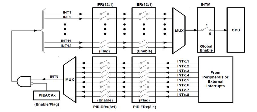
Processes 2021, 9, 358                                                                                         4 of 21

                         as the main body, and a TMS320F2808 chip; motor drive circuit, and proximity switch as
                         the control.

                         2.1.2. Mowing System
                              The mowing system used the action of simulating human mowing as the main axis of
                         research. The mowing range was not limited to a point but achieved maximum efficiency
                         through swinging to the left and right. The mowing pole and the blade were the main
                         body, the TMS320F2808 chip and motor drive circuit were taken as the control, and a
                         slide platform device was designed for swinging to the left and right. The steering device
                         assisted in steering, and the bearing support frame fixed the inclined mowing pole.

                         2.1.3. Human-Machine System
                               The Python built-in program Tkinter was used as the human-machine interface. This
                         interface was used to simulate the brain, the actions to be taken were determined by
                         this interface, as the brain determined and executed. The Raspberry Pi functioned in the
                         interface operation and image recognition was through Virtual Network Computing (VNC)
                         and mobile phone connection. Image recognition simulated human eyes, and three modes
                         and an emergency stop button were designed.

                         2.2. Control Theory
                              A DSP TMS320F2808 chip was ised as the control core, and the program was written
                         to control the motor. The motor drive circuit board was designed with a full-bridge dc-dc
                         converter to control the breakover and cut-off of the four transistors in the way of the
                         gate drive to control the positive and negative rotation of the motor. A proximity switch
                         was added beside the gear of the crawler tracks to complete vehicle speed regulation and
                         speed limit control with a closed loop control. The function of image recognition was
                         added, and a Raspberry Pi and webcam were utilized to achieve real-time image return
                         and obstacle recognition. In order to realize swinging from side to side when simulating
                         human mowing, the mowing device design was divided into the bearing support frame,
                         steering device, slide platform device, and reserve protection
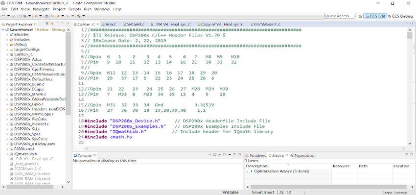
                              In this study, the DSP TMS320F2808 chip developed by Texas Instruments was used
                         as the system control, and Code Composer Studio v6.0 (CCS v6.0) was used as the envi-
                         ronmental interface as shown in Figure 2. C language writing program was used on the
                         platform of F2808 in this development environment.

                         2.2.1. Motor Drive System
                             The motor drive system was one of the main systems of the crawler tracks, and the
                         operating performance of the crawler tracks was determined by its drive system. The
                         drive system consisted of a battery, motor, motor drive circuit board, gear, tracks, and a
                         TMS320F2808 chip. The drive architecture diagram of the crawler tracks is shown in Figure 3.

                         2.2.2. Motor Drive Circuit
                             Full-bridge dc-dc converter was controlled by the pulse width modulation signal
                         outputted by the TMS320F2808 chip. The IC FAN7842 was driven through the gate to
                         amplify the power, a 12 V li-ion battery was used to supply the power, a power MOSFET
                         IRF2807 was used as the switch to control the breakover and cut-off of the four power
                         MOSFETs IRF2807 respectively and to drive the positive and negative rotation of two DC
                         servo motors. The motor drive circuit diagram is shown in Figure 4.
Designing and Manufacturing of Automatic Robotic Lawn Mower
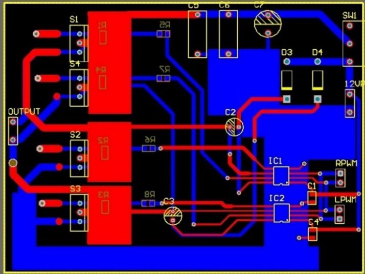
Processes 2021, 9, 358                                                                                                        5 of 21
    Processes 2021, 9, x FOR PEER REVIEW                                                                                   5 of 22

                                   Figure 2. Environmental interface of Code Composer Studio (CCS) v6.0.

                                      2.2.1. Motor Drive System
                                           The motor drive system was one of the main systems of the crawler tracks, and the
                                     operating performance of the crawler tracks was determined by its drive system. The
                                     drive system consisted of a battery, motor, motor drive circuit board, gear, tracks, and a
                                     TMS320F2808 chip. The drive architecture diagram of the crawler tracks is shown in Fig-
                                  Figure
                                     ure2.2.
                                Figure       Environmentalinterface
                                          3.Environmental  interface of
                                                                     of Code
                                                                        Code Composer
                                                                             ComposerStudio
                                                                                      Studio(CCS)
                                                                                             (CCS)v6.0.
                                                                                                   v6.0.

                                     2.2.1. Motor Drive System
                                          The motor drive system was one of the main systems of the crawler tracks, and the
                                     operating performance of the crawler tracks was determined by its drive system. The
                                     drive system consisted of a battery, motor, motor drive circuit board, gear, tracks, and a
                                     TMS320F2808 chip. The drive architecture diagram of the crawler tracks is shown in Fig-
                                     ure 3.

   Processes 2021, 9, x FOR PEER REVIEW                                                                                    6 of 22
                                                  Figure3.3.Motor
                                                 Figure     Motor drive
                                                                  drive system diagram.
                                                                        system diagram.

                                      2.2.2. Motor Drive Circuit
                                           Full-bridge dc-dc converter was controlled by the pulse width modulation signal out-
                                     putted by the TMS320F2808 chip. The IC FAN7842 was driven through the gate to amplify
                                     the power, a 12 V li-ion battery was used to supply the power, a power MOSFET IRF2807
                                     was used as the switch to control the breakover and cut-off of the four power MOSFETs
                                                   Figure 3. Motor
                                     IRF2807 respectively    and todrive
                                                                    drivesystem diagram.and negative rotation of two DC servo mo-
                                                                           the positive
                                     tors. The motor drive circuit diagram is shown in Figure 4.
                                     2.2.2. Motor Drive Circuit
                                           Full-bridge dc-dc converter was controlled by the pulse width modulation signal out-
                                     putted by the TMS320F2808 chip. The IC FAN7842 was driven through the gate to amplify
                                     the power, a 12 V li-ion battery was used to supply the power, a power MOSFET IRF2807
                                     was used as the switch to control the breakover and cut-off of the four power MOSFETs
                                     IRF2807 respectively and to drive the positive and negative rotation of two DC servo mo-
                                     tors. The motor drive circuit diagram is shown in Figure 4.

                                                   Figure4.
                                                  Figure  4. Motor
                                                             Motor drive
                                                                   drive circuit
                                                                         circuitdiagram.
                                                                                 diagram.

                                     2.2.3. Motor Drive Circuit Design and Entity Diagram
                                          In this study, for the drawing of motor drive circuits and preparation of the PCB
                                     (Printed Circuit Board), Altium Designer 15 was used for the circuit design and wiring
                                     operation. The PCB layout of the motor drive circuit is shown in Figure 5.
Designing and Manufacturing of Automatic Robotic Lawn Mower
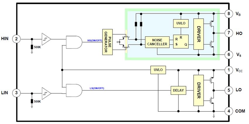
Processes 2021, 9, 358                                                                                              6 of 21

                                        Figure 4. Motor drive circuit diagram.

                          2.2.3.Motor
                         2.2.3. MotorDrive
                                      DriveCircuit
                                           CircuitDesign
                                                   Designand
                                                          andEntity
                                                              EntityDiagram
                                                                    Diagram
                              In
                               Inthis
                                  thisstudy,
                                       study,for
                                              forthe
                                                  thedrawing
                                                      drawingofofmotor
                                                                  motordrive
                                                                        drivecircuits
                                                                                circuitsand
                                                                                          andpreparation
                                                                                               preparationofofthe
                                                                                                               thePCB
                                                                                                                   PCB
                         (Printed  Circuit Board), Altium  Designer 15 was  used    for the circuit design and
                          (Printed Circuit Board), Altium Designer 15 was used for the circuit design and wiringwiring
                         operation.
                          operation.The
                                      ThePCB
                                           PCBlayout
                                               layoutof
                                                      ofthe
                                                         themotor
                                                            motordrive
                                                                  drivecircuit
                                                                        circuitisisshown
                                                                                    shownininFigure
                                                                                               Figure5.5.

                          Figure5.5.PCB
                         Figure      PCB(Printed
                                         (PrintedCircuit
                                                  CircuitBoard)
                                                          Board)layout
                                                                 layoutofofthe
                                                                            themotor
                                                                                motordrive
                                                                                      drivecircuit.
                                                                                            circuit.

                         2.2.4. Gat Driver—IC FAN7842
                              Since the control signal outputted by the TMS320F2808 chip was insufficient to drive
                         the power MOSFET of the motor drive circuit, it was necessary to increase the voltage and
                         current level of the digital control signal through the gate to the drive IC so as to achieve the
                         purpose of driving the power MOSFET. In addition, the signal couild be isolated to avoid
                         interference with each other. The gate drove the IC FAN7842, which had two channels
                         and could drive two MOSFETs, the input end was equipped with over-current protection
                         and a delay transfer circuit to avoid the short circuit problem caused by the simultaneous
                         breakover of the external upper and lower arm switch elements; the high-side channel
                         was equipped with a quasi-level converter circuit, a common mode denoise circuit and
                         a SR latch to suppress EMI (Electromagnetic Interference), RF noise and common-mode
                         transients, so as to avoid data transmission failure caused by the circuit operation near
                         the large motor, and to prevent the high-side quasi-level converter circuit from failure due
                         to current absorption when the main switch was on; the two output ends were provided
                         with two complementary switching elements, the output ends gave instructions to operate
                         the DRIVER control, when the upper arm switch element was on, the signal would be
                         outputted from the output end; in addition, both channels were equipped with UVLO,
                         so when supply voltage VCC (Volt Current Condenser) and floating voltage VBS (Visual
                         Basic Script) levels were lower than the critical values, the power supply could be cut off
                         directly to protect the IC internal integrated circuit. Since the power supply range of the IC
                         VCC and VBS was from 10 V to 20 V, it was in line with the purposes of this study, and the
                         propagation delay was less than 50 ns. The IC system diagram of this study’s adopted IC
                         FAN7842 driven by the described gate is shown in Figure 6.
Designing and Manufacturing of Automatic Robotic Lawn Mower
would be outputted from the output end; in addition, both channels were equipped with
                                   UVLO, so when supply voltage VCC (Volt Current Condenser) and floating voltage VBS
                                   (Visual Basic Script) levels were lower than the critical values, the power supply could be
                                   cut off directly to protect the IC internal integrated circuit. Since the power supply range
Processes 2021, 9, 358
                                   of the IC VCC and VBS was from 10 V to 20 V, it was in line with the purposes of         this
                                                                                                                         7 of 21
                                   study, and the propagation delay was less than 50 ns. The IC system diagram of this
                                   study’s adopted IC FAN7842 driven by the described gate is shown in Figure 6.

                                            Figure6.6.System
                                           Figure      Systemofofthe
                                                                  thegate
                                                                      gatedriver
                                                                           driverIC
                                                                                  ICFAN7842.
                                                                                     FAN7842.

                                   2.2.5.Motor
                                  2.2.5. MotorDrive
                                               DriveCircuit
                                                    CircuitProcess
                                                            Processand
                                                                    andControl
                                                                        ControlMode
                                                                               Mode
                                         TheTMS320F2808
                                        The   TMS320F2808 chipchipwaswasused
                                                                          usedas asthe
                                                                                     thecontrol
                                                                                         controlcore,
                                                                                                  core,and
                                                                                                        andthetheCCS
                                                                                                                  CCSwaswasused
                                                                                                                             usedforforCC
                                    languagedesign
                                   language    designprogramming.
                                                       programming. The  The 3.3
                                                                               3.3VVPWM
                                                                                      PWM(Pulse-Width
                                                                                             (Pulse-WidthModulation)
                                                                                                             Modulation)output
                                                                                                                            outputwas was
                                    outputtedfrom
                                   outputted    fromthe
                                                      the TMS320F2808
                                                        TMS320F2808         chip,
                                                                         chip,     after
                                                                               after     power
                                                                                      power       amplification,
                                                                                             amplification,       the bootstrap
                                                                                                             the bootstrap  circuitcircuit
                                                                                                                                     was
                                   used  to generate
                                    was used          the ICthe
                                               to generate   FAN7842
                                                                IC FAN7842powerpower
                                                                                   supply   12 V driven
                                                                                         supply           by theby
                                                                                                  12 V driven    gate,
                                                                                                                    the the upper
                                                                                                                        gate,       arm
                                                                                                                              the upper
                                   and
Processes 2021, 9, x FOR PEER REVIEWarmthe
                                         andlower  arm composed
                                              the lower             of power
                                                         arm composed          MOSFET
                                                                           of power        IRF2807
                                                                                       MOSFET       was controlled
                                                                                                  IRF2807            by the full-bridge
                                                                                                           was controlled    by the
                                                                                                                                  8 offull-
                                                                                                                                        22
                                   dc-dc
                                    bridgeconverter  to achieve
                                            dc-dc converter      the positive
                                                             to achieve          and negative
                                                                          the positive           rotation
                                                                                         and negative     of the DC
                                                                                                        rotation      motor.
                                                                                                                 of the       The gate
                                                                                                                         DC motor.     The
                                   drive architecture
                                    gate drive         diagram
                                                architecture     is shown
                                                             diagram         in Figure
                                                                        is shown        7.
                                                                                    in Figure  7.

                                                Figure 7. Gate driver control diagram.
                                                Figure 7. Gate driver control diagram.

                                  2.2.6. Bootstrap Circuit
                                  2.2.6. Bootstrap Circuit
                                        In order to obtain sufficient current output, the bootstrap circuit was used in the
                                       In order to obtain sufficient current output, the bootstrap circuit was used in the mo-
                                  motor drive circuit to simplify the circuit and to reduce the costs in this study. When the
                                  tor drive circuit to simplify the circuit and to reduce the costs in this study. When the VBS
                                  VBS voltage of the IC was lower than VCC, the VCC power supply enabled the bootstrap
                                  voltage of the IC was lower than VCC, the VCC power supply enabled the bootstrap ca-
                                  capacitor to be charged through the bootstrap diode to the bootstrap capacitor, the IC
                                  pacitor to be charged through the bootstrap diode to the bootstrap capacitor, the IC low-
                                  low-side channel output end upper arm switch element switched into breakover, and the
                                  side channel output end upper arm switch element switched into breakover, and the drive
                                  drive current was outputted so that power MOSFET was on. When the VBS voltage of
                                  current was outputted so that power MOSFET was on. When the VBS voltage of the IC
                                  the IC was higher than the VCC, the bootstrap diode was in reverse bias position at this
                                  was higher than the VCC, the bootstrap diode was in reverse bias position at this time, the
                                  IC low-side channel output end upper arm switch element switched into cut-off, instead,
                                  the high-side channel output end upper arm switch switched into breakover, and the out-
                                  put drive current made the high-side power MOSFET switch into breakover. In addition,
                                  the breakover of the power switch at the gate-source end due to electrostatic effect hads
Designing and Manufacturing of Automatic Robotic Lawn Mower
Processes 2021, 9, 358                                                                                           8 of 21

                         time, the IC low-side channel output end upper arm switch element switched into cut-off,
                         instead, the high-side channel output end upper arm switch switched into breakover, and
                         the output drive current made the high-side power MOSFET switch into breakover. In
                         addition, the breakover of the power switch at the gate-source end due to electrostatic
                         effect hads to be prevented, as it can result in a short circuit of the upper and lower arm
                         power switch, discharge resistance in the gate and source of the lower arm power switch
                         was used, so that the electrostatic charge had a discharge path.

                         2.2.7. Full-Bridge dc-dc Converter
                               The DC servo motor drive could be divided into three drive modes, single-, two- and
                         four-quadrant, according to load voltage and load current polarity. When working in the
                         first quadrant, the load voltage and load current were all positive, the motor only had
                         the drive capability of positive rotation. If there was a braking demand, only mechanical
                         braking could be relied on, and servo performance requirements could not be achieved.
                         When working in the first and second quadrants, the load voltage was positive and the load
                         current could be positive or negative. At this time, the motor had a positive rotation drive
                         and braking ability. The use of return braking by the motor could increase the dynamic
                         response and improve motor drive efficiency, and the motor servo performance could be
                         greatly improved. If positive rotation, negative rotation, driving, and braking capability
                         were required at the same time, it must work in the four-quadrant driving mode, at this
                         time, the load voltage could be positive or negative, and the load current could also be
                         positive or negative. This study hoped that the drive requirements of maneuverability,
                         accuracy, and high efficiency could be achieved, therefore, the H-bridge circuit of the
                         four-quadrant driving mode was adopted.
                               The four-quadrant DC servo motor drive circuit was developed in this study. Since
                         the drive power supply was supplied by a 12 V li-ion battery at low voltage, the power
                         switch selected power MOSFET, which was suitable for application in a low-voltage field
                         and had the advantages of high switching frequency and low breakover and voltage drop.

                         2.3. Vehicle Position Detection and Speed Measuring Device
                              To enable crawler tracks to move accurately to the target position and to control the
                         speed, an induction-type proximity switch and fixing device of the induction-type proxim-
                         ity switch were installed beside the left and right sides of the gears of the crawler tracks.
                         The function of the sensing the gear was used to feedback the signal to the TMS320F2808
                         chip, the feedback signal and command were compared with CCS programming, the
                         vehicle position control was completed, and the time of receiving the feedback signal each
                         time is calculated so that the purpose of speed regulation and speed limit was achieved.
                         In addition, this design caould also be used as over-current protection. If no feedback
                         signal was received within a period of time, it would mean that the motor could not
                         drive the crawler tracks. At this time, the TMS320F2808 chip would immediately stop the
                         output of the PWM signal to avoid damage of the circuit board components caused by
                         excessive current.

                         2.4. Mowing Device System Architecture
                               Different from automatic lawn mowers on the market, our design placed the mowing
                         cutter head in front of the crawler tracks, which stressed the swinging personification to the
                         left and right, and used the bearing support frame as the human body, the steering device
                         as the human waist, the slide platform device as the human hands, and the synchronization
                         with the motor control and the sensor realized the swinging of the mowing pole to the left
                         and right producing a design to improve the efficiency, save time and human labor cost.

                         2.4.1. Warm Body Sensor
                              A warm body sensor is a passive infrared device, the sensor itself will not emit
                         infrared beams, but it uses the infrared change of the human body to sense the movement
Designing and Manufacturing of Automatic Robotic Lawn Mower
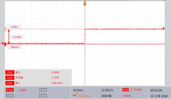
Processes 2021, 9, 358                                                                                                           9 of 21

                                of objects. The infrared module was installed above the support frame. In order to avoid
                                contact between the mowing blade and hard objects, which may cause the blade to break
                                and fly away, or even damage the motor, a blade protection disc was installed above the
                                mowing motor.

                                2.4.2. Mowing Device Power Supply System
                                        The power supply system block diagram of the mowing device is shown in Figure 8.
                                   The power supply mode could be divided into the motor drive circuit board, lawn mower
                                   motor, and relay. The specification of a 12 V 30 A was obtained from two li-ion batteries
                                   in parallel to supply the three motor drive circuit boards and buck-boost. The buck-boost
                                   transforms from a 12 V to 5 V for supply to the DSP control panel, the specification of
                                   33.3 V 45 A was obtained from nine li-ion batteries in three series and three parallels for
                                   supply to the mowing motor so that the robot could autonomously start the mowing blade
                                   and connect with the relay circuit. The relay was L901-12D, one 12 V li-ion battery supplied
Processes 2021, 9, x FOR PEER REVIEW                                                                                     10 of 22
                                   power to the relay, the TMS320F2808 chip output the signal to make the breakover of the
                                   transistor to control the start of the mowing blade.

                               Figure 8.
                               Figure    Mowingdevice
                                      8. Mowing device power
                                                       power supply
                                                             supply system.
                                                                    system.

                                3. Human-Machine Interface and Machine Vision Theory and Application
                               3. Human-Machine Interface and Machine Vision Theory and Application
                                     The human-machine interface used to control the lawn mower in this study was made
                                     The the
                                by using  human-machine     interface
                                              Python built-in  Tkinter, used  to control
                                                                        and modes    werethe  lawn mower
                                                                                          designed            in this for
                                                                                                    on its interface   study   was
                                                                                                                           users  to
                               made    by using the Python   built-in Tkinter,  and  modes  were  designed   on  its interface
                                choose. There were three kinds of selectable modes, including slow mode, inching mode,          for
                               users  to choose.
                                and obstacle     There were
                                               avoidance     threeImage
                                                          mode.     kinds of selectable modes,
                                                                           recognition          including
                                                                                        technology          slowin
                                                                                                     was used     mode,    inching
                                                                                                                     the obstacle
                               mode,    and mode,
                                avoidance   obstacle
                                                  andavoidance
                                                       the methodmode.   Image
                                                                    of frame      recognition
                                                                              subtract        technology
                                                                                       was used            was
                                                                                                 to identify     used in
                                                                                                              whether    thethe ob-
                                                                                                                              object
                               stacle  avoidance  mode,  and   the method
                                ahead could be distinguished as an obstacle. of frame  subtract was  used   to identify   whether
                               the object ahead could be distinguished as an obstacle.
                                3.1. Human-Machine Interface
                               3.1. Human-Machine    Interface
                                     Tkinter, a built-in program using programming Python language was used as the
                                     Tkinter, a built-in
                                human-machine             program
                                                  interface,       usingPiprogramming
                                                             a Raspberry                Pythontolanguage
                                                                           was used to connect             was
                                                                                                  the mobile   usedthrough
                                                                                                             phone   as the
                               human-machine       interface,
                                the VNC as the interface      a Raspberry
                                                           operation        Pi was
                                                                     and image     used to connect
                                                                                recognition, and threetomodes
                                                                                                         the mobile
                                                                                                              and anphone
                                                                                                                      emer-
                                gency   stop button  were designed.
                               through the VNC as the interface operation and image recognition, and three modes and
                               an emergency stop button were designed.
                                3.1.1. Programming Language—Python
                               3.1.1. Python
                                      Programming
                                              programLanguage—Python
                                                        was used to write the Raspberry Pi. Python is a widely used inter-
                               preted   language  that
                                     Python program wasis a high-level   programming
                                                              used to write              and universal
                                                                               the Raspberry            language.
                                                                                               Pi. Python  is a widely Python
                                                                                                                          useddesign
                                                                                                                                inter-
                               preted language that is a high-level programming and universal language. Python or
                               philosophy    emphasizes    code    readability and  concise syntax.  Compared      with  C++       Java,
                                                                                                                               design
                               Python    enables developers    to  express ideas  with fewer  codes. Whether   it  is
                               philosophy emphasizes code readability and concise syntax. Compared with C++ or Java,  a small or  large
                               program,
                               Python      the language
                                         enables          triestotoexpress
                                                 developers          make the  structure
                                                                           ideas         of the
                                                                                  with fewer    program
                                                                                              codes.      clear.it is a small or large
                                                                                                     Whether
                               program, the language tries to make the structure of the program clear.
                               3.1.2. Tkinter
                               3.1.2. Tkinter
                                      Tkinteris a Python module, its function is to call Tcl/Tk interface, it is a cross-platform
                                instruction code graphic. Tkinter is not the only way of Python graphic programming
                                     Tkinter is a Python module, its function is to call Tcl/Tk interface, it is a cross-plat-
                               form instruction code graphic. Tkinter is not the only way of Python graphic program-
                               ming but it is a more popular interface. In this study, Tkinter was used to enable the hu-
                               man-machine interface to remotely control the lawn mower body. Four buttons were de-
                               signed in the window after the program was executed, namely Mode 1, Mode 2, Mode 3,
Processes 2021, 9, 358                                                                                          10 of 21

                         but it is a more popular interface. In this study, Tkinter was used to enable the human-
                         machine interface to remotely control the lawn mower body. Four buttons were designed
                         in the window after the program was executed, namely Mode 1, Mode 2, Mode 3, and the
                         emergency stop button.

                         3.1.3. Remote Connection-VNC
                             This study used a remote connection to control the lawn mower body, and the software
                         used by the remote connection was VNC, which is a screen image sharing and remote
                         operation software using RFB protocol. The software could transmit keyboard and mouse
                         movements and real-time screen images to the operator via the network.

                         3.2. Machine Vision System
                              This study used a set of images captured by webcam. To do this, the Webcam was
                         installed at a high place on the vehicle platform. After the Raspberry Pi obtained the front
                         image information from the webcam, the function of the OpenCV function library was used
                         and pictures captured by the previous frame would subtract the current picture to identify
                         whether there was an object ahead. After capturing the object ahead, the system could
                         recognize whether the object area was greater than the set value, if the area recognized was
                         more than the set value, the object ahead would be considered as an obstacle, and obstacle
                         avoidance measures would be taken.

                         3.2.1. Function Library Adopted—OpenCV
                              The image function library used in this study was OpenCV, which is a cross-platform
                         computer vision library that can be used to develop real-time image processing, computer
                         vision, and as a pattern recognition program. OpenCV is written in C++language, its main
                         interface is also C++language, but a large number of C language interfaces are still retained.
                         This function library has a large number of Python, Java, and MATLAB/OCTAVE interfaces.

                         3.2.2. Image Recognition
                              Image recognition replaces the human eyes with a machine for recognition, measure-
                         ment, judgment, and other functions. The image recognition system is widely used in the
                         detection process. In this study, image recognition was used to judge whether there was
                         an obstacle in front. The core of the obstacle’s identification consisted of two procedures,
                         namely averaging fuzzy and thresholding. The functions and purposes of this are described
                         in detail below.
                              (1) Averaging fuzzy
                              Zadeh [28] proposed that fuzzy is a tool to convert fuzzy concepts that cannot be
                         clearly expressed into quantitative expression, especially in the fuzzy characteristics of
                         human speech expression, which has a good effect. The fuzzy theory has been applied
                         to the management of medication for chronic patients [29], quality assessment of UAV
                         photography services [30], as a rice transplanter control system [31], for aviation accident
                         prevention and management [32], and in urban environmental risk assessment [33], which
                         has made brilliant achievements in practice and academic research.
                              OpenCV provides four fuzzy methods, which can be divided into averaging fuzzy,
                         Gaussian fuzzy, median fuzzy, and bilateral fuzzy. The averaging fuzzy method was
                         adopted in this study. A “blurring” photo is like a defocused photo. When taking photos,
                         people generally do not want to have such a result, however, this feature is very helpful
                         to the algorithm in this study. The thresholding algorithm was used for image cutting,
                         interception, edge detection, and contour search, which all need first the fuzzy processing
                         of photos before it can be effectively carried out.
                              Averaging fuzzy is the simplest method of fuzzification. Firstly, this study selected
                         a total pixel number as an odd number, within a square window of K*K size, the whole
                         picture was scanned from left to right, from top to bottom, the point in the exact center
                         of each window was adjusted to be the average value of all other points in the window,
Processes 2021, 9, 358                                                                                         11 of 21

                         so after the K*K window scans the whole picture, the average fuzzification of the whole
                         picture was complete.
                              (2) Thresholding test
                              In image processing, in order to conveniently and clearly confirm whether it is an
                         obstacle, or to reduce the dimension of images, in this study, a color picture was converted
                         to gray-scale and then to black and white for processing. At this time, the value of any
                         point on this picture was 0 or 255. To determine that the point was black (0) or white (255),
                         a threshold value was set to tell the computer if this value was exceeded, the point would
                         be set to 255 or otherwise 0 after the computer completed the comparison of all points on
                         the picture based on this value, the whole picture would then be converted into a black
                         and white picture. Such a method of processing is called thresholding. In this study, the
                         threshold value was determined according to the obstacles obtained in the picture.

                         4. Program Development and Process Introduction
                              The program development of the robotic lawn mower was designed by using CCS
                         to write C language, a TMS320F2808 chip communicated with the Raspberry Pi through
                         the RS-232 communication protocol, and a human-machine interface was added at the
                         Raspberry Pi end. When the length and width of the rectangular range to be mowed were
                         inputted, the Raspberry Pi transmitted the packet to the TMS320F2808 chip, corresponding
                         actions were implemented through the peripheral interrupt instruction and custom flags,
                         with each system process being introduced as follows one by one.

                         4.1. Process Architecture of DSP System Program
                              In order to realize the functions required by the user, each function of the DSP chip
                         had a corresponding module and peripheral program, such as the GPIO module and
                         EPWM module used in this study. Since each peripheral program will make one or more
                         peripheral interrupt instruction(s) when a triggering event occurs, the CPU cannot process
                         too many external interrupts in real-time, therefore, the Peripheral Interrupt Expansion
                         (PIE) module was required.
                              The multiplexing interrupts diagram of the PIE module is shown in Figure 9. The PIE
                         module of the TMS320F2808 chip could support up to 96 peripheral interrupt instructions,
                         which could be divided into 8 groups (INTx.1~INTx.8), then further divided into 12 sources
                         (INT1~INT12), and Global was set overall to enable the switch of the peripheral interrupt
                         instruction. When the peripheral interrupt flag was enabled, the interrupt service program
                         was called, after completion of the operation, the program counter was reset, Source
                         and Group flags were eliminated, and acknowledgment was made, when an event was
                         triggered, the program would run again.
                              When the program started to run, the system would eliminate the Source and Group
                         interrupt flags in all PIE modules and vector tables to avoid misoperation. Then make the
                         input and output arrangement of the GPIO, after the completion, make Global Enable enter
                         the main program. The main program includes the background program for processing
                         non-real-time events and the interrupt service program for processing real-time events.
                         After the completion of the main program implementation, the reset will enable again.

                         4.2. Control Process of Crawler Tracks
                              When the TMS320F2808 chip received the packet sent from the Raspberry Pi end, the
                         data in the packet was processed; the distance inputted was converted to the number of
                         moving steps, then the crawler tracks move. To make a comparison of the number of steps
                         to be moved and the feedback signal of the proximity switch through the subprogram of
                         the proximity switch, when the two were the same, the crawler tracks immediately stopped,
                         which indicated that the action had been completed, and it would continue to wait for the
                         next packet. The flow chart of the moving subprogram of the crawler tracks is shown in
                         Figure 10.
module of the TMS320F2808 chip could support up to 96 peripheral interrupt instructions,
                                      which could be divided into 8 groups (INTx.1~INTx.8), then further divided into 12
                                      sources (INT1~INT12), and Global was set overall to enable the switch of the peripheral
                                      interrupt instruction. When the peripheral interrupt flag was enabled, the interrupt ser-
                                      vice program was called, after completion of the operation, the program counter was reset,
Processes 2021, 9, 358                                                                                                  12 of 21
                                      Source and Group flags were eliminated, and acknowledgment was made, when an event
                                      was triggered, the program would run again.

Processes 2021, 9, x FOR PEER REVIEW                                                                                       13 of 22

                                     4.2. Control Process of Crawler Tracks
                                            When the TMS320F2808 chip received the packet sent from the Raspberry Pi end, the
                                       data in the packet was processed; the distance inputted was converted to the number of
                                       moving steps, then the crawler tracks move. To make a comparison of the number of steps
                                       to be moved and the feedback signal of the proximity switch through the subprogram of
                                       the proximity switch, when the two were the same, the crawler tracks immediately
                                       stopped, which indicated that the action had been completed, and it would continue to
                                       wait for the next packet. The flow chart of the moving subprogram of the crawler tracks
                                       is shown in Figure 10.
                         Figure 9. Interrupt multiplexing diagram of the Peripheral Interrupt Expansion (PIE) module.
                         Figure 9. Interrupt multiplexing diagram of the Peripheral Interrupt Expansion (PIE) module.

                                           When the program started to run, the system would eliminate the Source and Group
                                      interrupt flags in all PIE modules and vector tables to avoid misoperation. Then make the
                                      input and output arrangement of the GPIO, after the completion, make Global Enable en-
                                      ter the main program. The main program includes the background program for pro-
                                      cessing non-real-time events and the interrupt service program for processing real-time
                                      events. After the completion of the main program implementation, the reset will enable
                                      again.

                                     Figure 10. The flow chart of the moving subprogram of the crawler tracks.
                                     Figure 10. The flow chart of the moving subprogram of the crawler tracks.
                                     4.3. Control Process of the Mowing System
                                     4.3. Control Process
                                           The main   bodyof the Mowing
                                                              of the mowingSystem
                                                                                system was the mowing device. The optocoupler
                                     switchThewas
                                                main  body
                                                   used       of the the
                                                        to receive    mowing
                                                                          signalsystem
                                                                                 and thewas
                                                                                         DSPthe mowing device.
                                                                                              TMS320F2808  chip The
                                                                                                                 was optocoupler
                                                                                                                      sent back to
                                     switch
                                     controlwas   used to receive
                                              the negative   rotationthe
                                                                       of signal and the
                                                                          the motor. WhenDSP  TMS320F2808
                                                                                            the DC motor ofchip  was sentsteering
                                                                                                            the auxiliary  back to
                                     control the negative rotation of the motor. When the DC motor of the auxiliary steering
                                     started, the motor executed the right rotation, and when the left optocoupler switch was
                                     interrupted, the motor executed the left rotation. Similarly, when the right optocoupler
                                     switch was interrupted, the motor executed the right rotation until the instruction was
                                     completed. The reserve protection process was designed so that when the optocoupler
Processes 2021, 9, 358                                                                                                                        13 of 21

                                   started, the motor executed the right rotation, and when the left optocoupler switch was
                                   interrupted, the motor executed the left rotation. Similarly, when the right optocoupler
                                   switch was interrupted, the motor executed the right rotation until the instruction was
                                   completed. The reserve protection process was designed so that when the optocoupler
                                   switch does not send back the signal within six seconds, it was considered a hardware
Processes 2021, 9, x FOR PEER REVIEW                                                                                 14 of 22
                                   failure to stop the blade and steering motor. The mowing system flow chart is shown in
                                   Figure 11.

                               Figure 11. Control process of the mowing system.
                               Figure 11. Control process of the mowing system.
                                4.4. Communication Process
                               4.4. Communication Process
                                      The communication protocol adopted in this study was RS-232. In the RS-232 standard,
                                     The communication
                                characters    were transmitted   protocol
                                                                     one byadopted
                                                                              one through in thisa study
                                                                                                    sequencewasofRS-232.     In theThe
                                                                                                                   bit strings.       RS-232    stand-
                                                                                                                                         advantages
                               ard,  characters     were   transmitted     one     by   one  through      a  sequence
                                were fewer transmission lines, simple wiring, and relatively long transmission distance, of   bit strings.   The   ad-
                               vantages
                                which was   were   fewerfor
                                               suitable    transmission      lines, simple
                                                               data transmission         between wiring,    and relatively chip
                                                                                                      the TMS320F2808          long andtransmission
                                                                                                                                           the Rasp-
                               distance,
                                berry Pi. which      was suitable
                                            The system                for dataand
                                                            first initialized      transmission
                                                                                        entered thebetween
                                                                                                        waiting the
                                                                                                                  line,TMS320F2808
                                                                                                                         the TMS320F2808   chip chip
                                                                                                                                                   and
                               the
                                thenRaspberry        Pi. The
                                       sends the initial     codesystem
                                                                    (0xFC),first     initialized
                                                                              determines              and the
                                                                                                whether      entered    the waiting
                                                                                                                 Raspberry                 line, the
                                                                                                                                Pi was connected
                               TMS320F2808
                                successfully, and chipifthen
                                                          the sends    the initial
                                                                Raspberry     Pi sends codeback
                                                                                              (0xFC),
                                                                                                    the determines
                                                                                                          same value,whether
                                                                                                                           it meant  the  Raspberry
                                                                                                                                        that  the line
                               Pi
                                connection was successful, re-sending a receiving code (0xFE) meant that it allowed meant
                                   was   connected    successfully,    and   if  the Raspberry       Pi sends   back  the   same    value,  it  receipt
                               that  the
                                of the    line connection
                                        packet.   The Raspberry was Pi
                                                                     successful,      re-sending
                                                                        sends a packet,               a receiving code
                                                                                               the TMS320F2808       chip (0xFE)
                                                                                                                             would havemeanta packet
                                                                                                                                                that it
                               allowed
                                with the receipt    of entering
                                           size of six  the packet.the The
                                                                        stageRaspberry
                                                                                of receiving,  Pi receiving
                                                                                                   sends a packet,
                                                                                                               the startthe
                                                                                                                          codeTMS320F2808
                                                                                                                                 (0xFF) meantchip  that
                               would     havewas
                                the packet      a packet
                                                    placed with   thefirst
                                                              in the  size position
                                                                            of six entering      the stage
                                                                                         of the array         of beginning
                                                                                                          at the receiving, receiving        the start
                                                                                                                                of the packet.     The
                                fifth code
                               code   (0xFF) of meant
                                                the packet
                                                        thatwasthe the  addition
                                                                    packet           of the 2nd,
                                                                             was placed        in the3rd,  andposition
                                                                                                        first   4th codes.    If anarray
                                                                                                                         of the      erroratoccurred,
                                                                                                                                               the be-
                                the errorofwould
                               ginning                be displayed,
                                              the packet.    The fifth and
                                                                         codethe     waiting
                                                                                  of the   packetstage
                                                                                                     waswasthe entered.
                                                                                                                addition If  ofthe
                                                                                                                                thepacket
                                                                                                                                      2nd, 3rd,hadand
                                                                                                                                                    no
                                error,  the end   code  (0xFD)    would    be   received.    The   flow   chart  of the
                               4th codes. If an error occurred, the error would be displayed, and the waiting stage was  RS-232    communication
                                protocolIfisthe
                               entered.       shown    in Figure
                                                  packet   had no 12.error, the end code (0xFD) would be received. The flow chart
                               of the RS-232 communication protocol is shown in Figure 12.
Processes 2021, 9, x FOR PEER REVIEW                                                                                                          15 of 22
Processes
 Processes2021,
           2021,9,9,x358
                      FOR PEER REVIEW                                                                                                          1514ofof2221

                                  Figure 12. The flow chart of RS-232 communication protocol.
                                    Figure12.
                                  Figure       Theflow
                                           12.The   flowchart
                                                         chartofofRS-232
                                                                   RS-232communication
                                                                          communicationprotocol.
                                                                                        protocol.
                                  4.5.
                                     4.5.Image
                                            ImageRecognition
                                                    RecognitionProcess
                                                                    Process
                                   4.5. Image
                                          InInthisRecognition    Process
                                                thisstudy,
                                                     study,aawebcam
                                                                webcam was   was used   to capture
                                                                                  used to   capture images,
                                                                                                      images,andandaaRaspberry
                                                                                                                         RaspberryPiPiwas was    used
                                                                                                                                              used   for
                                  for      In
                                        image  this study,  a
                                                 recognition.   webcam
                                                                  If   no    was  used
                                                                           obstacle was  to capture
                                                                                         recognized,   images,
                                                                                                        the      and
                                                                                                             packet    a Raspberry
                                                                                                                      would
                                     image recognition. If no obstacle was recognized, the packet would not be returned. If   not   be Pi was
                                                                                                                                       returned.  used
                                                                                                                                                    If
                                   for
                                  there  image
                                     there  was
                                             wasanrecognition.
                                                   anobstacle,
                                                       obstacle,theIfthe
                                                                       nocaptured
                                                                           obstacleimage
                                                                          captured  was recognized,
                                                                                    image   would
                                                                                            would be     the packet
                                                                                                     be fuzzy
                                                                                                         fuzzy         wouldthe
                                                                                                                 processed,
                                                                                                                processed,     notpicture
                                                                                                                              the   be returned.
                                                                                                                                    picture   wouldIf
                                                                                                                                           would      be
                                   there
                                  be         was
                                       converted  an  obstacle,
                                                     into           the
                                                          gray-scale,     captured
                                                                            and thenimage
                                                                                     the     would
                                                                                          frame      be   fuzzy
                                                                                                  reduction      processed,
                                                                                                               method    would
                                     converted into gray-scale, and then the frame reduction method would be used to identify  thebepicture
                                                                                                                                     used   to would
                                                                                                                                                iden-
                                   be
                                  tify converted
                                     the the  front
                                           front      into gray-scale,
                                                     object.
                                                  object.  If If
                                                              the the       and then
                                                                        identified
                                                                      identified      thearea
                                                                                    object
                                                                                  object   frame   reduction
                                                                                            areaexceeded
                                                                                                  exceeded      method
                                                                                                              the
                                                                                                            the           would
                                                                                                                   setvalue,
                                                                                                                 set   value,  thebe
                                                                                                                             the      usedinin
                                                                                                                                    object
                                                                                                                                   object    tofront
                                                                                                                                                 iden-is
                                                                                                                                                front
                                   tify
                                  isjudgedthe
                                      judgedas front
                                                 asan object.
                                                    anobstacle.If  the
                                                        obstacle.The     identified
                                                                       Theimage     object
                                                                            imagerecognition area
                                                                                   recognitionflow exceeded
                                                                                                  flowchart    the set
                                                                                                        chartisisshown  value,
                                                                                                                  shownin       the
                                                                                                                           inFigure  object
                                                                                                                              Figure13.13.   in  front
                                   is judged as an obstacle. The image recognition flow chart is shown in Figure 13.

                                    Figure 13. Image recognition process flow chart.
                                  Figure 13. Image recognition process flow chart.
                                  Figure 13. Image recognition process flow chart.
Processes
Processes 2021,
          2021, 9,
                9, x358
                     FOR PEER REVIEW                                                                                                    16
                                                                                                                                        15of
                                                                                                                                           of22
                                                                                                                                             21

                                  4.6. Control Process of the Automatic Robotic Lawn Mower
                                   4.6. Control Process of the Automatic Robotic Lawn Mower
                                        After
                                        Afterthethestart-up
                                                    start-upofofthe
                                                                  thepower
                                                                      powersupply,
                                                                               supply, the
                                                                                       the robotic
                                                                                            robotic lawn
                                                                                                       lawn mower
                                                                                                              mower needs
                                                                                                                        needs toto wait
                                                                                                                                   wait for
                                                                                                                                         for the
                                                                                                                                             the
                                  connection     between   the Raspberry     Pi and the  human-machine          interface,
                                   connection between the Raspberry Pi and the human-machine interface, then the human-     then   the  human-
                                  machine
                                   machine interface    sends the
                                              interface sends   thecommunication
                                                                     communicationpacket,
                                                                                        packet,when
                                                                                                  whenthe  the success
                                                                                                             success  of of
                                                                                                                         thethe  communica-
                                                                                                                              communication
                                  tion
                                   was confirmed, modes could be chosen. Both side lengths of the rectangle werewere
                                        was  confirmed,    modes    could  be  chosen.  Both  side   lengths   of the  rectangle     inputinput
                                                                                                                                            after
                                  after
                                   the blade had started for a few seconds. The crawler tracks and lawn mower operated
                                        the  blade  had  started  for a few  seconds.  The   crawler    tracks  and  lawn   mower      operated
                                  and
                                   and cooperated
                                        cooperatedwithwith the
                                                             the choice
                                                                 choice ofof the
                                                                             the mode
                                                                                 mode toto complete
                                                                                            complete the  the instruction.
                                                                                                              instruction. After
                                                                                                                             After thethe motor
                                                                                                                                          motor
                                  started,
                                   started, the PIR sensor module continuously detected for a warm body. If a warm body
                                            the  PIR  sensor   module    continuously    detected     for  a warm   body.    If a warm     body
                                  was
                                   was detected
                                        detected within
                                                    within 2.4
                                                            2.4 mm of
                                                                    of the
                                                                       the straight
                                                                           straight line,
                                                                                     line, then
                                                                                           then all
                                                                                                  all motors
                                                                                                       motors stopped
                                                                                                                 stopped action,
                                                                                                                            action, the
                                                                                                                                      the mode
                                                                                                                                          mode
                                  would
                                   would need
                                           need toto be
                                                     be re-selected.
                                                        re-selected. The
                                                                       Thecontrol
                                                                            control process
                                                                                    process of of the
                                                                                                   the automatic
                                                                                                        automatic robotic
                                                                                                                     robotic lawn
                                                                                                                               lawn mower
                                                                                                                                       mower isis
                                  shown   in   Figure
                                   shown in Figure 14. 14.

                                  Figure14.
                                  Figure    Controlprocess
                                         14.Control processof
                                                           ofan
                                                              anautomatic
                                                                automatic robotic
                                                                           robotic lawn
                                                                                    lawn mower.
                                                                                         mower.

                                   4.7. Warm Body Sensor
                                  4.7. Warm Body Sensor
                                        The circuit diagram applied to the warm body sensor in this study is shown in Figure 15.
                                        The circuit diagram applied to the warm body sensor in this study is shown in Figure
                                   The module itself had automatic induction. When someone entered the induction range,
                                  15. The module itself had automatic induction. When someone entered the induction
                                   a high potential was inputted; when someone left the induction range, it automatically
                                  range, a high potential was inputted; when someone left the induction range, it automat-
                                   delayed to shut down high potential and output low potential. LED could be used to tell
                                  ically
                                   that adelayed  to shut
                                          human body      down
                                                        had beenhigh  potential
                                                                 detected  in theand  output
                                                                                  front. Afterlow  potential.
                                                                                               testing,       LED could
                                                                                                        the output        be used
                                                                                                                    high-potential
                                  to tell that a human   body had  been  detected  in the front. After  testing, the output
                                   voltage was about 3.3–3.6 V and the low-potential voltage was 0 V. The test waveform     high-
                                                                                                                                is
                                  potential
                                   shown involtage    was about 3.3–3.6 V and the low-potential voltage was 0 V. The test
                                              Figure 16.
                                  waveform is shown in Figure 16.
Processes 2021,
Processes       9, x358
          2021, 9,   FOR PEER REVIEW                                                                                                      16 of
                                                                                                                                          17 of 22
                                                                                                                                                21
Processes 2021, 9, x FOR PEER REVIEW                                                                                                      17 of 22

                                 Figure
                                 Figure 15.
                                        15. The
                                            Thecircuit
                                                circuit diagram
                                                        diagram of
                                                                of aa warm
                                                                      warm body
                                                                           body sensor.
                                                                                sensor.
                                 Figure 15. The circuit diagram of a warm body sensor.

                                                     Figure 16. Output data of PIR.
                                                     Figure 16. Output data of PIR.
                                 4.8. Human-Machine Interface Process
                                 4.8. Human-Machine
                                       Human-Machine Interface
                                                            Interface Process
                                                                       Process
                                       In this study, the human-machine interface was written by using Tkinter, an acces-
                                       In this study,
                                                study,thethehuman-machine
                                                               human-machineinterface
                                                                                   interfacewas
                                                                                              was   written
                                                                                                 written   byby    using
                                                                                                                using      Tkinter,
                                                                                                                        Tkinter,       an acces-
                                                                                                                                  an accessory
                                 sory program of Python, four buttons were made respectively, including Mode 1, 2, 3, and
                                 program
                                 sory        of Python,
                                       program     of Python,fourfour
                                                                   buttons
                                                                       buttonswere  made
                                                                                 were  maderespectively,
                                                                                              respectively, including
                                                                                                               includingModeMode1,1,2,2, 3,3, and
                                 the emergency stop button. Mode 1 and Mode 2 were used to input the mowing area and
                                  the emergency
                                 the  emergencystop  stopbutton.
                                                             button.Mode
                                                                       Mode    1 and
                                                                             1 and     Mode
                                                                                    Mode      2 were
                                                                                           2 were      used
                                                                                                    used        to input
                                                                                                          to input         the mowing
                                                                                                                      the mowing        area area
                                                                                                                                              and
                                 to complete instructions in a bow path. Mode 1 was slow mode: The crawler tracks moved
                                  and
                                 to    to complete
                                    complete           instructions
                                                instructions           in apath.
                                                                 in a bow    bow Mode
                                                                                  path. Mode     1 wasmode:
                                                                                         1 was slow     slow mode:       The crawler
                                                                                                                 The crawler               tracks
                                                                                                                                tracks moved
                                 forward, and the mowing pole would swing to the left and right until the action was com-
                                  moved forward,
                                 forward,              and the mowing
                                             and the mowing        pole wouldpoleswing
                                                                                   wouldto swing
                                                                                           the leftto theright
                                                                                                    and    left and
                                                                                                                  untilright  until the
                                                                                                                        the action    wasaction
                                                                                                                                            com-
                                 pleted. Mode 2 was the inching mode: The crawler tracks would advance for a distance of
                                 was   completed.     Mode     2  was  the  inching   mode:   The  crawler    tracks
                                 pleted. Mode 2 was the inching mode: The crawler tracks would advance for a distance  would    advance      forofa
                                 half a blade, then stop, the mowing pole would swing once, and repeat the operation until
                                  distance   of half  a  blade,   then  stop,  the mowing     pole  would     swing    once,
                                 half a blade, then stop, the mowing pole would swing once, and repeat the operation until     and   repeat    the
                                 the instruction was completed. Mode 3 was the obstacle avoidance mode: The crawler
                                  operation
                                 the          until was
                                      instruction    the instruction
                                                            completed.was Modecompleted.
                                                                                  3 was the Mode   3 wasavoidance
                                                                                               obstacle    the obstacle     avoidance
                                                                                                                         mode:             mode:
                                                                                                                                  The crawler
                                 tracks  movedtracks
                                 The crawler       forward,
                                                          movedmeanwhile
                                                                    forward,the   mowing pole
                                                                               meanwhile           would swing       to the swing
                                                                                                                             left and toright.   If
                                 tracks  moved forward,         meanwhile     the mowing thepolemowing       pole would
                                                                                                   would swing       to the left and      the left
                                                                                                                                         right.  If
                                 the
                                  andwebcam
                                       right. Ifidentified
                                                  the webcam   obstacles   on the
                                                                   identified       way, iton
                                                                                obstacles   would    sendit back
                                                                                               the way,      would  thesend
                                                                                                                         signal
                                                                                                                              backto the
                                                                                                                                     the Rasp-
                                 the  webcam     identified     obstacles  on the   way, it would    send back      the signal    to the signal
                                                                                                                                           Rasp-
                                 berry
                                  to thePi  and then Pi
                                         Raspberry      transmit
                                                           and then thetransmit
                                                                         packet tothe
                                                                                    thepacket
                                                                                        TMS320F2808       chip to command
                                                                                               to the TMS320F2808          chip tothe    crawler
                                                                                                                                    command
                                 berry   Pi and then transmit        the packet to  the TMS320F2808       chip to command          the   crawler
                                 tracks  to perform
                                  the crawler           the
                                                tracksthe    obstacle
                                                          to perform    avoidance
                                                                        the obstacle function.
                                                                                       avoidanceIn case of
                                                                                                    function.hardware      and
                                                                                                                  In caseand    software
                                                                                                                            of hardware       fail-
                                                                                                                                              and
                                 tracks  to perform           obstacle avoidance     function.  In case  of hardware            software fail-
                                 ure,  the
                                  software  emergency
                                             failure,  the stop   button
                                                            emergency      could
                                                                          stop     be
                                                                                buttonused
                                                                                        couldto stop
                                                                                                be    the
                                                                                                    used   crawler
                                                                                                          to  stop     tracks
                                                                                                                     the        and
                                                                                                                          crawler      the
                                                                                                                                    tracks  lawn
                                                                                                                                              and
                                 ure, the emergency stop button could be used to stop the crawler tracks and the lawn
                                 mower motor. The human-machine interface displayed on the mobile phone is shown in
                                 mower motor. The human-machine interface displayed on the mobile phone is shown in
                                 Figure 17.
                                 Figure 17.
You can also read