User Manual L-884 Land and Hold Short Operations (LAHSO) Power Control Unit - 96A0235, Rev. R, 2020/09/01 - ADB Safegate
←
→
Page content transcription
If your browser does not render page correctly, please read the page content below

L-884 Land and Hold Short Operations
(LAHSO) Power Control Unit

User Manual
96A0235, Rev. R, 2020/09/01

A.0 Disclaimer / Standard Warranty
CE certification

The equipment listed as CE certified means that the product complies with the essential requirements concerning safety and
hygiene. The European directives that have been taken into consideration in the design are available on written request to
ADB SAFEGATE.

ETL certification

The equipment listed as ETL certified means that the product complies with the essential requirements concerning safety and
FAA Airfield regulations. The FAA directives that have been taken into consideration in the design are available on written
request to ADB SAFEGATE.

All Products Guarantee

ADB SAFEGATE will correct by repair or replacement per the applicable guarantee above, at its option, equipment or parts
which fail because of mechanical, electrical or physical defects, provided that the goods have been properly handled and
stored prior to installation, properly installed and properly operated after installation, and provided further that Buyer gives
ADB SAFEGATE written notice of such defects after delivery of the goods to Buyer. Refer to the Safety section for more
information on Material Handling Precautions and Storage precautions that must be followed.
ADB SAFEGATE reserves the right to examine goods upon which a claim is made. Said goods must be presented in the same
condition as when the defect therein was discovered. ADB SAFEGATE furthers reserves the right to require the return of such
goods to establish any claim.
ADB SAFEGATE's obligation under this guarantee is limited to making repair or replacement within a reasonable time after
receipt of such written notice and does not include any other costs such as the cost of removal of defective part, installation
of repaired product, labor or consequential damages of any kind, the exclusive remedy being to require such new parts to be
furnished.
ADB SAFEGATE's liability under no circumstances will exceed the contract price of goods claimed to be defective. Any returns
under this guarantee are to be on a transportation charges prepaid basis. For products not manufactured by, but sold by ADB
SAFEGATE, warranty is limited to that extended by the original manufacturer. This is ADB SAFEGATE's sole guarantee and
warranty with respect to the goods; there are no express warranties or warranties of fitness for any particular purpose or any
implied warranties of fitness for any particular purpose or any implied warranties other than those made expressly herein. All
such warranties being expressly disclaimed.

Standard Products Guarantee

Products of ADB SAFEGATE manufacture are guaranteed against mechanical, electrical, and physical defects (excluding lamps)
which may occur during proper and normal use for a period of two years from the date of ex-works delivery, and are
guaranteed to be merchantable and fit for the ordinary purposes for which such products are made.

        Note
        See your sales order contract for a complete warranty description.

FAA Certified product installed in the United States and purchased or funded with monies through the
Airport Improvement Program (AIP) installations guarantee

ADB SAFEGATE L858 Airfield Guidance Signs are warranted against mechanical and physical defects in design or manufacture
for a period of 2 years from date of installation, per FAA AC 150/5345-44 (applicable edition).
ADB SAFEGATE L858(L) Airfield Guidance Signs are warranted against electrical defects in design or manufacture of the LED or
LED specific circuitry for a period of 4 years from date of installation, per FAA EB67 (applicable edition).
ADB SAFEGATE LED light fixtures (with the exception of obstruction lighting) are warranted against electrical defects in design
or manufacture of the LED or LED specific circuitry for a period of 4 years from date of installation, per FAA EB67 (applicable
edition). .

96A0235, Rev. R, 2020/09/01                                                                                                        iii
Copyright © ADB Safegate, All Rights Reserved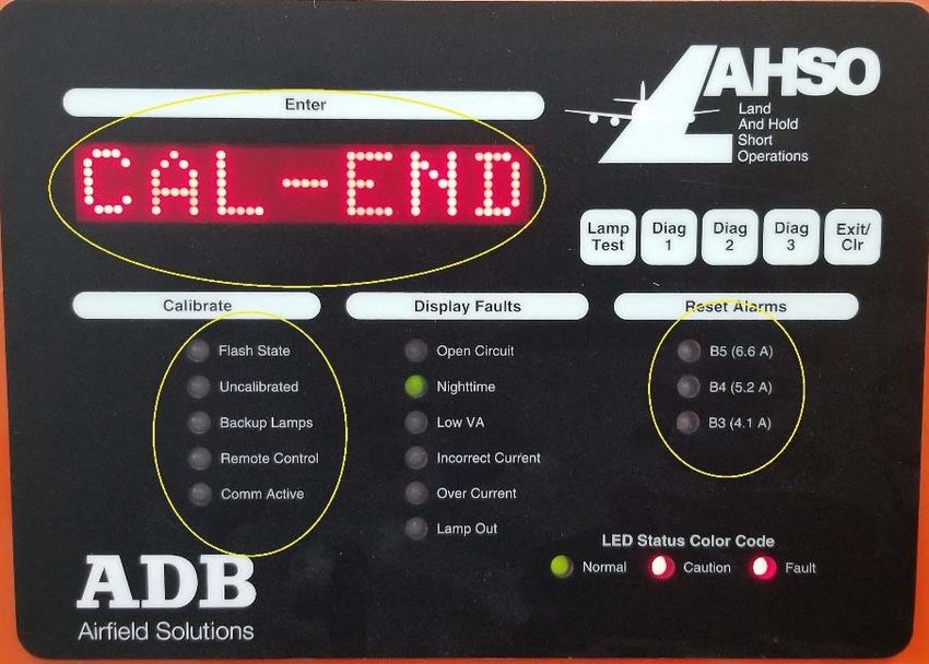
L-884 Land and Hold Short Operations

        Note
        See your sales order contract for a complete warranty description.

Liability

                    WARNING
                    Use of the equipment in ways other than described in the catalog leaflet and the manual may result in personal injury,
                    death, or property and equipment damage. Use this equipment only as described in the manual.

ADB SAFEGATE cannot be held responsible for injuries or damages resulting from non-standard, unintended uses of its
equipment. The equipment is designed and intended only for the purpose described in the manual. Uses not described in the
manual are considered unintended uses and may result in serious personal injury, death or property damage.
Unintended uses, includes the following actions:

• Making changes to equipment that have not been recommended or described in this manual or using parts that are not
    genuine ADB SAFEGATE replacement parts or accessories.
• Failing to make sure that auxiliary equipment complies with approval agency requirements, local codes, and all applicable
    safety standards if not in contradiction with the general rules.
• Using materials or auxiliary equipment that are inappropriate or incompatible with your ADB SAFEGATE equipment.
• Allowing unskilled personnel to perform any task on or with the equipment.
©   ADB SAFEGATE BV

This manual or parts thereof may not be reproduced, stored in a retrieval system, or transmitted, in any form or by any means,
electronic, mechanical, photocopying, recording, nor otherwise, without ADB SAFEGATE BV's prior written consent.
This manual could contain technical inaccuracies or typographical errors. ADB SAFEGATE BV reserves the right to revise this
manual from time to time in the contents thereof without obligation of ADB SAFEGATE BV to notify any person of such
revision or change. Details and values given in this manual are average values and have been compiled with care. They are not
binding, however, and ADB SAFEGATE BV disclaims any liability for damages or detriments suffered as a result of reliance on
the information given herein or the use of products, processes or equipment to which this manual refers. No warranty is made
that the use of the information or of the products, processes or equipment to which this manual refers will not infringe any
third party's patents or rights. The information given does not release the buyer from making their own experiments and
tests.

iv
Copyright © ADB Safegate, All Rights Reserved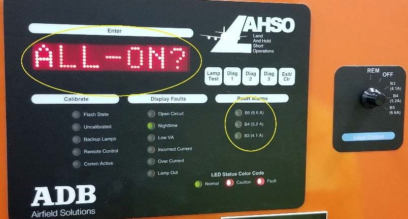
TABLE OF CONTENTS

1.0 Safety ....................................................................................................................................................................................... 1
     1.1 Safety Messages ........................................................................................................................................................................................................ 1
          1.1.1 Introduction to Safety ................................................................................................................................................................................. 2
          1.1.2 Intended Use .................................................................................................................................................................................................. 2
          1.1.3 Material Handling Precautions: Storage .............................................................................................................................................. 3
          1.1.4 Material Handling Precautions: Fasteners .......................................................................................................................................... 3
          1.1.5 Maintenance Safety ..................................................................................................................................................................................... 4
          1.1.6 Material Handling Precautions, ESD ..................................................................................................................................................... 4
          1.1.7 Arc Flash and Electric Shock Hazard ..................................................................................................................................................... 5
2.0 L-884 / LAHSO PCU ................................................................................................................................................................ 7
     2.1 About this manual .................................................................................................................................................................................................... 7
          2.1.1 Introduction .................................................................................................................................................................................................... 7
          2.1.2 How to work with the manual ................................................................................................................................................................. 7
3.0 Product Introduction ............................................................................................................................................................. 9
    3.1 Land and Hold Short Operations Power and Control Unit ....................................................................................................................... 9
    3.2 Equipment Specification Data ........................................................................................................................................................................... 11
         3.2.1 LAHSO Power Control Unit: Required Equipment ........................................................................................................................ 11
         3.2.2 Flashing Operation .................................................................................................................................................................................... 11
         3.2.3 LAHSO Control Panel ............................................................................................................................................................................... 13
         3.2.4 Power Supply for LAHSO Controller ................................................................................................................................................... 13
4.0 Installation ............................................................................................................................................................................ 15
     4.1 Mounting and Wiring the LAHSO Components ........................................................................................................................................ 16
     4.2 Connecting a Remote Control Interface ........................................................................................................................................................ 20
     4.3 FAA Specified Outputs .......................................................................................................................................................................................... 20
     4.4 FAA Specified Inputs ............................................................................................................................................................................................. 20
     4.5 ADB SAFEGATE LAHSO Calibration Procedure ........................................................................................................................................... 21
     4.6 Setting Dip Switches .............................................................................................................................................................................................. 30
     4.7 Turning on LAHSO ................................................................................................................................................................................................. 30
     4.8 LAHSO Output Current Adjustment Procedures ........................................................................................................................................ 30
     4.9 Adjusting Output Current ................................................................................................................................................................................... 31
     4.10 Adjusting Over Current ...................................................................................................................................................................................... 34
5.0 Operation .............................................................................................................................................................................. 35
    5.1 Current Regulation ................................................................................................................................................................................................. 36
    5.2 SCRs ............................................................................................................................................................................................................................. 36
    5.3 Contactor ................................................................................................................................................................................................................... 37
    5.4 Transformers ............................................................................................................................................................................................................. 37
    5.5 On/Off Control ........................................................................................................................................................................................................ 37
    5.6 Current Sensing Relays ......................................................................................................................................................................................... 37
    5.7 PCU Control and Monitoring Systems ........................................................................................................................................................... 37
    5.8 Control System ........................................................................................................................................................................................................ 37
    5.9 Monitoring System ................................................................................................................................................................................................. 38
    5.10 PCU Local Control Panel .................................................................................................................................................................................... 38
    5.11 Touchpad Switches and Indicators ................................................................................................................................................................ 38
    5.12 Rotary Switch ......................................................................................................................................................................................................... 39
    5.13 Current Sensing Relays ...................................................................................................................................................................................... 41
    5.14 Photocells ................................................................................................................................................................................................................ 42
    5.15 Operation Procedure Details ........................................................................................................................................................................... 43
         5.15.1 LAHSO Monitoring Operational Procedures ................................................................................................................................ 43
         5.15.2 Turning On LAHSO .................................................................................................................................................................................. 43
         5.15.3 Checking Power for CCT Board and Lamp Flash ......................................................................................................................... 43
         5.15.4 Checking for Open Circuit, Over Current, Current Out of Range, and Lamps Out ........................................................ 44
         5.15.5 Checking for LAHSO Position Sign Failure .................................................................................................................................... 44
         5.15.6 Checking for Lamp Out ......................................................................................................................................................................... 44

96A0235, Rev. R, 2020/09/01                                                                                                                                                                                                                v
Copyright © ADB Safegate, All Rights Reserved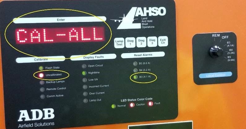
L-884 Land and Hold Short Operations
TABLE OF CONTENTS

                5.15.7 Checking Backup Lamp Out ................................................................................................................................................................ 45
                5.15.8 Automatic Monitoring Lights during Daylight and Darkness ................................................................................................ 45
                5.15.9 Lamp Out Monitoring Calibration Procedures ............................................................................................................................ 46
                5.15.10 LAHSO Operations ............................................................................................................................................................................... 51
6.0 Maintenance ......................................................................................................................................................................... 53
    6.1 Maintenance Schedule ......................................................................................................................................................................................... 53
    6.2 Troubleshooting ...................................................................................................................................................................................................... 54
         6.2.1 Diagnostic Procedures ............................................................................................................................................................................. 56
         6.2.2 LAHSO Bad Photo Cell Detected Time Out Adjustment ............................................................................................................ 58
         6.2.3 Replacing the LAHSO Control PCB 44A5928 .................................................................................................................................. 60
7.0 Wiring Schematics ............................................................................................................................................................... 61
    7.1 LAHSO Internal Wiring Schematic ................................................................................................................................................................... 61
    7.2 LAHSO Internal Wiring Schematic Notes and Options ........................................................................................................................... 63
8.0 LAHSO Parts ......................................................................................................................................................................... 65
     8.1 Spare Parts ................................................................................................................................................................................................................ 67
A.0 SUPPORT .............................................................................................................................................................................. 69
    A.1 ADB SAFEGATE Website ...................................................................................................................................................................................... 69
    A.2 Recycling .................................................................................................................................................................................................................... 69
         A.2.1 Local Authority Recycling ....................................................................................................................................................................... 69
         A.2.2 ADB SAFEGATE Recycling ....................................................................................................................................................................... 70

vi
Copyright © ADB Safegate, All Rights Reserved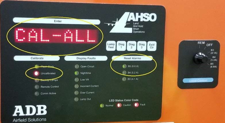
1.0 Safety
Introduction to Safety

This section contains general safety instructions for installing and using ADB SAFEGATE equipment. Some safety instructions
may not apply to the equipment in this manual. Task- and equipment-specific warnings are included in other sections of this
manual where appropriate.

1.1 Safety Messages

HAZARD Icons used in the manual

For all HAZARD symbols in use, see the Safety section. All symbols must comply with ISO and ANSI standards.
Carefully read and observe all safety instructions in this manual, which alert you to safety hazards and conditions that may
result in personal injury, death or property and equipment damage and are accompanied by the symbol shown below.

                    WARNING
                    Failure to observe a warning may result in personal injury, death or equipment damage.

                    DANGER - Risk of electrical shock or ARC FLASH
                    Disconnect equipment from line voltage. Failure to observe this warning may result in personal injury, death, or
                    equipment damage. ARC Flash may cause blindness, severe burns or death.

                    WARNING - Wear personal protective equipment
                    Failure to observe may result in serious injury.

                    WARNING - Do not touch
                    Failure to observe this warning may result in personal injury, death, or equipment damage.

                    CAUTION
                    Failure to observe a caution may result in equipment damage.

Qualified Personnel

                    Important Information
                    The term qualified personnel is defined here as individuals who thoroughly understand the equipment and its safe
                    operation, maintenance and repair. Qualified personnel are physically capable of performing the required tasks, familiar
                    with all relevant safety rules and regulations and have been trained to safely install, operate, maintain and repair the
                    equipment. It is the responsibility of the company operating this equipment to ensure that its personnel meet these
                    requirements.
                    Always use required personal protective equipment (PPE) and follow safe electrical work practice.

96A0235, Rev. R, 2020/09/01                                                                                                                    1
Copyright © ADB Safegate, All Rights Reserved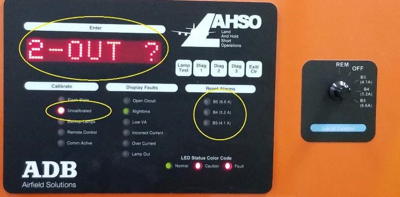
L-884 Land and Hold Short Operations
Safety

1.1.1 Introduction to Safety

                   CAUTION
                   Unsafe Equipment Use
                   This equipment may contain electrostatic devices, hazardous voltages and sharp edges on components
                   •    Read installation instructions in their entirety before starting installation.
                   •    Become familiar with the general safety instructions in this section of the manual before installing,
                        operating, maintaining or repairing this equipment.
                   •    Read and carefully follow the instructions throughout this manual for performing specific tasks and
                        working with specific equipment.
                   •    Make this manual available to personnel installing, operating, maintaining or repairing this
                        equipment.
                   •    Follow all applicable safety procedures required by your company, industry standards and
                        government or other regulatory agencies.
                   •    Install all electrical connections to local code.
                   •    Use only electrical wire of sufficient gauge and insulation to handle the rated current demand. All
                        wiring must meet local codes.
                   •    Route electrical wiring along a protected path. Make sure they will not be damaged by moving
                        equipment.
                   •    Protect components from damage, wear, and harsh environment conditions.
                   •    Allow ample room for maintenance, panel accessibility, and cover removal.
                   •    Protect equipment with safety devices as specified by applicable safety regulations
                   •    If safety devices must be removed for installation, install them immediately after the work is
                        completed and check them for proper functioning prior to returning power to the circuit.

                   Failure to follow this instruction can result in serious injury or equipment damage

Additional Reference Materials

                    Important Information

                    •   IEC - International Standards and Conformity Assessment for all electrical, electronic and related technologies.

                    •   IEC 60364 - Electrical Installations in Buildings.

                    •   FAA Advisory: AC 150/5340-26 (current edition), Maintenance of Airport Visual Aid Facilities.

                    •   Maintenance personnel must refer to the maintenance procedure described in the ICAO Airport Services Manual,
                        Part 9.

                    •   ANSI/NFPA 79, Electrical Standards for Metalworking Machine Tools.

                    •   National and local electrical codes and standards.

1.1.2 Intended Use

                   CAUTION
                   Use this equipment as intended by the manufacturer
                   This equipment is designed to perform a specific function, do not use this equipment for other purposes

                   •    Using this equipment in ways other than described in this manual may result in personal injury, death
                        or property and equipment damage. Use this equipment only as described in this manual.

                   Failure to follow this instruction can result in serious injury or equipment damage

2
Copyright © ADB Safegate, All Rights Reserved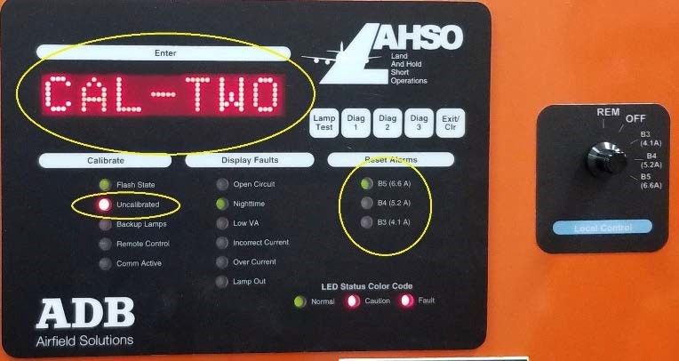
1.1.3 Material Handling Precautions: Storage

                   CAUTION
                   Improper Storage
                   Store this equipment properly
                   •   If equipment is to be stored prior to installation, it must be protected from the weather and kept free
                       of condensation and dust.

                   Failure to follow this instruction can result in equipment damage

1.1.4 Material Handling Precautions: Fasteners

                   DANGER
                   Foreign Object Damage - FOD
                   This equipment may contain fasteners that may come loose - torque properly.

                   •   Only use fasteners of the same type as the one originally supplied with the equipment.
                   •   Use of incorrect combination of gaskets, bolts and nuts can create severe damages to the product
                       installation and create safety risk .
                   •   You need to know what base the light fixture will be installed in, in order to chose the correct gasket,
                       bolts and nuts.
                   •   Bolt type, length, and torque value are determined by type of base, height of spacers used, and clamp
                       force required in FAA Engineering Brief No 83 (latest revision).
                   •   Due to the risk of bolts vibrating loose, do not use any type of washer with the fixing bolts (such as
                       split lock washers) other than an anti-vibration washer. Anti-vibration washers as defined in FAA EB
                       83 (latest edition) must be used. For installations other than FAA, use the base can manufacturer's
                       recommendations.
                   •   Always tighten the fasteners to the recommended torque. Use a calibrated torque wrench and apply
                       the recommended adhesive type.
                   •   Obey the instructions of the adhesives necessary for the fasteners.

                   Failure to follow these warnings may cause the fasteners to loosen, damage the equipment,
                   potentially to loosen the equipment. This can lead to a highly dangerous situation of FOD, with
                   potential lethal consequences.

        Note
        To minimize the risk of errors, the ADB SAFEGATE Sales Representative will have information on which gasket goes
        with which base. This information is also provided in the product Data sheets, the User Manuals and the Spare Part
        Lists.

        CAUTION
        Use of incorrect combination of gaskets, bolts and nuts can create severe damages to the product installation and
        create multiple safety risks.
        To obtain a safe and watertight installation the O-ring and retaining bolt stated in the document must be used.
        You need to know what base the light fixture will be installed in, in order to choose the correct gasket, bolts and nuts.
        Failure to follow these cautions can result in equipment damage or aircraft FOD.

96A0235, Rev. R, 2020/09/01                                                                                                         3
Copyright © ADB Safegate, All Rights Reserved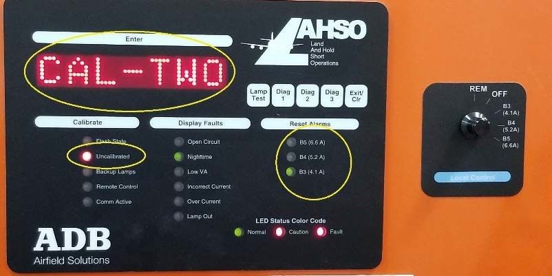
L-884 Land and Hold Short Operations
Safety

1.1.5 Maintenance Safety

                   DANGER
                   Electric Shock Hazard
                   This equipment may contain electrostatic devices
                   •   Do not operate a system that contains malfunctioning components. If a component malfunctions,
                       turn the system OFF immediately.
                   •   Disconnect and lock out electrical power.
                   •   Allow only qualified personnel to make repairs. Repair or replace the malfunctioning component
                       according to instructions provided in its manual.

                   Failure to follow these instructions can result in death or equipment damage

1.1.6 Material Handling Precautions, ESD

                   CAUTION
                   Electrostatic Sensitive Devices
                   This equipment may contain electrostatic devices

                   •   Protect from electrostatic discharge.
                   •   Electronic modules and components should be touched only when this is unavoidable e.g. soldering,
                       replacement.
                   •   Before touching any component of the cabinet you shall bring your body to the same potential as the
                       cabinet by touching a conductive earthed part of the cabinet.
                   •   Electronic modules or components must not be brought in contact with highly insulating materials
                       such as plastic sheets, synthetic fiber clothing. They must be laid down on conductive surfaces.
                   •   The tip of the soldering iron must be grounded.
                   •   Electronic modules and components must be stored and transported in conductive packing.

                   Failure to follow this instruction can result in equipment damage

4
Copyright © ADB Safegate, All Rights Reserved
1.1.7 Arc Flash and Electric Shock Hazard
DANGER
Series Circuits have Hazardous Voltages
This equipment produces high voltages to maintain the specified current - Do NOT Disconnect while
energized.
• Allow only qualified personnel to perform maintenance, troubleshooting, and repair tasks.
• Only persons who are properly trained and familiar with ADB SAFEGATE equipment are permitted to
service this equipment.
• An open airfield current circuit is capable of generating >5000 Vac and may appear OFF to a meter.
• Never unplug a device from a constant current circuit while it is operating; Arc flash may result.
• Disconnect and lock out electrical power.
• Always use safety devices when working on this equipment.
• Follow the recommended maintenance procedures in the product manuals.
• Do not service or adjust any equipment unless another person trained in first aid and CPR is present.
• Connect all disconnected equipment ground cables and wires after servicing equipment. Ground all
conductive equipment.
• Use only approved ADB SAFEGATE replacement parts. Using unapproved parts or making
unapproved modifications to equipment may void agency approvals and create safety hazards.
• Check the interlock systems periodically to ensure their effectiveness.
• Do not attempt to service electrical equipment if standing water is present. Use caution when
servicing electrical equipment in a high-humidity environment.
• Use tools with insulated handles when working with airfield electrical equipment.
Failure to follow these instructions can result in death or equipment damage
96A0235, Rev. R, 2020/09/01 5
Copyright © ADB Safegate, All Rights ReservedL-884 Land and Hold Short Operations Safety 6 Copyright © ADB Safegate, All Rights Reserved
2.0 L-884 / LAHSO PCU
Land and Hold Short Operations (LAHSO) include landing and holding short of an intersecting runway, taxiway,
predetermined runway point and/or an approach/departure flight path. A LAHSO system is controlled by the LAHSO PCU, this
consists of a row of six or seven in-pavement unidirectional pulsing white lights installed across the runway at the hold-short
point.

2.1 About this manual

2.1.1 Introduction
The manual shows the information necessary to:

• Install and maintain the L-884 / LAHSO PCU equipment.

2.1.2 How to work with the manual

 1. Become familiar with the structure and content.
 2. Carry out the actions completely and in the given sequence.

96A0235, Rev. R, 2020/09/01                                                                                                  7
Copyright © ADB Safegate, All Rights Reserved
L-884 Land and Hold Short Operations
L-884 / LAHSO PCU

8
Copyright © ADB Safegate, All Rights Reserved
3.0 Product Introduction
Land and Hold Short Operations (LAHSO) include landing and holding short of an intersecting runway, taxiway,
predetermined runway point and/or an approach/departure flight path. A LAHSO system is controlled by the LAHSO PCU, this
consists of a row of six or seven in-pavement unidirectional pulsing white lights installed across the runway at the hold-short
point.

3.1 Land and Hold Short Operations Power and Control Unit

Uses

A Land and Hold Short Operations (LAHSO) system is used to increase airport capacity. A LAHSO system, controlled by an
L-884 Power and Control Unit (PCU), consists of a row of six or seven in-pavement unidirectional pulsing white lights installed
across the runway at the hold-short point.
For new installations, six lights are used. Seven lights are used if five lights were installed according to AC 150/5345-54. Lights
pulse simultaneously at a rate of 1.72 seconds ON, 0.46 seconds OFF. The fixture may be either clear L-850A or L-850F
(incandescent fixtures only). The L-850F has two lamps, one primary and one backup. If two or more lights in the primary
LAHSO bar have failed, the PCU switches from the primary to the backup lamp bar. See data sheet 2001 (L-850A) or data
sheet 2037 (L-850F) for more information.

PCU Specifications

Input Voltage                            Outdoor unit: 240 VAC, 60 Hz
                                         Indoor unit: 120 VAC, 208 VAC, 240 VAC; 60 Hz

PCU maximum load                         1,600 VA

Distance                                 LAHSO lights may be up to 10,000 ft (3 km) away (20,000 ft/6 km round trip) using AWG 8, L-824
                                         wire

Indoor enclosure                         - NEMA 1
                                         - Style I, -40 °F to +131 °F (40 °C to +55 °C)
                                         - 63 lb (2 8.58 kg)
                                         - 24 × 8.6 3 × 24 in (61 × 22 × 61 cm)

Outdoor enclosure                        - NEMA 4
                                         - Style II, -67 °F to +158 °F (-55 °C to +70 °C)
                                         - 72 lb (3 2.66 kg)
                                         - 24 × 8 × 24 in (61 × 20.3 × 61 cm)

        Note
        Outdoor PCU must be mounted outside airfield safety area. Mounting an outdoor PCU in the vicinity of the LAHSO
        fixtures is the preferred method of installation.

Theory of Operation

LAHSO lights are flashing in-pavement white lights designed to pulse simultaneously so that they are distinguishable from
the various runway lights. The lights pulse from one of the three steps (6.6 A, 5.2 A, or 4.1 A) for 1.72 seconds and then to 1 A
for 0.46 seconds. The pulsing lights provide an effective visual cue for the pilot from short final through the landing rollout,
indicating the point beyond which the landing aircraft is not authorized to proceed. Either six or seven unidirectional clear
L-850A or L-850F lights (without film disc cutouts) are used.
The L-884 PCU consists of a microprocessor-controlled circuit that regulates the output current in a manner similar to an
L-828 constant current regulator.
ON/OFF control is activated from the Air Traffic Control Tower or by a local control switch on the PCU (See Figure 1). If the
PCU local control switch is in the Local position (OFF or B3/B4/B5), then the Field/Tower PCU contact will open, activating a
“Field Control” light on the LAHSO panel. When the PCU local control switch is in the Remote position, the Field/Tower PCU
contact will close, activating a “Tower Control” light on the LAHSO panel.

96A0235, Rev. R, 2020/09/01                                                                                                               9
Copyright © ADB Safegate, All Rights Reserved
L-884 Land and Hold Short Operations
Product Introduction
The PCU photocell defines whether day or night conditions exist. During daytime, the intensity is always set to B5 (6.6 A) even
if the runway edge lights are off. At nighttime, the PCU uses two current sensing relays (mounted separately) to monitor the
intensity of the corresponding HIRL (5-step) or MIRL (3-step) runway edge lighting circuit and to automatically set the
intensity step. Alternately, an L-830 transformer can be used to monitor the runway edge circuit.
A fault alarm is generated if one of the following conditions occurs:
• Failure of the PCU electronics due to failure of the DC power supply (Time Delay = 0 sec)
• Loss of input power to PCU (Time Delay = 0 sec)
• Failure to pulse the lights (Time Delay = 5 sec)
• Two or more lights in a bar have failed (Time Delay = 5 sec)
Figure 1: Figure 1
Mode 2 LAHSO
Control Panel
Power and
Control
Unit
ay
nw
Ru Ru
nw Air Traffic Control Tower
ay
Sign
Airfield Lighting
Vault
6 or 7 L-850 or L850F
clear in-pavement lights
The PCU has the following fail-safe modes:
• If the photocell fails, intensity reverts to the highest step
• If PCU DC power supply fails (using either L-850A or L-850F lamps), a Fault alarm is generated and LAHSO lamps go OFF
• If L-850A fixtures are used or if the LAHSO PCU has switched to the backup L-850F lamps and if the number of lamps out
for Fault alarm occurs, then a Fault alarm is generated and the remaining LAHSO lamps continue to pulse
Note
The PCU is not designed for use with an L-847 Circuit Selector Switch.
10
Copyright © ADB Safegate, All Rights Reserved3.2 Equipment Specification Data
3.2.1 LAHSO Power Control Unit: Required Equipment
Refer to Table 1 for equipment supplied with the LAHSO.
Refer to Table 2 for equipment supplied with the outdoor LAHSO.
Refer to Table 3 for required equipment that is not supplied with the PCU for indoor and outdoor LAHSOs. Refer to the Spare
Parts for part numbers.
Table 1: Indoor LASHO Required Equipment Supplied
Description Quantity
PCU 1
Photocell 2
Photocell socket 2
Current Sensing Relays 2
Instruction Manual 1 per order
Table 2: Outdoor LASHO Required Equipment Supplied
Description Quantity
PCU 1
Current Sensors 2
Instruction Manual 1 per order
Table 3: Required Equipment Not Supplied with PCU (Indoor and Outdoor LAHSO)
Description Quantity
Mounting Hardware As required
L-850A or L0850F inset lights 6 or 7
Lighting Control Panel (in ATCT) 1
L-868 base can 6 or 7
Wire for Control, Input Voltage As required
Ground Wire, Solid Copper As required
L-830 Transformers 6 or 7
3.2.2 Flashing Operation
Note
No requirement exists for a 1000-foot bar for LAHSO.
Table 4: Flashing Operation for L-850A and optional L-850F
On/Off Flashing Rate
ON 1.72 ±0.1 seconds
OFF 0.46 ±0.1 seconds
96A0235, Rev. R, 2020/09/01 11
Copyright © ADB Safegate, All Rights ReservedL-884 Land and Hold Short Operations
Product Introduction
Table 5: Power Consumption
Load VA
Maximum 1800
Total 1610
Table 6: Style
Style Function
Style I, NEMA 1 Indoor use
Style II, NEMA 4X Outdoor use
Table 7: Input Power
Input power for indoor and outdoor LAHSO 240 Vac, 60 Hz
Table 8: Line Length
Type Of Equipment Maximum Line Length Of Light Bar To Controller
14,000 feet (if enclosure is mounted in the vault).
48 W L-850s using 8 AWG wire
This equates to a maximum round-trip line length of 28,000 feet.
62 W L-850s 13,000 feet.
Table 9: Load
Load is seven L-850A/L-850Fs for
existing installations Maximum load is 1500 VA
Six L-850A/L-850Fs will be used for new installations
12
Copyright © ADB Safegate, All Rights Reserved3.2.3 LAHSO Control Panel The LAHSO Control Panel consists of: • Microprocessor and memory. • Lamp failure detection circuit capable of detecting one or two lamps out. • Two input ports capable of detecting 120 Vac levels. • Four input ports capable of detecting 120 Vac, 48 and 24 Vdc levels. • Eight relay contacts capable of supplying 120 Vac at one amp (7 NO, 1 NO/NC). • RS-422 port capable of communicating via protocol. 3.2.4 Power Supply for LAHSO Controller + 5 Vdc @ 2 amps + 16 Vdc @ 100 mA -16 Vdc @ 100 mA 96A0235, Rev. R, 2020/09/01 13 Copyright © ADB Safegate, All Rights Reserved
L-884 Land and Hold Short Operations
Product Introduction

14
Copyright © ADB Safegate, All Rights Reserved
4.0 Installation

                   WARNING
                   Electric Shock
                   •   Become familiar with the general safety instructions in this section of the manual before installing,
                       operating, maintaining or repairing this equipment.
                   •   Read and carefully follow the instructions throughout this manual for performing specific tasks and
                       working with specific equipment.
                   •   Make this manual available to personnel installing, operating, maintaining or repairing this
                       equipment.
                   •   Follow all applicable safety procedures required by your company, industry standards and
                       government or other regulatory agencies.
                   •   Install all electrical connections to local code.
                   •   Use only electrical wire of sufficient gauge and insulation to handle the rated current demand. All
                       wiring must meet local codes.
                   •   Route electrical wiring along a protected path. Make sure they will not be damaged by moving
                       equipment.
                   •   Protect components from damage, wear, and harsh environment conditions.
                   •   Allow ample room for maintenance, panel accessibility, and cover removal.
                   •   Protect equipment with safety devices as specified by applicable safety regulations.
                   •   If safety devices must be removed for installation, install them immediately after the work is
                       completed and check them for proper functioning prior to returning power to the circuit.

                   Failure to follow these warnings may result in serious injury or equipment damage.

This section provides installation instructions for the indoor and outdoor Land and Hold Short Operations (LAHSO) Power
Control Unit (PCU). Refer to FAA specification AC 150/5340-30 for L-884 LAHSO installation.

        Note
        The LAHSO is not designed to be installed in the safety area.

LAHSO installation involves mounting and wiring the LAHSO, connecting the Remote control interface, and calibrating and
turning on the LAHSO system.

        Note
        The outdoor LAHSO installation differs from the indoor LAHSO installation in the following ways:

• Photocells are already mounted.
• Current sensors must be mounted in a separate box or L-830 secondary must be brought in. The primary edge circuit wire
   may also be run through the current sensors directly.
• Does not use an output transformer.

        Note
        If using the L-850F light fixture, input power must be cycled off/on to manually switch back to the primary lamp bar.

96A0235, Rev. R, 2020/09/01                                                                                                     15
Copyright © ADB Safegate, All Rights Reserved
L-884 Land and Hold Short Operations
Installation
4.1 Mounting and Wiring the LAHSO Components
To mount and wire the LAHSO system, perform the following procedure:
1. Install the LAHSO light fixtures on the runway in accordance with airport plans and FAA Advisory Circular AC 150/5340-29.
Note
See Figure 39 and, for standard contact wiring schematic and see Figure 40 and Figure 41 for the dry contact
wiring schematic.
Figure 2: LAHSO Fixture Installation
2. Connect the appropriately sized L-830 isolation transformers to the LAHSO light fixtures.
Note
ADB Safegate unidirectional L-850A or L-850F F-Range fixtures use a 48 W lamp.
Use a 45 W, 6.6 A/6.6 A, L-830-1 isolation transformer with these fixtures.
Figure 4 shows the L-850A installation. L-850F installation is the same as L-850A installation except that the L-850F
light fixtures require a separate circuit and L-830 isolation transformers for the backup lamps.
Indoor L-884 – Mounting the Isolation Transformer
The indoor LAHSO requires an output transformer to be installed external to the indoor enclosure.The output transformer
isolates the field circuit from earth ground and the PCU. This feature allows the circuit to float like a CCR field circuit.
See Figure 5 and Figure 6 for wiring the transformer. The output transformer is installed near the input side of the LAHSO
enclosure. The transformer enclosure has knock-outs on the sides and an access door on the bottom of the enclosure to
make necessary wiring connections. The transformer weighs 47 lbs. and should be mounted solidly against a wall or by
using u-channels or similar type of mounting rails.
16
Copyright © ADB Safegate, All Rights ReservedFigure 3: Rear view of the Isolation Transformer There are 2 mounting holes located in each of the mounting rails on the side of the transformer.The vertical centerline between the mounting holes is 6.0 inches. The horizontal centerline between the mounting holes is 8.5 inches. The holes will accommodate ¼-20 mounting bolts. Figure 4: L-850A/L-850F Installation 96A0235, Rev. R, 2020/09/01 17 Copyright © ADB Safegate, All Rights Reserved
L-884 Land and Hold Short Operations
Installation

   Figure 5: Output Sources for Hookup

 3. Mount the LAHSO PCU in the proper location.
   See Figure 4 or Figure 5 for the box dimensions.
 4. (For Indoor Unit Only) Mount the two photocells in the proper location outside the vault.
   Orient the photocells so that they point north.
 5. Mount the two current sensors.

            Note
            See Figure 6. The current sensor may be mounted in a separate enclosure, if desired.

 6. See Figure 6 through Figure 8.
   Run the wire for the Runway Edge Circuit (that the LAHSO is on) through the center holes in current sensors CT#1 and
   CT#0.
 7. Wire the entire LAHSO system according to airport plans.
   See Figure 6 through Figure 8 for general guidance.
 8. See Figure 39 and Figure 40 in the Wiring Schematics section also refer to Figure 30.
   Wire the two photocells to terminal TB3.
 9. Wire the current sensors 0 and 1 to TB3 as illustrated on Figure 8.
   Also refer to Current Sensing Relays.

            Note
            See Figure 32 for alternate current relay sensor wiring.

10. See Figure 9.
   Run a wire from TB3-24 and TB3-26 to Neutral. Run a wire from a 120 Vac voltage source or CCI to current sensor #0 and
   then do the same for sensor #1. Run a wire from current sensor #0 to TB3-25. Run a wire from sensor #1 to TB3- 23.
11. If the L-850A light fixture is used for LAHSO lights, connect the LAHSO field circuit to TB4, OUTPUT A and OUTPUT
    COMON.
   -OR-
   If L-850F backup lamps are implemented, connect the primary lamp circuit to OUTPUT A the backup lamp circuit, connect
   to OUTPUT B. Both circuit returns connect to TB4 COMMON. See Figure 5, Figure 39 and Figure 40.

            Note
            The LAHSO PCU is designed only for use with L-850A or L-850F F-Range light fixtures that do not use a film disc
            cutout.

18
Copyright © ADB Safegate, All Rights Reserved
Figure 6: Block Diagram for LAHSO Wiring (L-850A Fixtures) Figure 7: Block Diagram for LAHSO 4-Wire Connection (L-850F Fixtures) 96A0235, Rev. R, 2020/09/01 19 Copyright © ADB Safegate, All Rights Reserved
L-884 Land and Hold Short Operations
Installation

   Figure 8: Block Diagram for LAHSO 3-Wire Connection (L-850F Fixtures)

4.2 Connecting a Remote Control Interface

This subsection provides instructions for connecting the outputs and inputs for the Remote Control Interface. See Figure 39
through Figure 40 in the Wiring Schematics section.

4.3 FAA Specified Outputs

Table 10: LAHSO Outputs
                             OUTPUT                                                                    FUNCTION

LAHSO On                                                                  Active when LAHSO is flashing lamps.

LAHSO in Remote mode                                                      Active when local panel is set to Remote mode.

Backup Lamps in Use                                                       Active when optional backup lamps are configured and being used.

Fault                                                                     Active when fault condition exists.

4.4 FAA Specified Inputs

Table 11: LAHSO Inputs
                   INPUTS                                        DESCRIPTION                                        EFFECT

Reset Alarm                                     Activates to cancel FAULT alarm                   Cancels FAULT alarm

Remote Power On                                 Activates flash if Local control is set to
                                                                                                  Causes lamps to flash
                                                Remote mode

20
Copyright © ADB Safegate, All Rights Reserved
4.5 ADB SAFEGATE LAHSO Calibration Procedure
The following procedure will follow the LAHSO calibration process and provide step by step instructions for performing the
calibration for a single circuit LAHSO.
Note
If the LAHSO has a backup circuit, refer to the manual flowchart. The procedure is the same as listed below, but after
performing the calibration on the primary circuit the LAHSO will restart the procedure on the backup circuit. Be aware
and prepared if a backup circuit is present. *** Be aware that the LAHSO calibration will require fixtures to be removed
from the circuit, so field personnel will need to be on hand to assist with the calibration procedure. In between steps,
the LAHSO shuts off, so no current should be present in thecircuit.
Note
Read completely through this document before performing the procedure.
Note
Before calibrating the Runway Edge Circuit, set the current relay jumper in the proper position.
For 6.6 A, do not use a jumper.
For 20 A, place jumper in the MID position.
Calibrating Current Sensors (3-Step Runway Edge Circuit)
Note
Refer to Table 18 intensity settings.
The calibration of the LAHSO is performed by following the steps listed below:
1. Make sure all fixtures are working in the field. If a backup circuit is connected, verify that all fixtures are functional for that
circuit as well. To properly calibrate the LAHSO, no lamps can be out.
2. The LAHSO may or may not be showing “Uncalibrated”. If it is showing this alarm condition, the following procedure will
clear the alarm.
Note
If the LAHSO unit has been running for an extended time it might be necessary to power cycle the unit. In some
extreme cases it has been noted that the LAHSO will start the calibration but will stop at Step B5 during the “CAL-
ALL” process.
3. Note that the LED Status Color Code (See Figure 1) at the bottom left of the LAHSO front panel is not an alarm panel. The
colors, and the respective statuses marked to the left, are representative of the potential states of the LED indicators on
the panel.
Figure 9: LED Status indicator color code reference
96A0235, Rev. R, 2020/09/01 21
Copyright © ADB Safegate, All Rights ReservedL-884 Land and Hold Short Operations
Installation
4. The image below shows the Step indicators. See Figure 2
Figure 10: Step Control indicators
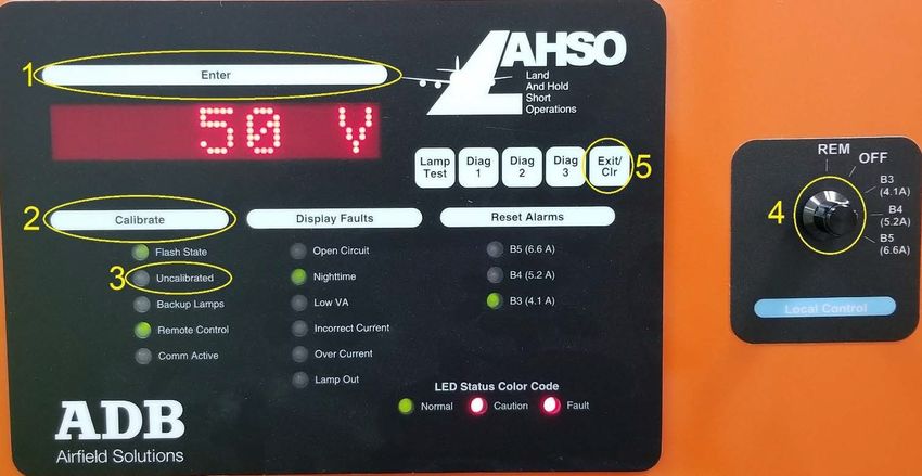
5. Make note of the indicated items below. See Figure 3
a) Item #1 is the Enter button
b) Item #2 is the Calibrate button
c) Item #3 is the Uncalibrated indicator
d) Item #4 is the Remote Local Switch
e) Item #5 is the Exit/Clr button
Figure 11: Front Panel and Remote/Local Switch
6. The first step of the calibration procedure is to turn the Local Control switch to the OFF position. Verify that the LAHSO
unit is off, and no current is flowing in the circuit.
22
Copyright © ADB Safegate, All Rights ReservedCAUTION
Even though the switch is in the OFF position, the LAHSO will turn on during the calibration procedure, so make
sure all personnel are clear of the circuit when the unit cycles through the steps.
Figure 12: Remote/ Local Switch in the OFF position
7. Press the Calibrate button located to the left and below the display screen. The Calibrate button (Item #2) can be seen in
Image #3. The display should show the dialogue as seen in Image #5 below. Note that the LAHSO is not ON at this point.
If there is a need to exit the calibration at any time, use the Exit/Clr button (Item #5) shown in Image #3.
Figure 13: Beginning of the calibration process
Turning ON the LAHSO:
DANGER
The following steps will cause the LAHSO unit to turn ON. Make sure all personnel are aware and clear of the circuit.
96A0235, Rev. R, 2020/09/01 23
Copyright © ADB Safegate, All Rights ReservedL-884 Land and Hold Short Operations
Installation
8. Once it has been confirmed that all fixtures are connected, press the Enter button and the LAHSO will start the calibration
process. The LAHSO display will show “CAL-ALL” and it will start at step B5. At this point, the LAHSO is ON, and current is
flowing in the circuit.
Figure 14: CAL-ALL at Step B5
9. The LAHSO will automatically start cycling through the step to continue the calibration. Verify that the fixtures are flashing
in the field. The below image shows the LAHSO now at step B4.
Figure 15: CAL-ALL at Step B4
24
Copyright © ADB Safegate, All Rights Reserved10. The LAHSO will automatically continue to step B3.
Figure 16: CAL-ALL at Step B3
11. After performing the calibration with all fixtures present, and operational, in the circuit. The LAHSO will turn OFF and the
display will show the dialogue shown in Image #9. The LAHSO is now ready for the two lamps out sequence. At this time,
two fixtures should be removed from the circuit.
Figure 17: 2-OUT/ Start of sequence
96A0235, Rev. R, 2020/09/01 25
Copyright © ADB Safegate, All Rights ReservedL-884 Land and Hold Short Operations
Installation
12. Once the fixtures have been removed and airfield personnel are clear, press the ENTER button and the calibration will
continue. The process is the same as the ALL-CAL sequence. Note that the LAHSO will once again start at Step B5. Verify
that the fixtures are flashing in the field, except for the two that have been removed.
Figure 18: CAL-TWO at Step B5
13. The LAHSO will automatically continue to Step B4.
Figure 19: CAL-TWO at Step B4
26
Copyright © ADB Safegate, All Rights Reserved14. The LAHSO will automatically continue to Step B3.
Figure 20: CAL-TWO at Step B3
Shut OFF the LAHSO
Note
Refer to Table 18 intensity settings.
15. Once the LAHSO has finished with the CAL-TWO sequence, the unit will shut OFF. It is now time to install one of the two
removed fixtures back into the circuit. The following process will be with only one fixture removed from the circuit.
Figure 21: Start of the 1-OUT sequence
96A0235, Rev. R, 2020/09/01 27
Copyright © ADB Safegate, All Rights ReservedL-884 Land and Hold Short Operations
Installation
16. Verify that only one fixture has not been removed from the circuit. If so, then once all personnel are clear of the circuit,
press the ENTER button to continue with the final calibration sequence. As in the previous sequences, the LAHSO will start
the calibration in Step B5. Verify that all but the removed fixture is flashing in the field.
Figure 22: CAL-ONE Step B5
17. 17. The LAHSO will automatically continue to Step B4.
Figure 23: CAL-ONE Step B4
28
Copyright © ADB Safegate, All Rights Reserved18. The LAHSO will automatically continue to Step B3.
Figure 24: CAL-ONE Step B3
19. Once the LAHSO turns OFF, install all removed fixtures. Verify that airfield personnel are clear and then power cycle the
LAHSO unit. Return the Remote/ Local control switch to the “REM” position. The calibration is now complete, and the
“Uncalibrated” indicator should be no longer be lit.
Figure 25: CAL-END/ End of the calibration sequence
20. The link below is to the ADB SAFEGATE LAHSO web page. The latest manual can be obtained by clicking on the “Manual”
tab and downloaded the attached document. The Calibration flowchart is included towards the back of the manual should
there be any questions.
Note
https://adbsafegate.com/product-center/airfield/power-equipment/L-884-LAHSO-PCU-land and-hold-short-
operations-power-and-control-unit
96A0235, Rev. R, 2020/09/01 29
Copyright © ADB Safegate, All Rights ReservedYou can also read