ABB drives for water and wastewater - ACQ580, 0.75 to 500 kW LOW VOLTAGE AC DRIVES
←
→
Page content transcription
If your browser does not render page correctly, please read the page content below
—
LOW VO LTAG E AC D R I V E S

ABB drives for water and wastewater
ACQ580, 0.75 to 500 kW
—
ACQ580 series
Always flowing. Never still.

Water utilities require reliable
solutions securing the flow
of water and wastewater.
The ACQ580 drive for water
is part of ABB’s all-compatible
drives portfolio. This robust
drive is designed to secure
optimal operation of water
and wastewater pumps,
while ensuring low energy
consumption.
—
Table of contents
04–11   The energy efficient drive for water and wastewater pumping
06–07   All-compatible solutions for water and wastewater applications
08–09   Optimizing the flow of water and wastewater in your
        pumping solutions
10      Built-in pump application software
11      General software features of the drive

12–19   How to select a drive
13      Technical specification
14      Securing the flow of water and wastewater with the ACQ580
15      Complete offering from wall-mounted drives to
        cabinet installations
16–17   Overcome challenges of harmonics
18–23   Ratings, types and voltages
24      Dimensions

25–41   Options
25      Comprehensive connectivity
26      Hand-Off-Auto control panel
27      Effortless drive commissioning and use with control panels
28      ABB Ability™ smartphone apps
29      High protection for operation in harsh environments
29      Flange mounting
29      Advanced cooling
30      Quick configuration for unpowered drives
31      Flexible connectivity to automation
32      Thermistor protection modules for increased safety
33      Main disconnect switch for increased safety
34      EMC – electromagnetic compatibility
36      du/dt filters
37–38   du/dt filter selection
39–41   Cooling and fuses

42–45   Motors control and automation products
42      Choose the motor for your water application
43      Ultimate efficiency and reliability to minimize your system cost
        of ownership
44      ABB automation products
45      Securing the flow of water and wastewater in the pump system

46–47   Services to match your needs

48      A lifetime of peak performance

49      ABB Ability™ Condition Monitoring for drives
4                    A B B D R I V E S F O R WAT E R A N D WA S T E WAT E R , A C Q 5 8 0 , 0 .7 5 TO 5 0 0 K W

—
The energy efficient drive
for water and wastewater pumping

Whether your pump system requires redundancy in multi-pump applications
or built-in pump applicaton functionalities designed for the water and
wastewater industry, the ACQ580 is designed to meet your requirements.

                     Simplicity at your fingertips
                     The control panel’s straightforward primary
                     settings menu with assistants helps you
                     set up the drive quickly and effectively.
                     See more on pages 26-27.

Speaks water-specific terminology
The drive has built-in pump application control programs to
secure optimal operation of the water and wastewater pumps.
See more on page 11.

Boosting energy efficiency
The energy optimizer helps you to save energy, and the energy
efficiency information made available to you help monitor and
save the energy used in your processes. The drive meets
IE2 energy efficiency requirements.
See more on page 11.

                     Reliable, integrated safety
                     Safe torque off (STO) built-in as standard
                     and the ATEX certified thermistor protection
                     module, EX II (2) GD, CPTC-02 provides enhanced
                     process safety and easy, simplified installation.
                     See more on page 32-33.

                     Remote monitoring solutions
                     Remote monitoring via standard web browsers
                     will help lower costs by reducing the amount
                     of routine site visits.
                     See more on page 30.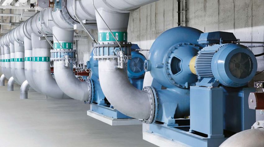
T H E E N E R G Y E F F I C I E N T D R I V E F O R W AT E R A N D W A S T E W AT E R P U M P I N G 5
—
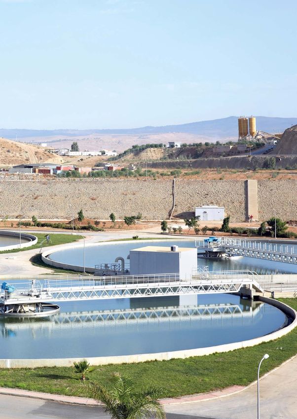
The ACQ580 water and wastewater drives are part of ABB’s all-compatible drives
portfolio. The drives secure the flow of water and wastewater in the pumping system
throughout their whole life cycle. The ACQ580 drive is easy to commission and use.
With built-in pump functionalities, the drive keeps the pumping system operating
optimally, lowering the energy bill. The drive is used in water and wastewater
treament plants, pumping stations, desalination plants, industrial wastewater
facilities and irrigation environments. The drive is used with inflow pumps, transfer
pumps, dosing pumps, sludge pumps, booster pumps, submersible pumps and
compressors, blowers, decanter centrifuges, mixers and fans.
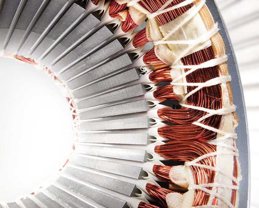
Controls virtually any kind of motor
The drive has the ability to control almost any motors from induction
and permanent magnet motors to synchronous reluctance motors.
See more on pages 42-45.
Startup and maintenance tool
Drive composer PC tool for startup,
configuration, monitoring and process tuning.
The PC tool is connected to the driveʼs control
panel with a standard USB cable.
See more on page 30.
Robust with built-in features
A robust performer with enclosure class up to IP55, that is simple
to select, and easy to install and use. Built-in features such as an
EMC filter, choke, a Modbus RTU fieldbus interface and safe torque
off (STO) functionality simplify drive selection, installation and use.
See more on pages 29, 37.
Reliable communication
With its wide range of optional fieldbus
adapters and embedded RTU Modbus, the drive
enables connectivity with all major automation
networks and control systems.
See more on page 31.
Input/output extensions
In addition to the standard interfaces,
the drive has a built-in slot for additional
input/output extension modules.
See more on page 31.
Ultra-low harmonic (ULH) solution for a clean network
The ACQ580 ultra-low harmonic drive is designed to minimize the
effect of harmonics distortion on your electrical system. The drive
keeps the network in the waterutility clean and stable. As a result
electrical equipments in the plant wastes less energy in heat and
less unwelcome disturbance occur.
See more on pages 16-17.
6                    A B B D R I V E S F O R WAT E R A N D WA S T E WAT E R , A C Q 5 8 0 , 0 .7 5 TO 5 0 0 K W

—
All-compatible solutions for water
and wastewater applications
Environment all-compatible                                                   Process all-compatible
Achieve your environmental goals with our energy-efficient                   Water and wastewater processes consist of many phases
drive for water and wastewater. The all-compatible drives                    which require optimal performance of your pump solution
offer built-in energy efficiency calculators. They help you                  from start to finish. Our robust drives are available with
to analyze and optimize your pump processes to reduce                        enclosures up to IP55. The drive controls virtually any kind
stress on the environment. Other environmentally friendly                    of motors from induction and permanent magnet motors
features include the built-in soft pipe fill function to                     to synchronous reluctance motors up to 500 kW. The drive
ensure less water hammering on the water pipes, thus                         is compatible with a wide range of fieldbus protocols,
preventing the risk of unwanted leaks, unplanned outage                      ensuring reliable communication between the drive and
and repair costs.                                                            automation system in use.

ART
                     A L L-I CL
                             C OEMOR
                                  PATCH
                                     I B LAP
                                           E TSER
                                               O LU
                                                  T ITTL
                                                       I OEN S F O R W AT E R A N D W A S T E W AT E R A P P L I C AT I O N S              7

Business all-compatible                                                          Human all-compatible
As a reliable global partner, we provide water process                           You can feel confident using our all-compatible drives
solutions that help to keep the life cycle costs of your pump                    for water and wastewater. The drive speaks the language
solution stable. Additionally, we help keep your water                           of your pump application, making it easy to set up,
process productive and consistent in an energy efficient                         configure and use. The intuitive Hand-Off-Auto control
way. Our wide range of water industry products and                               panel ensures that you have access to the essential
solutions offer optimal flow of water all hours of the day.                      information quickly. For accessing your drive from
This means lower energy consumption, improved                                    a distance and receiving valuable analytics, we offer
productivity, flexibility and ease of use. With offices in                       remote monitoring solutions.
over 90 countries and a global technical partner network,
we offer technical advice and local support worldwide.
8                     A B B D R I V E S F O R WAT E R A N D WA S T E WAT E R , A C Q 5 8 0 , 0 .7 5 TO 5 0 0 K W

—
Optimizing the flow of water and
wastewater in your pumping solutions
The ACQ580 water and wastewater drive is built to help users, designers, OEMs,
system integrators and EPC professionals secure pumping of water and wastewater
in municipal utilities, pumping stations, industrial wastewater facilities, desalination
plants and irrigation environments. It offers long-term, technically-compatible drive
solutions supported by full service and support.

Soft pipe filling
Increase the lifetime of the piping
and pump system by avoiding
pressure peaks.

Quick ramps
Extend the lifecycle of a submersible
pumps by reducing wear of the
mechanical parts using ramp sets to
accelerate and decelerate the pumps.

Pump priority
Achieve energy savings with optimal
pump alternation by running the higher
capacity pumps when the consumption
rate is higher.

                                                                              Multi-pump control
                                                                              Ensure stable and uninterrupted production with
                                                                              multi-pump controls by optimizing the speed and
                                                                              number of running pumps.
O P T I M I Z I N G T H E F LO W O F W AT E R A N D W A S T E W AT E R I N YO U R P U M P I N G S O LU T I O N S                 9

Sleep boost                                                                                Auto-change
Save energy while extending the life                                                       Increase the mean time between repairs
time of the pumps and motors by                                                            and save in service costs by balancing
decreasing start/stop cycles during                                                        the long-term operation time of all
all hours of the day.                                                                      pumps in a parallel pumping system.

                                                                                                                 Level control
                                                                                                                 Ensures optimal efficiency
                                                                                                                 when filling or emptying a tank.

                                                                                                                 Sensorless flow calculation
                                                                                                                 Reduce costs by eliminating the
                                                                                                                 need for external components
                                                                                                                 or backup the flow meters to
                                                                                                                 avoid interruptions in the
                                                                                                                 process.

                                                                                                                 Flow and pressure protection
                                                                                                                 The drive protects the pumping
                                                                                                                 system from a low and / or high
                                                                                                                 pressure and flow, as well as
                                                                                                                 prevents the pump from
                                                                                                                 running dry.

                                                                                           Pump cleaning
                                                                                           Achieve savings by preventing unplanned
                                                                                           downtime. This is made possible as a result of
                                                                                           accumulating obstructions being removed
                                                                                           from the impeller of the pump.
10                    A B B D R I V E S F O R WAT E R A N D WA S T E WAT E R , A C Q 5 8 0 , 0 .7 5 TO 5 0 0 K W

—
Built-in pump application software
The built-in pump application software in the ACQ580 drives is designed to enhance
the reliability and durability of the water and wastewater application in which it is
used. The functions protect the pump and secure its optimal functionality, increasing
cost efficiency. The built-in functionalities also support the user in securing the flow
of the water and wastewater in the pump solution.

                    Multi-pump functionality                                                  Pump cleaning
                    The function maintains stable                                             Keeps the impeller of the pump clean by running
                    process conditions for several parallell                                  a sequence of aggressive ramps between
                    pumps (up to 8 pumps at the same                                          minimum and maximum pump speed.
time) operating together. It is possible to optimize the
speed and number of pumps needed when the required
flow or pressure rate is variable. This built-in functionality                           Turbidity reduction
ensures continuous operation for multipump systems                                       When a pump starts as slow as possible, it
even if one or more pumps fails or requires maintenance.                                 creates the lowest turbidity values for the water
                                                                                         being moved or extracted. When you combine
                                                                              quick ramps and long normal ramps, the drive will protect
            Sensorless flow calculation                                       and run submersible pump most optimal way.
            Measures the amount of water flowing without
            the need for external sensors. This will enable
            you to reduce costs as there is no need for                                   Pump protection
setting up and using additional sensors or back up the flow                               The built-in protection functionalities ensures
meters to avoid interruptions in the process.                                             that pumps can operate at the best possible
                                                                                          conditions. The maximum pressure protections
                                                                              help to protect the pump and the system in case of a
             Level control                                                    blockage in the pipeline. In case of a pipe rupture, the
             Control the filling or emptying of wastewater                    minimum pressure protection can generate an alarm or fault
             storage and water tower tanks. Level control can                 or can be programmed to run at certain speed to avoid dirty
             be used within a station controlling up to eight                 water entering the pipeline. The inlet pressure protection
pumps. The level control function has varying pre-set water                   can help to avoid cavitation. When the inlet pressure of a
levels and the pumps will start and stop based on measured                    water pump falls below pump design specifications, tiny
level. This method allows the pumps to run at an efficicent                   vapor bubbles form. These bubbles collapse when they meet
speed and ensures the pump sump does not become over                          the impeller, causing shock waves and points of high
contaminated by sediment.                                                     temperature that can corrode the surface of the impeller.

           Soft pipe fill                                                                  Dry run protection
           The soft pipe fill function manages the pressure                                This function prevents the pump from running
           of water by filling the pipeline with a gentle                                  dry. The water pump shaft and impeller are
           approach. This helps to avoid sudden pressure                                   rotating at fast rates. If there is no dry pump
peaks and reduces the risk of water hammer which can                          protection, the released heat can damage the pump over
cause damage to the water pipes.                                              time, limiting its lifetime.

             Quick-ramp
             Protect bearings when a submersible pump is
             started without water. Quick ramp allows your
             pump to reach optimal speed to extend pump
life, ensure operation and prevent unplanned outages.
A B B D R I V E S F O R WAT E R A N D WA S T E WAT E R , A C Q 5 8 0 , 0 .7 5 TO 5 0 0 K W 11
—
General software features of the drive
With a pump control software one drive controls several pumps
or blowers in parallel and eliminates the need for an external
programmable logic controller. This results in reduced stress
on the mains and the system as well as in lower
maintenance and operation costs.
Startup assistant allows first-time users to quickly
customize the drive, out of the box, according to
their needs. This is complemented by a built-in help
function to make parameter-by-parameter setting easy.
Enjoy sophisticated process control in scalar and
vector control modes. They support a wide range of
motors including induction, permanent magnet
and synchronous reluctance motors.
The energy optimizer feature operates both in
scalar and vector control modes, ensuring
maximum torque per ampere and reducing energy
drawn from the supply. You can follow the saved
energy, CO₂ emissions or money, and see how fast
the drive brings you a return on investment.
The drive reduces motor noise by spreading the
switching frequencies over a user-specified range.
The higher used switching frequency reduces motor
noise at low load without limiting
full current at maximum load.
Diagnostic assistant helps in locating the cause of
any disturbance to the drive, and even suggests
possible remedies. This reduces process downtime
by making repairs or adjustments effortless.
A built-in and stand-alone process PID/loop controller makes
the drive a self-governing unit that requires no external logic input from
the control room but requires only an external process measurement.
Load profile feature collects drive values, such as current and stores them in a log.
This enables you to analyze and optimize the application with the help of historical data load.
Adaptive programming provides extra flexibility by offering
easy alternative for simple programming needs.12 A B B D R I V E S F O R WAT E R A N D WA S T E WAT E R , A C Q 5 8 0 , 0 .7 5 TO 5 0 0 K W
—
How to select a drive?
It is very easy to select the right drive. This is how you build up
your own ordering code using the type designation key.
3 4
Start with identifying your supply voltage. 1
This tells you what rating table to use.
The ACQ580 supports 200 to 480 V. Type designation: ACQ580 – 01 – XXXX – X + XXXX
04
Product series
07
Choose your motor’s nominal power rating 2 31
from the ratings table on pages 18-23. 34
Types and construction
Rating
Voltage
Options
Select your drive’s type code 3
Example configuration:
from the rating table based on your
ACQ580-01-145A-4+B056+J400+L501
motor's nominal power rating.
Wall-mounted 145 A, 400 V drive in IP55 enclosure with Hand-Off-Auto
control panel and internal CMOD-01 input/output option
Choose your options. 4 18 A B B D R I V E S F O R WAT E R A N D WA S T E WAT E R , A C Q 5 8 0 , 0 .7 5 TO 5 0 0 K W 18 A B B D R I V E S F O R WAT E R A N D WA S T E WAT E R , A C Q 5 8 0 , 0 .7 5 TO 5 0 0 K W
Details about each option begin on page 26. —
Ratings, types and voltages
—
Ratings, types and voltages
Add the option codes to the end of the drive’s ACQ580-01, wall-mounted drives ACQ580-01, wall-mounted drives
ordering code. Remember to use a "+" before
2 3
each option code.
3-phase, U N = 230 V (range 200 to 240 V). The power ratings are valid at nominal voltage 230 V (0.75 to 75 kW) 3-phase, U N = 230 V (range 200 to 240 V). The power ratings are valid at nominal voltage 230 V (0.75 to 75 kW)
Drive type Frame Nominal ratings Light-overload use Maximum Drive type Frame Nominal ratings Light-overload use Maximum
size output current size output current
IN PN I Ld PLd I Max IN PN I Ld PLd I Max
(A) (kW) (A) (kW) (A) (A) (kW) (A) (kW) (A)
ACQ580-01-04A7-2 R1 4.7 0.75 4.6 0.75 6.3 ACQ580-01-04A7-2 R1 4.7 0.75 4.6 0.75 6.3
Control panels....................................................... 26-27
ACQ580-01-06A7-2 R1 6.7 1.1 6.6 1.1 8.9 ACQ580-01-06A7-2 R1 6.7 1.1 6.6 1.1 8.9
ACQ580-01-07A6-2 R1 7.6 1.5 7.5 1.5 11.9 ACQ580-01-07A6-2 R1 7.6 1.5 7.5 1.5 11.9
ACQ580-01-012A-2 R1 12 3 11.8 3 19.1 ACQ580-01-012A-2 R1 12 3 11.8 3 19.1
ACQ580-01-018A-2 R1 16.9 4 16.7 4 22 ACQ580-01-018A-2 R1 16.9 4 16.7 4 22
ACQ580-01-025A-2 R2 24.5 5.5 24.2 5.5 32.7 ACQ580-01-025A-2 R2 24.5 5.5 24.2 5.5 32.7
Protection classes...................................................... 29
ACQ580-01-032A-2 R2 31.2 7.5 30.8 7.5 43.6 ACQ580-01-032A-2 R2 31.2 7.5 30.8 7.5 43.6
ACQ580-01-047A-2 R3 46.7 11 46.2 11 62.4 ACQ580-01-047A-2 R3 46.7 11 46.2 11 62.4
ACQ580-01-060A-2 R3 60 15 59.4 15 83.2 ACQ580-01-060A-2 R3 60 15 59.4 15 83.2
ACQ580-01-089A-2 R5 89 22 88 22 135 ACQ580-01-089A-2 R5 89 22 88 22 135
ACQ580-01-115A-2 R5 115 30 114 30 158 ACQ580-01-115A-2 R5 115 30 114 30 158
Flange mounting......................................................... 29
ACQ580-01-144A-2 R6 144 37 143 37 205 ACQ580-01-144A-2 R6 144 37 143 37 205
ACQ580-01-171A-2 R7 171 45 169 45 257 ACQ580-01-171A-2 R7 171 45 169 45 257
ACQ580-01-213A-2 R7 213 55 211 55 304 ACQ580-01-213A-2 R7 213 55 211 55 304
ACQ580-01-276A-2 R8 276 75 273 75 380 ACQ580-01-276A-2 R8 276 75 273 75 380
Quick configuration.................................................. 30
Remote monitoring .................................................. 30
Fieldbus adapters....................................................... 31
I/O extension and
thermistor protection modules........................ 32-33
EMC............................................................................... 34 Pages 18-23 Pages 18-23
du/dt....................................................................... 36-38
A B B D R I V E S F O R WAT E R A N D WA S T E WAT E R , A C Q 5 8 0 , 0 .7 5 TO 5 0 0 K W 27
—
Effortless drive commissioning
and use with control panels
A variety of different control panel variants and panel accessories are available for
the ACQ580 drives. Drive setup, maintenance, diagnostics and process monitoring
is done via the control panel in an effortless manner.
— — — —
01 02 03 04
— —
01 Hand-Off-Auto control panel and 04 The DPMP-01 control panel
Help function are included as standard. mounting platform is for flush
USB connection as standard. mountings. It does not include the
control panel. When using this with
— ACQ580, also CDPI-01 is required.
02 The optional Hand-Off-Auto control
panel with Bluetooth functionality. —
USB connection as standard. 05 The DPMP-02 mounting platform
is for surface mounting. It does
— not include the control panel.
03 By using the panel bus adapter, When using this with ACQ580,
CDPI-01 the assistant control panel also CDPI-01 is required.
is able to manage up to 32 drives.
—
— — 06 The door mounting kit DPMP-
05 06 EXT is a ready-made kit consisting
4
of the DPMP-02 and CDPI-01.
—
Control panel options
Option code Description Type designation
+J400 The Hand-Off-Auto control panel as standard in the delivery ACH-AP-H
+J429 Control panel with Bluetooth interface ACH-AP-W
+J425 Assistant Control panel with local/remote -logic ACS-AP-I
+J424 Blank control panel cover (no control panel delivered) CDUM-01
3AXD50000004419 Panel bus adapter CDPI-01
3AUA0000108878 Control panel mounting platform DPMP-01
(flush mounted, requires also panel bus adapter on the drive)
3AXD50000009374 Control panel mounting platform DPMP-02
(surface mounted, requires also panel bus adapter on the drive)
3AXD50000016230 * )
Control panel mounting platform DPMP-03
(surface mounted, requires also panel bus adapter on the drive, only for ACQ580-04/34)
3AXD50000217717 *) Control panel mounting kit for outdoor installation DPMP-04
3AXD50000240319 *) Control panel mounting kit for outdoor installation, only for ACQ580-04/34 DPMP-05
3AXD50000010763 Door mounting kit for the panel (for one drive, contains both DPMP-02 and CDPI-01) DPMP-EXT
*) For availability please contact your local ABB
Pages 27-41A B B D R I V E S F O R WAT E R A N D WA S T E WAT E R , A C Q 5 8 0 , 0 .7 5 TO 5 0 0 K W 13
—
Technical specification
Mains connection Environmental limits
Voltage range 3-phase, U N Ambient
temperature
Power range ACQ580-01 0.75 to 250 kW
wall-mounted (frame sizes R1 to R9) Transport -40 to +70 °C
Storage -40 to +70 °C
ACQ580-04 250 to 500 kW
module (frame sizes R10 to R11) Operation area ACQ580-01/-31 -15 °C to 50 °C. No frost
allowed.
ACQ580-07 75 to 500 kW From +40 °C to +50 °C with
cabinet (frame sizes R6 to R11) derating1% per 1 °C.
ACQ580-31 4 to 110 kW ACQ580-04/-34 -15 °C to 55 °C. No frost
ULH wall-mounted (frame sizes R3, R6 and R8) allowed.
ACQ580-34 132 to 355 kW From +40 °C to +55 °C with
ULH module (frame size R11) derating 1% per 1 °C.
Frequency 50/60 Hz ±5% ACQ580-07 0 °C to +50 °C. No frost
allowed.
Power factor
From +40 °C to +50 °C with
(-01, -04, -07) cosϕ = 0.98
derating 1% per 1 °C.
(-31, -34) cosϕ = 1
Cooling method
Efficiency Air-cooled Dry clean air
(at nominal power) 98%
Altitude
Motor connection 0 to 1.000 m Without derating
Voltage 0 to U N , 3-phase 1.000 to 4.000 m With derating of 1%/100 m
Frequency 0 to 500 Hz Relative humidity 5 to 95%. no condensation allowed
Degree of ACQ580-01/-31 IP21 (UL Type 1) and
Motor control Scalar and vector control
protection IP55 (UL Type 12)
Speed control Static accuracy: 20% of motor nominal slip
ACQ580-04/-34 IP00 as standard and
Dynamic accuracy: 1% seconds with
IP20 as option
100% torque step
ACQ580-07 IP21 as standard,
Product compliance IP42 and IP54 as option
CE Functional safety Safe torque off
Low Voltage Directive 2014/35/EU, EN 61800-5-1:2007 (STO according EN 61800-5-2)
Machinery Directive 2006/42/EC, EN 61800-5-2:2007 IEC 61508 ed2: SIL 3, IEC 61511: SIL 3,
EMC Directive 2014/30/EU, EN 61800-3:2004 + A1:2012 IEC 62061: SIL CL 3, EN ISO 13849-1: PL e
RoHS directive 2011/65/EU Contamination
Waste electrical and electronic equipment directive (WEEE) 2000/96/EC levels No conductive dust allowed
Quality assurance system ISO 9001 and Environmental system
Storage IEC 60721-3-1. Class 1C2 (chemical gases).
RCM, EAC, Ul, cUL
Class 1S2 (solid particles)*)
TÜV Nord (safety functions)
Operation IEC 60721-3-3. Class 3C2 as standard and 3C3 as
EMC according to EN 61800-3:2004 + A1:2017 option (chemical gases). Class 3S2 (solid particles)*)
ACQ580-01/-31 Class C2 as standard Transportation IEC 60721-3-2. Class 2C2 (chemical gases).
ACQ580-04/-34 Class C3 as standard Class 2S2 (solid particles)*)
ACQ580-07 Class C2 as standard for powers 75 kW to 250 kW and *) C = chemically active substances
S = mechanically active substances
Class C3 as standard for powers 250 kW to 500 kW
Harmonic mitigation
Built-in swinging choke as standard in ACQ580-01 meets the
requirements of IEC 61000-3-12: 2011.
ACQ580-31 and ACQ580-34 in addition meets the requirements
of IEEE519 and G5/4.14 A B B D R I V E S F O R WAT E R A N D WA S T E WAT E R , A C Q 5 8 0 , 0 .7 5 TO 5 0 0 K W
—
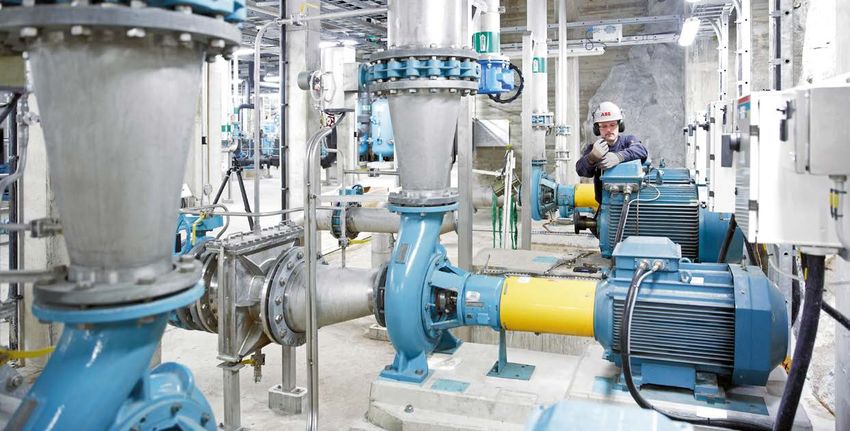
Securing the flow of water and
wastewater with the ACQ580
The ACQ580 is a robust and compact drive ensuring low energy consumption
and continuous, reliable motor control with a power and voltage range from
0.75 to 500 kW and 200 to 480 V. It has coated boards and offers enclosure
classes up to IP55 for different environments. The drive is designed for water
and wastewater pumps, blowers, mixers, centrifuges and fans.
—
01 The ACQ580 Built-in pump functionality for optimal flow of water
drive series
Built-on ABB’s common drives architecture, the drive
— offers pump operation, energy savings and usability
02 Flange mounting
for panel installation
benefits supported by a local network of service and
ensures less thermal support. The water and wastewater drive has several
load inside the panel
by keeping most of
different built-in pump application features for
the losses outside optimal pump operation (see page 10).
the panel.
Intuitive usability supported by simple connectivity
To ensure fast set-up and operation of the drive,
adjusting drive settings has been made easy with
the robust and intuitive Hand-Off-Auto control panel.
The control panel has a powerful diagnostics menu
that makes it possible to quickly access information,
even in facilities with poor visibility. Drive usability is
further enhanced via wireless Bluetooth connectivity
between the drive and mobile devices, making it easy
to access the drive in difficult-to-reach locations.
—
Connectivity to automaton systems is ensured with 01
the drive connecting to various fieldbus protocols.
To ensure compliance with electric grids, the ACQ580
has a built-in 1st environment EMC filter and choke.
The drive also supports functional safety design,
as it offers integrated safety features with safe
torque off (STO) built-in as standard.
The wall-mounted drive (ACQ580-01, -31) offers
flange mounting as an option, separating the control
electronics from the main circuit cooling airflow, saving
space and ensuring optimal cooling and extends the
lifetime of the drive. The cabinet-built drive (ACQ580-07)
offers flange mounting as a standard solution. This results
in better thermal management in panel installation.
The advanced pedestal system and ramp of the drive
module (ACQ580-04, -34) ensure easy installation and —
reduce time needed for setup and commissioning. 02A B B D R I V E S F O R WAT E R A N D WA S T E WAT E R , A C Q 5 8 0 , 0 .7 5 TO 5 0 0 K W 15
—
Complete offering from wall-mounted
drives to cabinet installations
No matter the frame size or power range, all ACQ580 drives
bring you ease of use, scalability and quality.
—
01 Wall-mounted IP21 The wall-mounted IP21 drives
drive (ACQ580-01)
The wall-mounted IP21 drives are available with the
— power and voltage range from 0.75 to 250 kW and 3-ph —
02 Wall-mounted IP55 01
drive (ACQ580-01+B056)
200 to 480 V. Side-by-side mounting, flange mounting
and horizontal mounting are all available for the
—
03 Drive module
wall-mounted ACQ580 drives.
IP00 (ACQ580-04)
—
The wall-mounted IP55 drives
04 Cabinet-built IP42 The IP55 drive is designed for applications exposed to
drive (ACQ580-07+B054)
dust, moisture, vibrations and other harsh environments.
It is similar in size to the compact IP21 drives, which —
02
provides significant savings in space, maintenance,
engineering, material costs, as well as in setup and
commissioning time.
Drive modules for cabinet installations
The ACQ580 drive modules are optimal for system
integrators, cabinet builders or OEMs who want to
optimize the cabined design in the 250 to 500 kW range,
but do not want to compromise the easy installation,
commissioning and maintenance.
Cabinet-built drives —
The cabinet-built drives are type tested ABB solutions 03
offering robust but easy to use cabinets with a new and
innovative cooling arrangement. The ABB made cabinets
have many in-built features as standard, delivered with
short lead times and always made according to ABB’s
high quality standards. The design is available as standard
for all available protection classes IP21 / 42 / 54 in frames
R6 to R11. The power and voltage range is from 75 kW to
500 kW, 3-ph 380 to 480 V.
To select IP classes for the drive see page 24.
—
0416 A B B D R I V E S F O R WAT E R A N D WA S T E WAT E R , A C Q 5 8 0 , 0 .7 5 TO 5 0 0 K W
—
Overcome challenges of harmonics
ACQ580 ultra-low harmonic drives have excellent harmonics performance
and are perfectly suited for places that cannot handle high harmonic content
in the network.
The problem with harmonics Harmonics may cause premature failure or
Generators in power plants rotate at constant reduced lifespan of other electrical equipment
and regulated speed, resulting in a sine-wave caused by the overheating of network
shaped current in an AC grid in the ideal case. components like transformers and cables.
Harmonics in the network are also responsible
for disturbing other electrical equipment in
the network that require a pure sinusoidal
AC-waveform. Harmonics may also cause
unstable operation in back-up generators.
All-in-one concept for a clean network
ABBʼs ultra-low harmonic (ULH) drives for water
are designed with built-in harmonic avoidance
systems and complies with IEC61000-3-12.
However, in the modern world, the network is not
Also extremely low harmonic content helps your
pure sine wave. Electricity networks are affected
system to meet IEEE519 and G5/4 harmonic
by harmonics: higher-order oscillations introduced
recommendations. Compared to other
by various types of electrical equipment.
harmonic mitigation solutions, the problems
caused by harmonics are avoided in the first
place. ULH drives have excellent harmonic
performance technology built-in, including active
supply unit and integrated low harmonic line
filter. There is no need for external harmonic
filters or multi-pulse transformers, leading to
significant savings in the footprint.
Full water functionality and
clean supply (THDi less than 3%)
The benefits of a drive
without the inconvenience
of harmonics
Savings on investments
and during the lifetime
Major
benefits
Effortlessly meets
harmonic standards
and specification
Reliability for
your facility
Quick and easy Simple to install – three wires in, three wires out.
maintenance No external hardware required.OVERCOME CHALLENGES OF HARMONIC S 17
Reliable operation under special conditions factor. With an integrated design that leverages
ULH drives ensure that the motor receives the drive technology as part of the harmonic
full voltage, even in low-voltage utility condition solution, there is no risk of nuisance trips due
or in a fluctuating network. Thanks to the drives’ to incompatible components, no need for
capability to provide an output voltage up to additional hardware and no additional
15 percent greater than the supply voltage, cooling requirements.
applications can overcome voltage drops caused
by long supply or motor cables. All this is done Compared to other harmonic mitigation
without costly additional equipment or oversizing solutions, like passive and active filters, system
of drive system components. level efficiency is better when there are less
components in the network. Also there is savings
Savings in total cost of ownership in the installation and maintenance costs.
Electrical utilities may charge additional penalties
for consuming reactive power. The ULH drives In retrofit projects, the transformer might not be
has unity true power factor as a result of its low dimensioned to meet the harmonic levels caused
harmonics and no consumption of reactive power. by non-linear loads such as standard 6-pulse
Additionally, the drive is able to compensate the drives, so there is a risk of overloading the
displacement power factor of the network, to transformer. Thanks to the extremely low
which it is connected. This reduces the risk harmonic content of ULH drives there is no need
of having additional running costs or buying to overdimension the transformer, switchgear,
additional capacitor banks to correct the power or cables.18 A B B D R I V E S F O R WAT E R A N D WA S T E WAT E R , A C Q 5 8 0 , 0 .7 5 TO 5 0 0 K W
—
Ratings, types and voltages
ACQ580-01, wall-mounted drives
3-phase, U N = 230 V (range 200 to 240 V). The power ratings are valid at nominal voltage 230 V (0.75 to 75 kW)
Drive type Frame Nominal ratings Light-overload use Maximum
size output current
IN PN I Ld PLd I Max
(A) (kW) (A) (kW) (A)
ACQ580-01-04A7-2 R1 4.7 0.75 4.6 0.75 6.3
ACQ580-01-06A7-2 R1 6.7 1.1 6.6 1.1 8.9
ACQ580-01-07A6-2 R1 7.6 1.5 7.5 1.5 11.9
ACQ580-01-012A-2 R1 12 3 11.8 3 19.1
ACQ580-01-018A-2 R1 16.9 4 16.7 4 22
ACQ580-01-025A-2 R2 24.5 5.5 24.2 5.5 32.7
ACQ580-01-032A-2 R2 31.2 7.5 30.8 7.5 43.6
ACQ580-01-047A-2 R3 46.7 11 46.2 11 62.4
ACQ580-01-060A-2 R3 60 15 59.4 15 83.2
ACQ580-01-089A-2 R5 89 22 88 22 135
ACQ580-01-115A-2 R5 115 30 114 30 158
ACQ580-01-144A-2 R6 144 37 143 37 205
ACQ580-01-171A-2 R7 171 45 169 45 257
ACQ580-01-213A-2 R7 213 55 211 55 304
ACQ580-01-276A-2 R8 276 75 273 75 380R AT I N G S , T Y P E S A N D V O LTA G E S 19
3-phase, U N = 400 V (range 380 to 480 V). The power ratings are valid at nominal voltage 400 V (0.75 to 250 kW)
Drive type Frame Nominal ratings Light-overload use Maximum
size output current
IN PN I Ld PLd I Max
(A) (kW) (A) (kW) (A)
ACQ580-01-02A7-4 R1 2.6 0.75 2.5 0.75 3.2
ACQ580-01-03A4-4 R1 3.3 1.1 3.1 1.1 4.7
ACQ580-01-04A1-4 R1 4 1.5 3.8 1.5 5.9
ACQ580-01-05A7-4 R1 5.6 2.2 5.3 2.2 7.2
ACQ580-01-07A3-4 R1 7.2 3 6.8 3 10.1
ACQ580-01-09A5-4 R1 9.4 4 8.9 4 13
ACQ580-01-12A7-4 R1 12.6 5.5 12 5.5 14.1
ACQ580-01-018A-4 R2 17 7.5 16.2 7.5 22.7
ACQ580-01-026A-4 R2 25 11 23.8 11 30.6
ACQ580-01-033A-4 R3 32 15 30.4 15 44.3
ACQ580-01-039A-4 R3 38 18.5 36.1 18.5 56.9
ACQ580-01-046A-4 R3 45 22 42.8 22 67.9
ACQ580-01-062A-4 R4 62 30 58 30 76
ACQ580-01-073A-4 R4 73 37 68.4 37 104
ACQ580-01-088A-4 R5 88 45 83 45 122
ACQ580-01-106A-4 R5 106 55 100 55 148
ACQ580-01-145A-4 R6 145 75 138 75 178
ACQ580-01-169A-4 R7 169 90 161 90 247
ACQ580-01-206A-4 R7 206 110 196 110 287
ACQ580-01-246A-4 R8 246 132 234 132 350
ACQ580-01-293A-4 R8 293 160 278 160 418
ACQ580-01-363A-4 R9 363 200 345 200 498
ACQ580-01-430A-4 R9 430 250 400 200 545
Nominal ratings
IN Rated current available continuously without overloadability at 40 °C.
PN Typical motor power in no-overload use.
Maximum output current
I max Maximum output current. Available for 2 seconds at start, then as long as allowed by drive temperature.
Light-overload use
I Ld Continuous current allowing 110% I Ld for 1 minute every 10 minutes at 40 °C.
P Ld Typical motor power in light-overload use.
The ratings apply for the frames R1 to R9 up to +40 °C in enclosed IP class 21/55.
For derating at high altitudes, temperatures or switching frequencies, see the user’s HW manual, document code: 3AXD50000035866.20 A B B D R I V E S F O R WAT E R A N D WA S T E WAT E R , A C Q 5 8 0 , 0 .7 5 TO 5 0 0 K W
—
Ratings, types and voltages
ACQ580-04, drive modules
3-phase, U N = 400 V (range 380 to 480 V). The power ratings are valid at nominal voltage 400 V (250 to 500 kW)
Drive type Frame Nominal ratings Light-overload use Maximum
size output current
IN PN I Ld PLd I Max
(A) (kW) (A) (kW) (A)
ACQ580-04-505A-4 R10 505 250 485 250 560
ACQ580-04-585A-4 R10 585 315 575 315 730
ACQ580-04-650A-4 R10 650 355 634 355 730
ACQ580-04-725A-4 R11 725 400 715 400 1020
ACQ580-04-820A-4 R11 820 450 810 450 1020
ACQ580-04-880A-4 R11 880 500 865 500 1100
Nominal ratings
IN Rated current available continuously without overloadability at 40 °C.
PN Typical motor power in no-overload use.
Maximum output current
I max Maximum output current. Available for 2 seconds at start, then as long as allowed by drive temperature.
Light-overload use
I Ld Continuous current allowing 110% I Ld for 1 minute every 10 minutes at 40 °C.
P Ld Typical motor power in light-overload use.
The ratings apply for the frames R10 to R11 up to +40 °C in enclosed IP class 00/20.
For derating at high altitudes, temperatures or switching frequencies, see the user’s HW manual, document code: 3AXD50000048677.R AT I N G S , T Y P E S A N D V O LTA G E S 21
—
Ratings, types and voltages
ACQ580-07, cabinet-built drives
3-phase, U N = 400 V (range 380 to 480 V). The power ratings are valid at nominal voltage 400 V (75 to 250 kW)
Drive type Frame Nominal ratings Light-overload use Maximum
size output current
IN PN I Ld PLd I Max
(A) (kW) (A) (kW) (A)
ACQ580-07-0145A-4 R6 145 75 138 75 178
ACQ580-07-0169A-4 R7 169 90 161 90 247
ACQ580-07-0206A-4 R7 206 110 196 110 287
ACQ580-07-0246A-4 R8 246 132 234 132 350
ACQ580-07-0293A-4 R8 293 160 278 160 418
ACQ580-07-0363A-4 R9 363 200 345 200 498
ACQ580-07-0430A-4 R9 430 250 400 200 545
ACQ580-07-0505A-4 R10 505 250 485 250 560
ACQ580-07-0585A-4 R10 585 315 575 315 730
ACQ580-07-0650A-4 R10 650 355 634 355 730
ACQ580-07-0725A-4 R11 725 400 715 400 1020
ACQ580-07-0820A-4 R11 820 450 810 450 1020
ACQ580-07-0880A-4 R11 880 500 865 500 1100
Nominal ratings
IN Rated current available continuously without overloadability at 40 °C.
PN Typical motor power in no-overload use.
Maximum output current
I max Maximum output current. Available for 2 seconds at start, then as long as allowed by drive temperature.
Light-overload use
I Ld Continuous current allowing 110% I Ld for 1 minute every 10 minutes at 40 °C.
P Ld Typical motor power in light-overload use.
The ratings apply for the frames R6 to R11 up to +40 °C in enclosed IP class 21/42/54.
For derating at high altitudes, temperatures or switching frequencies, see the user’s HW manual, document code: 3AXD50000045817.22 A B B D R I V E S F O R WAT E R A N D WA S T E WAT E R , A C Q 5 8 0 , 0 .7 5 TO 5 0 0 K W
—
Ratings, types and voltages
ACQ580-31, ultra-low harmonic drives
3-phase, UN = 400 V (range 380 to 480 V). The power ratings are valid at nominal voltage 400 V (4 to 110 kW)
Drive type Frame Nominal ratings Light-overload use Maximum
size output current
IN PN I Ld PLd I Max
(A) (kW) (A) (kW) (A)
ACQ580-31-09A5-4 R3 9.4 4 8.9 4 12.2
ACQ580-31-12A7-4 R3 12.6 5.5 12 5.5 16.1
ACQ580-31-018A-4 R3 17 7.5 16 7.5 21.4
ACQ580-31-026A-4 R3 25 11 24 11 28.8
ACQ580-31-033A-4 R6 32 15 30 15 42.5
ACQ580-31-039A-4 R6 38 18.5 36 18.5 54.4
ACQ580-31-046A-4 R6 45 22 43 22 64.6
ACQ580-31-062A-4 R6 62 30 59 30 77.5
ACQ580-31-073A-4 R6 73 37 69 37 105.4
ACQ580-31-088A-4 R6 88 45 84 45 124.1
ACQ580-31-106A-4 R8 106 55 101 55 149.6
ACQ580-31-145A-4 R8 145 75 138 75 181.3
ACQ580-31-169A-4 R8 169 90 161 90 246.5
ACQ580-31-206A-4 R8 206 110 196 110 287.3
Nominal ratings
IN Rated current available continuously without overloadability at 40 °C.
PN Typical motor power in no-overload use.
Maximum output current
I max Maximum output current. Available for 2 seconds at start.
Light-overload use
I Ld Continuous current allowing 110% I Ld for 1 minute every 10 minutes at 40 °C.
P Ld Typical motor power in light-duty use.
The ratings apply for frames R3, R6 and R8 up to +40 °C in enclosed IP class 21/55.
For derating at higher altitudes, temperatures or switching frequencies, see the HW manual, document code 3AXD50000045935.R AT I N G S , T Y P E S A N D V O LTA G E S 23
—
Ratings, types and voltages
ACQ580-34, ultra-low harmonic drives
3-phase, UN = 400 V (range 380 to 480 V). The power ratings are valid at nominal voltage 400 V (132 to 355 kW)
Drive type Frame Nominal ratings Light-overload use Maximum
size output current
IN PN I Ld PLd I Max
(A) (kW) (A) (kW) (A)
ACQ580-34-246A-4 R11 246 132 234 132 350.2
ACQ580-34-293A-4 R11 293 160 278 160 418.2
ACQ580-34-365A-4 R11 365 200 347 200 498.1
ACQ580-34-442A-4 R11 442 250 420 250 620.5
ACQ580-34-505A-4 R11 505 250 480 250 631.3
ACQ580-34-585A-4 R11 585 315 556 315 751.4
ACQ580-34-650A-4 R11 650 355 618 355 858.5
Nominal ratings
IN Rated current available continuously without overloadability at 40 °C.
PN Typical motor power in no-overload use.
Maximum output current
I max Maximum output current. Available for 2 seconds at start.
Light-overload use
I Ld Continuous current allowing 110% I Ld for 1 minute every 10 minutes at 40 °C.
P Ld Typical motor power in light-duty use.
The ratings apply for frame R11 up to +40 °C in enclosed IP class 00/20.
For derating at higher altitudes, temperatures or switching frequencies, see the HW manual, document code 3AXD50000420035.24 A B B D R I V E S F O R WAT E R A N D WA S T E WAT E R , A C Q 5 8 0 , 0 .7 5 TO 5 0 0 K W
—
Dimensions
ACQ580-01, IP21 and IP55
Frames Height IP21*)/IP55*) Width IP21/IP55 Depth IP21 Depth IP55 Weight IP21 Weight IP55
(mm) (mm) (mm) (mm) (kg) (kg)
R1 373/403 125/128 223 233 4.6 4.8
R2 473/503 125/128 229 239 6.6 6.8
H
R3 490 203/206 229 237 11.8 13
R4 636 203 257 265 19 20
R5 732 203 295 320 28.3 29
R6 727 252 369 380 42.4 43
R7 880 284 370 381 54 56 D
W
R8 965 300 393 452 69 77
R9 955 380 418 477 97 103
*) Front height of the drive with glandbox
ACQ580-04
Frames Height Width Depth Weight
(mm) (mm) (mm) (kg) H
R10 1432 350 529 162
R11 1662 350 529 200
D W
ACQ580-07
Frames Height IP21 Width IP21 Depth IP21 Weight IP21
(mm) (mm) (mm) (mm)
R6 2145 430 673 210
R7 2145 430 673 220
R8 2145 530 673 255
H
R9 2145 530 673 275
R10 2145 830 698 535
R11 2145 830 698 581
D
W
ACQ580-31, IP21 and IP55
Frames Height Width Depth IP21 Depth IP55 Weight IP21 Weight IP55
(mm) (mm) (mm) (mm) (kg) (kg)
R3 495 205 354 360 21.3 21.3
R6 771 252 392 449 61 63
R8 965 300 438 496 112 118 H
ACQ580-34, IP00
Frames Height Width Depth IP00 Weight IP00
D
(mm) (mm) (mm) (kg) W
R11 1722 636.5 504.5 365A B B D R I V E S F O R WAT E R A N D WA S T E WAT E R , A C Q 5 8 0 , 0 .7 5 TO 5 0 0 K W 25
—
Comprehensive connectivity
The ACQ580 drives offer a wide range —
Default control connections
of standard interfaces. In addition,
the drive has two option slots that Terminal Meaning Default connections
can be used for extensions including X1 Reference voltage and analog inputs and outputs
fieldbus adapter modules and input/ 1 SCR Signal cable shield (screen)
output extension modules. 2 AI1 Output frequency/speed reference: 0 to 10 V
1…10 kohm
3 AGND Analog input circuit common
4 +10 V Reference voltage 10 V DC
5 AI2 Actual feedback: 0 to 20 mA
6 AGND Analog input circuit common
1 2 Max. 7 AO1 Output frequency: 0 to 10 V
500 ohm
8 AO2 Motor current: 0 to 20 mA
9 AGND Analog output circuit common
1) X2 & X3 Aux. voltage output and programmable digital inputs
3 10 +24 V Aux. voltage output +24 V DC, max. 250 mA
11 DGND Aux. voltage output common
4 2)
12 DCOM Digital input common for all
5 13 DI1 Stop (0)/Start (1)
6 14 DI2 Not configured
15 DI3 Constant frequency/speed selection
7 16 DI4 Start interlock 1 (1 = allow start)
8 17 DI5 Not configured
9 18 DI6 Not configured
X6, X7, X8 Relay outputs
10
19 RO1C Ready run Ready run
11 Ready run 20 RO1A 250 V AC/30 V DC 19 connected
21 2A to 21
RO1B
22 RO2C Running Running
12 13 Run status 23 RO2A 250 V AC/30 V DC 22 connected
24 2A to 24
RO2B
25 RO3C Fault (-1) Fault condition
Fault status
26 RO3A 250 V AC/30 V DC 25 connected
27 2A to 26
RO3B
X5 Embedded fieldbus
29 B+
30 A- Embedded fieldbus, EFB (EIA-485)
31 DGND
S4 TERM Termination switch
1. Panel port (PC tools, control panel)
S5 BIAS Bias resistors switch
2. ABB drive customizer port
X4 Safe torque off
for programming the drive
without mains 34 OUT1
2) Safe torque off. Factory connection.
3. Analog inputs (2 × AI) 2)
35 OUT2 Both circuits must be closed for the drive
4. Analog outputs (2 × AO) 36 SGND to start. See chapter The Safe torque off
37 function in the hardware manual of
5. 24 V AC/DC output IN1
the drive.
6. Digital inputs (6 × DI) 38 IN2
7. Safe torque off (STO) X10 24 V AC/DC
8. Embedded fieldbus 40 24 V AC/DC+ in R6 to R11 and all ACQ580-31: Ext. 24 V AC/DC
input to power up the control unit when the
9. Communication options (fieldbuses)
41 24 V AC/DC- in main supply is disconnected.
10. I/O extensions
Notes:
11. Relay outputs (3 × RO) 1)
Ground the outer shield of the cable 360° under the grounding
12. Mains connection clamp on the grounding shelf for the control cables.
2)
Connected with jumpers at the factory.
13. Motor connection26 A B B D R I V E S F O R WAT E R A N D WA S T E WAT E R , A C Q 5 8 0 , 0 .7 5 TO 5 0 0 K W
—
Hand-Off-Auto control panel
The control panel features intuitive use and easy navigation.
High resolution display enables visual guidance.
Almost anyone can set up and 1. With the customizable Home views, you can monitor
the values that matter most, e.g. speed, torque or motor
commission the ACQ580 drive using
temperature. Select the signals from a ready-made list
available control panels. You do not or choose user-defined parameters.
need to know any drive parameters, 1
2. Options are used to set a reference, change the motor
as the control panel helps you to set up
direction, select the drive, edit Home view pages, and see
the essential settings quickly and get the fault and warning status.
the drive into action.
3 3. All functions of the control panel are accessed through
the main menu. It is possible to organize parameters in
Control of multiple drives 2
different ways and store essential parameters for different
One control panel can be connected configurations for any specialized application needed.
to several drives simultaneously using 4
4. The help key provides context-sensitive guidance.
the panel network feature. The user Faults or warnings can be resolved quickly since the help
can also select the drive to operate key provides troubleshooting instructions.
in the panel network.
5. The PC tool can be easily connected to the drive through
the USB connector on the control panel.
5
—
Assistant control panel display
— — — —
01 02 03 04
— — — —
05 06 07 08
— —
01 Help button 05 Primary settings for ACQ580
• Detailed descriptions related to faults and warnings With the primary settings you can set motor values, commission multipump,
• More information about Primary settings options set level control, set soft pipe filling etc. pumping features. When using Primary
— settings, there is no need to browse the parameters.
02 Language options —
Access to a selection list that consists of mutually exclusive options such 06 I/O Menu
as the language selection list (Access through the main menu) . • Access to each terminal name, number and electrical status
— • Possibility to force inputs and outputs
03 Diagnostics • Access to sub-menus that provides further information on the menu item
• Diagnostic information, such as faults and warnings and allow to make changes to the I/O connections
• Helps to resolve potential problems —
• Helps to make sure that the drive setup is functioning correctly 07 Backups
— Possibility to save parameter settings in the control panel memory and restore
04 Energy efficiency parameter settings from a backup to the drive.
View and configure parameters related to energy savings, —
such as kWh counters. 08 Text editor
Add information, customize text and label the drive.A B B D R I V E S F O R WAT E R A N D WA S T E WAT E R , A C Q 5 8 0 , 0 .7 5 TO 5 0 0 K W 27
—
Effortless drive commissioning
and use with control panels
A variety of different control panel variants and panel accessories are available for
the ACQ580 drives. Drive setup, maintenance, diagnostics and process monitoring
is done via the control panel in an effortless manner.
— — — —
01 02 03 04
— —
01 Hand-Off-Auto control panel and 04 The DPMP-01 control panel
Help function are included as standard. mounting platform is for flush
USB connection as standard. mountings. It does not include the
control panel. When using this with
— ACQ580, also CDPI-01 is required.
02 The optional Hand-Off-Auto control
panel with Bluetooth functionality. —
USB connection as standard. 05 The DPMP-02 mounting platform
is for surface mounting. It does
— not include the control panel.
03 By using the panel bus adapter, When using this with ACQ580,
CDPI-01 the assistant control panel also CDPI-01 is required.
is able to manage up to 32 drives.
—
— — 06 The door mounting kit DPMP-
05 06 EXT is a ready-made kit consisting
of the DPMP-02 and CDPI-01.
—
Control panel options
Option code Description Type designation
+J400 The Hand-Off-Auto control panel as standard in the delivery ACH-AP-H
+J429 Control panel with Bluetooth interface ACH-AP-W
+J425 Assistant Control panel with local/remote -logic ACS-AP-I
+J424 Blank control panel cover (no control panel delivered) CDUM-01
3AXD50000004419 Panel bus adapter CDPI-01
3AUA0000108878 Control panel mounting platform DPMP-01
(flush mounted, requires also panel bus adapter on the drive)
3AXD50000009374 Control panel mounting platform DPMP-02
(surface mounted, requires also panel bus adapter on the drive)
3AXD50000016230 *) Control panel mounting platform DPMP-03
(surface mounted, requires also panel bus adapter on the drive, only for ACQ580-04/34)
3AXD50000217717 *) Control panel mounting kit for outdoor installation DPMP-04
3AXD50000240319 *) Control panel mounting kit for outdoor installation, only for ACQ580-04/34 DPMP-05
3AXD50000010763 Door mounting kit for the panel (for one drive, contains both DPMP-02 and CDPI-01) DPMP-EXT
*) For availability please contact your local ABB28 A B B D R I V E S F O R WAT E R A N D WA S T E WAT E R , A C Q 5 8 0 , 0 .7 5 TO 5 0 0 K W
—
ABB Ability™ smartphone apps
Better connectivity and user Services and support
experience with Drivetune on the go with Drivebase
Easy and fast access to product information Search for support documents and contacts
and support
Startup, commission and tune Instantly access drive status and Access your product and service View your drives installed base and
your drive and application configuration with a information in the cloud plan service activities
simplified user guidance from anywhere
Optimize performance via drive Create and share backups and Use dynamic QR code to Report service events
troubleshooting features support packages troubleshoot your drive
Access information anywhere
Download the apps using the QR codes below or directly from the app stores
Drivetune for commissioning and managing drives Drivebase for ensured reliability and reduced downtime on production sitesA B B D R I V E S F O R WAT E R A N D WA S T E WAT E R , A C Q 5 8 0 , 0 .7 5 TO 5 0 0 K W 29
—
High protection for operation
in harsh environments
The ACQ580 can be installed in normal equipment rooms, or even dusty
and wet environments, thanks to the drive’s compact (or optimized)
wall-mountable construction in both IP21 and IP55 configurations.
The module variant is as standard IP00 but available as IP20 with
additional finger shrouds. The cabinet-built variant comes with IP21
as standard and is also available with IP42 and IP54 protection class
for use in harsh environments.
Option code Description
+B051 IP20 finger shrouds for modules
+B054 +B055 IP42, IP54 for cabinet-built drives
+B056 IP55 for wall-mountable drives
The robust and protective design ensures that no additional enclosures
or components, such as filters and fans, are needed. Overall, the harsh
protection drives provide smaller capital expenses by avoiding or
advancing maintenance of external components, which in turn improves
the reliability of the drive and the process. To ensure reliable operation,
the printed cuircuit boards are also offered with coating to comply
with class 3C3 in ACQ580-01 IP55 drives.
Option code Description
+C218 +B056 3C3 rated PCBs
—
Flange mounting
The ACQ580 wall-mounted drive offers flange mounting as an option,
separating the control electronics from the main circuit cooling airflow,
saving space and ensuring optimal cooling. This results in better
thermal management in panel installation.
Option code Description
+C135 Flange mounting
—
Advanced cooling
The simple and robust design of the ACQ580-07 ensures reliable
operation even in the harsh environments. The flange mounting feature
comes as standard for cabinet-built ACQ580 drive, which makes the
whole cooling arrangement of the cabinet advanced.30 A B B D R I V E S F O R WAT E R A N D WA S T E WAT E R , A C Q 5 8 0 , 0 .7 5 TO 5 0 0 K W
—
Quick configuration for unpowered drives
— Cold configuration adapter CCA-01 provides a serial
Cold configuration
adapter CCA-01 communication interface for unpowered ACQ580 drives,
among other selected drives. With the adapter and
Drive Composer PC tool you can set the parameters
and pre-configure the drive before sending it to site.
The panel makes it also possible to isolate both the serial
communication and power supply of the control unit.
The power supply is taken from a PC USB port.
—
Cold configurator adapter PC tool for drive monitoring and
process tuning capabilities
Ordering code Description Type designation
The Drive composer PC tool offers fast and harmonized
3AXD50000019865 Cold configurator CCA-01
adapter, packed kit
setup, commissioning and monitoring for the whole
all-compatible drives portfolio. The free version of the
tool provides startup and maintenance capabilities and
gathers all drive information such as parameter loggers,
faults, backups and event lists into a support diagnostics
—
The Drive composer file with a single mouse click. This provides faster fault
PC tool
tracking, shortens downtime and reduces operational
and maintenance costs. The entry version also includes
AP programming.
The Drive composer tool is connected to the drive using
the mini USB connection on the assistant control panel
or to the CCA-01 adapter.
Drive composer pro offers extended functionality
Drive composer pro provides additional features such
as custom parameter windows, graphical control diagrams
of the drive’s configuration and improved monitoring
and diagnostics. The control diagrams save users from
—
Remote monitoring browsing long lists of parameters and help set the drive’s
tool NETA-21
logic quickly and easily. The tool has fast monitoring
capabilities of multiple signals from several drives in
the panel bus. Full backup and restore functions are
also included.
Remote monitoring access worldwide
The remote monitoring tool, NETA-21, gives easy access
— to the drive via the Internet or local Ethernet network.
Remote monitoring option NETA-21 comes with a built-in web server. Compatible
Ordering code Description Type designation
with standard web browsers, it ensures easy access to
3AUA0000094517 2 x panel bus interface, NETA-21 a web-based user interface. Through the web interface,
2 x 32 = max. 64 drives the user can configure drive parameters, monitor drive
2 x Ethernet interface log data, load levels, run time, energy consumption,
SD memory card I/O data and bearing temperatures of the motor
USB port for WLAN/3G
connected to the drive.A B B D R I V E S F O R WAT E R A N D WA S T E WAT E R , A C Q 5 8 0 , 0 .7 5 TO 5 0 0 K W 31
—
Flexible connectivity to automation
— The drives for water and wastewater are compatible with
ACQ580 is compatible
with many fieldbus a wide range of fieldbus protocols. The drive comes with
protocols and input/ a Modbus RTU fieldbus interface as standard. Optional
output extension
modules fieldbus adapters can easily be mounted inside the drive.
Drive monitoring
The drive monitors and controls its parameters and s
ignals including speed, torque, power, speed reference and
pressure preference. Start/stop is monitored and controlled
via the drives communication protocols. A set of drive
parameters and/or actual signals, such as torque, speed,
current, etc., can be selected for cyclic data transfer,
providing fast data access.
—
Fieldbus module
FDNA-01 Drive diagnostics
Accurate and reliable diagnostic information can be obtained
through the alarm, limit and fault words, allowing easy
interfacing with plantwide HMIs.
—
Fieldbus adapters Cabling
Option code Fieldbus protocol Adapter
Substituting the large amount of conventional drive control
cabling and wiring with a single cable reduces costs and
+ K454 PROFIBUS-DP FPBA-01
increases system reliability and flexibility.
+ K451 DeviceNet FDNA-01
+ K457 CANopen FCAN-01
+ K458 Modbus/RTU FSCA-01
Design
+ K490 Two-Port EtherNet/IP™ Adapter FEIP-21
The use of a fieldbus control reduces engineering time at
+ K491 Two-Port Modbus/TCP Adapter FMBT-21
installation due to the modular structure of the hardware
+ K492 Two-Port PROFINET IO Adapter FPNO-21
and software and the simplicity of the connections to
the drives.
Commissioning and assembly
The modular product configuration allows precommissioning
— of single machine sections and provides easy and fast
02 Input/output assembly of the complete installation.
extension module
CMOD-01
Input/output extension modules
—
I/O options Standard input and output can be extended by using
optional analog and digital input/output extension modules.
Option code Description Type designation
The modules are easily installed in the extension slots located
+L501 External 24 V AC and DC CMOD-01
2 x RO and 1 x DO on the drive. The CMOD options also enable connection to an
+L523 External 24 V and isolated CMOD-02 external +24 V supply, which allows the control panel, control
PTC interface board, fieldbus and I/O to stay on when mains supply is cut off.
+L512 115/230 V digital input CHDI-01 With the external supply, drive diagnosis and fault finding can
6 x DI and 2 x RO
still be carried out.You can also read