Freestanding Drives Power Installation Guide - Part Number: 0478-0573-04 Issue: 4 - Nidec Netherlands
←
→
Page content transcription
If your browser does not render page correctly, please read the page content below
Power Installation Guide
Freestanding
Drives
DFS Series High Power Drive
Cubicles

Part Number: 0478-0573-04
Issue: 4
Original Instructions
For the purposes of compliance with the EU Machinery Directive 2006/42/EC, the English version of this manual is
the Original Instructions. Manuals in other languages are Translations of the Original Instructions.

Documentation
Manuals are available to download from the following locations: http://www.drive-setup.com/ctdownloads

The information contained in this manual is believed to be correct at the time of printing and does not form part of
any contract. The manufacturer reserves the right to change the specification of the product and its performance,
and the contents of the manual, without notice.

Warranty and Liability
In no event and under no circumstances shall the manufacturer be liable for damages and failures due to misuse,
abuse, improper installation, or abnormal conditions of temperature, dust, or corrosion, or failures due to operation
outside the published ratings. The manufacturer is not liable for consequential and incidental damages. Contact the
supplier of the drive for full details of the warranty terms.

Environmental policy
Control Techniques Ltd operates an Environmental Management System (EMS) that conforms to the International
Standard ISO 14001.

Further information on our Environmental Policy can be found at: http://www.drive-setup.com/environment

Restriction of Hazardous Substances (RoHS)
The products covered by this manual comply with European and International regulations on the Restriction of
Hazardous Substances including EU directive 2011/65/EU and the Chinese Administrative Measures for Restriction
of Hazardous Substances in Electrical and Electronic Products.

Disposal and Recycling (WEEE)
                 When electronic products reach the end of their useful life, they must not be disposed of along
                 with domestic waste but should be recycled by a specialist recycler of electronic equipment.
                 Control Techniques products are designed to be easily dismantled into their major component
                 parts for efficient recycling. The majority of materials used in the product are suitable for
                 recycling.

                 Product packaging is of good quality and can be re-used. Large products are packed in wooden
                 crates. Smaller products are packaged in strong cardboard cartons which have a high recycled
                 fibre content. Cartons can be re-used and recycled. Polythene, used in protective film and bags
                 for wrapping the product, can be recycled. When preparing to recycle or dispose of any product
                 or packaging, please observe local legislation and best practice.

REACH legislation
EC Regulation 1907/2006 on the Registration, Evaluation, Authorisation and restriction of Chemicals (REACH)
requires the supplier of an article to inform the recipient if it contains more than a specified proportion of any
substance which is considered by the European Chemicals Agency (ECHA) to be a Substance of Very High
Concern (SVHC) and is therefore listed by them as a candidate for compulsory authorisation.

Further information on our compliance with REACH can be found at: http://www.drive-setup.com/reach

Registered Office
Nidec Control Techniques Ltd
The Gro
Newtown
Powys
SY16 3BE
UK
Registered in England and Wales. Company Reg. No. 01236886.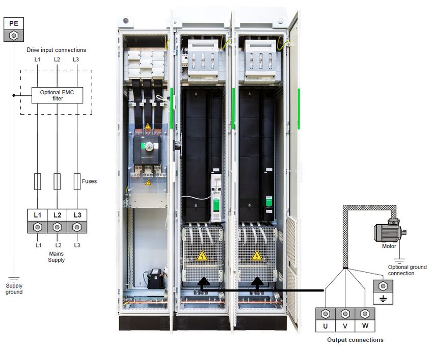
Copyright
The contents of this publication are believed to be correct at the time of printing. In the interests of a commitment to
a policy of continuous development and improvement, the manufacturer reserves the right to change the
specification of the product or its performance, or the contents of the guide, without notice.

All rights reserved. No parts of this guide may be reproduced or transmitted in any form or by any means, electrical
or mechanical including photocopying, recording or by an information storage or retrieval system, without
permission in writing from the publisher.

Copyright © January 2021 Nidec Control Techniques Ltd
Contents
1      Safety information .....................................................................................10
1.1         Warnings, Cautions and Notes ..............................................................................10
1.2         General information ................................................................................................10
1.3         Responsibility .........................................................................................................10
1.4         Compliance with regulations ..................................................................................10
1.5         Electrical hazards ...................................................................................................11
1.6         Stored electrical charge .........................................................................................11
1.7         Mechanical hazards ...............................................................................................11
1.8         Access to equipment ..............................................................................................11
1.9         Environmental limits ...............................................................................................11
1.10        Hazardous environments .......................................................................................11
1.11        Motor ......................................................................................................................12
1.12        Mechanical brake control .......................................................................................12
1.13        Adjusting parameters .............................................................................................12
1.14        Electromagnetic compatibility (EMC) .....................................................................12
1.15        Safe Torque Off ......................................................................................................12
2      Product information ..................................................................................13
2.1         Introduction ............................................................................................................13
2.2         Model number ........................................................................................................13
2.3         Nameplate description ...........................................................................................15
2.4         Ratings ...................................................................................................................16
2.5         Cubicle features .....................................................................................................18
3      Mechanical installation .............................................................................20
3.1         Safety information ..................................................................................................20
3.2         Planning the installation .........................................................................................22
3.3         Control terminal cover removal ..............................................................................24
3.4         Cubicle Dimensions ...............................................................................................26
3.5         Terminal size and torque settings ..........................................................................27
3.6         Routine maintenance .............................................................................................28
3.7         Cooling fan replacement ........................................................................................28
3.8         Storage ...................................................................................................................29
4      Electrical installation .................................................................................30
4.1         Power connections .................................................................................................31
4.2         Ground connections ...............................................................................................32
4.3         AC Supply requirements ........................................................................................34
4.4         Operation on IT (ungrounded) supplies .................................................................35
4.5         Ground connections ...............................................................................................36
4.6         Upstream protection ...............................................................................................36
4.7         Motor requirements ................................................................................................39
4.8         Output short circuit protection ................................................................................39
4.9         Motor overload protection ......................................................................................40
4.10        Motor cables ...........................................................................................................41
4.11        High-capacitance / reduced diameter cables .........................................................42
4.12        Output contactor .....................................................................................................43
4.13        Safe Torque Off ......................................................................................................43
4.14        Braking ...................................................................................................................43
4.15        Ground leakage ......................................................................................................44
4.16        Use of a residual current device (RCD) .................................................................44
4.17        Starts per hour .......................................................................................................44
4.18        Start-up time ...........................................................................................................44
4.19        Motor winding voltage ............................................................................................44
4.20        Star / Delta motor operation ...................................................................................45
4.21        External 24 V DC Supplies .....................................................................................45
4.22        Electromagnetic compatibility .................................................................................46

                                                                               DFS1/DFS2 Power Installation Guide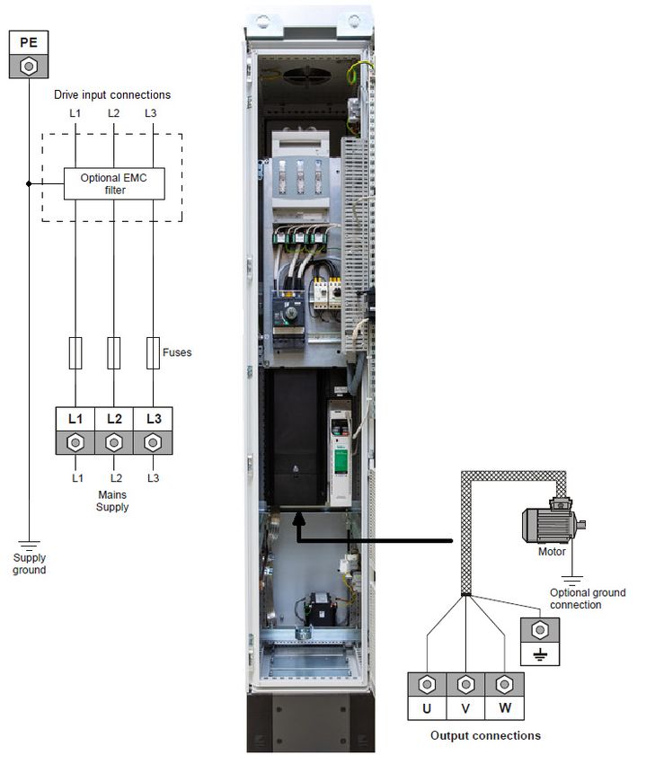
5          Technical data ............................................................................................53
       5.1             Drive technical data ............................................................................................... 53

DFS1/DFS2 Power Installation Guide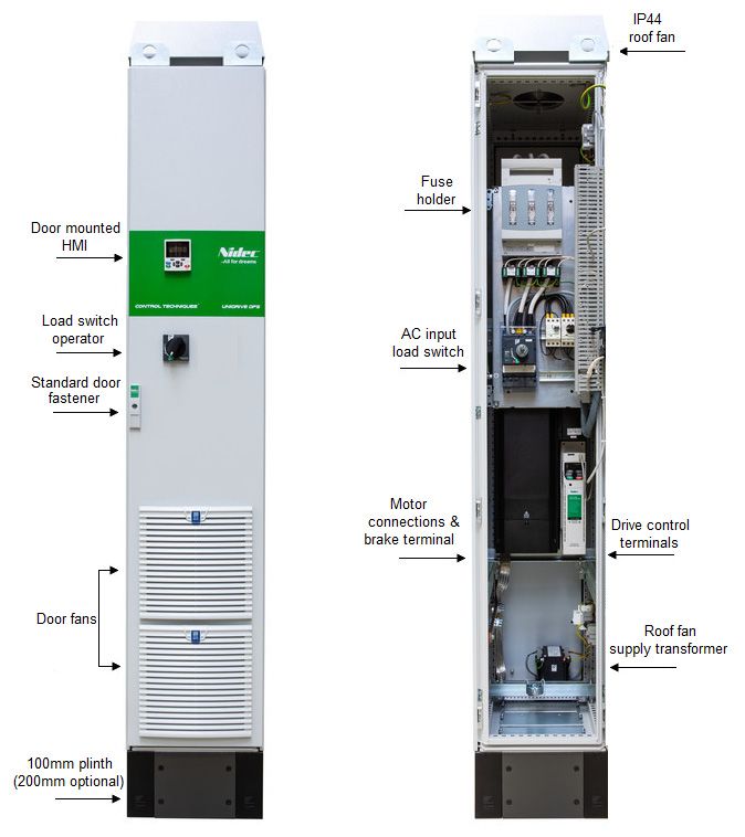
EU Declaration of Conformity
1. Product range
Drive Free Standing (DFS).
2. Name and address of the manufacturer
Nidec Netherlands B.V.
Kubus 155
3364 DG Sliedrecht
Postbus 300
3360 AH Sliedrecht
Netherlands
3. Responsibility
This declaration is issued under the sole responsibility of the manufacturer.
4. Object of the declaration
    Model No.         Interpretation                       Nomenclature aaaa - DFS b c d e f g h i
aaaa            Drive module range          Industrial drive = M700, M701, M702. Process drive = F300, F600
DFS             Format                      DFS = Drive Free Standing
b               Number of drives            1, 2
c               Current rating step         Any alphanumeric character: 1 – 9, A – Z
d               Voltage rating              4 = 400 V, 6 = 690 V
e               World Region                E = Europe, A = Americas
f               Input circuit               N = Rectifier - Single 6 pulse
g               Input switch                S = Load Switch (Standard)
h               Enclosure rating            A = IP23 – Air Cooled, C = IP54 – Air Cooled
                                            The model number may be followed by any combination of 10 digits
i               Options
                                            denoting customer options. The options do not affect the ratings.

5. Declaration
The object of the declaration is in conformity with the relevant European Union harmonisation
legislation.

Low Voltage Directive (2014/35/EU)
Electromagnetic Compatibility Directive (2014/30/EU)
Restriction of Hazardous Substances Directive (2011/65/EU).
6. References to the relevant harmonised standards used
The variable speed drive products listed above have been designed and manufactured in
accordance with the following European harmonised standards:
                                   Adjustable speed electrical power drive systems - Part 5-1: Safety requirements -
EN 61800-5-1:2007+A1:2017
                                   Electrical, thermal and energy
                                   Adjustable speed electrical power drive systems - Part 3: EMC requirements and
EN 61800-3: 2018
                                   specific test methods
                                   Electromagnetic compatibility (EMC) - Part 6-2: Generic standards - Immunity for
EN 61000-6-2: 2019
                                   industrial environments

6                                                                            DFS1/DFS2 Power Installation Guide
7. Responsible person

Jon Holman-White
Vice President of Research and Development
Nidec Control Techniques Ltd
Date: 20th May 2019
Newtown, Powys, UK.

These electronic drive products are intended to be used with appropriate motors, controllers,
electrical protection components and other equipment to form complete end products or
systems. Compliance with safety and EMC regulations depends upon installing and
configuring drives correctly, including using the specified input filters.
The drives must be installed only by professional installers who are familiar with
requirements for safety and EMC. Refer to the Product Documentation. An EMC data sheet is
available giving detailed information. The assembler is responsible for ensuring that the
product or system complies with all the relevant laws in the country where it is to be used.

DFS1/DFS2 Power Installation Guide                                                         7
EU Declaration of Conformity (Machinery Directive)
1. Product model
Unidrive-M and derivative products incorporating a Safe Torque Off (STO) function when used as a
safety component of a machine.
2. Name and address of the manufacturer
Nidec Control Techniques Ltd, The Gro, Newtown, Powys, SY16 3BE, UK

Registered in England and Wales, Company Reg. No. 0126885
Telephone: 00 44 1686 612300
E-mail: marketing.control techniques@mail.nidec.com
Web: www.controltechniques.com
3. This declaration is issued under the sole responsibility of the manufacturer.
4. Object of the declaration
    Model No.   Interpretation                         Nomenclature aaaa - bbc ddddde
                                 M600, M700, M701, M702, M708, M709, M750, M751, M753, M754, F300,
aaaa            Basic series
                                 F600, H300, E200, E300, HS70, HS71, HS72, M000, RECT
bb              Frame Size       03, 04, 05, 06, 07, 08, 09, 10, 11
c               Voltage Rating   1 = 100 V, 2 = 200 V, 4 = 400 V, 5 = 575 V, 6 = 690 V
ddddd           Current Rating   Example 01000 = 100 A
                                 A = 6P Rectifier + Inverter with internal choke, D = Inverter, E = 6P Rectifier +
e               Drive Format
                                 Inverter, T = 12P Rectifier + Inverter (external choke)

The model number may be followed by additional characters that do not affect the ratings.
5. The object of the declaration is in conformity with the relevant European Union
harmonisation legislation.
Machine Directive (2006/42/EC)
Electromagnetic Compatibility Directive (2014/30/EU)

EC type examination has been carried out by the following notified body:
 TUV Rheinland Industries Service GmbH                    EC type-examination certificate numbers:
 AM Grauen Stein
 D-51105 Köln                                             01/205/5270.02/17 dated 2017-08-28
 Germany

Notified body identification number: 0035

Only the Safe Torque Off function may be used for a safety function of a machine. None of the other
functions of the drive may be used to carry out a safety function. The object of the declaration is in
conformity with the relevant European Union harmonisation legislation.

8                                                                       DFS1/DFS2 Power Installation Guide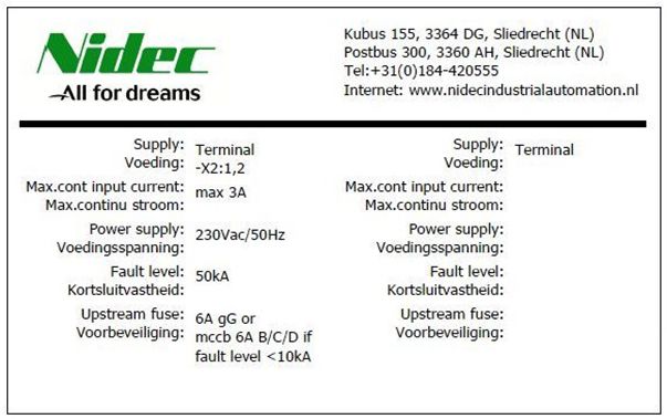
6. References to the relevant harmonised standards used
The variable speed drive products listed above have been designed and manufactured in
accordance with the following European harmonized standards:

                               Adjustable speed electrical power drive systems - Part 5-2: Safety requirements -
EN 61800-5-2:2016
                               Functional
EN 61800-5-1:2016              Adjustable speed electrical power drive systems - Part 5-1: Safety requirements -
(in extracts)                  Electrical, thermal and energy
                               Adjustable speed electrical power drive systems - Part 3: EMC requirements and
EN 61800-3: 2004+A1:2012
                               specific test methods
                               Safety of Machinery, Safety-related parts of control systems, General principles
EN ISO 13849-1:2015
                               for design
EN 62061:2005 + AC:2010 +      Safety of Machinery, Functional safety of safety related electrical, electronic and
A1:2013 + A2:2015              programmable electronic control systems
                               Functional safety of electrical/electronic/programmable electronic safety-related
IEC 61508 Parts 1 - 7:2010
                               systems

7. Signed for and behalf of:
 Person authorised to complete the technical file: P. Knight
                                                   Conformity Engineer
                            DoC authorised by: Jon Holman-White
                                                   Vice President of Research
                                                   and Development
                                           Date: 19th November 2018
                                          Place: Newtown, Powys, UK

DFS1/DFS2 Power Installation Guide                                                                                 9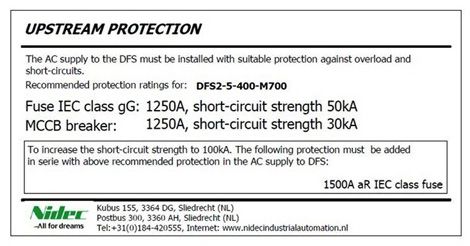
1           Safety information
1.1         Warnings, Cautions and Notes

            A Warning contains information which is essential for avoiding a safety hazard.
 WARNING

            A Caution contains information which is necessary for avoiding a risk of damage to the
            product or other equipment.
  CAUTION

 NOTE       A Note contains information, which helps to ensure correct operation of the product.

1.2         General information
This guide applies to products which control electric motors either directly (drives) or indirectly
(controllers, option modules and other auxiliary equipment and accessories). In all cases the hazards
associated with powerful electrical drives are present, and all safety information relating to drives and
associated equipment must be observed.
Specific warnings are given at the relevant places in this guide.
Drives and controllers are intended as components for professional incorporation into complete
systems. If installed incorrectly they may present a safety hazard. The drive uses high voltages and
currents, carries a high level of stored electrical energy, and is used to control equipment which can
cause injury. Close attention is required to the electrical installation and the system design to avoid
hazards either in normal operation or in the event of equipment malfunction. System design,
installation, commissioning/start-up and maintenance must be carried out by personnel who have the
necessary training and competence. They must read this safety information and this guide carefully.

1.3         Responsibility
It is the responsibility of the installer to ensure that the equipment is installed correctly with regard to
all instructions given in this guide. They must give due consideration to the safety of the complete
system, so as to avoid the risk of injury both in normal operation and in the event of a fault or of
reasonably foreseeable misuse.
The manufacturer accepts no liability for any consequences resulting from inappropriate, negligent or
incorrect installation of the equipment.

1.4         Compliance with regulations
The installer is responsible for complying with all relevant regulations, such as national wiring
regulations, accident prevention regulations and electromagnetic compatibility (EMC) regulations.
Particular attention must be given to the cross-sectional areas of conductors, the selection of fuses
or other protection, and protective ground (earth) connections.
This guide contains instructions for achieving compliance with specific EMC standards.
All machinery to be supplied within the European Union in which this product is used must comply
with the following directives:
2006/42/EC Safety of machinery.
2014/30/EU: Electromagnetic Compatibility.

10                                                                  DFS1/DFS2 Power Installation Guide
1.5 Electrical hazards
The voltages used in the drive can cause severe electrical shock and/or burns, and could be lethal.
Safety information
Extreme care is necessary at all times when working with or adjacent to the drive. Hazardous voltage
may be present in any of the following locations:
• AC and DC supply cables and connections
• Output cables and connections
• Many internal parts of the drive, and external option units
Unless otherwise indicated, control terminals are single insulated and must not be touched.
The supply must be disconnected by an approved electrical isolation device before gaining access to
the electrical connections.
The STOP and Safe Torque Off functions of the drive do not isolate dangerous voltages from the
output of the drive or from any external option unit.
Product information
The drive must be installed in accordance with the instructions given in this guide. Failure to observe
the instructions could result in a fire hazard.
1.6 Stored electrical charge
The drive contains capacitors that remain charged to a potentially lethal voltage after the AC supply
has been disconnected. If the drive has been energized, the AC supply must be isolated at least ten
minutes before work may continue.
1.7 Mechanical hazards
Mechanical installation
Careful consideration must be given to the functions of the drive or controller which might result in a
hazard, either through their intended behaviour or through incorrect operation due to a fault. In any
application where a malfunction of the drive or its control system could lead to or allow damage, loss
or injury, a risk analysis must be carried out, and where necessary, further measures taken to reduce
the risk - for example, an over-speed protection device in case of failure of the speed control, or a
fail-safe mechanical brake in case of loss of motor braking.
With the sole exception of the Safe Torque Off function, none of the drive functions must be
used to ensure safety of personnel, i.e. they must not be used for safety-related functions.
The Safe Torque Off function may be used in a safety-related application. The system designer is
responsible for ensuring that the complete system is safe and designed correctly according to the
Electrical installation
relevant safety standards.
The design of safety-related control systems must only be done by personnel with the required training
and experience. The Safe Torque Off function will only ensure the safety of a machine if it is correctly
incorporated into a complete safety system. The system must be subject to a risk assessment to
confirm that the residual risk of an unsafe event is at an acceptable level for the application.
1.8 Access to equipment
Access must be restricted to authorized personnel only. Safety regulations which apply at the place
of use must be complied with.
1.9 Environmental limits
Technical data
Instructions in this guide regarding transport, storage, installation and use of the equipment must be
complied with, including the specified environmental limits. This includes temperature, humidity,
contamination, shock and vibration. Drives must not be subjected to excessive physical force.
1.10 Hazardous environments
The equipment must not be installed in a hazardous environment (i.e. a potentially explosive
environment).
DFS1/DFS2 Power Installation Guide 111.11 Motor The safety of the motor under variable speed conditions must be ensured. To avoid the risk of physical injury, do not exceed the maximum specified speed of the motor. Low speeds may cause the motor to overheat because the cooling fan becomes less effective, causing a fire hazard. The motor should be installed with a protection thermistor. If necessary, an electric forced vent fan should be used. The values of the motor parameters set in the drive affect the protection of the motor. The default values in the drive must not be relied upon. It is essential that the correct value is entered in the Motor Rated Current parameter. 1.12 Mechanical brake control Any brake control functions are provided to allow well co-ordinated operation of an external brake with the drive. While both hardware and software are designed to high standards of quality and robustness, they are not intended for use as safety functions, i.e. where a fault or failure would result in a risk of injury. In any application where the incorrect operation of the brake release mechanism could result in injury, independent protection devices of proven integrity must also be incorporated. 1.13 Adjusting parameters Some parameters have a profound effect on the operation of the drive. They must not be altered without careful consideration of the impact on the controlled system. Measures must be taken to prevent unwanted changes due to error or tampering. 1.14 Electromagnetic compatibility (EMC) Installation instructions for a range of EMC environments are provided in the relevant Power Installation Guide. If the installation is poorly designed or other equipment does not comply with suitable standards for EMC, the product might cause or suffer from disturbance due to electromagnetic interaction with other equipment. It is the responsibility of the installer to ensure that the equipment or system into which the product is incorporated complies with the relevant EMC legislation in the place of use. 1.15 Safe Torque Off The Unidrive M700 / M701 has a single channel Safe Torque Off, whereas the Unidrive M702 has a dual channel STO. The Safe Torque Off function provides a means for preventing the drive from generating torque in the motor, with a very high level of integrity. It is suitable for incorporation into a safety system for a machine. It is also suitable for use as a conventional drive enable input. Machinery Applications The Safe Torque Off function has been independently assessed by Notified Body, TüV Rheinland for use as a safety component of a machine: Prevention of unintended motor operation: The safety function “Safe Torque Off” can be used in applications up to Cat 4, PL e according to EN ISO 13849-1, SIL 3 according to EN 61800-5-2/ EN 62061/ IEC 61508 and in lift applications according to EN 81-1 and EN 81-2. TüV certificate No. 01.205/5270.02/17 Date: 28-08-2017 For further details consult the M700, M701 M702 Control User Guide, CT part No. 0478-0353. 12 DFS1/DFS2 Power Installation Guide
2                Product information

                                                                                                                                                                      Safety information
2.1              Introduction
This guide provides the information necessary to install the following cubicle models:
DFS 1
DFS 2
This guide focuses on the cubicle power section, for example: electrical installation of the supply /
motor cables and mechanical installation of the cubicle.
The drives are housed in a compact IP23 or IP54 enclosure. A water-cooled option is available.
A wide range of options are available including EMC filters and kWh meters.

                                                                                                                                                                      Product information
This guide focuses on the drive power section, for example: electrical installation of the supply /
motor cables and mechanical installation of the drive.
For information about the cubicle control section, for example: parameter set up information, control
and encoder connections please refer to the M700, M701 M702 Control User Guide CT part
No. 0478-0353.

2.2              Model number
The model number for the DFS product range is formed as illustrated below:
Figure 2-1          Model numbers

                                                                                                                                                                      Mechanical installation
                                                                                                                       Input       Enclosure
                             Drive range     Format              Drive Specification               Configuation                                Cubicle options code
                                                                                                                      switch         rating

                               M70x          DFS            1            9             4           E          N         S             A            10000000

                                      Free standing drive
                                                                                                                                                 Options(See
                                                                                            World region:         Input switch:                  table 2-1)
    Drive range:                      Number of parallel drives in
                                                                                            E= Europe             S= Load switch
    M70x Industrial drive             a cubicle
                                                                                            A = Americas
    F300 Process drive
    F600 Pump drive
                                      Current rating step
                                                                                                                      Enclosure rating:
                                                                                            Input circuit
                                                                                                                      A= IP23
                                                                                            N = Rectifier -           C= IP54 - Filters, through panel
                                      Supply voltage:

                                                                                                                                                                      Electrical installation
                                                                                            Single 6 pulse            mounted heatskinks, roof mounted
                                      4=400 V; 6=690 V                                                                exhaust grill
                                                                                                                      W= Water cooled heat exchanger
                                                                                                                      (IP55)

Table 2-1 Options
                            Option                                                         Description                                    Selection Rule
IP23                                                                 A = IP23 (Standard)
IP54                                                                 B = IP54                                                             Choose A, B or W
IP55 - Water Cooled                                                  W = Water cooled heat exchanger
EMC Filter                                                                                                                                          N/A
                                                                                                                                                                      Technical data

Remove internal EMC filter                                           Remove internal EMC filter                                                     N/A
Remove MOV protection                                                Remove MOV protection                                                          N/A
Speed-controlled roof fan                                            Cabinet temperature controlled roof fan                                        N/A
Plinth 200 mm                                                        Standard plinth is 100 mm                                                      N/A
180° door hinges                                                     Alternative hinge for improved access                                          N/A

DFS1/DFS2 Power Installation Guide                                                                                                                               13
Option Description Selection Rule
Cylinder lock with key Extra cubicle security N/A
A - Undervoltage release coil 230 VAC Main switch with 230 VAC (MN)
If release coil
B - Undervoltage release coil 24 VAC Main switch with 24 VAC (MN) needed, choose A,
B, C or D
C - Shunt trip voltage release coil 230 VAC Main switch with 230 VAC (MX)
D - Shunt trip voltage release coil 24 VAC Main switch with 24 VAC (MX)
A - kWh meter Conventional (IP54) with CTs (non MID)
If kWh meter
B - kWh meter Modbus RTU with CTs (non MID)
needed, choose A,
C - kWh meter Profibus B, C or D
with CTs (non MID)
(Not available with 690 V)
D - kWh meter Ethernet with CTs (non MID)
In combination with A, B, C or D kWh
kWh meter pulse contacts See description
meters
Provision for external 24 V backup power
24 V back-up supply wiring N/A
supply
Supply and wiring of two auxiliary contacts
Auxiliary contacts main switch N/A
on main switch
Includes plinth 100 mm both cable plates
Rittal integrated empty incomer 400 mm N/A
mounted to DFS
Back plate empty incomer N/A
Emergency stop push button Red push button on door N/A
Air Freight Additional Packaging for DFS1
Pallet, Straps, Carton and Labour N/A
and 1
When ordering a DFS drive, options can be selected using an on-line configurator tool. Alternatively,
contact the local Control Techniques drives sales office for further information. The standard options
are summarised in Table 2-1.
NOTE
Cubicle options code is generated by an on-line configurator.
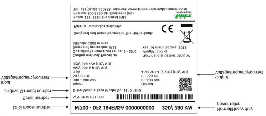
14 DFS1/DFS2 Power Installation Guide2.3 Nameplate description
Figure 2-2 Typical drive rating label
Safety information
DFS model number Normal/heavy duty
power rating
Serial number
Unidrive M model number
Input
Voltage/frequency/current Output
Voltage/frequency/current
Product information
Figure 2-3 Auxiliary supply rating label
Mechanical installation
Figure 2-4 Upstream protection warning label
Electrical installation
Technical data
DFS1/DFS2 Power Installation Guide 152.4 Ratings
Table 2-2 400 V and 690 V ratings
Output
Motor power
Supply Supply Output power at Peak Output
at 460 V
Model voltage current current 400 V current
(ND/HD)
V A A (ND/HD) A
hp
kW
xxxx-DFS1G4EN 400 155 155/134 75/55 100/100 172
xxxx-DFS1H4EN 400 177 184/157 90/75 150/125 202
xxxx-DFS1J4EN 400 232 221/200 110/90 150/150 243
xxxx-DFS1K4EN 400 267 266/224 132/110 200/150 293
xxxx-DFS1L4EN 400 332 320/270 160/132 250/200 352
xxxx-DFS1M4EN 400 397 361/320 200/160 300/250 397
xxxx-DFS1N4EN 400 449 437/377 225/185 350/300 481
xxxx-DFS1P4EN 400 492 487/417 250/200 400/350 536
xxxx-DFS1Q4EN 400 539 507/464 280/250 450/400 558
xxxx-DFS2L4EN 400 631 608/513 320/264 500/400 704
xxxx-DFS2M4EN 400 657 686/608 400/320 600/500 794
xxxx-DFS2N4EN 400 853 830/716 450/370 700/600 962
xxxx-DFS2P4EN 400 935 925/792 500/400 800/700 1072
xxxx-DFS2Q4EN 400 1024 963/882 560/500 900/800 1116
xxxx-DFS166EN 690 83 86/63 75/55 100/75 95
xxxx-DFS176EN 690 104 108/86 90/75 125/100 119
xxxx-DFS186EN 690 149 125/104 110/90 150/125 138
xxxx-DFS196EN 690 171 155/131 132/110 175/150 171
xxxx-DFS1A6EN 690 202 172/150 160/132 200/175 189
xxxx-DFS1B6EN 690 225 197/178 185/160 250/200 217
xxxx-DFS1C6EN 690 256 225/210 200/185 250/250 248
xxxx-DFS1D6EN 690 302 275/238 250/200 300/250 303
xxxx-DFS1E6EN 690 329 305/263 280/250 400/300 336
xxxx-DFS2A6EN 690 384 327/285 320/264 400/350 378
xxxx-DFS2B6EN 690 427 374/338 370/320 500/400 434
xxxx-DFS2C6EN 690 486 428/399 400/370 500/500 496
xxxx-DFS2D6EN 690 574 523/452 500/400 600/500 606
xxxx-DFS2E6EN 690 625 580/500 560/500 800/600 672
NOTE
xxxx denotes F300, F600, M700, M701 or M702.
NOTE
Output current and power ratings are shown as Normal Duty/ Heavy Duty For an explanation of
Normal and Heavy-Duty ratings, refer to the M700, M701, M702 Control User Guide (CT part
number: 0478-0353).
NOTE
M70x data based on Heavy Duty ratings. F300/F600 data based on Normal Duty ratings.
16 DFS1/DFS2 Power Installation GuideNOTE
M70x data based on Heavy Duty ratings. F300/F600 data based on Normal Duty ratings.
Safety information
Table 2-3 Protective ground cable ratings
Input phase conductor size Minimum ground conductor size
> 35 mm² Half of the cross-sectional area of the input phase conductor
Typical short-term overload limits
The maximum percentage overload limit changes depending on the selected motor. Variations in
motor rated current, motor power factor and motor leakage inductance all result in changes in the
maximum possible overload. Typical values are shown in the table below:
Table 2-4 Typical overload limits
Product information
RFC from Open loop Open loopfrom
Operating mode RFC from cold
100 % from cold 100 %
Normal Duty overload with motor rated
110 % for 165 s 110 % for 9 s 110 % for 165 s 110 % for 9 s
current = drive rated current
Heavy Duty overload with motor rated
175 % for 42 s 175 % for 5 s 150 % for 60 s 150 % for 7 s
current = drive rated current
Generally, the drive rated current is higher than the matching motor rated current allowing a higher
level of overload than the default setting.
The time allowed in the overload region is proportionally reduced at very low output frequency on
Mechanical installation
some drive ratings.
NOTE
The maximum overload level which can be attained is independent of the speed.
Output current
The continuous output current ratings given on the rating label are for maximum 35 °C (95 °F),
1000 m altitude and 2 kHz switching frequency. Derating is required for higher switching frequencies,
ambient temperatures > 40 °C (104 °F). For further information, refer to Chapter 5.1 Drive technical
data on page 53.
Input current
Electrical installation
The input current is affected by the supply voltage and impedance. The input current given on the
rating label is the typical input current and is stated for a balanced supply.
Technical data
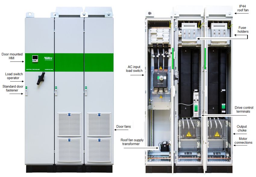
DFS1/DFS2 Power Installation Guide 172.5 Cubicle features Figure 2-5 Features of the size 1 cubicle 18 DFS1/DFS2 Power Installation Guide
Figure 2-6   Features of the size 2 cubicle

                                                                                                      Safety information
                                                                                                      Product information
                                                                                                      Mechanical installation
NOTE
E-plan drawings, which contain parts lists and electrical schematic diagrams for all the DFS frame
sizes are available on Support Suite.

                                                                                                      Electrical installation
                                                                                                      Technical data

DFS1/DFS2 Power Installation Guide                                                               19
3 Mechanical installation
3.1 Safety information
Follow the instructions
The mechanical and electrical installation instructions must be adhered to. Any questions
or doubt should be referred to the supplier of the equipment. It is the responsibility of the
WARNING owner or user to ensure that the installation of the drive and any external option unit, and
the way in which they are operated and maintained, comply with the requirements of the
Health and Safety at Work Act in the United Kingdom or applicable legislation and
regulations and codes of practice in the country in which the equipment is used.
Stored charge
The drive contains capacitors that remain charged to a potentially lethal voltage after the
AC supply has been disconnected. If the drive has been energized, the AC supply must
WARNING be isolated at least ten minutes before work may continue.
Normally, the capacitors are discharged by an internal resistor. Under certain, unusual
fault conditions, it is possible that the capacitors may fail to discharge, or be prevented
from being discharged by a voltage applied to the output terminals. If the drive has failed
in a manner that causes the display to go blank immediately, it is possible the capacitors
will not be discharged. In this case, consult Nidec Industrial Automation or their authorized
distributor.
Competence of the installer
The drive must be installed by professional assemblers who are familiar with the
requirements for safety and EMC. The assembler is responsible for ensuring that the end
WARNING product or system complies with all the relevant laws in the country where it is to be used.
Enclosure
The drive is intended to be mounted in an enclosure which prevents access except by
trained and authorized personnel, and which prevents the ingress of contamination. It is
WARNING designed for use in an environment classified as pollution degree 2 in accordance with
IEC 60664-1. This means that only dry, non-conducting contamination is acceptable.
Hazardous areas
The drive must not be installed in a classified hazardous area unless it is installed in an
approved enclosure and the installation in certified.
WARNING
Protection of equipment prior to installation
If the equipment is not to be installed immediately, it must be protected from moisture and
dust.
CAUTION
The equipment is delivered wrapped in plastic to protect it from mechanical damage. It is
recommended that wrapping is left in place until installation.
20 DFS1/DFS2 Power Installation Guide3.1.1 Lifting and Handling
NOTE
The information in this section is also provided on a laminated sheet fixed to the outside of the
Safety information
enclosure. It is intended to be read by the personnel responsible for lifting, handling and transporting
the drive.
Lifting and handling
Always lift the drive by the lifting lugs.
The drives are not supplied with lifting lugs. These must be fitted to the top of the enclosure
WARNING
by the installer.
Insert shackles into the eye bolts. Ensure that the angle of each lifting rope is greater than
45°, as shown in Figure 3-1.
Product information
Figure 3-1 Lifting the cubicle
Use the lifting eyebolts attached
to the top of the enclosure
Mechanical installation
Arrow indicates the lifting point/
direction of the enclosure
Insert the shackles into the
Electrical installation
eyebolts. Ensure the angle of
each lifting rope is ≥ 45°
The cubicle is disproportionally heavy at the top and must be properly secured to prevent
it from overbalancing and falling during installation.
When transporting the equipment by fork lift truck, place the cubicle on a rigid pallet and
WARNING
secure it in place.
Multiple bayed enclosures cannot be transported this way.
Technical data
The maximum weight of the cubicles are shown in Table 3-1.
Table 3-1 Maximum cubicle weight
Size Model kg lb
DFS1 All variants 300 661
DFS2 All variants 720 1587
DFS1/DFS2 Power Installation Guide 21Figure 3-2 Transporting the cubicle
3.2 Planning the installation
The following considerations must be made when planning the installation:
3.2.1 Access
Access must be restricted to authorized personnel only. Safety regulations which apply at the place
of use must be complied with.
3.2.2 Environmental protection
The DFS drives are offered with a choice of two Ingress Protection (IP) ratings:
IP23: Protection against fingers or similar objects larger than 12.5 mm. Protection from water falling
as a spray at any angle up to 60° from the vertical.
IP54: Protection against ingress of dust is not entirely prevented but must not enter in quantities that
may interfere with operation of the equipment. Protection from water splashing against the enclosure
from any direction.
The drive enclosure protects the internal components from:
• Moisture, including dripping water or spraying water and condensation. An anti-condensation
heater may be required, which must be switched off when the drive is running.
• Contamination with electrically conductive material
• Contamination with any form of dust which may restrict the fan, or impair airflow over various
components
• Temperature beyond the specified operating and storage ranges
• Corrosive gasses
NOTE
During installation it is recommended that the vents on the drive are covered to prevent debris
(e.g. wire off-cuts) from entering the cubicle.
3.2.3 Cooling
The heat produced by the internal components must be removed without its specified operating
temperature being exceeded. Note that a sealed enclosure gives much reduced cooling compared
with a ventilated one and may need to be larger and/or use internal air circulating fans.
3.2.4 Fire protection
The enclosure is classified as a Fire Enclosure within the meaning of IEC 62109-1. It surrounds the
internal parts and is intended to minimize the spread of fire or flaming materials from within.
22 DFS1/DFS2 Power Installation Guide3.2.5 Electromagnetic compatibility
Variable speed drives are powerful electronic circuits which can cause electromagnetic interference if
not installed correctly with careful attention to the layout of the wiring.
Safety information
Some simple routine precautions can prevent disturbance to typical industrial control equipment.
If it is necessary to meet strict emission limits, or if it is known that electromagnetically sensitive
equipment is located nearby, then full precautions must be observed. In-built into the drive, is an
internal EMC filter, which reduces emissions under certain conditions. If these conditions are
exceeded, then the use of an external EMC filter may be required at the drive inputs, which must be
located very close to the drives. Space must be made available for the filters and allowance made for
carefully segregated wiring. For further details relating to EMC, refer to the EMC data sheet,
CT part number 0478-0575.
3.2.6 Electrical safety
Product information
The installation must be safe under normal and fault conditions. Electrical installation instructions are
given in Chapter 4 Electrical installation on page 30.
Hot surfaces
Care must be taken when opening the cubicle door as some components may be very hot
to touch even after the 10 minutes discharge time.
WARNING
Component IP ratings
Mechanical installation
The internal cubicle components are rated to IP20. This must be taken into consideration
when the doors are opened.
CAUTION
Electrical installation
Technical data
DFS1/DFS2 Power Installation Guide 233.3 Control terminal cover removal 3.3.1 Removing the drive control terminal cover The Unidrive M drive control terminals are fitted with a terminal cover. The terminal cover must be removed to gain access to the control terminals. NOTE Refer to the relevant control user guide for details on the control terminal layout, functionality and option modules. Figure 3-3 Location and identification of terminal cover 24 DFS1/DFS2 Power Installation Guide
3.3.2        Removal of finger-guard breakouts
To remove the finger-guards place the finger-guard on a flat solid surface and knock out the finger
guards using a hammer. The breakout can be removed by grasping it with pliers and twisting it off.

                                                                                                        Safety information
Once all break-outs have been removed, remove any flash/sharp edges. See Figure 3-4.
Figure 3-4    Removing the finger-guard breakouts

                                                                                                        Product information
                                                                                                        Mechanical installation
             Grommets
             Grommets should be installed in the power terminal apertures to help restrict the spread
             of fire in the event of a major internal failure.
  WARNING

Table 3-2     Grommet kits

                                                                                                        Electrical installation
                        Drive module size                         Part number            Image

Frame size 8 - kit of 8 single entry grommets                      3470-0089

Frame size 8- kit of 8 double entry grommets                       3470-0090

Frame size 9, 10 and 11 – kit of 8 double entry grommets           3470-0107
                                                                                                        Technical data

DFS1/DFS2 Power Installation Guide                                                                25
3.4 Cubicle Dimensions
Figure 3-5 Dimensions of the DFS1 cubicle
Width Depth Height Plinth height Roof fan height
Cubicle type b c e
a d
IP23 IP54 IP23 IP23 IP54
DFS1 400 600 725 2000 100 or 200 180 65
26 DFS1/DFS2 Power Installation Guide3.4.1 Cubicle dimensions
Figure 3-6 Dimensions of the DFS2 cubicle
Safety information
Product information
Mechanical installation
Width Depth Height Plinth height Roof fan height
Cubicle type b c e
Electrical installation
a d
IP23 IP54 IP23 IP23 IP54
DFS2 1200 600 725 2000 100 or 200 180 65
3.5 Terminal size and torque settings
Table 3-3 Drive control and relay terminal data
Terminal Connection size Torque setting
AC supply M10 lug 15 Nm (11.1 lb ft)
Drive module Motor output terminals 1 x M10 x 17 AF Nut 15 Nm (11.1 lb ft)
Earth (Ground) terminals 1 x M10 x 17 AF Nut 15 Nm (11.1 lb ft)
Technical data
Output sharing choke bus bar
1 x 11 mm hole 10 Nm (7.38 lb ft)
connections
Mains isolation switch 3 x M10 x 27.5 AF Nut 20 Nm (14.76 lb ft)
Control terminals Plug-in terminal block 0.2 Nm (0.4 lb ft)
Status relay terminals Plug-in terminal block 0.5 Nm (0.4 lb ft)
DFS1/DFS2 Power Installation Guide 27Stored charge
The drive contains capacitors that remain charged to a potentially lethal voltage after the
AC supply has been disconnected. If the drive has been energized, the AC supply must
WARNING be isolated at least ten minutes before work may continue.
Normally, the capacitors are discharged by an internal resistor. Under certain, unusual
fault conditions, it is possible that the capacitors may fail to discharge, or be prevented
from being discharged by a voltage applied to the output terminals. If the drive has failed
in a manner that causes the display to go blank immediately, it is possible the capacitors
will not be discharged. In this case, consult Nidec Industrial Automation or their authorized
distributor.
3.6 Routine maintenance
The cubicle should be installed in a cool, clean, well ventilated location. Contact of moisture and dust
with the drive should be prevented.
Regular checks of the following should be carried out to ensure drive / installation reliability are
maximized:
Environment
Ambient temperature Ensure the enclosure temperature remains at or below maximum specified.
Check that the drive module heatsinks and cooling fans are not gathering dust.
Dust This includes the roof fans and the filters in the door. The lifetime of the lfan is reduced
in dusty environments.
Moisture Ensure the cubicle shows no signs of condensation.
Enclosure
Enclosure door filters Ensure filters are not blocked and that air is free to flow.
Electrical
Screw connections Ensure all screw terminals remain tight.
Ensure all crimp terminals remains tight – check for any discoloration which could
Crimp terminals
indicate overheating.
Cables Check all cables for signs of damage.
3.7 Cooling fan replacement
Refer to the drive module Power Installation guides for details of how to replace the drive module
cooling fans in the event of failure.
28 DFS1/DFS2 Power Installation Guide3.8 Storage
The storage conditions are as follows:
Safety information
Storage temperature: 5 °C to 55 °C
Maximum humidity: 95 % non-condensing at 35 °C.
Maximum storage time: 2 years.
Storage time
Electrolytic capacitors in any electronic product have a finite storage period after which
they require reforming or replacing.
CAUTION
The drive modules have a maximum storage time of 2 years, after which the equipment
should be powered up for a minimum of 1 hour to reform the capacitors. The equipment
can then be stored for a further 2 years.
Product information
Mechanical installation
Electrical installation
Technical data
DFS1/DFS2 Power Installation Guide 294 Electrical installation
Electric shock risk
The voltages present in the following locations can cause severe electric shock and may
be lethal:
WARNING
AC supply cables and connections
DC and brake cables, and connections
Output cables and connections
Many internal parts of the drive, and external option units
Unless otherwise indicated, control terminals are single insulated and must not be
touched.
Isolation device
The AC and / or DC power supply must be disconnected from the drive using an approved
isolation device before any cover is removed from the drive or before any servicing work
WARNING is performed.
STOP function
The STOP function does not remove dangerous voltages from the drive, the motor or any
external option units.
WARNING
Safe Torque Off function
The Safe Torque Off function does not remove dangerous voltages from the drive,
the motor or any external option units.
WARNING
Stored charge
The drive contains capacitors that remain charged to a potentially lethal voltage after the
AC and / or DC power supply has been disconnected. If the drive has been energized,
WARNING the AC and / or DC power supply must be isolated at least ten minutes before work may
continue. Normally, the capacitors are discharged by an internal resistor. Under certain,
unusual fault conditions, it is possible that the capacitors may fail to discharge or be
prevented from being discharged by a voltage applied to the output terminals. If the drive
has failed in a manner that causes the display to go blank immediately, it is possible the
capacitors will not be discharged. In this case, consult Nidec Industrial Automation or
their authorized distributor.
Permanent magnet motors
Permanent magnet motors generate electrical power if they are rotated, even when the
supply to the drive is disconnected. If that happens then the drive will become energized
WARNING
through its motor terminals. If the motor load is capable of rotating the motor when the
supply is disconnected, then the motor must be isolated from the drive before gaining
access to any live parts.
30 DFS1/DFS2 Power Installation GuideSafety information Product information Mechanical installation Electrical installation Technical data
31
DFS1 Power connections
Power connections
DFS1/DFS2 Power Installation Guide
Figure 4-1
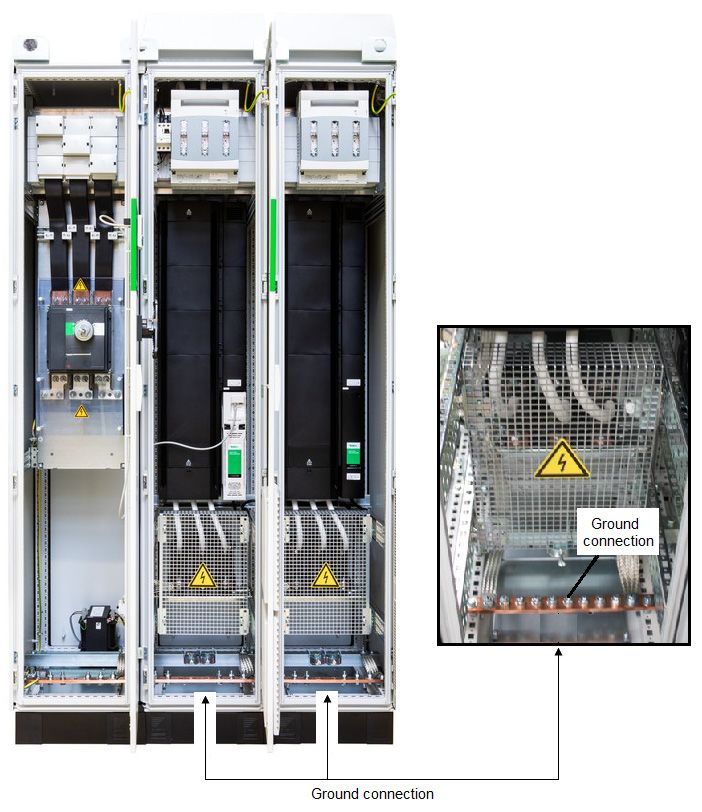
4.1Figure 4-2 DFS2 power connections
4.2 Ground connections
The ground loop impedance must conform to the requirements of local safety regulations.
The drive must be grounded by a connection capable of carrying the prospective fault
current until the protective device (fuse, etc.) disconnects the AC supply.
WARNING The ground connections must be inspected and tested at appropriate intervals.
The cubicle must be connected to the system ground of the AC supply. The ground wiring must
conform to local regulations and codes of practice.
The supply and motor ground connections are made using the ground busbar shown in Figure 4-3
and Figure 4-4.
32 DFS1/DFS2 Power Installation GuideSafety information Product information Mechanical installation Electrical installation Technical data
33
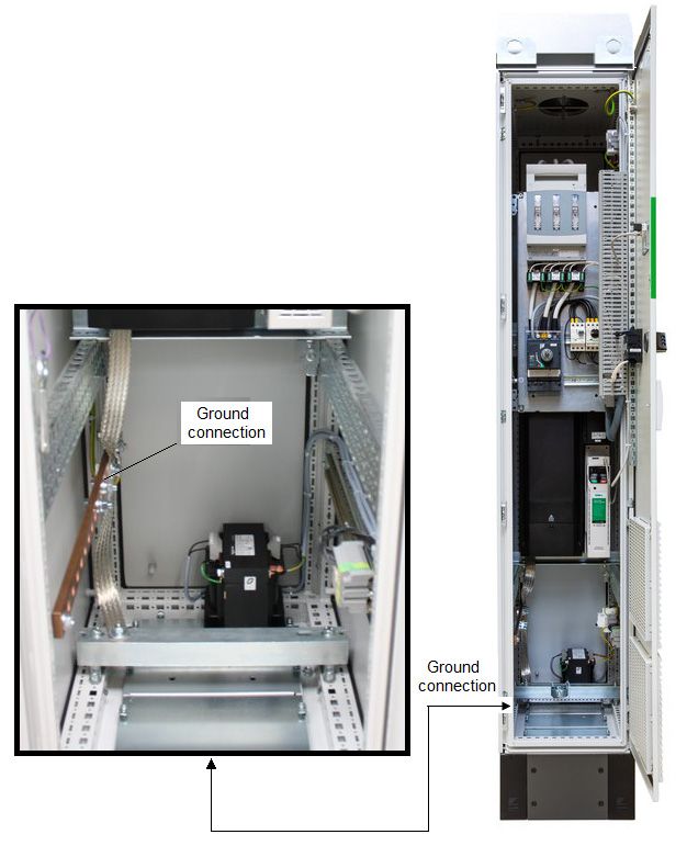
DFS1 ground connections
DFS1/DFS2 Power Installation Guide
Figure 4-3Figure 4-4 DFS2 ground connections 4.3 AC Supply requirements The DFS drives are suitable for use on any supply type: TN-S, TN-C-S, TT and IT. The AC supply should comply with the limits shown in Table 4-1. 34 DFS1/DFS2 Power Installation Guide
Table 4-1      AC supply specification
            Parameter                                                     Rating

                                                                                                                         Safety information
Voltage                           380 V to 480 V ±10 %                       500 V to 690 V ±10 %
No of phases                      3
Supply frequency                  45 to 66 Hz
Supply type                       TN-S, TN-C-S, TT, IT
Overvoltage category              OVC III (according to IEC 60664-1)1
Impulse voltage rating            4 kV for 400 V, 6 kV for 690 V drives
                                  2 % negative phase sequence (equivalent to 3 % voltage imbalance between
Maximum supply imbalance
                                  phases).

      1. For installations where the equipment is installed at the origin of the supply, additional over-voltage

                                                                                                                         Product information
      suppression (transient voltage surge suppression) must be provided to reduce the overvoltage category
      from OVC IV to OVC III.

              Auxiliary transformer tap setting
              Before powering up the drive, it is important to check that the auxiliary transformer tapping
              has been set correctly. Wrong selection could result in damage to transformer and the roof
 WARNING      fans.

4.4           Operation on IT (ungrounded) supplies

                                                                                                                         Mechanical installation
              Operation on IT (ungrounded) supplies
              Unusual hazards can occur on IT (ungrounded supplies).
              A ground (earth) fault in the incoming supply has no effect. The drive will continue to run.
  WARNING
              However, the phase to phase voltage will appear between two of the supply terminals and
              ground (Earth). On a 690 V supply, this will stress the insulation.
              A ground (earth) fault in the motor circuit may not cause the drive to trip. If the motor
              is required to continue to run with a ground fault in its circuit, then an input isolating
              transformer must be provided. If an EMC filter is required, it must be located on the
              primary side of the isolating transformer.
              The following measures must be taken:

                                                                                                                         Electrical installation
              Additional, independent motor ground fault protection must be provided.
              EMC filters must not be used
              The internal EMC filter inside the drive module must be disconnected1.
      1. Disconnection of the internal EMC filter on frame size 11E is only possible at the factory. This must be
      specified when ordering.
                                                                                                                         Technical data

DFS1/DFS2 Power Installation Guide                                                                                  35
4.5 Ground connections
Ground connections
The equipment must be grounded (earthed). The wiring must conform to local regulations
and codes of practice. This is the responsibility of the installer.
WARNING
The ground loop impedance must conform to the requirements of local safety regulations.
The grounded connection must be capable of carrying the prospective fault current until
the protective device (fuse, etc.) disconnects the AC supply.
The cross-sectional area of the Ground (Earth) conductor must be not less than half the
cross-sectional area of the input phase conductors.
The ground connections must be inspected and tested at appropriate intervals.
Electrochemical corrosion of grounding terminals
Ensure that grounding terminals are protected against corrosion, for example caused
by condensation.
WARNING
4.6 Upstream protection
It is necessary to install upstream fuses to protect the supply cables from overload and
fire. The recommended fuse types and current ratings are marked on the Upstream
Protection label fixed to the outside of the drive enclosure (See Figure 4-5).
WARNING Upstream fuse ratings for all DFS drives are shown in Table 4-2. The fuse voltage rating
must be suitable for the drive supply voltage.
Figure 4-5 Upstream protection label
36 DFS1/DFS2 Power Installation GuideTable 4-2 Upstream fuse ratings
Upstream
No. of drive Input current Short circuit
Model fuse rating Fuse type
Safety information
modules fitted A current rating
A
xxxx-DFS1G4EN 1 155 160 gG 100
xxxx-DFS1H4EN 1 177 200 gG 100
xxxx-DFS1J4EN 1 232 250 gG 100
xxxx-DFS1K4EN 1 267 315 gG 100
xxxx-DFS1L4EN 1 332 400 gG 100
xxxx-DFS1M4EN 1 397 500 gG 100
xxxx-DFS1N4EN 1 449 500 gG 100
xxxx-DFS1P4EN 1 492 630 gG 100
Product information
xxxx-DFS1Q4EN 1 539 630 gG 100
xxxx-DFS2L4EN 2 631 800 gG 100
xxxx-DFS2M4EN 2 657 800 gG 100
xxxx-DFS2N4EN 2 853 1000 gG 70
xxxx-DFS2P4EN 2 935 1000 gG 70
xxxx-DFS2Q4EN 2 1024 1250 gG 40
xxxx-DFS166EN 1 83 100 gG 80
xxxx-DFS176EN 1 104 125 gG 80
Mechanical installation
xxxx-DFS186EN 1 149 160 gG 80
xxxx-DFS196EN 1 171 200 gG 80
xxxx-DFS1A6EN 1 202 250 gG 80
xxxx-DFS1B6EN 1 225 250 gG 80
xxxx-DFS1C6EN 1 256 315 gG 80
xxxx-DFS1D6EN 1 302 315 gG 80
xxxx-DFS1E6EN 1 329 400 gG 100
xxxx-DFS2A6EN 2 384 400 gG 100
xxxx-DFS2B6EN 2 427 500 gG 100
Electrical installation
xxxx-DFS2C6EN 2 486 500 gG 100
xxxx-DFS2D6EN 2 574 630 gG 100
xxxx-DFS2E6EN 2 625 800 gG 100
Supply cable sizes
Cables sizes must comply with local wiring regulations and are the responsibility of the
installer. The cable sizes shown in Table 4-3 and Table 4-4 are for guidance only.
The current-carrying capacity of cables is affected by the mounting method and grouping.
WARNING A larger cable size may be required to avoid excessive temperature or voltage drop.
Technical data
NOTE
The cable sizes in Table 4-3 and Table 4-4 are calculated using IEC60364-5-52:2009. table B.52.5,
for XLPE or EPR insulation. The cables are assumed to be arranged in a single layer on a perforated
horizontal or vertical cable tray system.
DFS1/DFS2 Power Installation Guide 37A maximum operating ambient temperature of 35 °C is assumed at a maximum altitude of 1000 m
and 2 kHz switching frequency. Derating is required for higher switching frequencies, ambient
temperatures and altitudes.
Table 4-3 Incoming supply cable sizes and connections
Input Incomer switch
Cable size Connectable cable
Model current MCCB type Connection
(mm²) sizes
A (Schneider)
xxxx-DFS1G4EN 155 1 x 50 1 or 2 cables up to
Bar, with 1 x 9 mm
NSX250 150 mm², with
xxxx-DFS1H4EN 177 1 x 70 hole
M8 lug
xxxx-DFS1J4EN 232 1 x 95
xxxx-DFS1K4EN 267 1 x 95 NSX400
xxxx-DFS1L4EN 332 1 x 150
1 or 2 cables up to
Bar, with 1 x 11 mm
xxxx-DFS1M4EN 397 1 x 185 240 mm², with
hole
M10 lug
xxxx-DFS1N4EN 449 1 x 240
NSX630
xxxx-DFS1P4EN 492 2 x 95
xxxx-DFS1Q4EN 539 2 x 120
xxxx-DFS2L4EN 631 2 x 150
NS800
xxxx-DFS2M4EN 657 2 x 150 Bar, with 3 x 11 mm
1 to 4 cables up to
hole two holes are
xxxx-DFS2N4EN 853 2 x 240 240 mm², with
NS1000 usable with large
M10 lug
xxxx-DFS2P4EN 935 3 x 150 lugs
xxxx-DFS2Q4EN 1024 3 x 150 NS1250
xxxx-DFS166EN 83 1 x 16
NSX160
xxxx-DFS176EN 104 1 x 25
xxxx-DFS186EN 149 1 x 50 1 or 2 cable up to
Bar, with 1 x 9 mm
150 mm², with
xxxx-DFS196EN 171 1 x 50 hole
M8 lug
NSX250
xxxx-DFS1A6EN 202 1 x 70
xxxx-DFS1B6EN 225 1 x 95
xxxx-DFS1C6EN 256 1 x 95
xxxx-DFS1D6EN 302 1 x 120 NSX400
xxxx-DFS1E6EN 329 1 x 150
1 or 2 cables up to
Bar, with 1 x 11 mm
xxxx-DFS2A6EN 384 1 x 185 240 mm², with
hole
M10 lug
xxxx-DFS2B6EN 427 1 x 240
NSX630
xxxx-DFS2C6EN 486 2 x 95
xxxx-DFS2D6EN 574 2 x 120
Aluminium
1 to 4 cable up to
connection block
xxxx-DFS2E6EN 625 2 x 150 NS800 240 mm²,
required for supply
bare cables
voltage > 500 V
Motor cable sizes
The nominal output cable sizes assume that the motor maximum current matches that of the drive.
Where a motor of reduced rating is used the cable rating may be chosen to match that of the motor.
To ensure that the motor and cable are protected against over-load, the drive must be programmed
with the correct motor rated current.
The number of cables is always 1 or 2 per installed power module
38 DFS1/DFS2 Power Installation GuideYou can also read