Version 2.6 - ROBE Lighting
←
→
Page content transcription
If your browser does not render page correctly, please read the page content below
Version 2.6

1
Robin T1 Profile
                             Robin T1 Profile FS
                                                    Table of contents
1. Safety instructions.......................................................................................................... 3
2. Operating determination................................................................................................. 4
3. Fixture exterior view ...................................................................................................... 5
4. Installation....................................................................................................................... 6
   4.1 Connection to the mains............................................................................................. 6
   4.2 Replacing the frost ..................................................................................................... 6
   4.3 Replacing gobos ........................................................................................................ 7
   4.4 Installing the top hat.................................................................................................... 8
   4.5 Rigging the fixture....................................................................................................... 9
   4.6 DMX-512 connection................................................................................................. 11
   4.7 Ethernet connection.................................................................................................. 12
   4.8 Wireless DMX operation........................................................................................... 14
5. Remotely controllable functions.................................................................................. 15
   5.1 Colour influencing functions...................................................................................... 15
   5.2 Effect functions.......................................................................................................... 18
6. Control menu map......................................................................................................... 20
7. Control menu ................................................................................................................ 24
   7.1 Tab " Address"........................................................................................................... 25
   7.2 Tab "Information"....................................................................................................... 26
   7.3 Tab "Personality"....................................................................................................... 28
   7.4 Tab "Manual Control"................................................................................................. 30
   7.5 Tab "Stand-alone" ..................................................................................................... 30
   7.6 Tab "Service"............................................................................................................. 31
8. RDM................................................................................................................................ 34
9. Error and information messages................................................................................. 35
10. Technical Specifications............................................................................................. 38
11. Maintenance and cleaning.......................................................................................... 43
   11.1 Disposing of the product.......................................................................................... 44
12. ChangeLog .................................................................................................................. 44

                                                                   2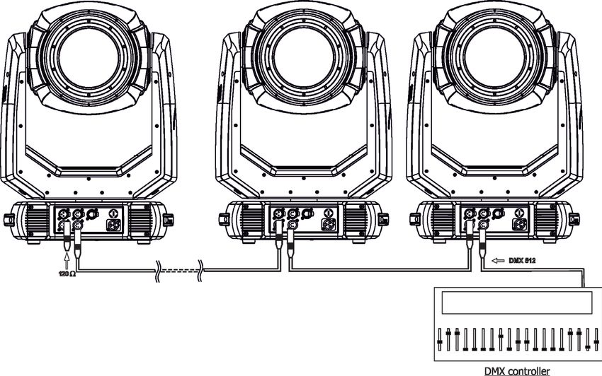
CAUTION!
                          Keep this device away from rain and moisture!
                          Unplug mains lead before opening the housing!

       FOR YOUR OWN SAFETY, PLEASE READ THIS USER MANUAL CAREFULLY
                      BEFORE YOU INITIAL START - UP!

                                         1. Safety instructions
Every person involved with installation and maintenance of this device have to:
- be qualified
- follow the instructions of this manual

                                           CAUTION!
                                Be careful with your operations.
                              With a high voltage you can suffer
                      a dangerous electric shock when touching the wires!

This device has left our premises in absolutely perfect condition. In order to maintain this condition and to en-
sure a safe operation, it is absolutely necessary for the user to follow the safety instructions and warning notes
written in this manual.

The manufacturer will not accept liability for any resulting damages caused by the non-observance of this
manual or any unauthorized modification to the device.

Please consider that damages caused by manual modifications to the device are not subject to warranty.

Never let the power-cord come into contact with other cables! Handle the power cord and all connections with
the mains with particular caution!

Make sure that the available voltage is not higher than stated on the rear panel.

WARNING! This unit does not contain an ON/OFF switch. Always disconnect power input cable
to completely remove power from unit when not in use or before cleaning or servicing the unit.

Make sure that the power cord is never crimped or damaged by sharp edges. Check the device and the pow-
er-cord from time to time.

Always disconnect from the mains, when the device is not in use or before cleaning it. Only handle the pow-
er-cord by the plug. Never pull out the plug by tugging the power cord.

This device falls under protection class I. Therefore it is essential to connect the yellow/green conductor to earth.
The electric connection, repairs and servicing must be carried out by a qualified employee.

Do not connect this device to a dimmer pack.

During the initial start-up some smoke or smell may arise. This is a normal process and does not necessarily
mean that the device is defective.

Do not touch the device’s housing bare hands during its operation (housing becomes hot)!
For replacement use fuses of same type and rating only.

                          LED light emission. Risk of eye injury.
   Do not look straight at the fixture´s LED source during operation. The intense light
                              beam may damage your eyes.

                                                         3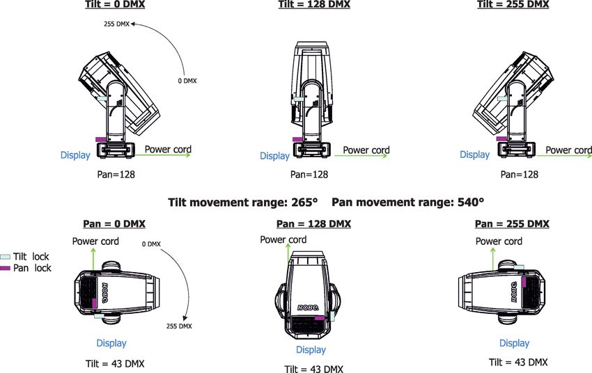
Do not view the light output with optical instruments or any device that may
                                  concentrate the beam.
                           The light source contains blue LEDs.

			CAUTION! Risk group 2, RG-2

                                    2. Operating determination
This device is a moving head for creating decorative effects and was designed for indoor use only.
This device is for professional use only. It is not for household use.

If the device has been exposed to drastic temperature fluctuation (e.g. after transportation), do not switch it on
immediately. The arising condensation water might damage your device. Leave the device switched off until
it has reached room temperature.

Never lift the fixture by holding it at the projector-head, as the mechanics may be damaged. Always hold the
fixture at the transport handles.

When choosing the installation-spot, please make sure that the device is not exposed to extreme heat, moisture
or dust. There should not be any cables lying around. You endanger your own and the safety of others!

Make sure that the area below the installation place is blocked when rigging, derigging or servicing the fixture.

Always fix the fixture with an appropriate safety wire. Fix the safety wire at the correct holes only.

Only operate the fixture after having checked that the housing is firmly closed and all screws are tightly fastened.

The maximum ambient temperature 45°C must never be exceeded.

                                          CAUTION!
             The front lens has to be replaced when it is obviously damaged,
           so that its function is impaired, e. g. due to cracks or deep scratches!

Operate the device only after having familiarized with its functions. Do not permit operation by persons not
qualified for operating the device. Most damages are the result of unprofessional operation!

Do not block the front objective lens with any object when the fixture is under operation.

The fixture housing never must be covered with cloth or other materials.

Please use the original packaging if the device is to be transported.

Please consider that unauthorized modifications on the device are forbidden due to safety reasons!
If this device will be operated in any way different to the one described in this manual, the product may suffer
damages and the guarantee becomes void. Furthermore, any other operation may lead to dangers like short-cir-
cuit, burns, electric shock, burns etc.
                                         CAUTION!
 To avoid damage of the internal parts of the fixture head, never let the sunlight lights
           directly to the front lens , even when the fixture is not working !

Immunity of the equipment is designed for electromagnetic environments E1, E2, E3 according to the standard
EN55103-2 ed.2 Electromagnetic compatibility. Product family standard for audio, video, audiovisual and en-
tertainment lighting control apparatus for professional use. Part 2: Immunity.
The product (covers and cables) must not be exposed to a high frequency electromagnetic field higher than 3V/m.

The installation company should check levels of possible interferences above the tested levels E1,E2,E3 given
by this standard (e.g. transmitters in surrounding area) before installing the equipment.
Emission of the equipment complies with the standard EN55032 Electromagnetic compatibility of multimedia
equipment – Emission Requirements according to class B.
                                                         4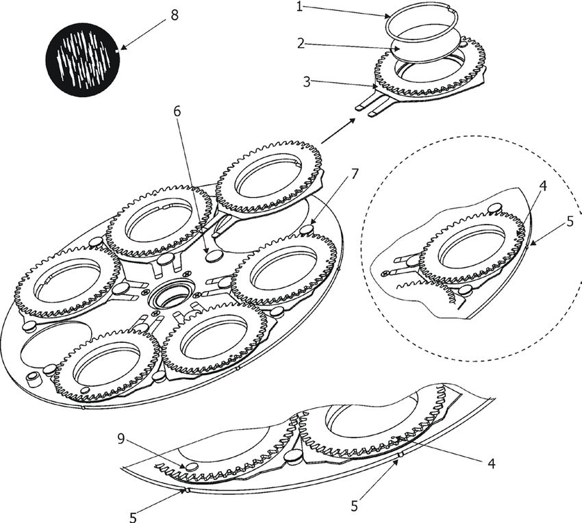
3. Fixture exterior view

                                                                            1 - Front lens
                                                                            2 - Camera*
                                                                            3 - Arm
                                                                            4 - Handle
                                                                            5 - Base
                                                                            6 - Pan lock
                                                                            7 - Tilt lock
                                                                            8 - Head

                                                                            *T1 Profile FS only

The head has to be locked for transportation- the tilt lock latch (7) and the pan lock latch (6) have to be in the
locked positions. To unlock the head, move these latches to unlock positions before operating the fixture.

                                                                               Rear panel of the base:
                                                                               9 - 3-pin DMX output
                                                                               10 - 5-pin DMX output
                                                                               11 - Ethernet input (RJ45)
                                                                               12 - Fuse holder
                                                                               13 - 3-pin DMX input
                                                                               14 - 5-pin DMX input
                                                                               15 - Camera output (RJ 45)*
                                                                               16 - Power (PowerCon True 1)

                                                                                * T1 Profile FS only

                                                                              Front panel of the base:
                                                                              17 - QVGA touch screen
                                                                              18 - ESCAPE button
                                                                              19 - NEXT button
                                                                              20 - ENTER/DISPLAY ON button
                                                                              21 - PREV button
                                                                              22 - USB port

The ENTER/DISPLAY ON button also serves for switching the display on when the fixture is disconnected
from the mains.
                                                        5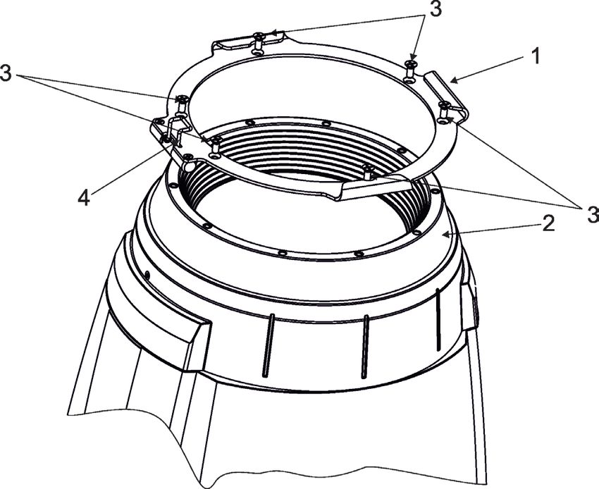
4. Installation

             Fixtures must be installed by a qualified electrician in accordance with all
           national and local electrical and construction codes and regulations.

4.1 Connection to the mains

               For protection from electric shock, the fixture must be earthed!

The Robin T1 Profile is equipped with auto-switching power supply that automatically adjusts to any 50-60Hz
AC power source from 100-240 Volts.
Power cable is enclosed to the fixture.If you need to install a power plug on the power cable to allow connection
to power outlets, install a grounding-type (earthed) plug, following the plug manufacturer’s instructions. If you
have any doubts about proper installation, consult a qualified electrician.

                Core (EU)           Core (US)         Connection      Plug Terminal Marking

                 Brown		              Black           Live                    L

                 Light blue           White           Neutral		               N

                 Yellow/Green         Green           Earth

This device falls under class one and must be earthed (grounded).
To apply power, first check that the head pan and tilt locks are released.

4.2 Replacing the frost

               Unplug the fixture from mains before installing the frost module!

To replace the frost module.
1. Disconnect the fixture from mains and allow it to cool for 10 minutes.
2. Remove plastic cover of the head by loosening the 2 quarter-turn fasteners on the cover to get access to
the frost module (1).

3. The holder (2) of the frost foil is fastened to the frost holder (3) by means of the four magnets (4). Grip the
holder (2) and carefully tilt it out to break a force of magnets (4) on the frost holder (3).

4. Place a new frost module into the frost holder (3). Check, that both slots (6) snapped correctly into two
protrusions (5) in the holder (3).
5. Place the plastic cover back on the fixture before applying power.
                                                        6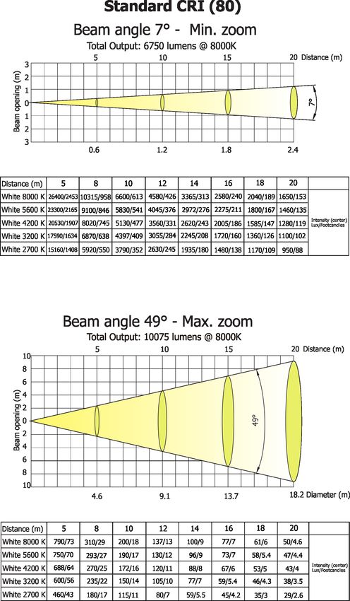
4.3 Replacing gobos

                     Unplug the fixture from mains before replacing gobos!

Rotating gobos
1. Disconnect the fixture from mains and allow it to cool.
2. Remove the plastic cover of the head by loosening the 2 quarter-turn fasteners on the cover.
3. Gently pull up the gobo holder (3) from the rotation gobo wheel.
4. Remove the spring lock (1) with an appropriate tool (e.g. small-bladed screwdriver) and remove it.
   Do not touch the surface of the pattern of the glass gobo with bare fingers.
5. Remove the original gobo (2) and insert the new one (glossy side towards the light source).
   The Robe gobo has a small position point (8) at its edge which has to aim at the position point (4) on
   the gobo holder (4). Insert the spring lock to secure correct gobo position in the gobo holder.
6. Insert he gobo holder back under the distance slots (6, 7) into rotating gobo wheel in this way, that its
  position point (4) has to aim at a small toothlike projection (5) on the edge of the rotating gobo wheel.
Important! When inserting the gobo holder back to the rotating gobo wheel, one of the adjacent gobo holder
has to be oriented according to the same rule, it means that its position point (4) has to aimed at the toothlike
projection (5) on the edge of the rotating gobo wheel. You have keep both marks (4) and (5) side by side when
rotating the gobo wheel to the position allows inserting the gobo holder back.
5. Replace the plastic cover before applying power.
6. Use the menu Service to fine adjust replaced gobo (Service -> Calibration -> Calibrate effects -> R. Gobo
Index 1 ...R. Gobo Index 7).
Note. The magnet (9) of the gobo holder has the same function as the position point (4) on the rest of gobo
holders.

                                                       7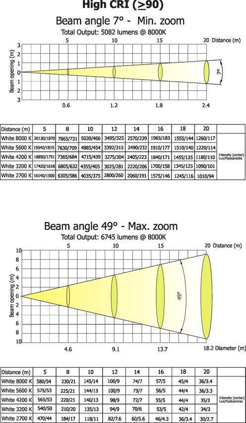
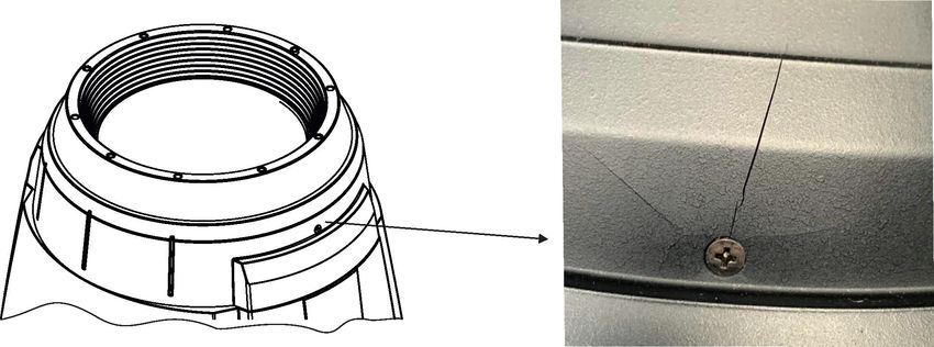
4.4 Installing the top hat

               Disconnect the fixture from mains before installing the top hat.

1. Disconnect the fixture from mains.
2. Remove the original gel frame adaptor P/N 10980440 (1) from the fixture head (2) by unscrewing six screws
   M4x10 (3)
3. Screw the new gel frame adaptor P/N 10980474 (supplied with the top hat) by means of the six screws
   M4x10 (3).
4. Insert the top hat to the gel frame adaptor and secure it by a spring lock (4).

Note: the gel frame adaptor P/N 10980474 serves for the top hat only.
If you need to insert the gel frame (P/N 10980443) to the frame adaptor, you should screw the original gel frame
adaptor P/N 10980440.

                                                       8
4.5 Rigging the fixture
A structure intended for installation of the fixture(s) must safely hold weight of the fixture(s) placed on it. The
structure has to be certificated to the purpose.
The fixture (fixtures) must be installed in accordance with national and local electrical and construction codes
and regulations.
For overhead installation, the fixture must be always secured with a safety wire
that can bear at least 10 times the weight of the fixture
When rigging, derigging or servicing the fixture staying in the area below the installation place, on bridges,
under high working places and other endangered areas is forbidden.
The operator has to make sure that safety relating and machine technical installations are approved by an ex-
pert before taking into operation for the first time and after changes before taking into operation another time.
The operator has to make sure that safety relating and machine technical installations are approved by a skilled
person once a year.
Allow the fixture to cool for ten minutes before handling.
The projector should be installed outside areas where persons may walk by or be seated.
IMPORTANT! OVERHEAD RIGGING REQUIRES EXTENSIVE EXPERIENCE, including calculating working
load limits, installation material being used, and periodic safety inspection of all installation material and the
projector. If you lack these qualifications, do not attempt the installation yourself, but use a help of professional
companies.
CAUTION: Fixtures may cause severe injuries when crashing down! If you have doubts concerning the safety
of a possible installation, do not install the fixture!
The fixture has to be installed out of the reach of public.
The fixture must never be fixed swinging freely in the room.
. Danger of fire !
When installing the device, make sure there is no highly inflammable
material (decoration articles, etc.) in a distance of min. 0.5 m.
CAUTION!
Use 2 appropriate clamps to rig the fixture on the truss.
Follow the instructions mentioned at the bottom of the base.
Make sure that the device is fixed properly! Ensure that the
structure (truss) to which you are attaching the fixtures is secure.
The fixture can be placed directly on the stage floor or rigged in any orientation on a truss without altering its
operation characteristics .
For securing the fixture to the truss, install a safety wire which can hold at least 10 times the weight of the fixture.
Use only the safety wire with a snap hook with screw lock gate.
9
Truss installation
1.Bolt clamps (4) to the brackets Omega CL (1) with M12 bolts and lock nuts through the hole in the bracket
  Omega CL.
2.Fasten the brackets Omega CL on the bottom of the base by means of the quick-lock fasteners (2) and tighten
  them fully clockwise.
3. Pull a safety wire (3) through the carrying handle and the truss (6) as hown on the picture below in a suitable
  position so that the maximum fall of the fixture will be 20 cm. Fasten a snap hook in the attachment point (5).
  Use only the safety wire with a snap hooks with screw lock gates.

                                                                             1-Mounting bracket Omega CL
                                                                             2-Quick-lock fasteners
                                                                             3-Safety wire
                                                                             4-Clamps
                                                                             5-Attachment point
                                                                             6-Truss

                              When installing fixtures side-by-side,
                            avoid illuminating one fixture with another!

                                   DANGER TO LIFE!
  Before taking into operation for the first time,the installation has to be approved by
                                        an expert!

                                                       10
4.6 DMX-512 connection
The fixture is equipped with both 3-pin and 5-pin XLR sockets for DMX input and output.The sockets are wired
in parallel.
Only use a shielded twisted-pair cable designed for RS-485 and 3-pin or 5-pin XLR-plugs and connectors in
order to connect the controller with the fixture or one fixture with another.
DMX output DMX input
XLR mounting sockets (rear view): XLR mounting plugs (rear view):
1 - Shield 1 - Shield
2 - Signal (-) 2 - Signal (-)
3 - Signal (+) 3 - Signal (+)
4 - Not connected 4 - Not connected
5 - Not connected 5 - Not connected
If you are using the standard DMX controllers, you can connect the DMX output of the controller directly with
the DMX input of the first fixture in the DMX chain. If you wish to connect DMX controllers with other XLR out-
puts, you need to use adapter cables.
Building a serial DMX-chain:
Connect the DMX-output of the first fixture in the DMX chain with the DMX-input of the next fixture. Always connect
one output with the input of the next fixture until all fixtures are connected. Up to 32 fixtures can be conected.
Caution: At the last fixture, the DMX-cable has to be terminated with a terminator. Solder a 120 Ω resistor
between Signal (–) and Signal (+) into a 3-pin XLR-plug and plug it in the DMX output of the last fixture.
114.7 Ethernet connection
The fixtures on a data link are connected to the Ethernet with ArtNet communication protocol.The control soft-
ware running on your PC (or light console) has to support Art-Net protocol.
Art-Net communication protocol is a 10 Base T Ethernet protocol based on the TCP/IP.Its purpose is to allow
transfer of large amounts of DMX 512 data over a wide area using standard network technology.
IP address is the Internet protocol address.The IP uniquely identifies any node (fixture) on a network.
The Universe is a single DMX 512 frame of 512 channels.
The Robin T1 Profile is equipped with 8-pin RJ- 45 socket for Ethernet input.Use a network cable category 5
(with four “twisted” wire pairs) and standard RJ-45 plugs in order to connect the fixture to the network.
RJ-45 socket (front view): RJ-45 plug (front view):
1- TD+ 5- Not connected
2- TD- 6- RX-
3- RX+ 7- Not connected
4- Not connected 8- Not connected
Patch cables that connect fixtures to the hubs or LAN sockets are wired 1:1,that is,pins with the same numbers
are connected together:
1-1 2-2 3-3 4-4 5-5 6-6 7-7 8-8
If only the fixture and the computer are to be interconnected,no hubs or other active components are needed.A
cross-cable has to be used:
1-3 2-6 3-1 4-8 5-7 6-2 7-5 8-4
If the fixture is connected with active Ethernet socket (e.g. switch) the network icon will appear at the
bottom right corner of the screen:
Direct Ethernet operation
Connect the Ethernet inputs of all fixtures with the Ethernet network.
Option “ Artnet" (gMaI or gMA2 or sACN) has to be selected from “Ethernet Mode” menu at each fixture.
Set IP address (002.xxx.xxx.xxx / 010.xxx.xxx.xxx) and the Universe at each fixture.
(DMX address=144) (DMX address=48) (DMX address=1)
IP addres=002.168.002.004 IP addres=002.168.002.003 IP addres=002.168.002.002
Universe=1 Universe=1 Universe=1
An advised PC setting: IP address: 002.xxx.xxx.xxx / 010.xxx.xxx.xxx (Different from fixture IP addresses)
NET mask: 255.0.0.0
12Ethernet / DMX operation
Option “ Artnet" (gMaI or gMA2 or sACN) has to be selected from “Ethernet Mode” menu at first fixture.
Option “Ethernet To DMX” has to be selected from the “Ethernet Mode” menu at the first fixture (connected to
the Ethernet) in the fixture chain, next fixtures have standard DMX setting.
Connect the Ethernet input of the first fixture in the data chain with the network. Connect the DMX output of this
fixture with the input of the next fixture until all fixtures are connected to the DMX chain.
Caution: At the last fixture, the DMX chain has to be terminated with a terminator. Solder a 120 Ω resistor
between Signal (–) and Signal (+) into a XLR-plug and connect it in the DMX-output of the last fixture.
Example:
DMX address=1 DMX address=48 DMX address=144
IP addres=002.168.002.002
Universe=0
DMX address=1 DMX address=48 DMX address=144
IP addres=002.168.002.003
Universe=1
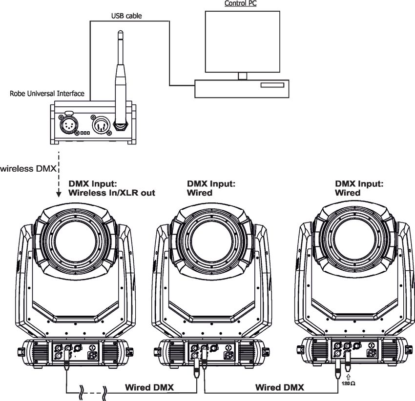
134.8 Wireless DMX operation
The wireless version of the Robin T1 Profile is equipped with the Lumen Radio CRMX module and antenna
for receiving DMX signal. CRMX module operates on the 2.4 GHz band.
The item " Wireless " from the menu "DMX Input" allows you to activate receiving of wireless DMX (Person-
ality--> DMX Input -->Wireless.). First two options from the "DMX Input" menu are stated in DMX chart as well
(channel Power/Special functions , range of 10-19 DMX). If DMX input option is changed by DMX command,
the change is permanently written into fixture´s memory.
DMX range of 10-19 switching fixture to the wired/wireless operation is active only during first 10 sec-
onds after switching the fixture on.
After switching the fixture on, the fixture checks both modes of receiving DMX in the following order:
1. For the first five seconds, the fixture receives DMX signal from the wired input. If the Power/Special functions
channel is set at some DMX input option, the fixture will receive DMX value according to this option. If DMX input
option is set to the wired input , this option is saved and checking procedure is finished. If DMX input option is
not set, the fixture continues next 5 seconds in scanning wireless DMX signal-see point 2.
2. For the next 5 seconds the fixture receives wireless DMX signal and again detects if the Power/Special
functions channel is set at some DMX input option, if not, the fixture will take option which is set in the fixture
menu "DMX Input".
To link the fixture with DMX transmitter.
The fixture can be only linked with the transmitter by running the link procedure at DMX transmitter .
After linking , the level of DMX signal ( 0-100 %) is displayed in the menu item “Wireless State“ (Information
-->Wireless State).
To unlink the fixture from DMX transmitter.
The fixture can be unlinked from receiver via the menu item “ Unlink Wireless Adapter“ (Information--> Wireless
State --> Unlink Wireless Adapter).
Example of connection:
145. Remotely controllable functions
5.1 Colour influencing functions
Factory setting of menu functions (channels) which influence behaviour of colour channels is the following:
Function Factory setting Function Factory setting
DMX mode 1 Uniformity Off
Colour calibration mode On Colour mix control 0 DMX
Colour mixing mode CMY CTC 110 DMX (5600K)
Dimmer curve Square law CRI Selection Standard (80)
Tungsten effect simulation Off Green correction Uncorrected
Chromatic white Off Shutter/Strobe Open (32 DMX)
Light output stability Off Dimmer Closed (0 DMX)
Colour calibration mode (menu tab "Personality")
The function switches on/off an internal control of colours. For a standard operation of the fixture the option
should be switched on. Option off has to be set during colour calibration of the fixture (in this mode some
functions e.g. Tungsten effect, Virtual colour wheel are disabled).
Colour mixing system (menu tab "Personality", DMX channel "Colour functions")
This item allows selection between RGB and CMY mode. In both 3-colour controlling modes (Mode 1,Mode 2)
all internal 5 colours are always utilized where possible.
Dimmer curve (menu tab "Personality", DMX channel "Colour functions")
The fixture allows you to select a linear dimmer curve or a square law curve.
Tungsten effect simulation (menu tab "Personality", DMX channel "Colour functions")
The function simulates behaviour of a halogen lamp during dimming at calibrated white colours 2700K - 4200K.
You can select from various lamp wattage simulation: 750W, 1000W, 1200W, 2000W, 2500W.
If the function Chromatic white is on, the Tungsten effect will influence also mixed colours.
Saving user colours (DMX channel "Colour functions")
To save user colours:
1.Set the function White Point to off (Channel Colour Mix Control, range 70-79 DMX).
1.Mix desired colour on colour channels.
2.Stay in desired position of user colours (216-235 DMX) on the Virtual colour wheel for 1 sec.
3.Leave the range of user colours (216-235 DMX) on the Virtual colour wheel.
4. Repeat steps 2-4 for next user colour.
5.To permanently save user colours, stay for 3 sec. at DMX range of 110-114 on the channel Colour functions.
After that the colour system will be reset (this action can last about 2 minutes). Previous user colours will be
overwritten.
Chromatic white (menu tab "Personality", DMX channel "Colour functions")
If the function is on, the CTC channel influences calibrated white colours and mixed colours (also colours on
Virtual colour wheel).
If the function is off, the CTC channel influences calibrated whites only.
Light output stability (menu tab "Personality", DMX channel "Colour functions")
If the function is on, the light output from the fixture is immediately reduced to a value corresponding to a thermal
drop of the light intensity from the LED engine (the thermal drop of light intensity - decreasing of the light intensity
on circa 90 % of starting level after first 5 minutes, then is the thermal drop of light intensity inconsiderable).
Output Uniformity (menu tab "Personality", DMX channel "Colour functions")
If the function is on, the light intensity from the fixture is corrected in order to get approximately the same light
intensity as from another fixture which has also the function on. Light outputs from more fixtures will have
approximately the same light intensity. Thanks to the function, light outputs from more fixtures will have ap-
proximately the same light intensity.
15Colour Mix control (DMX channel "Colour Mix control")
The Colour Mix control channel defines relation between colour channels (Cyan, Magenta, Yellow, Red, Green,
Blue, Amber, Light Green and CTC ) and the colours on the virtual colour wheel:
DMX value Function
0 - 9 Virtual colour wheel has priority over colour channels (default setting)
10-19 Maximum mode (highest values have priority)
20-29 Minimum mode (lowest values have priority)
30-39 Multiply mode (multiply virtual colour wheel and colour channels)
40-49 Addition mode (virtual colour wheel + colour channels)
50-59 Subtraction mode (virtual colour wheel – colour channels)
60-69 Inverted Subtraction mode (virtual colour wheel – colour channels)
70-79 White Point Off (CTC+green correction+virtual col. wheel deactivated)
80-128 Reserved
129 Crossfade Virtual colour wheel only
130-254 Crossfade between virtual colour wheel and colour channels
255 Crossfade colour channels only
CTC (DMX channel " Colour temperature correction")
The CTC channel allows you to change a colour temperature of calibrated white colours in range of 8000K-2700K
and also can influence mixed colours including colours on the Virtual colour wheel.
For correct function of the CTC channel on calibrated white colours, the following conditions have to be kept:
1.The Colour calibration mode has to be set on.
If the Chromatic white is set off, the CTC channel influences white colours only.
If the Chromatic white is set on, the CTC channel influences white colours and mixed colours including
colours on the Virtual colour wheel.
2. The following channels have to be set at:
Virtual colour wheel at 0 DMX
Green correction at 128 DMX
Colour mix control channel at 0 DMX
3. Colour channels have to be set depending on the colour mixing mode and the DMX mode.
CMY colour mixing mode.
DMX mode 1:
Channels Cyan/Red, Magenta/Green and Yellow/Blue (both 8-bit and 16-bit channels for each colour) have to
be set at 0 DMX or at the same DMX value (except 255 DMX).
DMX mode 2:
Channels Cyan/Red, Magenta/Green and Yellow/Blue have to be set at 0 DMX or at the same DMX value
(except 255 DMX) .
DMX mode 3:
The mode is not intended for CMY colour mixing mode.
RGB(A,LG) colour mixing mode
DMX mode 1:
Channels Cyan/Red, Magenta/Green and Yellow/Blue (both 8-bit and 16-bit channels for each colour) have to
be set at 255 DMX or at the same DMX value (except 0 DMX).
DMX mode 2:
Channels Cyan/Red, Magenta/Green and Yellow/Blue have to be set at 255 DMX or at the same DMX value
(except 0 DMX).
DMX mode 3:
Channels Red, Green, Blue, Amber, Light Green (both 8-bit and 16-bit channels for each colour) have to be set
at 255 DMX or at the same DMX value (except 0 DMX).
4. Shutter and dimmer have to be open.
CRI correction (DMX channel " CRI Selection")
The channel allows you to set CRI from Standard (80) to High (90+). Default setting is to 0 DMX (Standard CRI).
16Green correction (DMX channel "Green correction ")
The channel allows you a fine correction of colours (whites, mixed colours, colours on the Virtual colour wheel).
E.g. white colour from red to green tint.
Virtual colour wheel (DMX channel " Virtual colour wheel")
The virtual colour contains 67 preset colours,10 user colours and 70 multicolours. The multicolours are intended
to use with the following effects only:
Effect wheel (DMX range: 20-255)
Effect wheel animation (DMX range: 8-27)
Rotating gobo wheel (DMX range: 4-199; 202-255)
Prism (DMX range: 20-255)
At least one othe effects stated above has to be inserted into the light beam.
There is several examples of using multicolours with prism/gobo combination:
Dimmer/Shutter (DMX channels " Shutter/Strobe" and "Dimmer Intensity")
Smooth 0 - 100 % dimming is provided by the electronic control unit of the light source. The control of the light
source also allows strobe effects with variable speed.
175.2 Effect functions
Effect wheel
The wheel rotates in both directions with variable speed which creates wide spectrum of graphic effects.
Gobo wheel
The fixture includes rotating gobo wheel with 7 glass gobos rotating in both directions, indexable, replaceable
"SLOT&LOCK” system.
Prism
The 6-facet prism rotates in both directions at different speeds, 16 prism/gobo macros are available.
Frost
Two frost filters (light 0.5°and medium 10°) provide variable frost for fine frosting. The medium frost is replaceable.
Iris
Motorized adjustable iris, wide range of variable pulse effects.
Zoom
Motorized zoom unit enables zoom between 7 °- 49°.
Focus
Motorized focus allows to focus beam from approx. 2 meters to infinity.
Framing system
Framing system consists of four framing shutters. There is individual control of each shutter blade position
and angle, together with rotation of the complete framing module. As well as providing a sharp precise or soft
frame for the projected image.
Framing system orientation:
18Pan/Tilt
Fast pan/tilt movement due to built-in electronic motion stabilizer (EMS). The electronic motion stabilizer ensures
precise position of the fixture´s head during its movement and reduces its swinging when the truss shakes.
Pan /Tilt movement range: 0-540°/0-265°.
196. Control menu map
Default settings=Bold print
Tab Level 1 Level 2 Level 3 Level 4 Level 5 Level 6
Addressing Settings DMX Address 001-512
DMX Presets Mode 1
Mode 2
Mode 3
View Selected Preset
Ethernet Settings Ethernet Mode Disable
ArtNet
gMAI
gMA2
sACN
Ethernet To DMX Off, On
IP Address/Net Mask Default IP Address
Custom IP Address
Net Mask
ArtNet Universe 0-255
MANet settings MANetI/II Universe 01-256
MANet Session ID 01-32
sACN Settings sACN Universe 00001-32000
Information Fixture Times Power On Time Total Hours
Resetable Hours
LEDs On Time Total Hours
Resetable Hours
Air Filters Elapsed Time
Alert Period 10-300
Fixture Temperatures LEDs Temperatures Cur. RA, GY, B
Max. RA, GY, B
Max.Res. RA, GY, B
LEDs Brd. 1 Temperature Current
Maximum NonRes.
Maximum Res.
LEDs Brd. 2 Temperature Current
Maximum NonRes.
Maximum Res.
Base Temperature Current
Maximum NonRes.
Maximum Res.
DMX Values Pan
:
Dimmer Fine
Wireless State Signal Quality
Unlink
Wireless Adapter
Power Channel state
Colour functions state
Software Versions Display System
Module M
Module L-A
Module L-B
Module L-C
Module O
20Tab Level 1 Level 2 Level 3 Level 4 Level 5 Level 6
Module F-A
Module F-B
Module G
Module FR
Product IDs Mac Address
RDM UID
RDM Label
View Logs Fixture Errors
Fixture States Power On
Power Off
Fixture Position
Fixture Temperatures LEDs B.1 Temperature
LEDs B.2 Temperature
Base Temperatures
Personality User Mode User A Settings
User B Settings
DMX Presets Mode 1
Mode 2
Mode 3
View Selected Preset
DMX Input Wired
Wireless
Wireless In/XLR Out
Pan/Tilt Settings Pan Reverse Off, On
Tilt Reverse Off, On
Pan/Tilt Feedback Off, On
Pan/Tilt mode Time
Speed
Pan/Tilt EMS Off
Soft
Medium
Hard
Microphone Sen- 1-10-20
sitivity
Blackout Settings Blackout During M.C. Off, On
Blackout while: Pan/Tilt moving Off, On
Gobo Wheel Moving Off, On
Quiet Mode Off
Quiet 0-100%
Colour Calibration On, Off
Mode
Colour Mixing Mode CMY, RGB
Chromatic White Off, On
Light Output Stability On, Off
Output Uniformity On, Off
Frequency Setup 300 Hz
600Hz
1200Hz
2400Hz
Frequency Adjust
User Colours View User Colours View User Colour 1..
View User Colour 10
Distribute User Colours
Thungsten Eff. Sim. Off
750W
1000W
1200W
21Tab Level 1 Level 2 Level 3 Level 4 Level 5 Level 6
2000W
25000W
Init Effect Positions Pan 0-255
:
Dimmer Fine 0-255
Screen Settings Display Intensity 1-10
Screen Saver Delay Off-10min.
Touchscreen Lock Off-10min.
Recalibrate Touchscreen
Display Orientation Normal
Inverted
Auto
Temperature Unit °C,°F
Fan Mode Auto
High
Dimmer Curve Linear
Square law
Date & Time Settings
Default Settings
Password Protection Off, On
Reset Web Password
Manual Control Reset Functions Total System Reset
Pan/Tilt reset
Gobo/Eff. Wh. Reset
Optics/Prism/Frost Res.
Iris/framing Sh. Reset
Manual Effect Control Pan 0-255
:
Dimmer Fine 0-255
Stand -Alone Test Sequences Dynamic Mode
Static Mode Pan 0-255
Tilt 0-255
Zoom 0-255
Focus 0-255
MusicTrigger Off, On
Preset Playback None
Test
Prog. 1
Prog. 2
Prog. 3
Play Program Play Program 1
Play Program 2
Play Program 3
Edit Program Edit Program 1 Start Step 1-80
Edit Program 2 End Step 1-80
Edit Program 3 Edit Program Steps Step 1 Pan 0-255
: :
: Dimmer Fine 0-255
: Step Time 0-25,5 sec.
Step 100 Pan 0-255
:
Dimmer Fine 0-255
Step Time 0-25,5 sec.
22Tab Level 1 Level 2 Level 3 Level 4 Level 5 Level 6
Service Adjust DMX Values Pan 0-255
:
Dimmer Fine 0-255
Calibrations Calibrate Effects Pan 0-255
Tilt 0-255
Effect Wheel 0-255
Rot. Gobo Wheel 0-255
R. Gobo Index 1 0-255
:
R. Gobo Index 7 0-255
Prism 1 0-255
Prism 2 0-255
Zoom 0-255
Focus 0-255
Iris 0-255
Frost 1/1 0-255
Frost 1/2 0-255
Frost 2/1 0-255
Frost 2/2 0-255
Fr. Shutters rot. 0-255
Fr. Shutter 1 Move 0-255
Fr. Shutter 1 Swiv 0-255
Fr. Shutter 2 Move 0-255
Fr. Shutter 2 Swiv 0-255
Fr. Shutter 3 Move 0-255
Fr. Shutter 3 Swiv 0-255
Fr. Shutter 4 Move 0-255
Fr. Shutter 4 Swiv 0-255
Calibrate Fr. Hysteresis Framing Lamella 1 0-8
Framing Lamella 2 0-8
Framing Lamella 3 0-8
Framing Lamella 4 0-8
Calibrate colours Red Calibration 0-255
Green Calibration 0-255
Blue Calibration 0-255
Amber Calibration 0-255
Light GreenCalibration 0-255
Green Corrections 110-145
Opto Corrections
Calibrate Pan/Tilt EMS
Load Default Calibrations
LEDs HW Version
Update Software
237. Control menu
The Robin T1 Profile is equipped with the QVGA Robe touch screen with battery backup which
allows you to set the fixture´s behaviour according to your needs, obtain information on its operation, control
all range of effects and program it in stand-alone mode.
The fixture´s menu can be controlled either by the control buttons or directly by touching the icon.
Control buttons on the front panel:
[ESCAPE] button used to leave the menu without saving changes.
[NEXT] , [PREV] buttons for moving between menu items and symbols, adjusting values.
[ENTER/Display On] button used to enter the selected menu (menu item) and to confirm adjusted value.
If the fixture is disconnected from mains, the button switches the touch screen on.
Icons used in the touch screen menu:
- [back arrow] used to move back to the previous screen (menu).
- [up arrow] used to move up on the previous page.
- [down arrow] used to move down on the next page.
- [confirm] used to save adjusted values, to leave menu or to perform desired action.
- [cancel] used to leave menu item without saving changes.
- [confirm+copy] used to save adjusted values and copy them to the next prog. step.
- [warning icon] used to indicate some error which has occurred in the fixture.
- [Ethernet] used to indicate Ethernet connected.
- [menu rotation] used to rotate menu 180 degrees from current orientation.
- [slider control] used to recall slider system for setting desired value.
- [keyboard control] used to recall keyboard system for setting desired value.
- [air filters cleaning] used to signal that cleaning period of the air filters elapsed.
The menu page displays icons for each function that you can perform from the touch screen.
After switching the fixture on, the touch screen shows the screen with the ROBE logo:
24Touch any part of the screen or press the [ENTER/Display On] button to display the initial screen with the cur-
rent stored DMX address:
Note: The green icon at the top right corner of the screen indicates the level of the display battery charging. If
the whole icon is green, the battery is fully charged while the red icon indicates exhausted battery. The battery
charges during fixture operation, its charging lasts cca 6 hours.
We recommend that the fixture should be in operation at least 7 hours per week to keep the battery fully charged.
If you switch the fixture on and this screen will not appear till 1 minute, switch the fixture off and on again. If the
screen lights, the battery is exhausted. In case the screen still does not light, the battery is faulty.
This is also indicated by an error message "Faulty battery" and if such an error message appears the battery
should be replaced immediately. The lifetime of the battery is highly dependent on ambient temperature (and
consequently on base temperature). If the maximum ambient temperatures (as recorded and displayed in menu:
Information -> Fixture Temperatures -> Ambient Temperature -> Maximum NonRes.) are kept within the spec-
ified limits, the battery should last for at least two years. Shell the ambient temperatures exceed the specified
maximum temperature, the lifetime of the batteries could be considerably shortened even up to just one year
or less and also result in physical damage (battery leakage) or unreliable fixture functions.
Damage caused by batteries failed due to exceeded maximum ambient temperature cannot be claimed under
warranty terms.
Touch the green arrow at the bottom right corner of the screen or press the [ENTER/Display On] button to enter
the " Address" menu.
Each item (such as a Tab, menu item, text box, icon) may be selected from a screen by simply touching the
item in the list or by pressing the [NEXT] or [PREV] buttons to scroll through list items. With each press, the
next item is highlighted. Press [ENTER/Display On] to select the highlighted item.
Before first fixture operation, set current date and time in the menu "Date &Time
Setings" (menu path: Personality--> Date &Time Setings).
7.1 Tab " Address"
DMX Address - Select the menu to set the DMX start address.
DMX Preset - Use the menu to select desired channel mode.
DMX Preset - Use the menu to select desired channel mode.
Mode 1 - 49 control channels
Mode 2 - 33 control channels
Mode 3 - 53 control channels
View Selected Preset - Use the menu to display channels included in the selected mode.
Ethernet Settings - The menu allows all needed settings for the Ethernet operation
Ethernet Mode
Disable - The option disables Ethernet operation.
Artnet - Fixture receives Artnet protocol
gMAI - Fixture receives MANet I protocol
gMA2 - Fixture receives MANet 2 protocol
25sACN - Fixture receives sACN protocol
Ethernet To DMX - Fixture receives protocol from the Ethernet input and sends DMX
data to its DMX output (fixture works as an "Ethernet/DMX converter", next fixture can
be connected to its DMX output and you can build a standard DMX chain by connecting another fixtures.
Only one fixture has to be connected to the Ethernet.
IP Address/Net Mask - Select this menu to set IP address. IP address is the Internet protocol
address.The IP uniquely identifies any node (fixture) on a network.
There cannot be 2 fixtures with the same IP address on the network!
Default IP Address -Preset IP address, you can set up only first byte of IP address
(2 or 10) e.g. 002.019.052.086.
Custom IP Address - The option enables to set up all bytes of IP address.
Net Mask - The option enables to set up all bytes of Net Mask.
ArtNet Universe - Use this item to set a Universe (0-255). The Universe is a single DMX
512 frame of 512 channels.
MANet Settings - Use this menu to set parameters for MANet operation.
MANet Universe I/II - The value of this item can be set in range 1-256.
MANet Session ID - The value of this item can be set in range 1-32.
sACN Settings - Use this menu to set parameters for sACN operation.
sACN Universe - The value of this item can be set in range 1-32000.
7.2 Tab "Information"
Fixture Times - The menu provides readouts of fixture and LED module operation hours.
Power On Time Hours - Select this menu to read the number of fixture operation hours.
Total Hours - The item shows the total number of the operation hours since the
Robin T1 Profile has been fabricated.
Resetable Hours - The item shows the number of the operation hours that the
Robin T1 Profile has been powered on since the counter was last reset.
In order to reset this counter to 0, touch the text box next to the item "Resetable Hours:"
LEDs On Time - Select this menu to read the number of LEDs operation hours.
In order to reset some counter to 0, touch the yellow text box next to desired colour.
Air Filters - Regular cleaning of the air filters is very important for the fixture´s life and performance.
Bild-up of dust, dirt and fog fluid residues reduces the fixture´s light output and cooling ability.
The two items of this menu help you to keep cleaning period of the air filters.
Alert period - Cleaning schedule for the fixture depends on the operating environment.
It is therefore impossible to specify accurate cleaning interval. This item allows
you to change the cleaning interval of the air filters. This "alert" value is 300 hours and it
is set as default. Inspect the fixture within its 300 hours of operation to see whether cleaning
is necessary. If cleaning is required, clean all air filters and change the value in this menu
on acceptable level. Min. level of alert period is 10 hours, max. is 300 hours.
Elapsed Time - The item allows you to read the time which remains to cleaning air filters.
The time period is set in the menu mentioned above.
Expired time period is signalled by a negative mark (-) at the time value and a warning icon
on the display.
Clean the filters and reset this menu item (by touching the text box next to the item
"Elapsed Time").
Fixture Temperatures - The menu is used to view temperatures of the fixture´s inside.
LEDs temperatures - The menu shows temperature on the LED PCBs in the light source (RA=red + amber
LEDs, GY=green + light green LEDs, B=blue LEDs).
Cur. - A current temperature of the LED PCBs.
Max. - A maximum temperature of the LED PCBs since the fixture has been fabricated.
26Max. Res. - A maximum temperature of the LED PCBs since the counter
was last reset.
In order to reset some counter to 0, touch desired text box under item "Max.Res."
LEDs Brd.1 Temperature - The menu shows temperature on the LEDs control PCB (RB 3401-top side with
coils) in the fixture head.
Current - A current temperature on the LEDs control PCB.
Maximum NonRes. - A maximum temperature on the LEDs control PCB since
the fixture has been fabricated.
Maximum Res. - A maximum temperature on the LEDs control PCB since the counter
was last reset.
In order to reset this counter to 0, touch the text box next to the item "Maximum Res."
LEDs Brd.2 Temperature - The menu shows temperature on the LEDs control PCB (RB 3401-bottom side)
in the fixture head.
Current - A current temperature on the LEDs control PCB.
Maximum NonRes. - A maximum temperature on the LEDs control PCB since
the fixture has been fabricated.
Maximum Res. - A maximum temperature on the LEDs control PCB since the counter
was last reset.
In order to reset this counter to 0, touch the text box next to the item "Maximum Res."
Base Temperature - The menu shows temperature on the display PCB in the fixture base.
Current - A current temperature on the display PCB.
Maximum NonRes. - A maximum temperature on the display PCB since the fixture has
been fabricated.
Maximum Res. - A maximum temperature on the display PCB since the counter
was last reset.
In order to reset this counter to 0, touch the text box next to the item "Maximum Res."
DMX Values - The menu items allows you to read DMX values of each channel received by the fixture.
Wireless State - The menu serves for reading of the wireless operation status.
Unlink Wireless Adapter - The item serves for unlinking the fixture from a DMX transmitter.
If the wireless module is not installed in the fixture, message" Wireless Module Not Installed" will appear.
Power Channel State - Select this item to see current setting of the functions, which can be set by menu items
in "Personality" as well as by DMX command at channel "Power/Special functions".
Colour Functions State - Select this item to see current setting of the colour functions, which can be set by
menu items in "Personality" as well as by DMX command at channel "Colour functions".
Software Version - Select this item to read the software version of the fixture processors:
Display System - A display processor on the display board in the fixture base
Module M - Pan/Tilt processor
Module L-A - LEDs control processor
Module L-B - LEDs control processor
Module L-C - LEDs control processor
Module O - Focus/Zoom/Prism/ control processor
Module F-A -Framming shutters control processor
Module F-B - Framming shutters + Iris control processor
Module G - Rot. gobo/Effect wheel control processor
Module P - Prism rotation/Frost control processor
Product IDs - The menu is used to read the MAC Address ,RDM UID and RDM Label.
View Logs - Use this menu to read fixture´s data which have been recorded during fixture operation. This
colected data allows easier troubleshooting.
Fixture Errors - Use this menu to read fixture errors which have occured during fixture operation.
Fixture States - In the menu are recorded fixture states as power on and power off.
27Fixture Positions - In the menu are recorded installation positions of the fixture:
Display
Display
Front Normal Front Inverted Side Top Side Bottom Top Bottom
Fixture Temperatures - In the menu are recorded temperatures which have exceeded defined levels.
Note: The log buffer can contain max. 8000 records. If the buffer is full, old data will be overwritten.
7.3 Tab "Personality"
User mode - The Robin T1 Profile allows you to recall two user settings. After switching the fixture on for the
first time, the User A settings is active. Now all changes made in the “Personality” menu , ”Addressing” menu
and the “Music Trigger“ and “ Preset Playback“ items from the “Stand-alone” menu are saved to the User A
settings. If you now select the User B settings, from this moment the changes made in these menus will be
saved to the User B settings. After switching the fixture off and on, the User B setting is active. In this way you
may use the two fixture operating behaviours.
User A Settings - the function recalls the user A settings.
User B Settings - the function recalls the user B settings.
DMX Preset - Use the menu to select desired channel mode.
Mode 1 - 49 control channels
Mode 2 - 33 control channels
Mode 3 - 53 control channels
View Selected Preset - Use the menu to display channels included in the selected mode.
DMX Input- Use the menu to select mode of DMX signal receiving.
Wired - DMX signal is received by means of the standard DMX cable.
Wireless - DMX signal is received by means of the inbuilt wireless module.
Wireless In/XLR Out- the fixture receives wireless DMX and sends the signal to its wired DMX output.
The fixture behaves as " Wireless/Wired" adapter.
The options "Wired" and "Wireless" are also stated in DMX chart (channel Power/Special functions).
Note. If the wireless module is not installed in the fixture, the following message will appear:
DMX Input Set to Wired
Wireless Module Missing
If the fixture is not connected to mains, the message "Not Available In Off line Mode" will appear after entering
the menu DMX Input. To enter this menu, the fixture has to be connected to mains.
Pan/Tilt Settings - Use the menu set behaviour of both pan and tilt movements.
Pan Reverse - The item allows to invert pan movement.
Tilt Reverse - The item allows to invert tilt movement.
Pan/Tilt Feedback - The item allows to return the mowing head to the required pan/tilt position after
changing the position by an external force if this option is set on.
Note. Be careful, the Pan/Tilt Feedback should be permanent On, the option Off is not suitable for standard
operation and the head of the fixture can be damaged!
Pan/Tilt mode - Use this menu to set the mode of the pan/tilt movement
Time mode – The pan and tilt will move with different speeds and they will come at
the same time to the end point of their tracks (pan and tilt use their optimal speeds).
Time of the pan/tilt movement (25.5 sec. max.) is set by the channel "Pan/Tilt speed, Pan/Tilt
time".
Speed Mode - Both Pan and tilt will move with the same speed as adjusted at the channel
"Pan/Tilt speed, Pan/Tilt time".
Pan/Tilt EMS - Built-in electronic motion stabilizer ensures precise position of the fixture´s head during its
movement and also reducing its swinging when the truss shakes.
28Follow Spot Mode - If the function is activated, the pan/tilt motors perform on lower power and the head position
can be controlled manually. You can choose from three levels of the pan/tilt "consistency": soft, medium and hard.
Note: reset of pan/tilt will not be executed if the fixture is in the Follow Spot Mode.
Microphone Sensitivity - Enter the menu if you want to adjust the microphone sensitivity from 1 (max.) to 20
(min.).
Blackout Settings - Use the menu if you need to close the light output under certain conditions which are
described below
Blackout During MC - Blackout during movement correction. Set this option On if you wish to close light
output during the time when the head goes to its correct position from which has been changed by an
external force.
Active Blackouts - Use this menu if you wish to close the light output during effect changes.
Pan/Tilt Moving - The menu item enables to close light output while the pan/tilt DMX values
are changing.
Gobo Wheel Moving - The menu item enables to close light output while the rot. gobo
carousel is moving.
Quiet Mode - The mode reduces noise of the fixture due to adjustment of the fans speed.
Off - The option is disabled
Quiet - After selecting this item, the option "Fan Noise Level" is accessible where desired level of fans
noise (speed) can be set .
Note: The light output of the fixture may be reduced at low speed of fans.
Colour Calibration Mode - the function switches on/off an internal control of colours. For a standard operation
of the fixture the option should be switched on. Option off has to be set during colour calibration of the fixture.
Colour Mixing Mode - This item allows selection between RGB and CMY mode. In both 3-colour controlling
modes (Mode 1,Mode 2) all internal 5 colours are always utilized where possible
Chromatic White - If this function is on, the CTC channel influences colours and calibrated white colours.
If this function is off, the CTC channel influences calibrated whites only.
Light Output Stability - If the function is on, the light output from the fixture is immediately reduced to a value
corresponding to a thermal drop of the light intensity from the LED engine (the thermal drop - decreasing of the
light intensity on 87 % of a starting level after first 5 minutes, then is the thermal drop inconsiderable).
Output Uniformity - if the function is on, the light intensity from the fixture is corrected in order to get approx-
imately the same light intensity as from another fixture which has also the function on. Thanks to the function,
light outputs from more fixtures will have approximately the same light intensity.
Frequency Setup - The function allows you to set the PWM (Pulse Width Modulation) output frequency of
LEDs to 300Hz, 600Hz, 1200Hz or 2400Hz.
Frequency Adjust - The menu item allows you fine adjustment of the LED frequency around selected frequency.
User Colours - Use this menu to change the touch screen settings.
View User Colours - The item allows you to read DMX values of colour channels for each user colour (1-10).
Distribute User Colour - The item allows you to "send" user colours from this fixture to all
connected Robin T1 Profile fixtures by means of RDM protocol. User colours in the fixtures will be overwritten.
Tungsten effect simulation - This function simulates behaviour of a halogen lamp during dimming at calibrated
whites 2700K-4200K. You can select from various lamp wattage simulation: 750W, 1000W, 1200W, 2000W,
2500W.
Init Effect Positions - Use the menu to set all effects to the desired positions at which they will stay after
switching the fixture on without DMX signal received.
Screen Settings - Use this menu to change the touch screen settings.
Display Intensity - The item allows to control the intensity of the screen (1-min., 10-max.).
Screen saver Delay - The item allows you to keep the screen on or to turn it off automatically after 1-10
minutes after last touch (or pressing any button on the control panel).
Touchscreen Lock - The item allows you to lock the screen after last touch (or pressing any button on the
control panel). The time delay can be set in range of 1-10 minutes.To unlock the screen, press the
[ENTER/Display On] button.
29Recalibrate Touchscreen - The item starts calibration of the touch screen. Follow the instructions on
the screen.
Display Orientation - The menu allows to change display orientation.
Normal - Standard display orientation if the fixture is placed horizontally (e.g. on the ground).
Inverted - Inverted orientation (needed if the fixture is hanging on the truss).
Auto - The option activates a gravitation sensor for automatic screen orientation.
Note: Auto option is set as default. You change the display orientation by touching the icon on the display,
an the option set in the "Display Orientation" menu is temporarily overriden.
Temperature unit - Use the menu item to change temperature unit from °C to °F.
Fan Mode - Use the menu to set the fixture fans to max. power mode ("High") or to the auto-control mode
("Auto").
Dimmer Curve - Use the menu to select desired dimmer curve: Linear or Square Law.
Date & Time Settings - Use this menu to set current date and time for the fixture log system (menu "View
Logs"). Set this menu items before first fixture operation.
Default Settings - The menu item allows to set all fixture parameters in this menu to the default (factory) values
except items "DMX Input".
Password Protection - allows to enter password in order to prevent unauthorized person from changing setting
of the fixture.
Reset Web Password - The menu item allows you to reset a password for access on the Web server (default
password: 2479, user: robe).
7.4 Tab "Manual Control"
Reset Functions - The menu allows to reset the fixture either per function modules or all modules together.
Total System Reset - The item resets all function modules.
Pan/Tilt Reset - The item resets a pan and a tilt.
Gobo/Eff. Wh. Reset - The item resets static and rotating gobo wheel and an effect wheel.
Optics/Prism/Frost Res. - The item resets a zoom, focus, prism and a frost module.
Iris/Framing Sh. Reset - The item resets an iris module and framing shutters.
Manual Effect control - Use the menu to control all fixture channels by means of the control panel.
7.5 Tab "Stand-alone"
Test Sequences -Use the menu to run a test/demo sequences without an external controller, which will show
you some possibilities of using Robin T1 Profile.
Dynamic Mode - This mode uses all Robin T1 Profile functions including pan/tilt movement and therefore
is good for a complete introduction of the fixture.
Static Mode - This mode is suitable for projections on the wall, ceiling or ground without any pan/tilt movement.
Adjust the pan, tilt, zoom and focus to desired positions an start test sequences by touching the green icon.
Music Trigger - Use the item to activate the sound control of the running program via the built-in microphone.
Preset Playback - This menu allows you to select the program which will be played in a loop after switching
the fixture on (the option is commonly used in a stand-alone operation without an external controller).
None - The option disables “Presetting playback” function.
Test - The option starts the test sequences.
30You can also read