PROTEUS HYBRID & PROTEUS HYBRID WMG - User Manual - AWS
←
→
Page content transcription
If your browser does not render page correctly, please read the page content below
PROTEUS HYBRID &
PROTEUS HYBRID WMG

    User Manual
©2021 ELATION PROFESSIONAL all rights reserved. Information, specifications, diagrams, images,
and instructions herein are subject to change without notice. ELATION PROFESSIONAL logo and
identifying product names and numbers herein are trademarks of ELATION PROFESSIONAL.
Copyright protection claimed includes all forms and matters of copyrightable materials and
information now allowed by statutory or judicial law or hereinafter granted. Product names used in
this document may be trademarks or registered trademarks of their respective companies and are
hereby acknowledged. All non-ELATION brands and product names are trademarks or registered
trademarks of their respective companies.

ELATION PROFESSIONAL and all affiliated companies hereby disclaim all liabilities for property,
equipment, building, and electrical damages, injuries to any persons, and direct or indirect economic
loss associated with the use or reliance of any information contained within this document, and/or
because of the improper, unsafe, insufficient and negligent assembly, installation, rigging, and
operation of this product.

Elation Professional USA | 6122 S. Eastern Ave. | Los Angeles, CA. 90040
323-582-3322 | 323-832-9142 fax | www.elationlighting.com | info@elationlighting.com
Elation Professional B.V. | Junostraat 2 | 6468 EW Kerkrade, The Netherlands
+31 45 546 85 66 | +31 45 546 85 96 fax | www.elationlighting.eu | info@elationlighting.eu
Elation Professional Mexico | AV Santa Ana 30 | Parque Industrial Lerma, Lerma, Mexico 52000
+52 (728) 282-7070

DOCUMENT                      VERSION
              Due to additional product features and/or enhancements, an updated version of this document may be
              available online. Please scan the QR Code with your mobile device or visit www.elationlighting.com for
              the latest revision/update of this manual, before installation and/or programming.

                  Document     Software        DMX
    Date                                                                              Notes
                   Version     Version ≥   Channel Modes
   07/07/17           1          1.3.1A      24 / 26 / 37   Initial release.
   08/17/17          1.2          N/C            N/C        Updated error codes, rigging illustration.
   12/03/17          1.4          N/C            N/C        Updated installation, E-Fly, and gobo sections.
                                                            Updated System Menus and added Movement and Focus Zoom
   01/03/18          1.6         1.6.0          N/C
                                                            Speed controls.
   07/2718           1.8         1.6.2          N/C         Added dimming curves to DMX channels 24/26/37.
                                                            Added POTENTIAL INTERNAL FIXTURE DAMAGE FROM
   08/15/18          1.9          N/C           N/C
                                                            EXTERNAL SOURCES OF LIGHT BEAMS section.
   9/24/18           2.0         1.64           N/C         Updated LAMP CONTROL system menu.
   11/25/18          2.2         N/C            N/C         Added LAMP and GOBO replacement instructions.
   10/10/19          2.4         N/C            N/C         Included RJ45 data cable note added.
   09/29/20          2.6         N/C            N/C         Updated specifications
                                                            Updated primary/secondary modes. Added Baking Test update.
   02/15/21          2.8         1.6.7          N/C         Hibernation / Sun protection warning and information. Added
                                                            V1.6.4, V1.6.5, & V1.6.6 additions/changes to DMX traits.
                                                            Updated General Information and Maintenance, Added Proteus
   03/24/21          3.0          N/C           N/C
                                                            Hybrid WMG to cover title.

                                                            2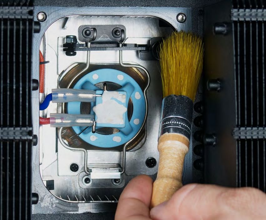
CONTENTS

     General Information                4

     Warranty Returns (USA Only)        5

     Safety Guidelines                  6

     Discharge Lamp Warning             8

     Overview                           9

     Lamp Installation                  10

     Gobo Installation                  17

     Fixture Installation               26

     System Menu                        31

     E-FLY Wireless DMX Set Up          37

     DMX Channel Functions And Values   39

     Error Codes                        47

     Maintenance                        52

     Specifications                     53

     Optional Accessories               56

                                   3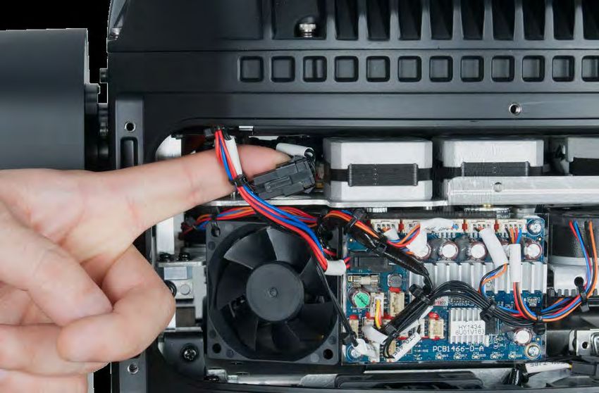
GENERAL INFORMATION
INTRODUCTION
Please read and understand the instructions in this manual carefully and thoroughly before attempting to
operate this device. These instructions contain important safety and use information.

COOLING
After usage, the lamp may be switched off, but the fixture should remain connected to power in order
to allow the fan time to cool down the fixture.

IP65 RATED
An IP rated lighting fixture is one, which is commonly installed in outdoor environments and has been
designed with an enclosure that effectively protects the ingress (entry) of external foreign objects such
as dust and water. The International Protection (IP) rating system is commonly expressed as "IP"
(Ingress Protection) followed by two numbers (i.e. IP65) where the numbers define the degree of
protection. The first digit (Foreign Bodies Protection) indicates the extent of protection against
particles entering the fixture and the second digit (Water Protection) indicates the extent of protection
against water entering the fixture. An IP65 rated lighting fixture is one, which has been designed and
tested to protect against the ingress of dust (6) and low-pressure water jets from any direction (5).

UNPACKING
Every device has been thoroughly tested and has been shipped in perfect operating condition.
Carefully check the shipping carton for damage that may have occurred during shipping. If the carton
is damaged, carefully inspect the device for damage, and be sure all accessories necessary to install
and operate the device have arrived intact. In the event damage has been found or parts are missing,
please contact our customer support team for further instructions. Please do not return this device to
your dealer without first contacting customer support. Please do not discard the shipping carton in
the trash. Please recycle whenever possible.

BOX CONTENTS
Omega Brackets (x2)
IP65 Rated 5pin DMX Cable
IP65 Rated RJ45 Cable (Fixture to Fixture Interconnect Use Only!)
IP65 Power Cable

CUSTOMER SUPPORT
Contact ELATION Service for any product related service and support needs. Also visit
forums.elationlighting.com with questions, comments, or suggestions.

ELATION SERVICE USA - Monday - Friday 8:00am to 4:30pm PST
323-582-3322 | Fax 323-832-9142 | support@elationlighting.com

ELATION SERVICE EUROPE - Monday - Friday 08:30 to 17:00 CET
+31 45 546 85 63 | Fax +31 45 546 85 96 | support@elationlighting.eu

REPLACEMENT PARTS please visit parts.elationlighting.com

                                                   4
WARRANTY RETURNS (USA ONLY)
To obtain warranty service, a Return Materials Authorization (RMA) number must first be obtained from
ELATION. It is the Customer’s responsibility to provide product proof of purchase and serial number by
acceptable evidence such as an invoice copy or an approved ELATION Extended Warranty Certificate
(“EWC”) and any relevant maintenance records at the time warranty service is sought. Failure to provide
acceptable evidence of product proof of purchase or EWC and any relevant maintenance records may be
cause for denial of warranty service.

Products returned for warranty service must be sent without any accessories (i.e., power, data, and
safety cables, brackets, clamps, rigging hardware, frost filters, gel frames, barn doors, lens, hoses,
nozzles, rack mounting hardware, etc.), must be boxed using the original and/or suitable packaging
materials (double-box and foam) that provides ample product protection for ground and/or air freight
transit, and must be shipped freight pre-paid and insured to ELATION in Los Angeles, CA or an
ELATION Authorized Service Center. The RMA number must be clearly written on the outside of the
return box, and a brief description of the problem and the RMA number must be documented and
included in the box.

Products returned for warranty service without an RMA number clearly marked on the outside of the
package will be refused and returned to the shipper at the Customer’s expense. Products returned for
warranty service, which are received damaged due to inadequate and/or improper packaging and/or
due to damage caused by shipping carrier, may incur additional repair charges before warranty service
begins and/or may void this warranty. If any product accessories (included and/or optional) are
shipped with the product, ELATION and/or the ELATION Authorized Service Center shall have no
liability whatsoever for the loss and/or damage to any such accessories, nor the safe return thereof. If
the requested warranty repairs or service (including parts replacement) are within the terms of this
warranty, ELATION will pay return ground transportation shipping charges to a single designated point
within the United States.

                                                   5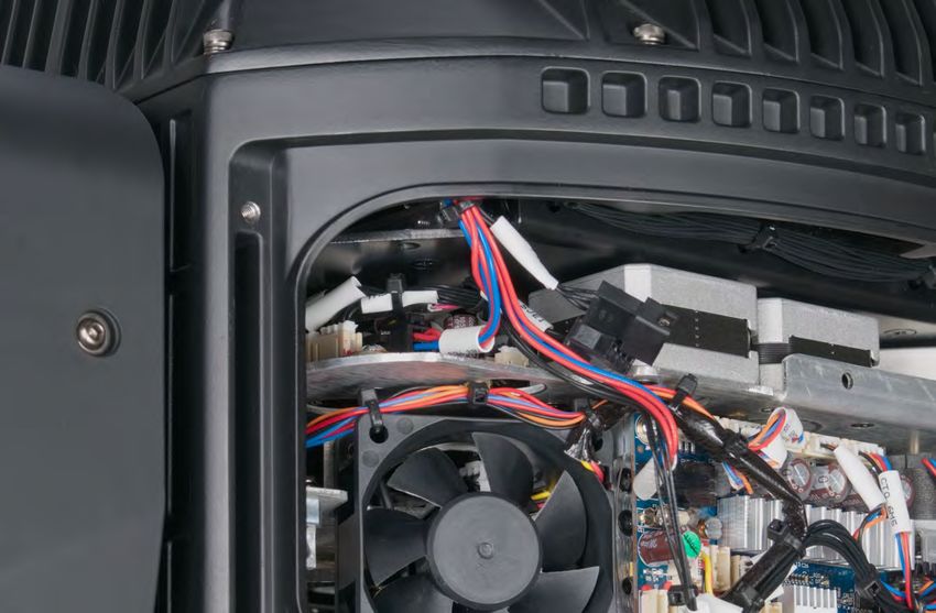
SAFETY GUIDELINES
To guarantee a smooth operation, it is important to follow all instructions and guidelines in this manual.
Elation Professional is not responsible for injury and/or damages resulting from the misuse of this
fixture due to the disregard of the information printed in this manual. Only qualified and/or certified
personnel should perform installation of this fixture and only the original rigging parts included with
this fixture should be used for installation. Any modifications to the fixture and/or the included
mounting hardware will void the original manufactures warranty and increase the risk of damage
and/or personal injury.

              PROTECTION CLASS 1 - FIXTURE MUST BE PROPERLY GROUNDED

              THERE ARE NO USER SERVICEABLE PARTS INSIDE THIS UNIT.
              DO NOT ATTEMPT ANY REPAIRS YOURSELF; DOING SO WILL VOID YOUR
              MANUFACTURES WARRANTY. DAMAGES RESULTING FROM
              MODIFICATIONS TO THIS FIXTURE AND/OR THE DISREGARD OF SAFETY
              INSTRUCTIONS AND GUIDELINES IN THIS MANUAL VOID THE
              MANUFACTURES WARRANTY AND ARE NOT SUBJECT TO ANY WARRANTY
              CLAIMS AND/OR REPAIRS.

              DO NOT PLUG FIXTURE INTO A DIMMER PACK!
              NEVER OPEN THIS FIXTURE WHILE IN USE!
              UNPLUG POWER BEFORE SERVICING FIXTURE!
              NEVER TOUCH FIXTURE DURING OPERATION, AS IT MAY BE HOT!
              KEEP FLAMMABLE MATERIALS AWAY FROM FIXTURE!

              ENSURE ALL CONNECTIONS AND END CAPS ARE PROPERLY SEALED WITH
              A DIELECTRIC GREASE (AVAILABLE AT MOST ELECTRICAL SUPPLIERS) TO
              PREVENT WATER CORROSION AND/OR ELECTRICAL SHORT CIRCUIT.

              IF THE FIXTURE IS EXPOSED TO ENVIRONMENTAL TEMPERATURE CHANGES
              SUCH AS RELOCATION FROM AN OUTDOOR COLD TO AN INDOOR WARM
              ENVIRONMENT, DO NOT POWER THE FIXTURE ON IMMEDIATELY. INTERNAL
              CONDENSATION AS A RESULT OF ENVIRONMENTAL TEMPERATURE CHANGE
              CAN CAUSE INTERNAL FIXTURE DAMAGE. LEAVE THE FIXTURE POWERED
              OFF UNTIL IT HAS REACHED ROOM TEMPERATURE BEFORE POWERING ON.

              NEVER LOOK DIRECTLY INTO THE LIGHT SOURCE!
              RETINA INJURY RISK - MAY INDUCE BLINDNESS!
              SENSITIVE PERSONS MAY SUFFER AN EPILEPTIC SHOCK!

              MINIMUM DISTANCE TO OBJECTS/SURFACES
              MUST BE 40 FEET (12 METERS)
              MAXIMUM TEMP OF EXTERNAL SURFACE 212° F (100°C)
              MINIMUM DISTANCE OF INFLAMMABLE MATERIALS
              FROM THE SURFACE 5.0 FEET (1.5 METER

                                                    6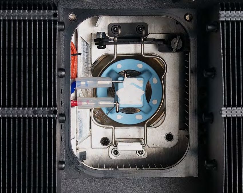
SAFETY GUIDELINES
                     RISK GROUP 3 - RISK OF EXPOSURE TO ULTRAVIOLET UV RADIATION!
                     FIXTURE EMITS HIGH INTENSITY WAVELENGTH OF ULTRAVIOLET UV
                     LIGHT FROM THE UV COLOR FILTER. WEAR PROPER EYE AND SKIN
                     PROTECTION. AVOID PROLONGED PERIODS OF EXPOSURE TO UV
                     COLOR FILTER. AVOID WEARING WHITE COLOR CLOTHING AND/OR
                     USING UV PAINTS ON SKIN. AVOID DIRECT EYE AND/OR SKIN EXPOSURE
                     AT DISTANCES LESS THAN 11 feet (3.3m). DO NOT OPERATE FIXTURE
                     WITH DAMAGED/MISSING EXTERNAL COVERS. DO NOT LOOK DIRECTLY
INTO THE UV LIGHT AND/OR VIEW UV LIGHT DIRECTLY WITH OPTICAL INSTRUMENTS THAT MAY
CONCENTRATE THE LIGHT/RADIATION OUTPUT. INDIVIDUALS SUFFERING FROM A RANGE OF
EYE CONDITIONS, SUNLIGHT EXPOSURE DIS-ORDERS, OR INDIVIDUALS USING
PHOTOSENSITIVE MEDICATION, MAY RECEIVE DISCOMFORT IF EXPOSED TO THE ULTRAVIOLET
UV LIGHT EMITTED FROM THE UV LED.
DO NOT TOUCH the fixture housing during operation. Turn OFF the power and allow approximately
60 minutes for the fixture to cool down before serving.
DO NOT shake fixture, avoid brute force when installing and/or operating fixture.
DO NOT operate fixture if the power cord is frayed, crimped, damaged and/or if any of the power cord
connectors are damaged and do not insert into the fixture securely with ease. NEVER force a power
cord connector into the fixture. If the power cord or any of its connectors are damaged, replace it
immediately with a new one of similar power rating.
DO NOT block any air ventilation slots.
All fan and air inlets must remain clean and never blocked.
Allow approx. 6” (15cm) between fixture and other devices or a wall for proper cooling.
Always disconnect fixture from main power source before performing any type of service and/or
cleaning procedure. Only handle the power cord by the plug end, never pull out the plug by tugging
the wire portion of the cord.
During the initial operation of this fixture, a light smoke or smell may emit from the interior of the fixture.
This is a normal process and is caused by excess paint in the interior of the casing burning off from the
heat associated with the lamp and will decrease gradually over time.
Consistent operational breaks will ensure fixture will function properly for many years.
ONLY use the original packaging and materials to transport the fixture in for service.

                                                      7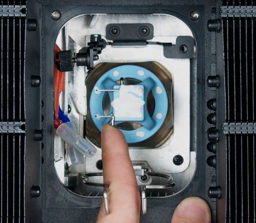
DISCHARGE LAMP WARNING
                   This fixture is fitted with a DISCHARGE LAMP, which is highly susceptible
                   to damage if improperly handled. NEVER touch the lamp with your bare
                   hands, as the oil from your hands will shorten the life of the lamp. Also,
                   NEVER move the fixture until the lamp has had ample time to cool. Lamps
                   are NOT covered under warranty conditions. Avoid switching the fixture ON
                   and OFF repeatedly in short intervals, as this will reduce lamp life and
                   intensity. To achieve the intensity associated with discharge lamps, these
                   lamps use gas sealed in a high-pressure environment to emit a brilliant
                   output.

Due to the high pressure involved with the construction of the lamp, the lamp MAY EXPLODE
DURING PROLONGED EXTENSIVE USE. This risk is increased with age; added care is
encouraged when dealing with older lamps. Thus, the lamp must always be replaced at the end
of their recommended duty cycle. Extreme caution should be used when operating this or any
fixture fitted with a gas discharge lamp.

                    U V      R A D I A T I O N               N O T I C E
                    This fixture emits intense UV radiation, which is harmful to the
                    eyes and skin. The intense luminance of the lamp can cause
                    severe damage to the retina. NEVER operate this fixture with
                    ANY of the protective covers removed. These covers have been
                    specially designed to shield against UV radiation.

                    L A M P            R E P L A C E M E N T
                    Please note that due to the nature of the Philips™ Platinum
                    21R Lamp and the optical path of the fixture, the lamp MUST
                    BE replaced at 1,500 hours.
                    Use only Genuine Original Philips™ Platinum 21R Lamps.
                    Other brand lamps may cause damage and void warranty!

                                             8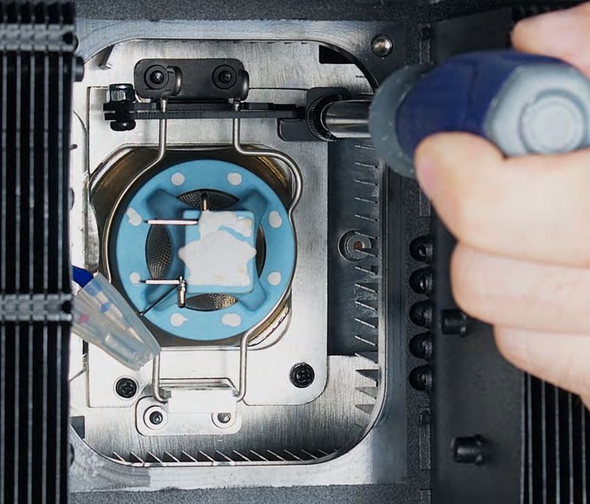
OVERVIEW

               1.   Lens
               2.   E-FLY Wireless DMX Indicator
                    LED
               3.   LCD Menu Control Display
               4.   MODE/ESC Button
               5.   LEFT Button
               6.   DOWN Button
               7.   ENTER Button
               8.   RIGHT Button
               9.   UP Button
               10. Power IN
               11. Fuse
               12. RJ45 Ethernet IN
               13. Gore Valve
               14. RJ45 Ethernet OUT
               15. 5pin DMX IN
               16. 5pin DMX OUT

           9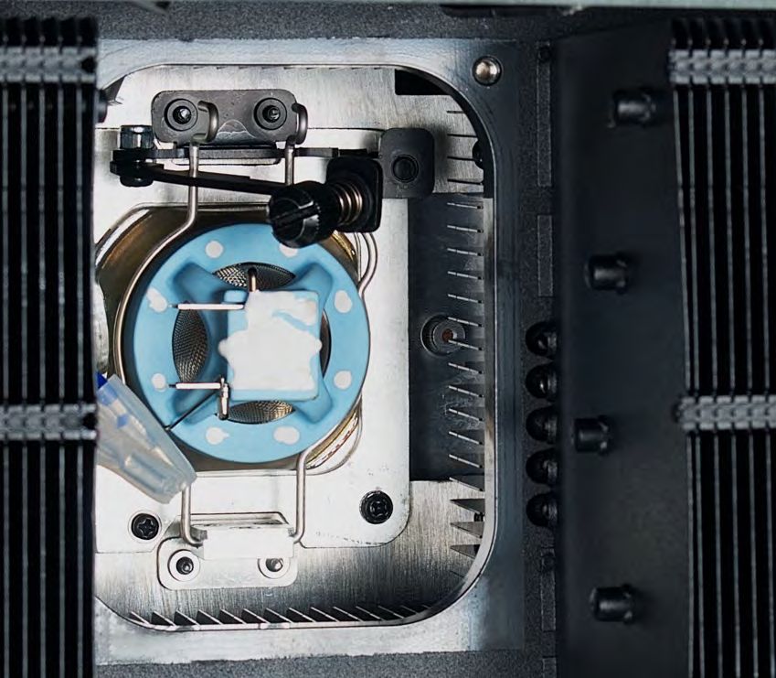
LAMP INSTALLATION

                        L A M P               R E P L A C E M E N T
                        Please note that due to the nature of the Philips™ Platinum
                        21R Lamp and the optical path of the fixture, the lamp MUST
                        BE replaced at 1,500 hours.
                        Use only Genuine Original Philips™ Platinum 21R Lamps.
                        Other brand lamps may cause damage and void warranty!

INSTALLING OR REPLACING THE LAMP
To ensure a proper/safe lamp change, carefully read all the following instructions.

LAMP PROTECTION CIRCUITRY
Because of the nature of the extreme heat associated with the Philips™ Platinum 21 R lamp and the
unique IP65 rated sealed optical system, it is IMPERATIVE that the lamp be replaced at 1,500 Hours
or sooner. This is done to protect the internal sealed optical system as well as prevent accidental lamp
explosion, which could lead to hot glass particles falling from the fixture.

FAILURE TO CHANGE THE LAMP WITHIN 300 HOURS of the 1,500 HOUR RATED LIFE, WILL
CAUSE THE FIXTURE TO AUTOMATICALLY SHUT DOWN!
At 1,500 Hours the LCD control display will begin to flash, “Replace The Lamp” and the lamp will
flicker for the first five minutes of operation. At this point the lamp has reached the maximum rated life
and should be replaced immediately. After the lamp has flickered for about five minutes it should strike
normally allowing the fixture to be used temporarily until a replacement lamp can be installed. The
fixture will continue to operate for an additional 300 hours; however, the “Replace the Lamp” warning
will continue to flash in the display. Keep in mind that the flicker protection circuitry will only work for
about 300 Hours (lamp clock life of 1,500-1,800 Hours).

After 1,800 Hours the fixture will no longer respond to DMX commands and immediately enter a
hibernation mode that will electronically discontinue all fixture functionality with the exception of a few
menu commands. The fixture will continue to enter hibernation mode until the lamp is replaced and
the lamp clock has been reset. To replace the lamp, follow the safety guidelines and procedures listed
on the next page.

                                                     10
LAMP INSTALLATION
WARNING! LAMP REPLACEMENT SHOULD ONLY BE DONE BE A TRAINED TECHNICIAN.
1. Turn OFF power and allow approximately 60 minutes for the fixture to cool down.
TILT
Lock
PAN
Lock
2. Place head in a right-angle horizontal position and engage both the PAN and TILT locks for added
stability while replacing the lamp.
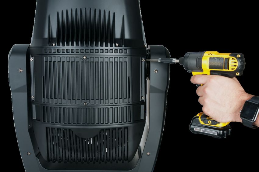
3. Remove (4x) 3mm hex-head screws to remove rear cover.
11LAMP INSTALLATION
4. Unclip the rear cover safety cable.
5. Remove (4x) 3mm hex-head screws holding the
center heatsink module.
6. Unclip the center heatsink module safety cable.
12LAMP INSTALLATION
7. Gently remove the (2x) spade terminals connected to the lamp.
8. Loosen the lamp retaining arm screw and the pull arm out. Then unclip the lamp retaining clip
13LAMP INSTALLATION
9. Swing the lamp retaining clip out, then carefully remove the lamp.
WARNING! LAMP MAY BE HOT. USE CAUTION WHEN TOUCHING LAMP WITH BARE HANDS.
10. Carefully install the new lamp then follow the removal instruction steps in reverse order.
NOTE: Brush away any debris using a nonabrasive brush before replacing the heatsink.
14LAMP INSTALLATION
G A S K E T I N S P E C T I O N
CAREFULLY REMOVE ANY DEBRIS FOUND ON GASKET AND SCREW HOLES OF THE
HEATSINK MODULE USING A NONABRASIVE BRUSH BEFORE INSTALLING!
CAREFULLY INSPECT HEATSINK GASKET FOR SIGNS OF WEAR SUCH AS CRACKING OR
HARDENING, DEFORMITIES, OR ALIGNMENT ISSUES BEFORE INSTALLING!
ITEMS ABOVE CAN IMPEDE THE IP65 INTEGRITY AND/OR CAUSE INTERNAL DAMAGE.
CONTACT ELATION SERVICE REGARDING GASKET REPLACEMENT IF NEEDED.
15LAMP INSTALLATION
T O R Q U E S E T T I N G S F O R S C R E W S
HEATSINK MODULE SCREWS MUST BE TIGHTENED WITH A TORQUE WRENCH.
The (4x) hex-head screws holding the heatsink module MUST be tightened with a torque
wrench. (not included) TORQUE SETTING = 11 lbf-in. (12.7kgf-cm) *
* lbf-in = Pound Force Inches | kgf-cm = Kilogram Force Centimeters
CAUTION! DO NOT OVER TORQUE SCREWS AS THIS CAN CAUSE LEAKAGE
ISSUES!
TO CONFIRM THE IP65 INTEGRITY AFTER A LAMP REPLACEMENT, TEST FIXTURE USING
THE ELATION IP TESTER. CONTACT ELATION SERVICE FOR MORE DETAILS.
16GOBO INSTALLATION
WARNING! GOBO REPLACEMENT SHOULD ONLY BE DONE BE A TRAINED TECHNICIAN.
1. Turn OFF power and allow approximately 60 minutes for the fixture to cool down.
TILT
Lock
PAN
Lock
2. Place the head in an upright vertical position and engage both the PAN and TILT locks for
added stability while replacing the gobo.
3. Remove (12x) 3mm hex-head screws (6x per panel) to remove both center panels.
17GOBO INSTALLATION
4. Unclip the panel safety cable one side of the head.
5. Unclip the panel safety cable on the opposite side of the head.
18GOBO INSTALLATION
6. Cut the plastic cable-ties holding wires and disconnect connectors attached to the effect module.
6a 6b
6c 6d
6e 6f
19GOBO INSTALLATION
7. Remove (2x) #2 Philips screws securing effect module. 8. Gently lift GOBO lens away from effect module.
9. Carefully remove the effect module from fixture. 10. Place the effect module on firm clean surface
and locate GOBO to replace.
11. Carefully lift the GOBO Holder up and out from the GOBO wheel using small needle nose plyers.
CAUTION! DO NOT SCRATCH GOBO AND HOLDER WHEN REPLACING!
20GOBO INSTALLATION
12. Carefully remove retaining spring. CAUTION! DO NOT SCRATCH GOBO OR GOBO HOLDER!
13. Carefully separate the GOBO disc from the GOBO Holder.
14. Carefully remove the retaining ring washer attached to the GOBO.
SAVE RETAINING RING WASHER FOR USE WITH THE NEW REPLACEMENT GOBO!
RETAINING RING MUST BE USED IN ORDER TO PREVENT GOBO BURNING!
15. Carefully replace the GOBO and GOBO Holder following the instruction steps in reverse order.
NOTE: Brush away any debris using a nonabrasive brush before installing the effect module.
21GOBO INSTALLATION
G A S K E T I N S P E C T I O N
CAREFULLY REMOVE ANY DEBRIS FOUND ON GASKET AND SCREW HOLES OF BOTH
CENTER PANELS USING A NONABRASIVE BRUSH BEFORE INSTALLING!
CAREFULLY INSPECT GASKETS FOR SIGNS OF WEAR SUCH AS CRACKING OR HARDENING,
DEFORMITIES, OR ALIGNMENT ISSUES BEFORE INSTALLING!
ITEMS ABOVE CAN IMPEDE THE IP65 INTEGRITY AND/OR CAUSE INTERNAL DAMAGE.
CONTACT ELATION SERVICE REGARDING GASKET REPLACEMENT IF NEEDED.
22GOBO INSTALLATION
T O R Q U E S E T T I N G S F O R S C R E W S
PANEL SCREWS MUST BE TIGHTENED WITH A TORQUE WRENCH.
The (12x) hex-head screws holding the panels MUST be tightened with a torque wrench.
(not included) TORQUE SETTING = 11 lbf-in. (12.7kgf-cm) *
* lbf-in = Pound Force Inches | kgf-cm = Kilogram Force Centimeters
CAUTION! DO NOT OVER TORQUE SCREWS AS THIS CAN CAUSE LEAKAGE ISSUES!
TO CONFIRM THE IP65 INTEGRITY AFTER A GOBO REPLACEMENT, TEST FIXTURE USING
THE ELATION IP TESTER. CONTACT ELATION SERVICE FOR MORE DETAILS.
23GOBO INSTALLATION
ROTATING GOBO SPECIFICATIONS
* * * IMPORTANT NOTICE REGARDING CUSTOM GOBOS * * *
Due to the extreme high temperature optical system, which can reach up to 842°F (450°C), special
BOROFLOAT glass material and design requirements are required. Due to varying gobo
manufacturing processes and tolerances, it is highly recommended to provide a gobo sample from
the fixture to the custom gobo vendor for accurate sizing. Extended testing of custom gobo designs
is highly recommended prior to using.
PLEASE CONTACT ELATION CUSTOMER SUPPORT FOR FURTHER INFORMATION
24GOBO INSTALLATION
CUSTOM GOBO DESIGN GUIDELINES
* * * IMPORTANT NOTICE REGARDING CUSTOM GOBO DESIGNS* * *
Full Color / Solid Area custom gobo designs are NOT RECOMMENDED due to the extreme high
temperature optical system which can reach up to 842°F (450°C).
Custom gobo designs as illustrated below can burn during extended use periods.
PLEASE CONTACT ELATION CUSTOMER SUPPORT FOR FURTHER INFORMATION
25FIXTURE INSTALLATION
FLAMMABLE MATERIAL WARNING
Keep fixture at least 5.0 feet (1.5m) away from any
flammable materials, decorations, pyrotechnics, etc.
ELECTRICAL CONNECTIONS
A qualified electrician should be used for all
electrical connections and/or installations.
MINIMUM DISTANCE TO OBJECTS/SURFACES
MUST BE 40 FEET (12 METERS)
MAXIMUM TEMPERATURE OF EXTERNAL SURFACE
212° F (100°C)
DO NOT INSTALL THE FIXTURE IF YOU ARE NOT QUALIFIED TO DO SO!
Fixture MUST be installed following all local, national, and country commercial electrical and
construction codes and regulations. Before rigging/mounting the fixture to any metal truss/structure
or placing the fixture on any surface, a professional equipment installer MUST be consulted to
determine if the metal truss/structure or surface is properly certified to safely hold the combined weight
of the fixture, clamps, cables, and accessories.
Overhead fixture installation must always be secured with a secondary safety attachment, such as an
appropriately rated safety cable that meets all local, national, and country codes and regulations.
Fixture ambient operating temperature range is -4° to 113°F. (-20° to 45°C)
Do not use this fixture outside this temperature range.
Fixture should be installed in areas outside walking paths, seating areas, or away from areas where
unauthorized personnel might reach the fixture by hand.
NEVER stand directly below the fixture when rigging, removing, or servicing.
Allow approximately 15 minutes for the fixture to cool down before serving.
26FIXTURE INSTALLATION
CLAMP INSTALLATION
The fixture can be attached to a metal truss/structure using. When mounting this fixture to truss be
sure to secure (2) appropriately rated clamps (not included) to the (2) Omega Brackets (included) Be
sure to attach the Safety Cable (included) to the fixture using the safety cable rigging point integrated
into the bottom of the fixture. (See image below)
SAFETY CABLE RIGGING POINT
S A F E T Y C A B L E
ALWAYS ATTACH A SAFETY CABLE
WHENEVER INSTALLING THIS DEVICE IN A
SUSPENDED ENVIRONMENT TO ENSURE
THE FIXTURE WILL NOT DROP IF THE
CLAMP FAILS.
27FIXTURE INSTALLATION
OVERHEAD RIGGING
Overhead rigging requires extensive experience, including amongst others calculating working load
limits, installation material being used, and periodic safety inspection of all installation material and
the fixture. If you lack these qualifications, do not attempt the installation yourself. Improper installation
can result in bodily injury.
Fixture is fully operational in the specific mounting positions illustrated below.
*SIDE MOUNTING *SAFETY CABLE
TO MAINTAIN IP65 RATING INTEGRITY, ALWAYS ATTACH A SAFETY CABLE
FIXTURE MUST BE INSTALLED WITH WHENEVER INSTALLING THIS FIXTURE
CABLES FACING DOWN TOWARDS THE IN A SUSPENDED ENVIRONMENT TO
GROUND AT ALL TIMES. WATER MUST ENSURE THE FIXTURE WILL NOT DROP
EASILY RUN OFF AND NOT COLLECT IF THE CLAMP FAILS.
AROUND CABLE CONNECTIONS.
28FIXTURE INSTALLATION
CONNECTIONS
ENSURE ALL CONNECTIONS AND END CAPS ARE PROPERLY SEALED
WITH A DIELECTRIC GREASE (AVAILABLE AT MOST ELECTRICAL
SUPPLIERS) TO PREVENT WATER CORROSION AND/OR ELECTRICAL
SHORT CIRCUIT.
TO MAINTAIN IP65 RATING INTEGRITY, AND PREVENT WATER FROM
ENTERING THE FIXTURE, ALL UNUSED CONNECTION RUBBER CAPS
MUST BE SEALED.
INCLUDED RJ45 DATA CABLE
THE INCLUDED RJ45 DATA CABLE IS FOR FIXTURE-TO-FIXTURE INTERCONNECT
ONLY! THE RJ45 CABLE CONNECTORS MAY NOT BE COMPATIBLE WITH OTHER
RJ45/ETHERCON TYPE CONNECTORS.
29FIXTURE INSTALLATION
POTENTIAL INTERNAL FIXTURE DAMAGE FROM EXTERNAL SOURCES OF LIGHT
BEAMS
External sources of light beams from direct sunlight, lighting moving head fixtures, and lasers, which
are focused directly on the exterior housing and/or penetrate the front lens opening of ELATION
lighting fixtures, can cause severe internal damage including burning to optics, dichroic color filters,
glass and metal gobos, prisms, animation wheels, frost filters, iris, shutters, motors, belts, wiring,
discharge lamps, and LEDs.
This issue is not specific only to ELATION lighting fixtures, it is a common issue with lighting fixtures
from all manufacturers. Although there is no true way to fully prevent this issue from happening, the
guidelines below can prevent any potential damage from occurring if followed. Contact ELATION
Service for more details.
DO NOT EXPOSE THE FIXTURE AND/OR
FRONT LENS OPENING TO LIGHT BEAMS
FROM DIRECT SUNLIGHT, OTHER LIGHTING
MOVING HEAD FIXTURES, AND LASERS
WHILE UNPACKING, INSTALLATION, USE,
AND EXTENDED IDLE TIMES OUTDOORS. DO
NOT FOCUS A LIGHT BEAM FROM ONE
LIGHTING FIXTURE DIRECTLY TOWARDS
ANOTHER.
SUN PROTECTION MODE / HIBERNATION MODE
This state can be set via DMX, or will go into
this state after 3 minutes without a DMX signal.
When the sun protection is activated, the pan-
and-tilt function of the moving-head will position
the lens away from direct sunlight, or other high
intensity light source, to protect the internal
belts, electronics etc. from burn damage.
When the unit is in the ‘sun protection state’, it
uses its accelerometer sensors (X-Y-Z) (only
present on discharge units and IP units) to
position the front lens downwards, even when
the unit(s) will be moved from its position. This
will keep on changing the position of the head.
Note that ‘manual mode’ overrides the ‘sun-protection mode’.
The hibernation function is an incredibly old feature that puts the unit into a ‘sleep state’ to save power
(this is a state whereas only the electronics remain on, and all other functions are turned off, functions
such as motors lamps etc.). This state is automatically activated when no DMX signal is present for
the set time (1-99min or off).
30SYSTEM MENU
The fixture includes an easy to navigate system menu control panel display where all necessary setting
adjustments are made. (See image below) During normal operation, pressing MODE/ESC button once
will access the fixture’s main menu. Once in the main menu you can navigate through the different
functions and access the sub-menus with the UP, DOWN, RIGHT, and LEFT buttons. Once you reach
a field that requires adjusting, press the ENTER button to activate that field and use the UP and DOWN
buttons to adjust the field. Pressing the ENTER button once more will confirm your setting. You may
exit the main menu at any time without making any adjustments by pressing the MODE/ESC button.
NOTE: To access the LCD Menu Control Display via the internal battery, press and hold the
MODE/ESC button for 10 seconds. The LCD Menu Control Display will shut OFF automatically about
60 seconds from the last button press.
31S Y S T E M M E N U
Supports Software Versions: ≥ 1.3.1A
Features are subject to change without any prior written notice.
*Rotation direction (Clockwise or Counterclockwise) of effects depends on orientation of the fixture head and Pan/Tilt settings.
MAIN MENU SUB MENU OPTIONS / VALUES (Default Settings in BOLD) DESCRIPTION
Set Dmx Address A001~AXXX DMX Address Setting
Dmx Value ALL…… DMX Value Display
FUNCTION Secondary Mode Secondary1, Secondary2, Secondary3 Secondary Setting
Auto Program Primary / Alone Auto Program
Current Time XXXX (Hours) Fixture Run Time From Power ON
Total Run Time XXXX (Hours) Fixture Total Run Time
Last Run Time XXXX (Hours) Fixture Last Run Time
Lamp Hours XXXX (Hours) Lamp Running Time
Time Information Lamp Off Time XXXX (Hours) Lamp Off Time
LastRun Password Password=038 (PSWD Required)
Clear Last Run ON / OFF Clear Fixture Last Run Time
LampTime Password Password=038 (PSWD Required)
Clean Lamp Time ON / OFF Clear Lamp Last Run Time
Head Temperature XXX C° / F ° Temperature in Fixture Head
INFORMATION
Temperature Info LAMP Temperature XXX C° / F ° Temperature of LAMP
Base Temperature XXX C° / F ° Temperature in Fixture Base
Base Humidity XXX%RH Humidity In Fixture Base
Humidity Info
Head Humidity XXX%RH Humidty in Fixture Head
Ethernet IP XXX . XXX . XXX . XXX XXX . XXX . XXX . XXX Displays Fixture Ethernet Address
Fan Info 1U_FAN1.... RPM Speeds of Fans
Encode Info PAN ENCODE:, TILT ENCODE:...
Software Version ≥V1.3.1A Software Version
Error Info Error Record 1 ~ Error Record 10 Fixture Last 10 Error Codes
Lamp Error log Error Record 1 ~ Error Record 10 Lamp Last 10 Error Codes
Lamp ON/OFF ON/OFF Lamp ON/OFF
Automatic ON ON/OFF Lamp ON/OFF when Power ON
Lamp ON via DMX ON/OFF Lamp ON via DMX
LAMP
Lamp OFF via DMX ON/OFF Lamp OFF via DMX
CONTROL
Max ON at Temp 20~79°C (45°C) / 68 ~ 174°F (113°F) Lamp Restart at Temp
MaxOnatHumidity 20~100%RH, 70%RH Fixture Restart at Humidity
Lamp OFF Temp 80~139°C (130°C) / 176 ~ 282°F (266°F) Lamp OFF at Temp
SYSTEM MENU CHANGE WITH SOFTWARE UPDATE VERSION ≥1.6.4
• Reset behavior changed with dim up/down.
• End of lamp life behavior changed without a strobing light
• RDM over artnet change bug solved (channel mode switched back after a powercycle).
• Lamp on/Off temp settings removed and set to max 135C off temp.
• When lamp off 4 internal fans keep running to cool the unit internally and avoid condensation on inner lens.
(in hibernation mode fans stop running).
See highlighted menu items below which have been updated with this software update.
Lamp ON/OFF ON/OFF Lamp ON/OFF
Automatic ON ON/OFF Lamp ON/OFF when Power ON
LAMP
Lamp ON via DMX ON/OFF Lamp ON via DMX
CONTROL
Lamp OFF via DMX ON/OFF Lamp OFF via DMX
MaxOnatHumidity 20~100%RH, 70%RH Fixture Restart at Humidity
32SYSTEM MENU CHANGE WITH SOFTWARE UPDATE VERSION ≥1.6.5
• RDM issues solved and break time changed.
• Special “Home Position” (Sun Protection) settings added in the “speed pan/tilt movement” channel to avoid
sun coming into the lens and destroy the fans, sliders, belts etc:
• The lens will be pointed down as best as possible.
This "Home position"(sun-protection) will be active in the following situations:
1. when it is set to ON in the "Speed Pan/Tilt movement" channel.
2. when the unit loses DMX, it will enter the homing position after 3-minutes.
3. when the lamp is set OFF.
SYSTEM MENU CHANGE WITH SOFTWARE UPDATE VERSION ≥1.6.6
• Sun-Protection Active added to display
• Hibernation-Active added to display
• Sun-protection manual overwrite added
• Sun-Protection pan/tilt movement slowed down during activation
• Display lock count-up added to the display
33S Y S T E M M E N U
Supports Software Versions: ≥ 1.3.1A
Features are subject to change without any prior written notice.
*Rotation direction (Clockwise or Counterclockwise) of effects depends on orientation of the fixture head and Pan/Tilt settings.
MAIN MENU SUB MENU OPTIONS / VALUES (Default Settings in BOLD) DESCRIPTION
Address via DMX ON/OFF Address Via DMX
No DMX Status Close / Hold / Auto Fixture State When NO DMX Signal
Pan Reverse ON/OFF Pan Reverse Movement
Tilt Reverse ON/OFF Tilt Reverse Movement
Status Settings Pan Degree 630/540 Pan Degree Select
Feedback ON/OFF Movement Feedback
NormalSpeed
Movement Speed Select Movement Speed
SlowSpeed
Hibernation OFF, 01M~99M, 15M Stand By Mode
Password Password=050 Service Password
RDM PID 22A6xxxxxxxx RDM PID Code (PSWD Required)
Service Setting
Clear Err. Info ON/OFF Clear Error Info (PSWD Required)
DFLT Pow. LampOn ON/OFF Set Default Lamp Power State to ON
PERSONALITY Shutoff Time 02~60m 05m LCD Display Shut Off Time
Display Setting Display Reverse AUTO/ON/OFF LCD Display Reverse 180º
Key Lock ON/OFF LCD Control Panel Lock Out
Temperature C/F Celsius/Fahrenheit Temperature Switch Between C˚/ F˚
Initial Status CONTROL =XXX Initial Effect Position
E-FLY Off Control via DMX ONLY
DMX & E-FLY Control via DMX and E-FLY
Select Signal E-FLY & OUT Control via E-FLY and sends DMX Out
Art-Net Control via Art-Net Protocol
sACN Control via sACN Protocol
Set Universe 000 - 32767 Set ArtNet Universe (Art-Net 4)
Ethernet IP XXX.XXX.XXX.XXX Set Fixture IP Address
Ether Mask IP XXX.XXX.XXX.XXX Set Fixture Subnet Mask Address
Set E-FLY Chn 00 - 15 Set E-FLY Wireless Channel
Reset Default ON/OFF Password=011 Restore Factory Settings (PSWD Required)
SYSTEM MENU CHANGE WITH SOFTWARE UPDATE VERSION ≥1.6.0
See highlighted menu items below which have been updated with this software update.
MAIN MENU SUB MENU OPTIONS / VALUES (Default Settings in BOLD) DESCRIPTION
HighSpeed
Status Settings Movement Speed MiddleSpeed Select Movement Speed
SlowSpeed
HighSpeed
FocusZoom Speed Select Focus Zoom Speed
Slow Speed
Password Password=050 Service Password
PERSONALITY RDM UID 22A6xxxxxxxx RDM PID Code (PSWD Required)
Service Setting
Clear Err. Info ON/OFF Clear Error Info (PSWD Required)
Clear Error code ON/OFF Clear Error Code (PSWD Required)
Initial Status Control =XXX Initial Effect Position
E-FLY Off Control via DMX ONLY
DMX & E-FLY Control via DMX and E-FLY
Select Signal E-FLY & OUT Control via E-FLY and sends DMX Out
Art-Net Control via Art-Net Protocol
sACN Control via sACN Protocol
34S Y S T E M M E N U
Supports Software Versions: ≥ 1.3.1A
Features are subject to change without any prior written notice.
*Rotation direction (Clockwise or Counterclockwise) of effects depends on orientation of the fixture head and Pan/Tilt settings.
MAIN MENU SUB MENU OPTIONS / VALUES (Default Settings in BOLD) DESCRIPTION
Reset All Reset All Motors
Reset Pan&Tilt Reset Pan/Tilt
Reset Reset Colors Reset Color Wheel
Function Reset Gobos Reset Gobos
Reset Shutter Reset Shutter
Reset Others Reset Other Motors
Test Channel CONTROL …… Test function
Effect Adjust Manual Control CONTROL =XXX, ...... Fine Adjustments
Calibration Calibration Password Password=050 Password 050 (PSWD Required)
Basic Mode
Standard Mode DMX Channel Modes
Extended Mode
User Mode
User Mode A
User Mode
User Mode B User Defined Channel Assignment
Set
User Mode C
Edit User Mode A
Max Channel = XX Edits User Defined
Edit User Mode B
PAN = CH01 Channel Assignments
Edit User Mode C
Auto Pro Part1 = Program 1~10 (Program 1)
Select Program Auto Pro Part2 = Program 1~10 (Program 2) Select Programs To Be Run
Auto Pro Part3 = Program 1~10 (Program 3)
Program 1 Program Test Testing Program
Edit Program : Step 01=SCxxx Program In Loop
Edit Program Program 10 Step 64=SCxxx Save and Exit
Pan,Tilt,…… Save and Automatically Return
Scene 001
--Fade Time--
Edit Scenes ~ Manual Scenes Edit
--Scene Time--
Scene 250
Input By Outside Stores Scenes via Ext DMX Console
Rec. Controller XX~XX Automatic Scenes Recorder
35PERSONALITY - Status Settings - Address Via DMX
When ON, define the desired DMX address via an external controller.
NOTE: This process assumes the fixture DMX address is set to 001. If fixture DMX address is not at 001, you must
adjust the channel numbers accordingly in order for this feature to work.
For example: if your fixture address is 010, then Channel 1 becomes Channel 10, Channel 2 becomes Channel 11,
and Channel 3 becomes Channel 12.
1. Connect the fixture to the external controller and power ON.
2. Set the DMX value of Channel 1 on the controller to (7).
3. Set the DMX value of Channel 2 on the controller to (7) or (8).
When set to (7), the DMX address can be set between (1) and (255).
When set to (8), the DMX address can be set between (256) and (511).
4. Using Channel 3 on the controller set the desired DMX address of the fixture.
Example 1: If the desired DMX address is 57, set Channel 1 to a value of (7), set Channel 2 to a
value of (7), and then set Channel 3 to a value of (57).
Example 2: If the desired DMX address is 420, set Channel 1 to a value of (7), set Channel 2 to a
value of (8), and then set Channel 3 to a value of (164). (256+164=420)
5. After setting Channel 3 to the desired DMX address value, wait for approximately 20 seconds
(some fixtures may require a longer time) for the fixture to complete the address reset function.
PERSONALITY - Reset Default (011)
ONLY QUALIFIED TECHNICIANS SHOULD PERFORM THIS FUNCTION.
NOTE: SAVED WHITE BALANCE IS ERASED AFTER A RESET IS PERFORMED.
This function restores all fixture settings to the factory default settings. The password is 011
and must be entered each time a reset is performed.
EFFECT ADJUST – Test Channel
Auto test each individual channel function independently from the DMX control board.
EFFECT ADJUST – Manual Control
Select and manually test and fine adjust each individual channel function
Independently from DMX control board. This function will center PAN and TILT motors and set dimmer
to 100%. PAN and TILT functions will still operate if the fixture needs to be positioned to a flat clear
surface. With the individual functions, you can focus the light on a flat surface (wall) and perform fine
adjustments.
EFFECT ADJUST – Calibration
ONLY QUALIFIED TECHNICIANS SHOULD PERFORM THIS FUNCTION.
This function allows small adjustments to be made to the Pan, Tilt, and Zoom movements to
compensate for ware or in the event a sensor has been knocked slightly out of place. Because
improper use of this function can result in undesired operation this function has been password
protected. The password is 050 and must be entered each time the calibration menu function is
entered. Because calibration is an extremely delicate procedure, instructions on performing this action
are left out of this manual. For a first-time calibrator, please contact our customer support team for
step-by-step instructions.
36E-FLY WIRELESS DMX SET UP
BEFORE SETTING THE WIRELESS CHANNEL ON ANY E-FLY FIXTURE,
MAKE SURE THE SOURCE E-FLY WIRELESS DMX TRANSCEIVER DEVICE
IS OFF. TO CONTROL FIXTURE WITH E-FLY WIRELESS DMX SIGNAL
1. Ensure the source E-FLY wireless DMX Transceiver device is powered OFF.
2. Power ON fixture and from the LCD control panel select DMX & E-FLY or E-FLY & OUT in the Select
Signal sub menu of the PERSONALITY main system menu.
3. From the LCD control panel set the E-FLY wireless channel to the same wireless channel of the source
E-FLY DMX Transceiver device in the Set E-FLY Chn sub menu of the PERSONALITY main system menu.
NOTE: Erratic fixture movement may occur if other E-FLY wireless DMX products are in use in the same area
and are using the same E-FLY wireless channel. The fixture may immediately start to respond to the DMX
wireless signal from another E-FLY wireless DMX Transceiver immediately when E-FLY is enabled. Make sure
to know what E-FLY wireless channels are being used in the area where the fixture is being installed.
ELATION E-FLY WIRELESS TRANSCEIVER only has 0-14 wireless channels, NO CH 15.
4. Set fixture DMX address in the Set Dmx Address sub menu of the FUNCTION main system menu.
5. The E-FLY signal Indicator on the fixture LCD control display will illuminate GREEN if a successful
wireless DMX connection has been made or illuminate RED for NO connection. If no connection is
made, repeat steps 1-4 above.
6. Repeat this process for all E-FLY compatible fixtures in the E-FLY wireless network, making sure
all fixtures are assigned the same E-FLY wireless channel.
7. After all fixtures in the E-FLY wireless network have been set to the same E-FLY wireless channel
and powered ON, now power ON the source E-FLY DMX Transceiver device.
8. Test all fixtures connected to the E-FLY wireless network to confirm proper functionality.
37WIRELESS E-FLY INSTALLATION LOCATION GUIDELINES
Wireless DMX signal can penetrate walls, glass, metal, and most objects. However, there are many
factors that can affect and/or interrupt the wireless DMX signal, one of which is people. Therefore, it
is highly recommended to position the wireless antenna a minimum of 9.8 ft. (3m) above audiences
and/or above ground level. Careful planning and testing of the selected installation location is critical
to ensure optimum and reliable wireless DMX operation.
38DMX CHANNEL FUNCTIONS AND VALUES
E L A T I O N P R O T E U S H Y B R I D
DMX Channel Values / Functions (37 DMX Channels)
Supports Software Versions: ≥ 1.3.1
Features subject to change without any prior written notice.
*Rotation direction (Clockwise or Counterclockwise) of effects depends on orientation of the fixture head and Pan/Tilt settings.
MODE / CHANNEL
VALUE FUNCTION
BASIC STAND EXTEND
PAN MOVEMENT
1 1 1
0-255 PAN Movement
PAN FINE MOVEMENT [16 BIT]
2 2
0-255 Fine Control of PAN Movement
TILT MOVEMENT
2 3 3
0-255 TILT Movement
TILT MOVEMENT [16 BIT]
4 4
0-255 Fine Control of TILT Movement
CYAN COLOR
3 5 5
0-255 0-WHITE ~ 255-100% CYAN
CYAN COLOR FINE [16 BIT]
6
0-255 CYAN FINE Adjustment
MAGENTA COLOR
4 6 7
0-255 0-WHITE ~ 255-100% MAGENTA
MAGENTA COLOR FINE [16 BIT]
8
0-255 MAGENTA FINE Adjustment
YELLOW COLOR
5 7 9
0-255 0-WHITE ~ 255-100% YELLOW
YELLOW COLOR FINE [16 BIT]
10
0-255 YELLOW FINE Adjustment
CTO COLOR
6 8 11
0-255 0-WHITE ~ 255-100% CTO
CTO COLOR FINE [16 BIT]
12
0-255 CTO FINE Adjustment
COLOR WHEEL
0-15 OPEN / WHITE
16-23 RED
24-31 BLUE
32-39 GREEN
40-47 YELLOW
48-55 PURPLE
56-63 AQUA
64-71 ORANGE
7 9 13 72-79 LIGHT PINK
80-87 LIME GREEN
88-95 LIGHT YELLOW
96-103 MAGENTA
104-111 CTB
112-119 CTO
120-127 UV
128-189 *Counterclockwise COLOR Rotation from FAST to SLOW
190-193 NO Rotation
194-255 *Clockwise COLOR Rotation from SLOW to FAST
39Supports Software Versions: ≥ 1.3.1
Features subject to change without any prior written notice.
*Rotation direction (Clockwise or Counterclockwise) of effects depends on orientation of the fixture head and Pan/Tilt settings.
MODE / CHANNEL
VALUE FUNCTION
BASIC STAND EXTEND
COLOR WHEEL FINE ADJUSTMENT [16 BIT]
14
0-255 FINE Adjustment of Color Wheel to Any Position
ROTATING GOBOS, CONTINUOUS ROTATION [GOBO WHEEL 1]
0-10 BEAM MODE OPEN
11-21 SPOT MODE OPEN
22-31 Rotating Gobo 1
32-41 Rotating Gobo 2
42-51 Rotating Gobo 3
52-61 Rotating Gobo 4
62-71 Rotating Gobo 5
72-81 Rotating Gobo 6
82-91 Rotating Gobo 7
92-101 Rotating Gobo 8
8 10 15
102-112 Gobo 1 Shake SLOW to FAST
113-123 Gobo 2 Shake SLOW to FAST
124-134 Gobo 3 Shake SLOW to FAST
135-145 Gobo 4 Shake SLOW to FAST
146-156 Gobo 5 Shake SLOW to FAST
157-167 Gobo 6 Shake SLOW to FAST
168-178 Gobo 7 Shake SLOW to FAST
179-189 Gobo 8 Shake SLOW to FAST
190-221 *Clockwise Gobo Wheel Rotation from FAST to SLOW
222-223 NO Rotation
224-255 *Counterclockwise Gobo Wheel Rotation from SLOW to FAST
ROTATING GOBOS, INDEX ROTATION [GOBO WHEEL 1]
0-127 Gobo Indexing
9 11 16 128-189 *Clockwise Gobo Rotation from FAST TO SLOW
190-193 NO Rotation
194-255 *Counterclockwise Gobo Rotation from SLOW to FAST
ROTATING GOBOS, FINE INDEX ROTATION [GOBO WHEEL 1] [16 BIT]
17
0-255 Gobo Rotation FINE Indexing
40Supports Software Versions: ≥ 1.3.1
Features subject to change without any prior written notice.
*Rotation direction (Clockwise or Counterclockwise) of effects depends on orientation of the fixture head and Pan/Tilt settings.
MODE / CHANNEL
VALUE FUNCTION
BASIC STAND EXTEND
STATIC / FIXED GOBOS [GOBO WHEEL 2]
0-7 OPEN
8-14 Static / Fixed Gobo 1
15-21 Static / Fixed Gobo 2
22-28 Static / Fixed Gobo 3
29-35 Static / Fixed Gobo 4
36-42 Static / Fixed Gobo 5
43-49 Static / Fixed Gobo 6
50-56 Static / Fixed Gobo 7
57-63 Static / Fixed Gobo 8
64-70 Static / Fixed Gobo 9
71-77 Static / Fixed Gobo 10
78-84 Static / Fixed Gobo 11
85-91 Static / Fixed Gobo 12
92-98 Static / Fixed Gobo 13
99-105 Static / Fixed Gobo 14
10 12 18 106-111 Shake SLOW to FAST Static / Fixed Gobo 1
112-117 Shake SLOW to FAST Static / Fixed Gobo 2
118-123 Shake SLOW to FAST Static / Fixed Gobo 3
124-129 Shake SLOW to FAST Static / Fixed Gobo 4
130-135 Shake SLOW to FAST Static / Fixed Gobo 5
136-141 Shake SLOW to FAST Static / Fixed Gobo 6
142-147 Shake SLOW to FAST Static / Fixed Gobo 7
148-153 Shake SLOW to FAST Static / Fixed Gobo 8
154-159 Shake SLOW to FAST Static / Fixed Gobo 9
160-165 Shake SLOW to FAST Static / Fixed Gobo 10
166-171 Shake SLOW to FAST Static / Fixed Gobo 11
172-177 Shake SLOW to FAST Static / Fixed Gobo 12
178-183 Shake SLOW to FAST Static / Fixed Gobo 13
184-189 Shake SLOW to FAST Static / Fixed Gobo 14
190-221 *Clockwise Gobo Wheel Rotation from FAST to SLOW
222-223 NO ROTATION
224-255 *Counterclockwise Gobo Wheel Rotation from SLOW to FAST
STATIC / FIXED GOBOS, FINE INDEX ROTATION [GOBO WHEEL 2] [16 BIT]
19
0-255 Gobo Rotation FINE Indexing
41Supports Software Versions: ≥ 1.3.1
Features subject to change without any prior written notice.
*Rotation direction (Clockwise or Counterclockwise) of effects depends on orientation of the fixture head and Pan/Tilt settings.
MODE / CHANNEL
BASIC STAND EXTEND
VALUE FUNCTION
ROTATING PRISM, PRISM / GOBO MACROS
0-31 OPEN
32-63 8-FACET PRISM
64-95 LINEAR PRISM
96-127 8-FACET + LINEAR PRISMS
128-135 Prism / Gobo Macro 1
136-143 Prism / Gobo Macro 2
144-151 Prism / Gobo Macro 3
152-159 Prism / Gobo Macro 4
160-167 Prism / Gobo Macro 5
11 13 20 168-175 Prism / Gobo Macro 6
176-183 Prism / Gobo Macro 7
184-191 Prism / Gobo Macro 8
192-199 Prism / Gobo Macro 9
200-207 Prism / Gobo Macro 10
208-215 Prism / Gobo Macro 11
216-223 Prism / Gobo Macro 12
224-231 Prism / Gobo Macro 13
232-239 Prism / Gobo Macro 14
240-247 Prism / Gobo Macro 15
248-255 Prism / Gobo Macro 16
DMX CHANGE WITH SOFTWARE UPDATE VERSION ≥1.5.0
See highlighted items below which have been updated with this software update.
Supports Software Versions: ≥ 1.5.0
Features subject to change without any prior written notice.
LL*Rotation direction (Clockwise or Counterclockwise) of effects depends on orientation of the fixture head and Pan/Tilt settings.
ROTATING PRISM, PRISM / GOBO MACROS
0-31 OPEN
32-64 8-FACET PRISM
65-94 LINEAR PRISM
95-127 8-FACET + LINEAR PRISMS
128-135 Prism / Gobo Macro 1
136-143 Prism / Gobo Macro 2
144-151 Prism / Gobo Macro 3
152-159 Prism / Gobo Macro 4
160-167 Prism / Gobo Macro 5
11 13 20 168-175 Prism / Gobo Macro 6
176-183 Prism / Gobo Macro 7
184-191 Prism / Gobo Macro 8
192-199 Prism / Gobo Macro 9
200-207 Prism / Gobo Macro 10
208-215 Prism / Gobo Macro 11
216-223 Prism / Gobo Macro 12
224-231 Prism / Gobo Macro 13
232-239 Prism / Gobo Macro 14
240-247 Prism / Gobo Macro 15
248-255 Prism / Gobo Macro 16
42Supports Software Versions: ≥ 1.3.1
Features subject to change without any prior written notice.
*Rotation direction (Clockwise or Counterclockwise) of effects depends on orientation of the fixture head and Pan/Tilt settings.
MODE / CHANNEL
VALUE FUNCTION
BASIC STAND EXTEND
ROTATING PRISM, PRISM INDEX ROTATION
0-127 Prism Indexing
12 14 21 128-189 *Clockwise Prism Rotation from FAST to SLOW
190-193 NO Rotation
194-255 *Counterclockwise Prism Rotation from SLOW to FAST
ROTATING PRISM, PRISM FINE INDEX ROTATION [16 BIT]
22
0-255 Gobo Rotation FINE Indexing
FOCUS
13 15 23
0-255 Continuous Adjustment from NEAR to FAR
FOCUS FINE [16 BIT]
24
0-255 Continuous FINE Adjustment
ZOOM
14 16 25
0-255 Continuous Adjustment from NEAR to FAR
ZOOM FINE [16 BIT]
26
0-255 Continuous FINE Adjustment
AUTO FOCUS
0-50 Auto Focus OFF
15 17 27
51-150 49 feet | 15m
151-255 65 feet | 20m
AUTO FOCUS FINE [16 BIT]
16 18 28
0-255 Auto Focus Continuous FINE Adjustment
SHUTTER, STROBE
0-31 Shutter CLOSED
32-63 NO Function (Shutter OPEN)
64-95 Strobe Effect SLOW to FAST
17 19 29 96-127 NO function (Shutter OPEN)
128-159 Pulse Effect In Sequences
160-191 NO Function (Shutter OPEN)
192-223 Random Strobe Effect SLOW to FAST
224-255 NO Function (Shutter OPEN)
DIMMER INTENSITY
18 20 30
0-255 Intensity 0 to 100%
DIMMER INTENSITY FINE [16 BIT]
31
0-255 Intensity 0 to 100%
FROST
19 21 32 0-127 Disable FROST
128-255 Enable FROST
ANIMATION WHEEL
0-7 CLOSE
20 22 33 8-127 *Clockwise Rotation FAST to SLOW
128-135 NO ROTATION
136-255 *Counterclockwise from SLOW to FAST
CMY SPEED
21 23 34
0-255 Speed MAX to MIN
43Supports Software Versions: ≥ 1.3.1
Features subject to change without any prior written notice.
*Rotation direction (Clockwise or Counterclockwise) of effects depends on orientation of the fixture head and Pan/Tilt settings.
MODE / CHANNEL
VALUE FUNCTION
BASIC STAND EXTEND
CMY MACROS
0-31 OFF
32-39 Macro 01
40-47 Macro 02
48-55 Macro 03
56-63 Macro 04
64-71 Macro 05
72-79 Macro 06
80-87 Macro 07
88-95 Macro 08
96-103 Macro 09
104-111 Macro 10
112-119 Macro 11
120-127 Macro 12
128-135 Macro 13
22 24 35
136-143 Macro 14
144-151 Macro 15
152-159 Macro 16
160-167 Macro 17
168-175 Macro 18
176-183 Macro 19
184-191 Macro 20
192-199 Macro 21
200-207 Macro 22
208-215 Macro 23
216-223 Macro 24
224-231 Macro 25
232-239 Macro 26
240-247 Macro 27
248-255 Random CMY
PAN / TILT MOVEMENT SPEED
0-225 MAX to MIN Speed
23 25 36 226-235 Blackout by Movement
236-245 Blackout by ALL Wheel Movement
246-255 NO FUNCTION
44Supports Software Versions: ≥ 1.3.1
Features subject to change without any prior written notice. *Rotation direction (Clockwise or Counterclockwise) of effects depends
on orientation of the fixture head and Pan/Tilt settings.
MODE / CHANNEL
VALUE FUNCTION
BASIC STAND EXTEND
LAMP ON/OFF, RESET, INTERNAL PROGRAMS
0-19 COLOR Change Normal
20-29 COLOR Change to Any Position
30-39 COLOR and FIXED GOBO Change to Any Position
40-59 LAMP ON
60-79 LAMP SWITCH OFF
80-84 ALL Motors Reset
85-87 SCAN Motor Reset
88-90 COLOR Motors Reset
91-93 GOBO Motors Reset
24 26 37
94-96 SHUTTER and DIMMER Motor Reset
97-99 OTHER Motors Reset
100-119 Internal Program 1
120-139 Internal Program 2
140-159 Internal Program 3
160-179 Internal Program 4
180-199 Internal Program 5
200-219 Internal Program 6
220-239 Internal Program 7
240-255 NO FUNCTION
45DMX CHANGE WITH SOFTWARE UPDATE VERSION ≥1.6.2
See highlighted items below which have been updated with this software update
Supports Software Versions: ≥ 1.6.2
Features subject to change without any prior written notice.
*Rotation direction (Clockwise or Counterclockwise) of effects depends on orientation of the fixture head and Pan/Tilt settings.
MODE / CHANNEL
BASIC STAND EXTEND
VALUE FUNCTION
LAMP ON/OFF, RESET, INTERNAL PROGRAMS
0-19 COLOR Change Normal
20-29 COLOR Change to Any Position
30-39 COLOR and FIXED GOBO Change to Any Position
40-59 LAMP ON
60-79 LAMP SWITCH OFF
80-84 ALL Motors Reset
85-87 SCAN Motor Reset
88-90 COLOR Motors Reset
91-93 GOBO Motors Reset
94-96 SHUTTER and DIMMER Motor Reset
97-99 OTHER Motors Reset
100-119 Internal Program 1
24 26 37
120-139 Internal Program 2
140-159 Internal Program 3
160-179 Internal Program 4
180-199 Internal Program 5
200-219 Internal Program 6
220-239 Internal Program 7
240-241 DIMMING STANDARD
242-243 DIMMING LINEAR
244-245 DIMMING SQUARE
246-247 DIMMING INVERSE SQUARE
248-249 DIMMING S-CURVE
250-255 RESERVED
240-255 NO FUNCTION
DMX CHANGE WITH SOFTWARE UPDATE VERSION ≥1.6.5
See highlighted items below which have been updated with this software update
Supports Software Versions: ≥ 1.6.5
Features subject to change without any prior written notice.
*Rotation direction (Clockwise or Counterclockwise) of effects depends on orientation of the fixture head and Pan/Tilt settings.
MODE / CHANNEL
VALUE FUNCTION
BASIC STAND EXTEND
PAN / TILT MOVEMENT SPEED
0-225 MAX to MIN Speed
226-235 Blackout by Movement
23 25 36 236-245 Blackout by ALL Wheel Movement
246-248 Home Position Before Power Off
249-251 Home Position Off
252-255 No Function
DMX CHANGE WITH SOFTWARE UPDATE VERSION ≥1.6.6
See highlighted items below which have been updated with this software update
Supports Software Versions: ≥ 1.6.6
Features subject to change without any prior written notice.
*Rotation direction (Clockwise or Counterclockwise) of effects depends on orientation of the fixture head and Pan/Tilt settings.
• Hibernation ON/OFF added to the DMX traits
46ERROR CODES
When power is applied, the unit will automatically enter a “Reset/Test” mode. This mode brings all
the internal motors to a home position. If there is an internal problem with one or more of the motors
an error code will flash in the display in the form of “XXer” were as XX will represent a function number.
For example, when the display shows “0Er” it means there is some type of error with the Pan motor.
If there are multiple errors during the start-up process, they will all flash in the display. For example: if
the fixtures have errors on Channel 1, 2, and 5 all at the same time, you will see the error message
“01Er”, “02Er”, and ”05Er” flash repeated 5 times.
If an error does occur during the initial start-up procedure the fixture will self-generate a second reset
signal and try to realign all the motors and correct the errors. If the error persists after a second attempt
a third attempt will be made. If after a third attempt all the errors have not been corrected the fixture
will make the following determinations:
• 3 or More Errors - The fixture cannot function properly with three or more errors therefore the
fixture will place itself in a stand-by mode until subsequent repairs can be made.
• Less Than 3 Errors - The fixture has less than 3 errors; therefore, most other functions will work
properly. The fixture will attempt to operate normally until the errors can be correct by a technician.
The errors in question will remain flashing in the display as a reminder of internal errors.
BALLAST ERROR NOTE
IF A BALLAST ERROR MESSAGE APPEARS, TURN THE LAMP OFF FOR 3-5 MINUTES TO
RESET THE BALLAST. IF AFTER 5-MINUTES A BALLAST ERROR STILL APPEARS, TURN THE
FIXTURE OFF TO RESET THE BALLAST. IF A BALLAST MESSAGE STILL APPEARS, PLEASE
CONSULT ELATION CUSTOMER SUPPORT.
47ERROR CODES
Error Codes are subject to change without any prior written notice.
ERROR CODES DESCRIPTION
PAN Er The PAN movement is not located in the default position after the reset.
This message will appear after a fixture reset if the magnetic-indexing circuit
malfunctions (sensor failed or magnet is missing) or there is a motor failure (defective
motor or a defective motor IC drive on the main PCB). This error may also be
displayed if the head/yoke was blocked during a reset function.
TILT Er The TILT movement is not located in the default position after the reset.
This message will appear after a fixture reset if the magnetic-indexing circuit
malfunctions (sensor failed or magnet is missing) or there is a motor failure (defective
motor or defective motor IC drive on main PCB). This error may also be displayed if
the head was blocked during a reset function.
Cyan The Cyan Color Wheel is not located in the default position after the reset.
This message will appear after the reset of the fixture reset if the magnetic-indexing
Wheel Er
circuit malfunctions (sensor failed or magnet is missing) or there is a stepper motor
failure (defective motor or defective motor IC drive on main PCB).
Magenta The Cyan Color Wheel is not located in the default position after the reset.
This message will appear after the reset of the fixture reset if the magnetic-indexing
Wheel Er
circuit malfunctions (sensor failed or magnet is missing) or there is a stepper motor
failure (defective motor or defective motor IC drive on main PCB).
Yellow The Yellow Color Wheel is not located in the default position after the reset.
This message will appear after the reset of the fixture reset if the magnetic-indexing
Wheel Er
circuit malfunctions (sensor failed or magnet is missing) or there is a stepper motor
failure (defective motor or defective motor IC drive on main PCB).
Color The Color Wheel is not located in the default position after the reset.
This message will appear after the reset of the fixture reset if the magnetic-indexing
Wheel Er
circuit malfunctions (sensor failed or magnet is missing) or there is a stepper motor
failure (defective motor or defective motor IC drive on main PCB).
CTO The CTO Color Wheel movement is not located in the default position after the reset.
This message will appear after a fixture reset if the gobo wheel’s magnetic-indexing
Wheel Er
circuit malfunctions (sensor failed or magnet is missing) or there is a stepper motor
failure (defective motor or defective motor IC drive on main PCB).
Rotating Gobo The Rotating Gobo Wheel movement is not located in the default position after the
reset. This message will appear after a fixture reset if the gobo wheel’s magnetic-
Wheel Er
indexing circuit malfunctions (sensor failed or magnet is missing) or there is a stepper
motor failure (defective motor or defective motor IC drive on main PCB).
48You can also read