IDOL: Inertial Deep Orientation-Estimation and Localization
←
→
Page content transcription
If your browser does not render page correctly, please read the page content below
IDOL: Inertial Deep Orientation-Estimation and Localization
                                                                                   Scott Sun, Dennis Melamed, Kris Kitani
                                                                                                Carnegie Mellon University
arXiv:2102.04024v1 [cs.RO] 8 Feb 2021

                                                                                                                         IMU Signal   Orientation     IMU        Position
                                                                    Abstract                                              Sequence     Module     Orientations   Module
                                                                                                                                                                            Location

                                          Many smartphone applications use inertial measurement
                                          units (IMUs) to sense movement, but the use of these sen-
                                          sors for pedestrian localization can be challenging due to
                                          their noise characteristics. Recent data-driven inertial odom-
                                          etry approaches have demonstrated the increasing feasibility
                                          of inertial navigation. However, they still rely upon conven-
                                          tional smartphone orientation estimates that they assume to
                                          be accurate, while in fact these orientation estimates can be a              Figure 1: Overview of our proposed method.
                                          significant source of error. To address the problem of inaccu-
                                          rate orientation estimates, we present a two-stage, data-driven
                                          pipeline using a commodity smartphone that first estimates
                                          device orientations and then estimates device position. The
                                                                                                               fectiveness. However, WiFi and Bluetooth beacon-based so-
                                          orientation module relies on a recurrent neural network and          lutions are costly due to requiring heavy instrumentation
                                          Extended Kalman Filter to obtain orientation estimates that          of the environment for accurate localization (Ahmetovic
                                          are used to then rotate raw IMU measurements into the appro-         et al. 2016). While LiDAR-based localization is highly ac-
                                          priate reference frame. The position module then passes those        curate, it is expensive and power-hungry (Zhang and Singh
                                          measurements through another recurrent network architecture          2014). Image-based localization is effective with ample light
                                          to perform localization. Our proposed method outperforms             and texture, but is also power-intensive and a privacy con-
                                          state-of-the-art methods in both orientation and position er-        cern. IMUs would address many of these problems because
                                          ror on a large dataset we constructed that contains 20 hours         they are infrastructure-free, highly energy-efficient, do not
                                          of pedestrian motion across 3 buildings and 15 subjects. Code        require line-of-sight with the environment, and are highly
                                          and data are available at https://github.com/KlabCMU/IDOL.
                                                                                                               ubiquitous by function of their cost and size.
                                                                                                                  Recent deep-learning approaches, like IONet (Chen et al.
                                                             1    Introduction                                 2018a) and RoNIN (Herath, Yan, and Furukawa 2020), have
                                                                                                               demonstrated the possibility of estimating 3D device (or
                                        Inertial localization techniques typically estimate 3D mo-
                                                                                                               user) motion using an IMU, but they do not directly address
                                        tion from inertial measurement unit (IMU) samples of linear
                                                                                                               device orientation estimation. These new approaches have
                                        acceleration (accelerometer), angular velocity (gyroscope),
                                                                                                               been able to address the problem of drift suffered by tra-
                                        and magnetic flux density (magnetometer). A well-known
                                                                                                               ditional inertial localization techniques through the use of
                                        weakness that has plagued inertial localization is the depen-
                                                                                                               supervised learning to directly estimate the spatial displace-
                                        dence on accurate 3D orientation estimates (e.g., roll, pitch,
                                                                                                               ment of the device. However, most existing works use the
                                        yaw; quaternion; rotation matrix) to properly convert sensor-
                                                                                                               3D orientation estimates generated by the device (typically
                                        frame measurements to a global reference frame. Small er-
                                                                                                               with conventional filtering-based approaches), which can be
                                        rors in this component can result in substantial localiza-
                                                                                                               inaccurate (>20◦ of error with the iPhone 8). This orienta-
                                        tion errors that have limited the feasibility of inertial pedes-
                                                                                                               tion is typically used as an initial step to rotate the local IMU
                                        trian localization (Shen, Gowda, and Roy Choudhury 2018).
                                                                                                               measurements to a common reference frame before apply-
                                        Since orientation estimation plays a central role in inertial
                                                                                                               ing a deep network (Chen et al. 2018a). This is flawed as the
                                        odometry, we hypothesize that improvements in 3D orien-
                                                                                                               deep network output can be corrupted by these orientation
                                        tation estimation will result in improvements to localization
                                                                                                               estimate errors, leading to significant error growth.
                                        performance.
                                           Existing localization methods typically rely on WiFi,                  Our approach to this problem involves designing a su-
                                        Bluetooth, LiDAR, or camera sensors because of their ef-               pervised deep network architecture with an explicit orienta-
                                                                                                               tion estimation module to complement a position estimation
                                        Copyright © 2021, Association for the Advancement of Artificial        module, shown in Figure 1. In addition to the gyroscope, the
                                        Intelligence (www.aaai.org). All rights reserved.                      3D orientation module makes use of information encoded in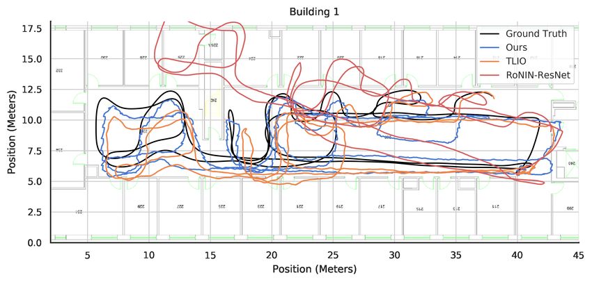
the accelerometer and magnetometer of the IMU by proxy           are then fed to a modality-specific Support Vector Regres-
of their measurements of gravitational acceleration and the      sor (SVR) to determine a correction applied before the ac-
Earth’s magnetic field. By looking at a small temporal win-      celeration is double-integrated to determine user position.
dow of IMU measurements, this module learns to estimate          Cortes, Solin, and Kannala (2018) use a convolutional neu-
a more accurate device orientation, and by extension, results    ral network (CNN) to regress momentary user speed as a
in a more accurate device location. We train a two-stage deep    constraint. The speed acts as a pseudo-measurement update
network to estimate the 5D device pose – 3D orientation and      to an EKF that performs accelerometer double-integration as
2D position (3D position is also possible).                      its process update.
   The contributions of our work are: (i) a state-of-the-art        IONet and the remaining work forgo dead-reckoning and
deep network architecture to perform inertial orientation es-    instead rely on deep networks to bypass one set of integra-
timation, which we show leads to improved position esti-         tion, thereby limiting error growth. In IONet, a bi-directional
mates; (ii) an end-to-end model that produces more accu-         long-short-term memory (BiLSTM) network is given a win-
rate position estimation than previous classical and learning-   dow of world-frame accelerometer and gyroscope measure-
based techniques; and (iii) a building-scale inertial sensor     ments (with the reference frame conversion done by the
dataset of annotated 6D pose (3D position + orientation) dur-    phone API), from which it sequentially regresses a polar
ing human motion.                                                displacement vector describing the device’s motion in the
                                                                 ground plane. This single integration helps minimize the er-
                   2    Related Work                             ror magnification. The bulk of their work is evaluated in
We place inertial systems into two broad categories based on     a small Vicon motion capture studio with different motion
their approaches to localization and orientation: traditional    modalities, e.g., in the pocket.
methods and data-driven methods.                                    RoNIN builds on the IONet approach and presents three
                                                                 different neural network architectures to tackle inertial lo-
2.1   Traditional Localization Methods:                          calization: an LSTM network, a temporal convolutional net-
Dead reckoning with an IMU using the analytical solution         work (TCN), and a residual network (ResNet). These models
consists of integrating gyroscopic readings to determine sen-    regress user velocity/displacement estimates in the ground
sor orientation (e.g., Rodrigues’ rotation formula), using       (x-y) plane.
those orientations to rotate accelerometer readings into the        TLIO is a recent work that uses a ResNet-style architec-
global frame, removing gravitational acceleration, and then      ture from RoNIN to estimate positional displacements. They
double-integrating the corrected accelerometer readings to       fuse these deep estimates with the raw IMU measurements
determine position (Chen et al. 2018a). The multiple inte-       using a stochastic-cloning EKF, which estimates position,
grations lead to errors being magnified over time, resulting     orientation, and the sensor biases.
in an unusable estimate within seconds. However, additional         The present work suggests current data-driven inertial lo-
system constraints on sensor placement and movement can          calization approaches lack a robust device orientation esti-
be used to reduce the amount of drift, e.g., foot mounted        mator. Previous networks rely heavily on direct gyroscope
ZUPT inertial navigation systems that rely on the foot being     integration or the device’s estimate, which fuses accelerom-
stationary when in contact with the ground to reset errors       eter, gyro, and magnetometer readings using classical meth-
(Jimenez et al. 2009). Extended Kalman Filters (EKFs) are        ods. While these estimates may be accurate over the short
often used to combine IMU readings accurate in the near-         term, they are prone to discontinuities, unstable readings,
term with other localization methods that are more accurate      and drift over time. The success of data-driven approaches
over the long term, like GPS (Caron et al. 2006), cameras        in localization suggests similar possibilities for orientation
(Qin, Li, and Shen 2018), and heuristic constraints (Solin       estimation.
et al. 2018).

2.2   Data-driven Localization Methods:                          2.3   Traditional Orientation Estimation Methods:
Recent years have seen the development of new data-driven        Prior work for device orientation estimation are primarily
methods for inertial odometry. Earlier work vary from ap-        based on traditional filtering techniques. The Madgwick fil-
proaches like RIDI (Yan, Shan, and Furukawa 2018), which         ter (Madgwick, Harrison, and Vaidyanathan 2011) is used
relies on SVMs, to deep network approaches like Cortes,          widely in robotics. In the Madgwick filter, gyroscope read-
Solin, and Kannala (2018), IONet (Chen et al. 2018a),            ings are integrated over time to determine an orientation es-
RoNIN (Herath, Yan, and Furukawa 2020), and TLIO (Liu            timate. This is accurate in the short term but drifts due to
et al. 2020).                                                    gyroscope bias. To correct the bias, a minimization is per-
   RIDI and Cortes, Solin, and Kannala (2018) fundamen-          formed between two vectors: (1) the static world gravity
tally rely on dead-reckoning, i.e., double-integrating accel-    vector, rotated into the device frame using the current es-
eration, but differ in how they counteract the resulting ex-     timated orientation, and (2) the acceleration vector. The ma-
treme drift. RIDI uses a two-stage system to regress low-        jor component of the acceleration vector is assumed to be
frequency corrections to the acceleration. A Support Vector      gravity, so it calculates a gradient to bring the gravity vector
Machine (SVM) classifies the motion as one of four hold-         closer to the acceleration vector in the current frame. The
ing modalities (e.g. in the hand, the purse) from the ac-        orientation estimate consists of a weighted combination of
celerometer/gyroscope measurements. These measurements           this gradient and the gyroscope integration. This assumes the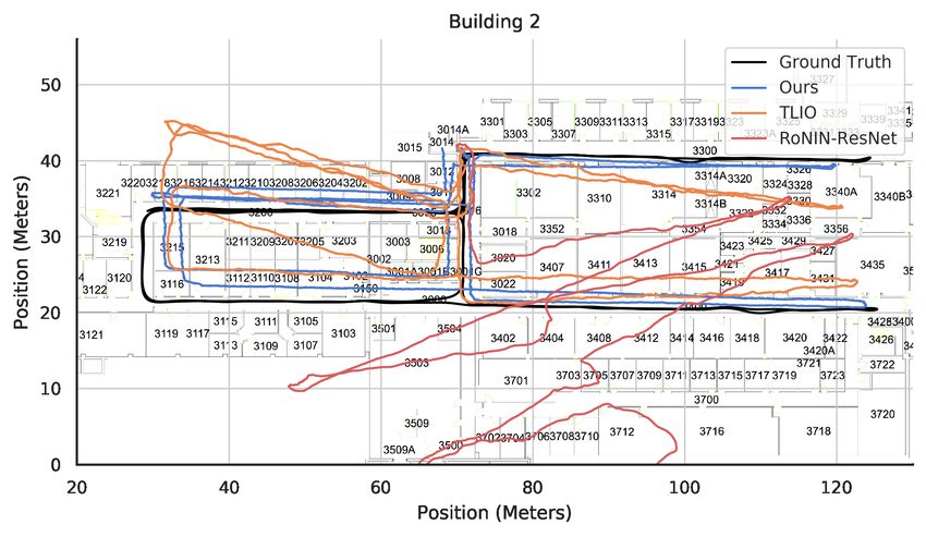
non-gravitational acceleration components are small, which       network with higher accuracy than that achievable with the
is impractical for pedestrian motion.                            heuristic-based traditional filtering methods.
   Complementary filters are also used in state-of-the-art
orientation estimation systems like MUSE (Shen, Gowda,           3.1   Estimating 3D Orientation:
and Roy Choudhury 2018). MUSE behaves similarly to the           We propose a network architecture for estimating device ori-
Madgwick filter, but uses the acceleration vector as the tar-    entation. The network consists of two components: (1) an
get of the orientation update only when the device is static.    orientation network that estimates a device orientation from
Instead, they mainly use the magnetic north vector as the        the provided acceleration, angular velocity, and magnetome-
basis of the gradient calculation. This has the advantage of     ter readings and (2) an Extended Kalman filter to further sta-
removing the issue of large non-gravitational accelerations      bilize the network output with the gyroscope readings. The
causing erroneous updates since when the device is static,       resulting 3D orientation is used to rotate the accelerometer
the acceleration vector consists mostly of gravity. However,     and gyroscope channels from the phone’s coordinate system
a static device is rare during pedestrian motion and magnetic    to a world coordinate system. The corrected measurements
fields can vary significantly from within the same building      are then passed as inputs to the position network.
due to local disturbances which are difficult to characterize.      We use a neural network, referred to as the Orientation
   Extended Kalman Filter (EKF) approaches (Bar-Itzhack          Network (OrientNet), to convert IMU measurements to a 3D
and Oshman 1985; Marins et al. 2002; Sabatini 2006) fol-         orientation and a corresponding covariance estimate. Instead
low a similar approach to the previously mentioned filters,      of directly converting the magnetic field or acceleration vec-
but use a more statistically rigorous method of combining        tor to orientation, as is done in traditional filtering methods,
gyroscope integration with accelerometer/magnetometer ob-        we use a neural network to learn a data-driven mapping of
servations. An estimate of the orientation error can also be     other sensor measurements to orientation. We find that the
extracted from this type of filter. We take advantage of such    magnetic field measurements contribute most reliably to this
a filter in our work, but replace the gravity vector or mag-     estimate (much more than gravity), in agreement with the
netic north measurement update with the output of a learned      claims by Shen, Gowda, and Roy Choudhury (2018).
model to provide a less noisy estimate of the true orientation      Formally, we estimated the instantaneous 3D orientation
and simplify the Kalman update equations.                                         θ̂, Σ̂ = g(at , ω t , Bt , h0t−1 ),       (1)
2.4   Data-driven Orientation Estimation Methods:                where the function g consists of a 2-layer LSTM with 100
                                                                 hidden units and h0t−1 is a hidden state produced by the
Recent literature like OriNet (Esfahani et al. 2020)             LSTM at the last time step. At each time step, the accelerom-
and Brossard, Bonnabel, and Barrau (2020) (abbreviated           eter, gyroscope, and magnetometer readings (a, ω, B) are
Brossard et. al. (2020)) has begun utilizing deep networks       taken as input. The hidden state is then fed through 2 fully-
to regress orientation from IMU measurements. OriNet uses        connected layers to produce an absolute orientation θ̂ in the
a recurrent neural architecture based on LSTMs to propagate      global reference frame, and through two other fully con-
state. It corrects for gyroscopic bias via a genetic algorithm
                                                                 nected layers to produce an orientation covariance Σ̂. This
and sensor noise via additive Gaussian noise during training.
                                                                 covariance represents the auto-covariance of the 3-dim ori-
Brossard et. al. (2020) estimates orientation via gyroscopic
                                                                 entation error, determined using a boxminus operation be-
integration, but uses a CNN to perform a correction to the
                                                                 tween the true and estimated orientations (as defined in
angular velocity to filter out unwanted noise and bias prior
                                                                 equation 3), and is thus a 3×3 matrix. In the position esti-
to integration. These methods have primarily focused on fil-
                                                                 mation network described later, this orientation estimate will
tering gyroscopic data using deep networks and estimating
                                                                 be used as a coordinate transform to rotate the IMU channels
correction factors to reduce bias and noise. Our method di-
                                                                 from the local phone frame to the global reference frame.
rectly estimates an orientation from all IMU channels using
                                                                    We find that the OrientNet maintains high accuracy in
a deep network to capture all error sources for long-term ac-
                                                                 its orientation estimate over long periods of time, but does
curacy while fusing gyro data in the short term via an EKF.
                                                                 not achieve the fine-grain accuracy of gyroscope integration.
The prior data-driven approaches thus far have yet to include
                                                                 Using the raw gyroscope measurements as a process update
magnetic observations, which leaves performance on the ta-
                                                                 and the outputs of the orientation estimation network as a
ble given the success of incorporating magnetic observations
                                                                 measurement update in an Extended Kalman Filter (EKF),
in classical approaches.
                                                                 we can achieve higher local and global accuracy. We find the
                                                                 EKF outperforms deep networks at performing this fusion as
                       3    Method                               it handles the angular data with well-defined quaternion op-
We aim to develop a method for 3D orientation and 2D po-         erations while allowing for stable and intuitive fusion of our
sition estimation of a smartphone IMU held by a pedestrian       OrientNet outputs. We use a quaternion EKF (Bar-Itzhack
through the use of supervised learning. Our model is de-         and Oshman 1985) with process updates defined by
signed based on the knowledge that the accelerometer con-                        x̂k|k−1 = x̂k−1|k−1 + Bk ω k ,
tains information about the gravitational acceleration of the                                                               (2)
Earth and that the magnetometer contains information about                       P̂k|k−1 = P̂k−1|k−1 + Qk ,
the Earth’s magnetic field. Thus, it should be possible to in-   where the quaternion state x̂k−1|k−1 is the a posteriori esti-
fer the absolute 3D orientation of the device using a deep       mate of of the state at k − 1 given observations up to k − 1,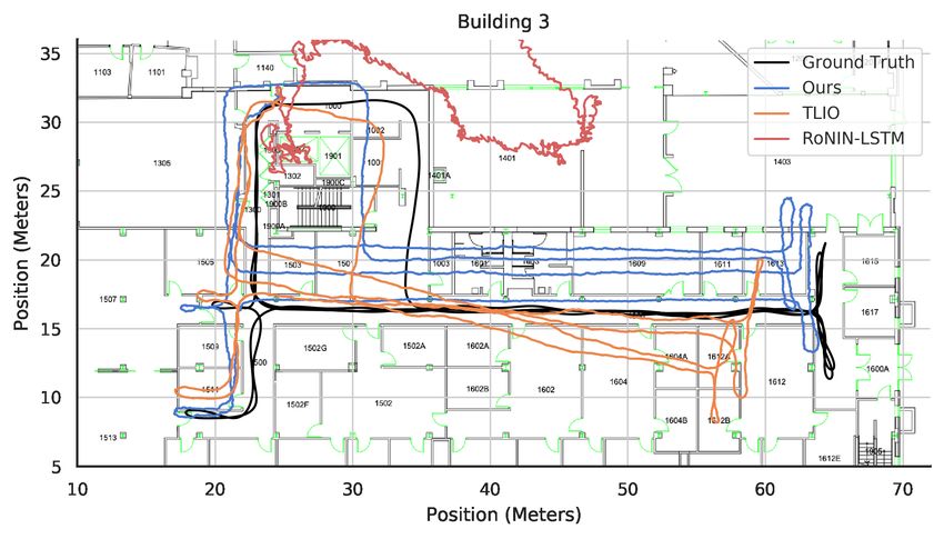
NLL Loss q x MSE Loss
a′1, ω′1 a′2, ω′2 Orientation Position xt − x1 x̂t − x̂1
Reference Reference Ground Truth
a1, ω1 Frame a2, ω2 Frame
᠁
Transform Transform
q̂ 1[4] q̂ 2[4]
x̂1 x̂2 x̂t x̂t+1 x̂t+2 x̂2t
Acc.
Extended Extended
ω1 ω2 0
Gyro Kalman Kalman ᠁ Initial Offset Initial Offset
Filter Filter
Linear Linear Linear Linear Linear Linear
Mag.
q1̂ , Σ̂ 1 q2̂ , Σ̂ 2
⊕ ⊕ ᠁ ⊕ ⊕ ⊕ ᠁ ⊕ ᠁
FC FC
h′
LSTM LSTM ᠁ FC FC FC FC FC FC
OrientNet
BiLSTM BiLSTM ᠁ BiLSTM BiLSTM BiLSTM ᠁ BiLSTM
a1, ω1, B1 a2, ω2, B2
a′1, ω′1 a′2, ω′2 a′t, ω′t a′t+1, ω′t+1 a′t+2, ω′t+2 a′2t, ω′2t
Orientation Module Position Module
Figure 2: Detailed system diagram. IMU readings are first passed to the orientation module, which is trained to estimate the
orientation quaternion q. This orientation is used to convert accelerometer/gyroscope readings from device to world frame.
These readings are passed to the position module, which is trained to minimize displacement error per window, for localization.
and x̂k|k−1 is the propagated orientation estimate at timestep displacement is encoded in δ. With these operators, the mea-
k given observations up to k − 1. The motion model is pa- surement update for our method becomes
rameterized by Bk , which converts the current gyroscope Kk = Pk|k−1 (Pk|k−1 + Rk )−1 ,
measurement ω k into a quaternion representing the rotation
achieved by ω k . The process update is applied via simple x̂k|k = x̂k|k−1 Kk (qk x̂k|k−1 ), (4)
addition, which approximates quaternion rotations at high Pk|k = (I − Kk )Pk|k−1 ,
sample rates. P̂k|k−1 is the estimate of the covariance of the where qk and Rk are the network-predicted orientation and
propagated state vector at time k given observations up to covariance for timestep k. The result of the measurement
k − 1, with P̂k−1|k−1 again the a posteriori estimate of co- update is the final orientation estimate for timestep k (x̂k|k )
variance at time k − 1. Qk is a static diagonal propagation and the estimated state covariance Pk|k .
noise matrix for the gyro, which we set to 0.005I3 based on
experimentation with our training data. 3.2 Orientation Module Training:
The EKF’s measurement updates correct the propagated To train the orientation module, we first perform a tradi-
state with the network-predicted orientation. Using normal tional ellipsoid fit calibration on the raw magnetometer val-
addition and subtraction as orientation operators becomes ues, which also serves to scale the network inputs to a con-
inaccurate since there is no guarantee the predicted and fined range (Kok and Schön 2016). From here on, we will
propagated quaternions lie close together. Thus, here we refer to these coarsely calibrated magnetometer readings as
treat the difference between orientations as a distance on the part of the raw IMU measurements. To obtain the mean and
quaternion manifold instead of as a vector-space distance us- covariance needed to parameterize a Gaussian estimate, a
ing the methods presented by Hertzberg et al. (2013). Box- negative log likelihood (NLL) loss is used to train the covari-
plus () and boxminus ( ), which respect the manifold, re- ance estimator for each orientation output. This loss seeks to
place addition and subtraction of quaternions: maximize the probability of the given ground truth, assum-
¯ −1 ⊗ q1 ) = δ, ing a Gaussian distribution parameterized by the estimated
q1 q2 = 2log(q 2 orientation and covariance:
q1 δ = q1 ⊗ exp(δ/2) = q2 , 1 −1 1
Lorient = (q q̂)T Σ̂ (q q̂) + ln(|Σ̂|). (5)
2 2
cos(kδk)
exp(δ) = , (3) The output of the covariance estimation head of the network
sinc(kδk)δ
( is a six dimensional vector, following a standard parame-
¯ w 0, v=0 terization of a covariance matrix (Russell and Reale 2019).
log( ) = atan(kvk/w) . The first three elements are the log of the standard devia-
v kvk v, v 6= 0
tion, which are then exponentiated and squared to form the
q1 and q2 are unit quaternions; δ is the three-dimensional diagonal elements of the covariance matrix. The remaining
manifold difference between them. w and v are the real and 3 are correlation coefficients between variables, which are
imaginary parts of a quaternion, respectively. These oper- multiplied by the relevant exponentiated standard deviations
ators maintain the unit norm and validity of the resulting to form the covariance elements of the matrix.
quaternions. The norm of δ between two quaternions de-
scribes the distance along a unit sphere between the orien- 3.3 Estimating 2D Position:
tations. Adding δ to a quaternion using results in another Analytically, to convert from the world frame accelerometer
valid quaternion displaced from the initial quaternion. This values to position, one would need to perform two integrals.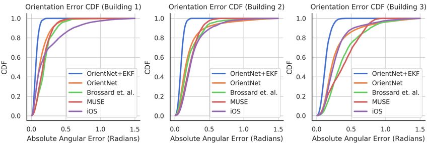
However, any offsets in the acceleration values would result
in quadratic error growth. Therefore, we again adopt the use
of a neural network to learn an appropriate approximation
that is less susceptible to error accumulation, as has been
demonstrated successfully by Herath, Yan, and Furukawa
(2020) and Chen et al. (2018a). The position estimation net-
work takes world frame gyroscope and accelerometer chan-
nels as inputs and outputs the final user position in the same
global reference frame as the orientation module. We use a
                                                                       Figure 3: Data collection SLAM rig (Kaarta Stencil)
Cartesian parameterization of the user position to match that
of the rotated accelerometer.
   The position module’s architecture is depicted in Figure 2.
We primarily rely on a 2-layer BiLSTM with a hidden size            builds were instructed to walk with variable speeds, pauses,
of 100. The input is a sequence of 6-DOF IMU measure-               and arbitrary directional changes while carrying the map-
ments in the world frame. At each timestep, the hidden state        ping rig and smartphone. Participants were allowed to hold
is passed to 2 fully-connected layers with tanh activation          the rig however they wished (e.g., 90 degrees offset) and to
between them and hidden state sizes of 50 and 20, respec-           readjust their grip as needed, so trajectories include varia-
tively. The resulting vector is then passed to a linear layer       tions in rig orientation relative to the user. An initial magne-
that converts it to a two-dimensional Cartesian displacement        tometer calibration (Kok and Schön 2016) was performed at
relative to the start of each window. These are then summed         the start location.
over time to form Cartesian positions relative to the start of         Since the user must carry the mapping system to which
the sequence, with each window’s final position serving as          the phone is mounted, the user’s motions are somewhat un-
the initial offset for the next window. During test time, the       natural. However, we argue that the major factors that com-
LSTM hidden states are not propagated between each se-              plicate inertial pedestrian localization are maintained, such
quence window, as this periodic resetting helps to limit the        as the lack of both zero-velocity points and movement con-
accumulation of drift.                                              straints on any axis of the device. Subjects were allowed
                                                                    to shake and orient the rig relative to their walking direc-
3.4   Position Module Training:                                     tion however they liked. Furthermore, RoNIN and IONet
Over the course of training, progressively longer batch se-         have already demonstrated that deep networks can general-
quences are provided. We start with sequences of length 100         ize across different ways of holding a phone and to differ-
and progressively increase this over training to length 2000.       ent brands of smartphones. Because testing such modalities
We find this type of curriculum learning greatly reduces drift      makes it much more difficult to acquire ground truth device
accumulation as the overall error must be kept low over a           orientation (such as in-the-pocket), we primarily rely on the
longer time period. After this routine, the sequence length         induced motion over the course of normal movement to gen-
may then be dropped back down to a shorter length to re-            erate realistic device motions. While RoNIN and IONet pro-
duce latency. We use MSE loss over the displacement of              vide two of the largest datasets for pedestrian inertial odom-
each LSTM window. In other words,                                   etry, they lack the necessary data channels for our model.
                                                                    IONet’s dataset, OxIOD (Chen et al. 2018b), lacks raw IMU
            Lposition = LMSE (xt − x1 , x̂t − x̂1 ) .        (6)    values without the iOS CoreMotion processing and coor-
                                                                    dinate transform already applied, so our orientation mod-
                        4    Dataset                                ule is unable to be used. Furthermore, their ground truth
To collect trajectories through the narrow hallways of a typ-       orientations display consistent artifacts at certain orienta-
ical building, we rely on a SLAM rig (Kaarta Stencil) as            tions, which would corrupt a supervised model trained on
ground truth. To obtain the phone’s ground truth orientation        them. RoNIN does not provide ground truth phone orienta-
and position, we rigidly mount it to the rig, which uses a Li-      tions, instead opting to provide the orientation of a second
DAR sensor, video camera, and Xsens IMU to estimate its             Google Tango phone attached to the user’s body; this means
pose at 200Hz. From testing in a Vicon motion capture stu-          we cannot train our orientation module on their trajectories.
dio, we measured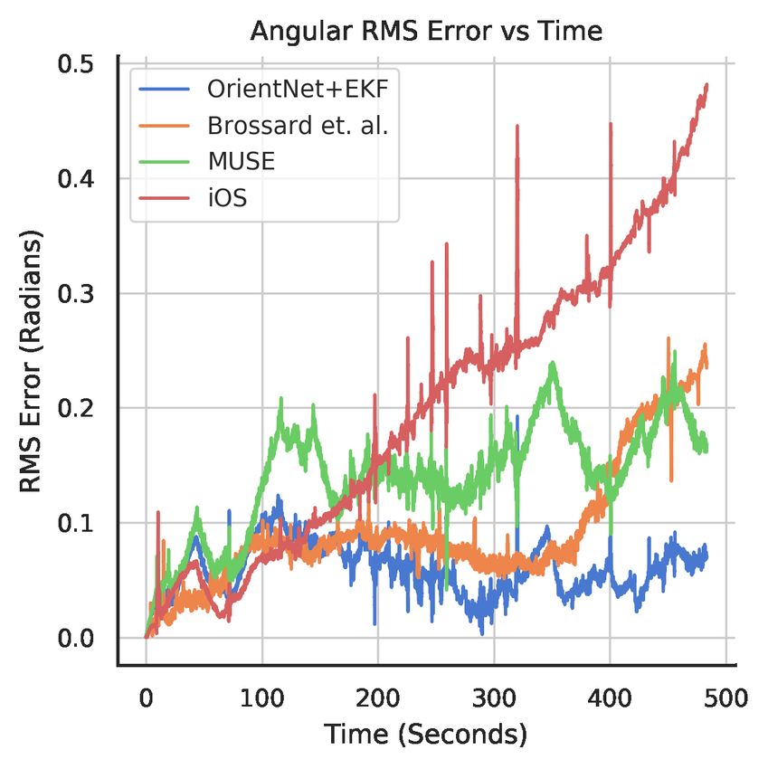
5    Experiments                                     System                    Bldg 1   Bldg 2   Bldg 3
To demonstrate the effectiveness and utility of our inertial              iOS CoreMotion              0.39     0.37     0.40
odometry system, we set three main goals for evaluation: (i)              MUSE                        0.21     0.25     0.45
verify that our model produces better orientation estimates               Brossard et. al. (2020)     0.23     0.30     0.47
than the baselines, (ii) show that our model is able to achieve           OrientNet only (ours)       0.21     0.44     0.49
higher position localization accuracy than previous methods,              OrientNet+EKF (ours)        0.08     0.10     0.14
and (iii) demonstrate that orientation error is a major source
of final position error by showing that other inertial odome-       Table 1: Orientation RMSE comparison (in radians). Each
try methods benefit from our orientation module.                    building is separately trained and tested; building test sets
   The main metric used to evaluate the orientation mod-            are of similar length (∼2.5 hr each).
ule is root mean squared (RMSE) orientation error, mea-
sured as the direct angular distance between the estimated
and ground truth orientations. We evaluate the accuracy of          IMU, it must have limited computational demands. Using
our position estimate using metrics defined by Sturm et al.         only an AMD Ryzen Threadripper 1920x CPU, the forward
(2011) and used by RoNIN:                                           inference time is approx. 65ms for 1s of data (100 samples),
• Absolute Trajectory Error (ATE): the RMSE between                 which suggests real-time capabilities on mobile processors.
  corresponding points in the estimated and ground truth
  trajectories. The error is defined as Ei = xi − x̂i where         5.2   Baselines:
  i corresponds to the timestep. This is a measure of global
  consistency and usually increases with trajectory length.         To evaluate our orientation module, we compare it against
• Time-Normalized Relative Traj. Error (T-RTE): the                 the iOS CoreMotion API, Brossard et. al. (2020), and MUSE
  RMSE between the displacements over all corresponding             (Shen, Gowda, and Roy Choudhury 2018). The CoreMotion
  1-minute windows in the estimated and ground truth tra-           estimate is selected for its ubiquity; Brossard et. al. (2020)
  jectories. The error is defined as Ei = (xi+t − xi ) −            is the most competitive deep learning estimator since they
  (x̂i+t − x̂i ) where i is the timestep and t is the interval.     outperform OriNet; MUSE is a high-performance traditional
  This measures local consistency between trajectories.             approach. As a reminder, CoreMotion and MUSE fuse mag-
                                                                    netic readings.
• Distance-Normalized Relative Traj. Error (D-RTE):
  the RMSE between the displacements over all corre-                   To show the performance of our inertial odometry
  sponding windows in the estimated and ground truth tra-           pipeline, we compare it against several different baseline
  jectories where the ground truth trajectory has traveled          inertial odometry methods. Pedestrian Dead Reckoning is
  1 meter. The error is defined as Ei = (xi+td − xi ) −             chosen as the representative of traditional odometry meth-
  (x̂i+td − x̂i ) where i corresponds to the timestep and td        ods. We use a similar PDR baseline to (Herath, Yan, and
  is the interval length required to traverse a distance of 1m.     Furukawa 2020) that involves regressing a heading and dis-
                                                                    tance every physical step. We assume a stride length of
The RMSE for these metrics is calculated using the follow-          0.67m/step and use the heading from iOS CoreMotion.
ing equation where Ei is the i-th error term out of m total:           The main data-driven inertial localization methods ex-
                           v                                        plored in prior work are IONet, RoNIN, and TLIO, all of
                           u      m
                           u1 X                                     which take orientation estimates directly from the phone
              RM SE = t              kEi k22 .          (7)         API. For IONet, we use our own implementation as the orig-
                              m i=1
                                                                    inal code is not publicly available. IONet was primarily eval-
                                                                    uated in a small Vicon motion capture room. We have found,
5.1   Training/Testing:                                             however, that IONet does not perform very well in large
We implemented our model in Pytorch 1.15 (Paszke et al.             indoor environments, which is consistent with experiments
2019) and train it using the Adam optimizer (Kingma and             run by Herath, Yan, and Furukawa (2020). We evaluate all 3
Ba 2015) on an Nvidia RTX 2080Ti GPU. The orienta-                  RoNIN variants–LSTM, TCN, and ResNet–using their exact
tion network is first individually trained using a fixed seed       open source implementation. In our evaluations using their
and a learning rate of 0.0005. Then, using these initialized        code, we noticed a bug in their evaluation metric, where they
weights, the position network is attached and then trained          omitted the L2-norm in their calculation of RMSE when de-
using a learning rate of 0.001. We use a batch size of 64,          riving ATE and RTE (see Equation 7). Because of this error,
with the network reaching convergence within 20 epochs.             their metrics consistently under-report the true error; how-
Each epoch involves a full pass through all training data.          ever, the relative comparisons between their models and the
   At test time, an initial orientation can be provided or, as-     conclusions are still valid because this is applied consis-
suming a calibrated magnetometer, the initial orientation can       tently. We use the correct method for these metrics, which
be estimated by the network directly with high accuracy rel-        explains the discrepancies between the relative sizes of our
ative to a predefined global frame. This cannot be said for         errors (in addition to trajectories being from different build-
systems that rely solely on gyroscope integration, which pro-       ings and of different lengths). TLIO uses RoNIN-ResNet
duces an orientation relative to the initialization. As this sys-   with stochastic-cloning EKF to refine the orientation esti-
tem is meant to aid pedestrian navigation using a smartphone        mates; we use their released code for evaluation.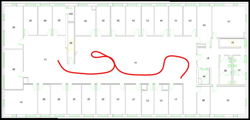
Bldg 1, Known Subjects                Bldg 1, Unknown Subjects
                                                                      Model
                                                                                         ATE        T-RTE        D-RTE         ATE        T-RTE         D-RTE

                                                                      PDR               26.98        16.49          2.26       24.29       12.65            2.77
                                                                      IONet             33.42        22.97          2.47       31.28       24.04            2.29
                                                                      RoNIN-LSTM        18.62         7.02          0.53       18.17        6.51            0.51
                                                                      RoNIN-TCN         12.00         6.41          0.48       13.41        5.82            0.48
                                                                      RoNIN-ResNet       9.03         6.43          0.56       12.07        5.95            0.49
                                                                      TLIO               4.62         2.52          0.31        6.34        4.22            0.46
Figure 4: Comparison of model CDFs for orientation error              Ours               4.39         2.14          0.30        5.65        2.61            0.38

                                                                     Table 2: Model position generalization across subjects.
                                                                     Known subjects (2.4hr) present in train split; unknown
                                                                     (2.2hr) were not.

                                                                                     Building 1                  Building 2                    Building 3
                                                                     Model
                                                                                ATE T-RTE D-RTE ATE T-RTE D-RTE ATE T-RTE D-RTE

                                                                     PDR        25.70 14.66       2.50   21.86    19.48       1.66     12.66    12.74       1.09
                                                                     R-LSTM     18.41 6.78        0.52   29.81    18.67       0.75     33.69    13.14       0.62
                                                                     R-TCN      12.67 6.13        0.48   22.52    13.69       0.73     24.79    12.48       0.59
                                                                     R-ResNet   10.48 6.20        0.53   35.44    15.71       0.49     14.11    11.78       0.60
 (a) Model error between true (b) Correlation between orien-         TLIO        5.44 3.33        0.38    8.69     8.86       0.33     6.88     6.68        0.34
 and predicted orientations.  tation error & covariance esti-        Ours        4.99 2.37        0.34   8.33      5.97       0.41     6.62     2.86        0.26
                              mate of predicted error dist.
                                                                     Table 3: Comparison across buildings using separately-
         Figure 5: Orientation module performance
                                                                     trained models. RoNIN models abbreviated with ”R-”.

5.3   Orientation Analysis:                                          mate can sometimes recover from such drastic error growth
We now seek to answer the question of whether our orien-             eventually via magnetic observations, our pipeline quickly
tation pipeline is worth using, i.e., does it outperform the         and frequently adapts to keep the orientation estimate accu-
systems that others use? We perform evaluations on our               rate in the face of constant device motion. Figure 5b shows
building-scale dataset, where each trajectory occurs over a          the predicted standard deviation correlates well with the ac-
long time period of 10 minutes that allows one to more eas-          tual error. The square root of the trace of the predicted orien-
ily discern accumulated drift. Table 1 demonstrates that our         tation covariance matrix is, due to the manifold structure of
model outperforms competing approaches by a considerable             our loss, the standard deviation of the absolute angular error.
margin when trained separately on trajectories from each             Overall, 60% our estimates lie within one predicted standard
building. Averaging across all three buildings, our estimate         deviation (a new covariance is predicted for each timestep)
is 0.28 radians (16.04◦ ) more accurate than CoreMotion’s            of the true orientation, 90% lie within 2 standard deviations,
estimate, 0.22 radians (12.83◦ ) more accurate than Brossard         and 97% lie within 3. This approximately matches with the
et. al. (2020), and 0.20 radians (11.50◦ ) more accurate than        expected probabilities of a Gaussian distribution, which sug-
MUSE’s. While MUSE and Brossard et. al. (2020) outper-               gests our network is producing reasonable covariance esti-
form the base OrientNet slightly, the OrientNet+EKF main-            mates.
tains a significant lead. In fact, at 0.08 radians (4.6◦ ) in Bldg
1, our method nearly reaches the ground truth rig’s accuracy.        5.4     Position Analysis:
   Figure 4’s comparison of the error CDFs is particularly           Tables 2 and 3 show the comparison between between our
useful in understanding relative performance. We can see             end-to-end model and a mix of traditional and deep-learning
that the EKF addresses one of the main limitations of us-            baselines. Table 2 demonstrates that a single model trained
ing only the OrientNet–namely that the outliers with high            on Building 1 generalizes well to both Known Subject and
errors are eliminated. While the base OrientNet performs             Unknown Subjects test sets; furthermore, it outperforms all
better than the other approaches most of the time, it has a          other methods on both sets. TLIO is closest in performance
larger proportion of large error terms due to jitter and oc-         because their EKF helps reduce drift by estimating sensor
casional discontinuities that appear in the output, which re-        biases. One point to note is the consistent performance of
duces RMSE down to the level of the others. Our full orien-          PDR in the ATE metric. It is capable of achieving (rela-
tation module significantly outperforms other methods in all         tively) low errors for this metric because of the fewer up-
metrics with better performance and fewer outliers.                  dates which take place as a result of step counting, so the
   The error growth over time is evident in Figure 5a, where         overall trajectory tends to stay in the same general region.
all other methods exhibit a steeper error growth than ours–          Some of the other models tend to drift slowly over time un-
which stays relatively flat. While MUSE and the iOS esti-            til the trajectory is no longer centered in the same original
Method Metric R-LSTM R-TCN R-ResNet TLIO
ATE 18.41 12.67 10.48 5.44
API
Orientation T-RTE 6.78 6.13 6.20 3.33
D-RTE 0.52 0.48 0.53 0.38
ATE 7.03 6.04 5.66 4.67
Our
Orientation T-RTE 2.71 2.56 2.63 2.39
D-RTE 0.35 0.30 0.39 0.29
ATE 6.53 5.69 4.49 4.53
True
Orientation T-RTE 2.33 2.17 2.17 2.30
D-RTE 0.28 0.26 0.38 0.27
Table 4: Localization using different orientation estimates
on Building 1. RoNIN models abbreviated with ”R-”.
location despite almost always producing more accurate tra-
jectory shapes, as reflected by the lower RTE metrics. IONet
does not perform well on these large buildings, so will be
omitted for the remaining results.
Table 3 presents the results of separately training models
for evaluation per building. Here, our position estimate out-
performs all other methods, especially in RTE. Lower RTE
means the trajectory shape is more similar to ground truth
while lower ATE means the position has generally deviated
less. Note that Bldg 2 and 3 result in larger errors due to their
size and the increased presence of magnetic distortions that
degrade orientation estimates reliant on magnetic readings.
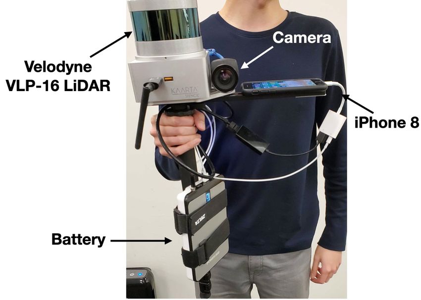
Figure 6 compares some example trajectories in all three Figure 6: Trajectory comparison among our’s, TLIO, and
buildings among our method, the best performing variant of RoNIN. Same initial pose and truncated slightly for clarity.
RoNIN, and TLIO. This succinctly illustrates the importance
of a good orientation estimator, as TLIO and RoNIN’s use
of the phone estimate results in rotational drift that compro- ations, as long as our model is trained on a building with
mises the resulting position estimate (to the extent that the magnetic distortions, it can produce accurate orientation es-
trajectories can leave the floorplan entirely). timates that far exceed existing methods. This is due to its
Table 4 examines the impact on position error from using ability to capture magnetic field variation, but comes at the
the phone orientation, our orientation, and the ground truth cost of degraded generalization in novel environments.
orientation on TLIO and RoNIN. We can see that not only
does our orientation module improve the performance of all 6 Conclusion
other position models (quite significantly for RoNIN), but In this work, we present a novel data-driven model that
it also nearly reaches the theoretical maximum performance is one of the first to integrate deep orientation estimation
where ground truth orientations are directly provided. with deep inertial odometry. Our orientation module uses an
LSTM and EKF to form a stable, accurate orientation esti-
5.5 Generalization mate that outperforms traditional and data-driven techniques
In our experiments, we notice two distinct failure modes for like CoreMotion, MUSE, and Brossard et. al. (2020). Com-
model generalization to new environments. The first is ori- bined with a position module, this end-to-end-system local-
entation failure due to reliance on magnetic readings, which izes better than previous methods across multiple buildings
leads to degraded performance in environments with wildly and users. In addition, our orientation module is a swap-in
different magnetic fields from training, e.g., in new build- component capable of empowering existing systems with
ings. The second is position failure due to variations in build- orientation performance comparable to visual-inertial sys-
ing shape/size. Buildings in our dataset vary in dimension tems in known environments. Lastly, we build a large dataset
from tens to hundreds of meters and in composition of sharp of device pose, spanning 20 hours of pedestrian motion
vs rounded turns. While the first mode affects our model due across 3 buildings and 15 people. Existing traditional inertial
to reliance on magnetic data, we discovered that all data- odometry methods either use assumptions or constraints on
driven methods suffer from the second failure mode, regress- the user’s motion, while previous data-driven techniques use
ing position inaccurately in cross-building evaluations (train classical orientation estimates. A pertinent issue future work
on one location, test on held-out location). This is perhaps should address is generalization across buildings through
unsurprising, as data-driven methods are known to fail on further data collection in unique environments, data aug-
out-of-distribution examples. Regarding magnetic field vari- mentation, or architectural modifications.References j.inffus.2011.08.003. URL https://doi.org/10.1016/j.inffus.
Ahmetovic, D.; Gleason, C.; Ruan, C.; Kitani, K.; Takagi, 2011.08.003.
H.; and Asakawa, C. 2016. NavCog: A Navigational Cogni- Jimenez, A. R.; Seco, F.; Prieto, C.; and Guevara, J. 2009. A
tive Assistant for the Blind. Proceedings of the 18th Inter- comparison of Pedestrian Dead-Reckoning algorithms using
national Conference on Human-Computer Interaction with a low-cost MEMS IMU. 2009 IEEE International Sympo-
Mobile Devices and Services 90–99. doi:10.1145/2935334. sium on Intelligent Signal Processing 37–42. ISSN null. doi:
2935361. URL https://doi.org/10.1145/2935334.2935361. 10.1109/WISP.2009.5286542.
Bar-Itzhack, I.; and Oshman, Y. 1985. Attitude Determi- Kingma, D. P.; and Ba, J. 2015. Adam: A Method for
nation from Vector Observations: Quaternion Estimation. Stochastic Optimization. 3rd International Conference for
Aerospace and Electronic Systems, IEEE Transactions on Learning Representations, San Diego URL http://arxiv.org/
Vol. AES-21: 128 – 136. doi:10.1109/TAES.1985.310546. abs/1412.6980.
Brossard, M.; Bonnabel, S.; and Barrau, A. 2020. Denois- Kok, M.; and Schön, T. B. 2016. Magnetometer calibration
ing IMU Gyroscopes With Deep Learning for Open-Loop using inertial sensors. CoRR abs/1601.05257. URL http:
Attitude Estimation. IEEE Robotics and Automation Letters //arxiv.org/abs/1601.05257.
5(3): 4796–4803. doi:10.1109/LRA.2020.3003256. Liu, W.; Caruso, D.; Ilg, E.; Dong, J.; Mourikis, A.; Dani-
Burri, M.; Nikolic, J.; Gohl, P.; Schneider, T.; Rehder, J.; ilidis, K.; Kumar, V.; Engel, J.; Valada, A.; and Asfour,
Omari, S.; Achtelik, M. W.; and Siegwart, R. 2016. The Eu- T. 2020. TLIO: Tight Learned Inertial Odometry. IEEE
RoC micro aerial vehicle datasets. The International Journal Robotics and Automation Letters 1–1. ISSN 2377-3774. doi:
of Robotics Research 35(10): 1157–1163. 10.1109/lra.2020.3007421. URL http://dx.doi.org/10.1109/
LRA.2020.3007421.
Caron, F.; Duflos, E.; Pomorski, D.; and Vanheeghe, P. 2006.
GPS/IMU Data Fusion Using Multisensor Kalman Filter- Madgwick, S.; Harrison, A.; and Vaidyanathan, R. 2011. Es-
ing: Introduction of Contextual Aspects. Inf. Fusion 7(2): timation of IMU and MARG orientation using a gradient
221–230. ISSN 1566-2535. doi:10.1016/j.inffus.2004.07. descent algorithm. IEEE International Conference on Re-
002. URL https://doi.org/10.1016/j.inffus.2004.07.002. habilitation Robotics 2011: 1–7. doi:10.1109/ICORR.2011.
5975346.
Chen, C.; Lu, X.; Markham, A.; and Trigoni, N. 2018a.
IONet: Learning to cure the curse of drift in inertial odom- Marins, J.; Yun, X.; Bachmann, E.; Mcghee, R.; and Zyda,
etry. Thirty-Second AAAI Conference on Artificial Intelli- M. 2002. An Extended Kalman Filter for Quaternion-Based
gence . Orientation Estimation Using MARG Sensors. IEEE Inter-
national Conference on Intelligent Robots and Systems 4.
Chen, C.; Zhao, P.; Lu, C. X.; Wang, W.; Markham, A.; and doi:10.1109/IROS.2001.976367.
Trigoni, N. 2018b. OxIOD: The Dataset for Deep Inertial
Odometry. CoRR abs/1809.07491. URL http://arxiv.org/abs/ Paszke, A.; Gross, S.; Massa, F.; Lerer, A.; Bradbury, J.;
1809.07491. Chanan, G.; Killeen, T.; Lin, Z.; Gimelshein, N.; Antiga, L.;
Desmaison, A.; Kopf, A.; Yang, E.; DeVito, Z.; Raison, M.;
Cortes, S.; Solin, A.; and Kannala, J. 2018. Deep Learning Tejani, A.; Chilamkurthy, S.; Steiner, B.; Fang, L.; Bai, J.;
Based Speed Estimation for Constraining Strapdown Iner- and Chintala, S. 2019. PyTorch: An Imperative Style, High-
tial Navigation on Smartphones. 2018 IEEE 28th Interna- Performance Deep Learning Library. Advances in Neural
tional Workshop on Machine Learning for Signal Processing Information Processing Systems 32 8024–8035. URL
(MLSP) 1–6. doi:10.1109/MLSP.2018.8516710. http://papers.neurips.cc/paper/9015-pytorch-an-imperative-
Cortés, S.; Solin, A.; Rahtu, E.; and Kannala, J. 2018. AD- style-high-performance-deep-learning-library.pdf.
VIO: An authentic dataset for visual-inertial odometry. Pro- Qin, T.; Li, P.; and Shen, S. 2018. VINS-Mono: A Ro-
ceedings of the European Conference on Computer Vision bust and Versatile Monocular Visual-Inertial State Estima-
(ECCV) 419–434. tor. IEEE Transactions on Robotics 34(4): 1004–1020. ISSN
Esfahani, M. A.; Wang, H.; Wu, K.; and Yuan, S. 2020. 1941-0468. doi:10.1109/TRO.2018.2853729.
OriNet: Robust 3-D Orientation Estimation With a Single Russell, R. L.; and Reale, C. 2019. Multivariate Uncertainty
Particular IMU. IEEE Robotics and Automation Letters in Deep Learning. arXiv e-prints arXiv:1910.14215.
5(2): 399–406. doi:10.1109/LRA.2019.2959507.
Sabatini, A. M. 2006. Quaternion-based extended Kalman
Herath, S.; Yan, H.; and Furukawa, Y. 2020. RoNIN: Robust filter for determining orientation by inertial and magnetic
Neural Inertial Navigation in the Wild: Benchmark, Eval- sensing. IEEE Trans. Biomed. Engineering 53(7): 1346–
uations, New Methods. 2020 IEEE International Confer- 1356. URL http://dblp.uni-trier.de/db/journals/tbe/tbe53.
ence on Robotics and Automation (ICRA) 3146–3152. doi: html#Sabatini06.
10.1109/ICRA40945.2020.9196860. Schubert, D.; Goll, T.; Demmel, N.; Usenko, V.; Stückler,
Hertzberg, C.; Wagner, R.; Frese, U.; and SchröDer, L. 2013. J.; and Cremers, D. 2018. The TUM VI benchmark for
Integrating Generic Sensor Fusion Algorithms with Sound evaluating visual-inertial odometry. IEEE/RSJ International
State Representations through Encapsulation of Manifolds. Conference on Intelligent Robots and Systems (IROS) 1680–
Inf. Fusion 14(1): 57–77. ISSN 1566-2535. doi:10.1016/ 1687.Shen, S.; Gowda, M.; and Roy Choudhury, R. 2018. Closing the Gaps in Inertial Motion Tracking. Proceedings of the 24th Annual International Conference on Mobile Computing and Networking 429–444. doi:10.1145/3241539.3241582. URL https://doi.org/10.1145/3241539.3241582. Solin, A.; Cortes Reina, S.; Rahtu, E.; and Kannala, J. 2018. Inertial Odometry on Handheld Smartphones. 2018 21st International Conference on Information Fusion (FUSION) 1361–1368. doi:10.23919/ICIF.2018.8455482. URL http: //urn.fi/URN:NBN:fi:aalto-201812106229. Sturm, J.; Magnenat, S.; Engelhard, N.; Pomerleau, F.; Co- las, F.; Burgard, W.; Cremers, D.; and Siegwart, R. 2011. Towards a benchmark for RGB-D SLAM evaluation. Proc. of the RGB-D Workshop on Advanced Reasoning with Depth Cameras at Robotics: Science and Systems Conf. (RSS) . Yan, H.; Shan, Q.; and Furukawa, Y. 2018. RIDI: Robust IMU Double Integration. Proceedings of the European Con- ference on Computer Vision (ECCV) . Zhang, J.; and Singh, S. 2014. LOAM: Lidar Odometry and Mapping in Real-time. Proceedings of Robotics: Science and Systems Conference .
You can also read