Electric Load Driven Longboard - JOHAN ANDERSSON RICKARD HÖGLUND - KTH ROYAL INSTITUTE OF TECHNOLOGY SCHOOL OF INDUSTRIAL ENGINEERING AND ...
←
→
Page content transcription
If your browser does not render page correctly, please read the page content below
DEGREE PROJECT IN TECHNOLOGY,
FIRST CYCLE, 15 CREDITS
STOCKHOLM, SWEDEN 2020

Electric Load Driven
Longboard
JOHAN ANDERSSON

RICKARD HÖGLUND

KTH ROYAL INSTITUTE OF TECHNOLOGY
SCHOOL OF INDUSTRIAL ENGINEERING AND MANAGEMENT
Electric Load Driven Longboard

        JOHAN ANDERSSON
        RICKARD HÖGLUND

       Bachelor’s Thesis at ITM
       Supervisor: Nihad Subasic
       Examiner: Nihad Subasic

        TRITA-ITM-EX 2020:29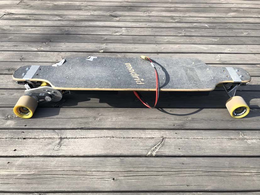
Abstract
Keywords: mechatronics, longboard, brushless direct cur-
rent motor, Hall effect sensor, load cell, Wheatstone bridge,
LiPo battery, Arduino, ODrive

This bachelor’s thesis aims to show an extensive overview
of all the parts that build up an electric load driven long-
board and see if a load controlled longboard can be seen as
a safe, comfortable and convenient alternative to the more
common remote controlled longboard. The thesis will also
answer how weight can be measured on a longboard in the
most effective way, what the most comfortable riding tech-
nique is and what a good motor-battery configuration to
be able to travel at 30 km/h and 10 km would be.

The longboard measures the weight distribution with load
cells located between the deck and the trucks. An Arduino
translates the input from the load cells to a certain speed
and then sends it to an ODrive which controls a BLDC mo-
tor that is powered by two LiPo batteries.

The results show that a load controlled longboard can very
well be seen as a good alternative if right riding technique
is used. The best technique is when the longboard acceler-
ates when the rider tilts and keeps a constant speed when
the rider stands straight. The best way to measure the
weight is to fasten the trucks with hinges which lets the
load cells register weight without anything interfering. Not
all tests could be done because of Covid-19 but a measured
top speed of 15 km/h with a high gear ratio is a promising
result for the future when more suitable gear ratios will be
tested to try to reach the goal of 30 km/h.
Referat
           Elektrisk lastdriven longboard
Nyckelord: mekatronik, longboard, borstlös likströmsmotor,
Hall effekt sensor, lastcell, Wheatstone brygga, LiPo batte-
ri, Arduino, ODrive

Det här kandidatexamensarbetet strävar efter att visa en
omfattande överblick på alla delar som bygger upp en elekt-
risk lastdriven longboard och se om en laststyrd longboard
kan ses som ett säkert, komfortabelt och behändigt alterna-
tiv till den vanligare radiostyrda longboarden via handkon-
troll. Det här arbetet kommer också svara på hur vikt kan
mätas på en longboard på ett så effektivt sätt som möjligt,
vad som är den mest bekväma åkstilen och vad är en bra
motor-batteri konfiguration för att kunna åka i 30 km/h
och nå 10 km skulle vara.

Longboarden mäter viktfördelningen med lastceller som är
placerade mellan brädan och truckarna. En Arduino om-
vandlar indatan från lastcellerna till en specifik hastighet
som den sedan skickar till en ODrive som kontrollerar en
borstlös likströmsmotor som i sin tur är driven av två LiPo
batterier.

Resultaten visar att en laststyrd longboard kan mycket väl
ses som ett bra alternativ om rätt åkstil används. Den
bästa stilen är att longboarden accelererar när åkaren lu-
tar sig och håller en konstant hastighet när åkaren står
rakt. Det bästa sättet att mäta vikt är att montera truc-
karna på gångjärn som låter lastcellerna mäta vikt utan
att något stör. Alla tester kunde inte utföras på grund av
Covid-19 men en uppmätt topphastighet på 15 km/h med
en hög utväxling är ett lovande resultat för framtiden när
lämpligare utväxlingar kommer testas för att försöka nå
målet på 30 km/h.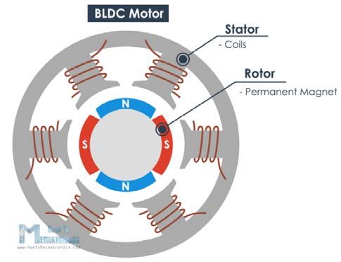
Acknowledgements

We would like to thank our supervisor Nihad Subasic for his feedback through-
out this project and making sure it could all continue despite the situation that
was present during this project. We also wish to show gratitude to Seshagopalan
Thorapalli Muralidharan for being a huge help when the project became very chal-
lenging. He came up with helpful ideas and helped us getting parts manufactured
that was needed for the longboard. We would also like to thank Staffan Qvarnström
for ordering parts and teaching us how to solder.
Contents

1 Introduction                                                                                                                                       1
  1.1 Background     .   .   .   .   .   .   .   .   .   .   .   .   .   .   .   .   .   .   .   .   .   .   .   .   .   .   .   .   .   .   .   .   1
  1.2 Purpose . .    .   .   .   .   .   .   .   .   .   .   .   .   .   .   .   .   .   .   .   .   .   .   .   .   .   .   .   .   .   .   .   .   1
  1.3 Scope . . .    .   .   .   .   .   .   .   .   .   .   .   .   .   .   .   .   .   .   .   .   .   .   .   .   .   .   .   .   .   .   .   .   2
  1.4 Method . .     .   .   .   .   .   .   .   .   .   .   .   .   .   .   .   .   .   .   .   .   .   .   .   .   .   .   .   .   .   .   .   .   2

2 Theory                                                                                                                                             3
  2.1 Deck . . . . . . . . . . .                 .   .   .   .   .   .   .   .   .   .   .   .   .   .   .   .   .   .   .   .   .   .   .   .   .   3
  2.2 Trucks and Wheels . . .                    .   .   .   .   .   .   .   .   .   .   .   .   .   .   .   .   .   .   .   .   .   .   .   .   .   3
  2.3 Motor . . . . . . . . . .                  .   .   .   .   .   .   .   .   .   .   .   .   .   .   .   .   .   .   .   .   .   .   .   .   .   3
  2.4 Hall effect sensor . . . .                 .   .   .   .   .   .   .   .   .   .   .   .   .   .   .   .   .   .   .   .   .   .   .   .   .   5
  2.5 Battery . . . . . . . . .                  .   .   .   .   .   .   .   .   .   .   .   .   .   .   .   .   .   .   .   .   .   .   .   .   .   6
  2.6 Powertrain . . . . . . .                   .   .   .   .   .   .   .   .   .   .   .   .   .   .   .   .   .   .   .   .   .   .   .   .   .   7
  2.7 Load Cells . . . . . . . .                 .   .   .   .   .   .   .   .   .   .   .   .   .   .   .   .   .   .   .   .   .   .   .   .   .   7
  2.8 Control Unit . . . . . .                   .   .   .   .   .   .   .   .   .   .   .   .   .   .   .   .   .   .   .   .   .   .   .   .   .   8
      2.8.1 Microcontroller .                    .   .   .   .   .   .   .   .   .   .   .   .   .   .   .   .   .   .   .   .   .   .   .   .   .   8
      2.8.2 Motor controller                     .   .   .   .   .   .   .   .   .   .   .   .   .   .   .   .   .   .   .   .   .   .   .   .   .   9

3 Demonstrator                                                                                                                                       10
  3.1 Powertrain . . . . . . . . . . .                           .   .   .   .   .   .   .   .   .   .   .   .   .   .   .   .   .   .   .   .   .   10
      3.1.1 Motor . . . . . . . . . .                            .   .   .   .   .   .   .   .   .   .   .   .   .   .   .   .   .   .   .   .   .   10
      3.1.2 Battery . . . . . . . . .                            .   .   .   .   .   .   .   .   .   .   .   .   .   .   .   .   .   .   .   .   .   10
      3.1.3 Gear Ratio and Wheels                                .   .   .   .   .   .   .   .   .   .   .   .   .   .   .   .   .   .   .   .   .   12
      3.1.4 ODrive . . . . . . . . .                             .   .   .   .   .   .   .   .   .   .   .   .   .   .   .   .   .   .   .   .   .   13
      3.1.5 Arduino Uno . . . . . .                              .   .   .   .   .   .   .   .   .   .   .   .   .   .   .   .   .   .   .   .   .   13
      3.1.6 Programming . . . . . .                              .   .   .   .   .   .   .   .   .   .   .   .   .   .   .   .   .   .   .   .   .   13
      3.1.7 Gears and Timing Belt                                .   .   .   .   .   .   .   .   .   .   .   .   .   .   .   .   .   .   .   .   .   16
  3.2 Load Cells . . . . . . . . . . . .                         .   .   .   .   .   .   .   .   .   .   .   .   .   .   .   .   .   .   .   .   .   17
  3.3 Design . . . . . . . . . . . . . .                         .   .   .   .   .   .   .   .   .   .   .   .   .   .   .   .   .   .   .   .   .   18
      3.3.1 Layout . . . . . . . . . .                           .   .   .   .   .   .   .   .   .   .   .   .   .   .   .   .   .   .   .   .   .   18
      3.3.2 Load Cell Mounting . .                               .   .   .   .   .   .   .   .   .   .   .   .   .   .   .   .   .   .   .   .   .   18
      3.3.3 Motor Mount . . . . . .                              .   .   .   .   .   .   .   .   .   .   .   .   .   .   .   .   .   .   .   .   .   21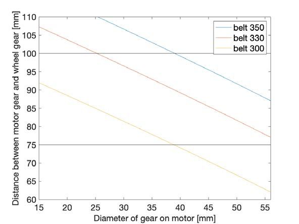
4 Results                                                                                                          22
  4.1 Load cell placement and weight       distribution    .   .   .   .   .   .   .   .   .   .   .   .   .   .   22
  4.2 Riding Technique . . . . . . . .     . . . . . . .   .   .   .   .   .   .   .   .   .   .   .   .   .   .   22
  4.3 Top Speed . . . . . . . . . . . .    . . . . . . .   .   .   .   .   .   .   .   .   .   .   .   .   .   .   23
  4.4 Distance . . . . . . . . . . . . .   . . . . . . .   .   .   .   .   .   .   .   .   .   .   .   .   .   .   23

5 Discussion and Conclusion                                                                                        24
  5.1 Discussion . . . . . . . . . . . . . . . . . . . . . . . . . . . . . . . . .                                 24
  5.2 Conclusion . . . . . . . . . . . . . . . . . . . . . . . . . . . . . . . .                                   26

6 Recommendations and Future Work                                                                                  27

Bibliography                                                                                                       28

Appendices                                                                                                         30

A Configuration for the ODrive                                                                                     32
  A.1 Motor configuration . . . . . . . . . . . . . . . . . . . . . . . . . . .                                    32
  A.2 Encoder configuration . . . . . . . . . . . . . . . . . . . . . . . . . .                                    33

B Code for the Arduino                                                                                             34
  B.1 Prototype and definitions header file . . . . . . . . . . . . . . . . . .                                    34
  B.2 Code where both HX711 are used . . . . . . . . . . . . . . . . . . . .                                       35
  B.3 Code where only one HX711 is used . . . . . . . . . . . . . . . . . .                                        42

C MATLAB code                                                                                                      49

D Pictures of the final product                                                                                    54
List of Figures
2.1 Parts of the BLDC motor [4]. . . . . . . . . . . . . . . . . . . . . . . . . 4
2.2 Motor used to drive the longboard [5]. . . . . . . . . . . . . . . . . . . . 5
2.3 Hall effect principle with no magnetic field in the left image and with a
magnetic field present in the right image [7]. . . . . . . . . . . . . . . . . 6
2.4 The powertrain setup used on the longboard. Made with Microsoft Pow-
erpoint. . . . . . . . . . . . . . . . . . . . . . . . . . . . . . . . . . . . . 7
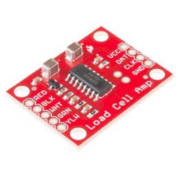
2.5 Load cell amplifier used to connect the load cells with the Arduino [12]. 8
2.6 Load cell used to measure the weight distribution [13]. . . . . . . . . . . 8
2.7 The ODrive used to control the motor [17]. . . . . . . . . . . . . . . . . 9
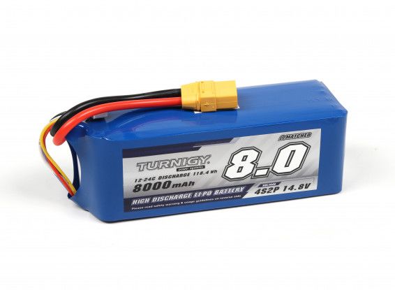
3.1 Battery used to power the longboard [20]. . . . . . . . . . . . . . . . . . 12
3.2 A flowchart of the code. The velocity is measured in Hall effect sensor
counts per second. Made with draw.io . . . . . . . . . . . . . . . . . . . 15
3.3 Calculated needed distance between the gears. Made with MATLAB. . 16
3.4 300 mm belt [21] used and the ring fitted between the wheel and gear.
Made with Solid Edge. . . . . . . . . . . . . . . . . . . . . . . . . . . . . 16
3.5 Wheatstone bridge configuration with two load cells. Made with Mi-
crosoft Powerpoint. . . . . . . . . . . . . . . . . . . . . . . . . . . . . . . 17
3.6 The two cases for the batteries, ODrive and Arduino. Made with Solid
Edge. . . . . . . . . . . . . . . . . . . . . . . . . . . . . . . . . . . . . . 18
3.7 Load cell placement of mount type 1, (dimensions not to scale). Made
with Microsoft Powerpoint. . . . . . . . . . . . . . . . . . . . . . . . . . 19
3.8 Deflection of metal plate under the load cells. Made with MATLAB. . . 19
3.9 Mounting type 1 and mounting type 2. Made with Solid Edge. . . . . . 20
3.10 Mounting type 3. The hinges are placed on the near side of the load cell
mount. Made with Solid Edge. . . . . . . . . . . . . . . . . . . . . . . . 20
3.11 The motor mount. Made with Solid Edge. . . . . . . . . . . . . . . . . . 21
A.1 The configuration of the motor in ODrive tool. . . . . . . . . . . . . . . 32
A.2 The configuration of the Hall sensor in ODrive tool. . . . . . . . . . . . 33
D.1 The finished longboard . . . . . . . . . . . . . . . . . . . . . . . . . . . . 54
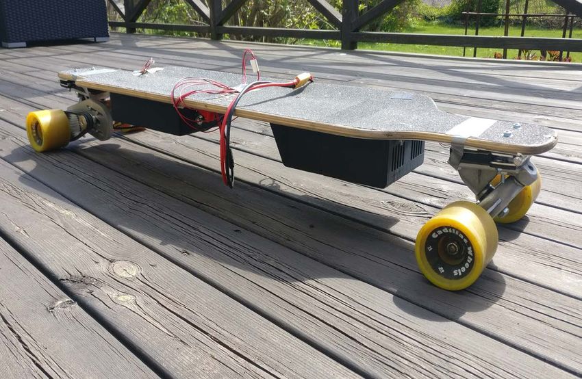
D.2 Close up of the powertrain and the load cell mount with its load cells . 55
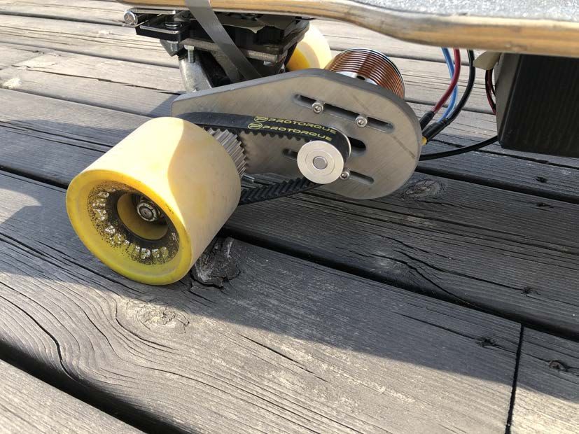
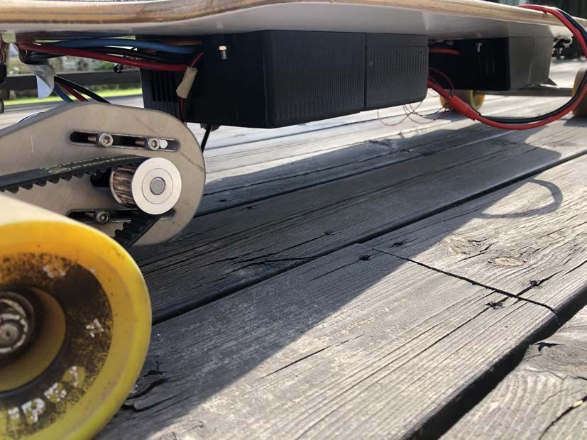
D.3 The underside of the longboard . . . . . . . . . . . . . . . . . . . . . . . 56List of Tables 2.1 Motor specifications . . . . . . . . . . . . . . . . . . . . . . . . . . . . . 5 2.2 Load cell specifications . . . . . . . . . . . . . . . . . . . . . . . . . . . . 8 3.1 Possible battery configurations . . . . . . . . . . . . . . . . . . . . . . . 11
List of Abbreviations

BLDC - Brushless direct current
CPR - Counts per revolution
CPU - Central processing unit
GPIO - General-purpose input/output
I/O - Input/output
Li-ion - Litium ion
LiPo - Lithium polymer
MCU - Microcontroller unit
mAh - Milliampere hour
PLA - Polylactide
RPM - Revolutions per minute
UART - Universal asynchronous receiver-transmitter
Chapter 1

Introduction

1.1    Background
A longboard is a type of skateboard. Due to its characteristics such as the length
and the bigger and softer wheels it rolls a lot better and smoother and is therefore
more often used for commuting and downhill riding. A longboard does require a
bit of work from the user since the user have to kick to propel it forward. This can
get quite exhausting after a while.

Electric longboards already exists on the market. These make it possible to travel
without having to kick but the rider has to use a remote controller to pilot it
instead. The downsides of this is that the user can lose the controller, it can run
out of battery and it can lose connection to the board. To be able to travel on a
longboard without having to propel it by kicking or without having to use a remote
controller presented itself as an interesting challenge, thus this project was chosen.

1.2    Purpose
The purpose of this thesis is to examine how a load driven electrical longboard
should be set up so a person can ride it comfortably and safe. The thesis strive to
answer the following questions:

  • What is a good motor-battery configuration to have a top speed of 30 km/h
    and a range of 10 km?

  • What is a good way to consistently measure weight on a longboard?

  • How does a person control the longboard in the most comfortable way?

  • Can a load controlled longboard be seen as a safe, comfortable and convenient
    alternative to a remote controlled longboard?

                                          1
CHAPTER 1. INTRODUCTION
1.3 Scope
During this project there are time and resource limitations. The course runs
throughout the spring term of 2020. Because of this a regular longboard should
be purchased second hand and modified to make it electric and load driven.
Electrical vehicles such as longboards are defined by The Swedish Transport Agency
as bicycles [1]. This means they are not allowed to be driven at speeds exceeding
20 km/h. Since the longboard developed in this project has a goal of cruising at 30
km/h, it will only be used at gated and private areas. Hence this project should also
not aim to comply with some of the other laws such as needing headlights, safety
reflectors and a bell.
1.4 Method
In order to answer the research questions a regular longboard was purchased second
hand. The rest of the components for the project were gathered after research and
calculations were done to decide upon what was needed. In the ensuing part of
the project designing and constructing took place. The manufactured parts were
mostly done by 3D-printing, but also by waterjet cutting.
As the construction was completed and all the functions and features that the board
was supposed to have was decided upon, the code was written. It was iterated and
updated to include new features several times and was made sure to include safety
measures before the board was tested outside with the motor connected to the
wheel. When this was completed the different riding techniques, weight measuring
components, top speed, and distance could be tested.
2Chapter 2
Theory
2.1 Deck
The deck is the part of the longboard where you stand. It is most often made out
of wood in several layers. A deck is categorized by its flex which describes how
flexible the deck is and how much it bends when you stand on it. The higher the
flex the more flexible it is. In this project a lower flex would be preferred to be able
to mount the batteries, Arduino Uno and ODrive as good as possible underneath
the deck. If the deck flexes too much the cases containing the sensitive components
may break due to unexpected loads or due to the fact that they might touch or be
dragged along the pavement. The deck can come in many different shapes. This
deck will be symmetrical which makes it easy to ride in both directions.
2.2 Trucks and Wheels
To be able to corner and change direction with the longboard special wheel mounts
are needed which are called trucks. The trucks translate a leaning motion of the
rider to a turning motion of the front and rear axles, thus changing the direction
of the board. On this longboard the trucks are 180 mm wide. These also work as
mounting point for the motor mount. The wheel type is determined by its diameter
and hardness. The wheels for a longboard are generally around 70 mm in diameter,
and have a hardness of 80 out of a scale between 75 and 100 where 100 is the hardest.
2.3 Motor
The motor on a longboard needs to be light and strong so a brushless motor is
preferred. This is because brushless direct current (BLDC) motors do not use
brushes for commutation, instead this is done electronically [2]. Avoiding using
brushes means that there is no mechanical contact between the commutator and
said brushes, thus the operating life is drastically increased and the BLDC can put
3CHAPTER 2. THEORY
out a lot of power and torque relative to its size [3]. The BLDC motor works in
such a way that a current is applied to the coils on the stator seen in Fig. 2.1.
Figure 2.1: Parts of the BLDC motor [4].
The coils are energized in pairs to increase efficiency. When energized, they both
attract and repel the different poles on the rotor, which makes the rotor spin. To be
able to know when and in what sequence to energize these coils, the motor controller
will read a sensor [2].
When it comes to deciding which BLDC to use, one will have to check the specifi-
cations for the motor. The most important specifications for hobby BLDC motors
are described in the equation:
rpm = KV · V, (2.1)
where the KV value describes the linear relation between input voltage and the
revolutions per minute (rpm) of the motor. Most motors used to propel longboards
generally have a KV rating of slightly under 200 KV. The motor chosen for this
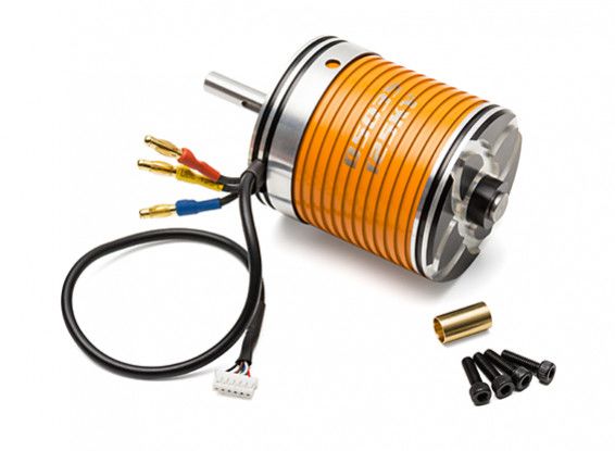
project is a Turnigy D5035-125KV Sensored Brushless Motor [5] and can be seen in
Fig. 2.2. The specifications are in Table 2.1. The efficiency of this motor is around
70% which means that the output rpm is 70% of what is calculated. It also has a
KV value of 125 KV which generally means that it is more suitable for situations
that needs more torque than top speed.
42.4. HALL EFFECT SENSOR
Figure 2.2: Motor used to drive the longboard [5].
Table 2.1: Motor specifications
Model Turnigy D5035-125KV Sensored Brushless Motor
KV rating 125
Torque constant, KT 0.5 Nm/A
Max power 2000 W
Efficiency ≈ 70%
Max current 45 A
Shaft 8 mm
Weight 745 g
2.4 Hall effect sensor
As the chosen motor comes with a Hall effect sensor, it makes sense to use this
instead of a separate encoder which also can be used. Hall effect sensors work by
having a continuous current flow through the Hall element conductor and sensing
nearby magnetic fields [6]. When a magnetic field comes close to the sensor a voltage
will be generated that is perpendicular to both the current and the field [7]. This
is visualised in Fig. 2.3.
5CHAPTER 2. THEORY
Figure 2.3: Hall effect principle with no magnetic field in the left image and with
a magnetic field present in the right image [7].
This magnetic field will be created by the energizing of the windings and a voltage
will therefore be generated and read by the sensor as the rotor of the BLDC spins
[2], [8]. This means that since the position of the rotors are known thanks to the
sensors, it is now also known which winding to energize.
2.5 Battery
When deciding upon batteries for a hobby BLDC motor the essential stats comes
down to voltage V, battery capacity or electric charge Q, and the continuous dis-
charge rate called C rating. Most batteries consists of cells rated to 3.7 V that are
connected in series and parallel to get a specific output. Batteries are often named
with a S and P value which describes this. When fully charged the cells are 4.2
V and when used they should not surpass 3.5 V to reduce the risk of permanent
damage. How many S a battery has describes how many cells are connected in
series. The higher the S value, the more volts you can get from the battery. The
P value characterize how many cells are connected in parallel and the higher the P
value, the longer the battery will last before it is empty and the higher the electric
charge is. The voltage needed is calculated from equation (2.1) and the required
battery capacity in the unit mAh can be calculated by
E
Q= , (2.2)
V · 3.6
where the energy E is
E = F · s, (2.3)
where F is the resulting force and s is the wanted distance.
To propel an electric longboard a lot of electric power is needed which means that the
batteries required are very powerful and thereby sometimes dangerous to experiment
with. For electric longboards most batteries used are either lithium polymer (LiPo)
or lithium-ion (Li-ion) [9]. Li-ion are generally safer but more expensive than LiPo
batteries. The batteries used in this thesis are LiPo mostly because of the limited
budget. Some thought and care need to go into it when handling LiPo batteries.
62.6. POWERTRAIN
One of those things is that a balance charger is needed when charging to prevent
overcharging which can cause fires. Charging batteries that are hot to the touch or
visibly damaged is ill-advised and exposure to extreme temperatures is discouraged.
2.6 Powertrain
When it comes to propelling an electric longboard there are two established meth-
ods. The first is to have a motor inside the wheel, a so called hub motor [10].
Due to availability of a separate BLDC motor, the second option is chosen which
is to have the motor mounted to the rear truck and connected to one of the wheels
with a belt as seen in Fig. 2.4. A positive thing about this option is that the gear
ratio between the motor and the wheel can be chosen to best suit the top speed
and acceleration goals. The drivetrain consists of three parts; two gears and a belt.
The motor mount sits on one side of the truck and holds the motor. The motor is
mounted on the motor mount with four screws in two slots which allows the belt
tension to be changed. To prevent slip the belt is put around two pulleys, one on
the motor shaft and the other connected to the wheel.
Figure 2.4: The powertrain setup used on the longboard. Made with Microsoft
Powerpoint.
2.7 Load Cells
Compared to the electric longboards on the market today this longboard is con-
trolled by the rider’s weight distribution instead of a hand held speed controller. To
measure the weight distribution four load cells need to be installed on the longboard
between the trucks and the deck. To be able to handle the total weight of the rider
two load cells need to be mounted on each truck. A load cell like the one pictured
in Fig. 2.6, also known as a single strain gauge, consists of two resistors where one
of them may change resistance when the load cell is exposed to external forces. The
specifications for the load cell used in this thesis can be found in Table 2.2.
7CHAPTER 2. THEORY
Table 2.2: Load cell specifications
maximum measurable weight 50 kg
maximum allowed weight 75 kg
height 8.7 mm
length 33.8 mm
width 33.8 mm
With a maximum measurable weight of 50 kg per load cell, each truck can measure
100 kg which is sufficient for the purpose of this thesis. From each load cell there
are three wires, a red (E+), a white (O+) and a black (E-) which are connected to
the three wires on the other load cell to form a Wheatstone bridge. This ensures
that the longboard can measure enough weight without the load cells breaking and
it also makes the measuring of the load more accurate [11]. These wires are then
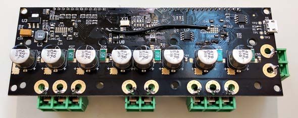
connected to the connectors on the load amplifier board, pictured in Fig. 2.5. The
load amplifier is then connected to the Arduino Uno via VCC, DAT, CLK and
GND.
Figure 2.5: Load cell amplifier used Figure 2.6: Load cell used to mea-
to connect the load cells with the Ar- sure the weight distribution [13].
duino [12].
2.8 Control Unit
2.8.1 Microcontroller
The microcontroller is used in this project to bridge the gap between the motor
controller and the load cells. A microcontroller unit (MCU) is a single-chip com-
puter system. There are a lot of different microcontrollers but what they all have
in common is that they consist of a central processing unit (CPU), some type of
memory and input/output ports (I/O) [14].
82.8. CONTROL UNIT
The Arduino Uno Rev3 is the MCU used in this project to enable the communication
between the load cells and the motor controller, in other words the communication
between the user and the BLDC motor. The Arduino Uno Rev3 is based on the
ATmega328P processor with 16MHz clock speed. It communicates using universal
asynchronous receiver-transmitter (UART). With 14 digital and 6 analog inputs
and outputs, together with 32 KB of flash memory, it will satisfy the needs for this
project [15].
2.8.2 Motor controller
A motor controller is needed to control the BLDC motor. In this case an ODrive
is used and can be seen in Fig. 2.7. ODrive is an open source motor controller
developed by Oskar Weigl from Sweden [16]. It is specifically designed to make it
possible to use inexpensive brushless motors in high performance robotics projects.
Normally an encoder is used alongside the ODrive for it to know the current position
of the motor, but a Hall effect sensor can be used as a substitute. The ODrive uses
the programming language Python and lets the user configure the motor. It also
has several interfaces that can be used to communicate with it from other devices,
one of which is UART that is conveniently also used by Arduino Uno.
Figure 2.7: The ODrive used to control the motor [17].
9Chapter 3
Demonstrator
There are two major goals set for the performance specifications of the electric
longboard:
• The top speed should be 30 km/h.
• The user should be able to travel at least 10 km on one full charge.
3.1 Powertrain
3.1.1 Motor
As the first performance goal with this longboard is to have a top speed of 30 km/h
the required voltage needed to get the correct rpm of the motor and the wheel which
has a diameter of 74 mm is calculated. The rotational speed of the wheel is
60 v 60 30
· = · 3.6
≈ 2150.7 rpm (3.1)
2π rwheel 2π 0.074
2
where v is the speed of the longboard and rwheel is the radius of the wheel. Together
with the KV value and efficiency of the motor the required input voltage can be
calculated. With a gear ratio of 1:1 the required voltage is
rpm 2150.7
ef f iciency
V = = 0.7
≈ 24.6 V. (3.2)
KV 125
3.1.2 Battery
The other performance goal with the longboard is to be able to go 10 km on one
charge. To know how much electric charge is needed the force and energy needs to
be calculated. The force is partly the rolling resistance force calculated as
Frr = Crr · N = Crr · m · g (3.3)
103.1. POWERTRAIN
where Crr is the rolling resistance coefficient between the wheel and the surface, m is
the mass of the longboard and rider collectively, and g is the gravitational constant.
The mass is set to 90 kg as a maximum value as that is seen as a reasonable number
for the user in mind with a good bit of margin to account for the weight of the
longboard. The exact value of the rolling resistance coefficient is unknown but 0.04
is a reasonable estimate as the wheels are polyurethane [18]. According to these
assumptions the rolling resistance force is
Frr = 0.04 · 90 · 9.81 ≈ 35.3 N. (3.4)
At top speed there will also be some drag that has to be taken into account. The
drag force is calculated with the following equation:
1
FD = · ρ · Cd · A · v 2 (3.5)
2
where Cd is the drag coefficient, A is the frontal area, and ρ is the density of the
air. With a frontal area of about 1 m2 , density of air equal to 1.27 kg/m2 and the
drag coefficient of 1.2 [19], the drag force is
1
FD = · 1.27 · 1.2 · 1 · 8.3332 ≈ 52.9 N (3.6)
2
which inserted in equation (2.3) together with the desired distance s = 10 km results
in the energy
E = (Frr + FD ) · s ≈ 882.3 kJ. (3.7)
To get the required capacity equation (2.2) is used:
E 882330
Q= = ≈ 9971.2 mAh. (3.8)
V · 3.6 24.6 · 3.6
These calculations indicates that the battery should have 25 V and about 10 Ah.
These calculations are based on the longboard constantly traveling at the top speed
of 30 km/h which is not required by the way the goal is set. This means that the
required capacity is a bit lower. It was decided that 8 Ah is enough based on the
over estimations and battery costs but such battery with the right voltage does not
exist. Thus a battery pack has to be created. With the stats needed for the battery
decided, the two options presented in Table 3.1 were considered after some research.
Table 3.1: Possible battery configurations
Type In series In parallel Total Total Cells Cost
voltage battery capacity
[pieces] [pieces] [V] [mAh] [pieces] [SEK]
LiP o 2 1 29.6 8000 8 1211
LiP o 7 4 25.9 8800 28 1919
11CHAPTER 3. DEMONSTRATOR
Since the performance of the configurations are very similar, the big factors consid-
ered for the choice was the work that would be required to put everything together
and the cost. With this in mind the first configuration with two batteries in series
and one in parallel was chosen. This is a Turnigy battery sold by company Hobbyk-
ing [20]. This battery pack has a voltage above the calculated one, which is good
since there will be some energy losses. This battery has a C rating of twelve, which
gives a safe continuous discharge rate of
8 Ah · 12C = 96 A (3.9)
and with a peak discharge rate of double that. The peak discharge rate is safe to
be held for ten seconds [20].
Figure 3.1: Battery used to power the longboard [20].
3.1.3 Gear Ratio and Wheels
With a specific input voltage calculated the desired voltage and top speed can still
be changed by changing the wheel diameter and gear ratio between the motor and
wheel. The most common wheel size is around 70 mm in diameter but they can be
much larger. The gear ratio may also differentiate. By increasing the gear ratio the
acceleration will increase and the top speed will decrease. The acceleration is given
by:
Mv Kt · I
m·a= = . (3.10)
rwheel rwheel
With a gear ration of 1:1 and maximum current of 45 A the theoretical acceleration
will be:
0.5 · 45
a= ≈ 6.8 m/s2 . (3.11)
90 · 0.037
Such an acceleration is far too much for a longboard, so the acceleration is set to
a more reasonable value in the code. In the experiment phase of the project three
different sizes of the gear on the motor will be tested to see the difference.
123.1. POWERTRAIN
3.1.4 ODrive
The main purpose of the ODrive is to control the electric motor. As it can work
together with an Arduino, and exists in 56 V version with a peak current of 120 A
per motor, it is well suited for this project. The batteries are directly connected
to the ODrive via XT90 connectors and the ODrive is connected to the motor via
three phase wires. The ODrive is also connected to the Arduino via three wires,
two from the digital pins on the Arduino to GPIO on the ODrive, and one between
GND on the Arduino and GND on the ODrive. To protect the ODrive the motor
controller is encased in a 3D printed case that has three fans attached to it to
prevent the ODrive from overheating. The ODrive may get very hot because of the
high current running through it. When the ODrive is connected to the motor and
batteries, the configurations could take place. This is done in two parts, one for the
motor and one for the Hall sensor. For the motor it was mostly setting parameters
that define the way it behaves. This includes, amongst other things, velocity limit,
current limit and tolerances. The full configuration can be seen in Appendix A.1.
For the Hall sensor the calibration included finding out the amount of pole pairs the
BLDC motor has. By applying a low current one could spin the motor and feel the
resistance when passing the poles. By this method the pairs were found out to be
seven. With this information the counts per revolution (CPR) which is the encoder
resolution could be set. The full encoder configuration can be seen in Appendix
A.2.
3.1.5 Arduino Uno
The main purpose of the Arduino is to translate inputs from both load cell amplifiers
to a signal fed to the ODrive that describes what speed the motor should be rotating
at. To be able to take inputs from the load cell amplifiers and give inputs to the
ODrive two special libraries need to be downloaded to the Arduino. In that way new
specific commands can be used to both take information from the amplifiers and
the ODrive but also send information to the ODrive. In this case the Arduino tells
the ODrive what speed the motor should be running in Hall effect sensor counts per
second. The Arduino is powered by a separate battery pack with six AA batteries
connected in series. The nine-volt battery pack is connected to the power port via
an aircraft inspired switch.
3.1.6 Programming
Two different types of riding techniques were tested. Fig. 3.2 shows a compre-
hensive overview of the first riding technique in a flowchart, which is the one that
seemed as most intuitive before the test rides. The basic idea is that the longboard
is controlled by tilting. The longboard accelerates in the direction the rider tilts or
keeps a constant speed if the rider stands straight except for when the speed is close
to zero, then it will accelerate either forwards or backwards to keep the velocity at
zero. This is done in order to make sure the longboard can stay still without having
13CHAPTER 3. DEMONSTRATOR
the user needing to continuously shift their weight, and therefore enables the user
to relax. This is a valuable feature when the user is at traffic lights where unwanted
movement might be devastating and when trying to stand still on a surface that is
not level. The code will constantly check if the load cells register enough weight
and if they do not the longboard will come to a full stop quickly without locking
the wheels to ensure the safety of the board, other pedestrians and property. The
voltage of the LiPo batteries is also constantly monitored. If the voltage gets close
to what is set as drained, the top speed will be reduced to notify the rider. When
it actually is empty the longboard will come to a stop and the Arduino is put to
sleep so no more riding can be done. The entire code can be found in Appendix B.2
together with a header file in Appendix B.1 used to clean up the main program.
The flowchart of the second riding technique is almost identical to the one cor-
responding to the first riding technique. The difference is that instead of a tilt
resulting in a constant acceleration, a tilt results in a specific set speed. Depending
on how much the rider tilts the speed changes to the speed equivalent of a specific
weight distribution. The more the rider tilts in one direction the faster the long-
board goes in that direction and if the rider is standing straight the velocity is set
to zero.
143.1. POWERTRAIN
Figure 3.2: A flowchart of the code. The velocity is measured in Hall effect sensor
counts per second. Made with draw.io
15CHAPTER 3. DEMONSTRATOR
3.1.7 Gears and Timing Belt
The gear mounted on the wheel is a HTD 5M gear with 36 teeth and has a diameter
of 56 mm. The 5M means that the pitch, or the distance between each tooth, is 5
mm. The side of the gear is cone shaped but to be able to fit it to the wheel that
has a flat side, a 3D printed ring, as seen in Fig. 3.4 is placed between them. The
HTD 5M gears mounted on the motor have three different sizes. The smallest has
15 teeth and is 20 mm in diameter, the largest has the same size as the one mounted
on the wheel and the third gear has teeth and a diameter somewhere between the
smallest and largest. The motor mount is designed to have a distance between the
gears equal to 75-100 mm which is enough with three different sized HTD 5M belts
with lengths 300 mm, 330 mm and 350 mm. This is shown below in Fig. 3.3. The
calculations where made with MATLAB and the code can be found in Appendix C.
Figure 3.3: Calculated needed distance between the gears. Made with MATLAB.
Figure 3.4: 300 mm belt [21] used and the ring fitted between the wheel and gear.
Made with Solid Edge.
163.2. LOAD CELLS
3.2 Load Cells
The pair of load cells on each truck is connected as a Wheatstone bridge which is
shown below in Fig. 3.5.
Figure 3.5: Wheatstone bridge configuration with two load cells. Made with
Microsoft Powerpoint.
The Wheatestone Bridge is then connected to the load cell amplifier which is con-
nected to the Arduino via GND, 5V, AREF, and two digital pins. The Arduino is
in other words connected to two amplifiers each giving its own weight input.
17CHAPTER 3. DEMONSTRATOR
3.3 Design
The longboard weighs 7.6 kg, is 99 cm long and 27.5 cm wide. Pictures of the
completed longboard can be seen in Appendix D.
3.3.1 Layout
The batteries and the control unit are placed as close as possible to the trucks
where the deck is least bent. Everything except the load cells will be encased in two
separate cases, as seen in Fig. 3.6, to protect them from gravel, stone chips, water
or other materials or liquids that may cause damage. The batteries are placed in
the case shown to the left which sits behind the truck in the front. The other case
encloses the ODrive, the Arduino, the battery pack for the Ardunio and the load
cell amplifiers. That case is placed in the rear as close to the motor as possible
where the airflow is cleaner [22]. The case is placed there because the ODrive runs
the largest risk of overheating and therefore needs as much airflow through the case
as possible. As seen in Fig. 3.6, the case enclosing the ODrive has an air intake that
is placed on the side the ODrive lies, supplying fresh air that runs directly over the
fans that cools the ODrive. Each case is 3D printed with polylactide (PLA) plastic
as two separate pieces and are then glued together with superglue. The cases are
mounted to the deck with M4 screws.
Figure 3.6: The two cases for the batteries, ODrive and Arduino. Made with Solid
Edge.
3.3.2 Load Cell Mounting
As it was difficult to be sure how the designs of the load cell mounting would work in
actuality, three different versions were created that was thought to work, although
some were believed to work better than the others. What can be called load cell
mounting type 1 were designed so that the load cells are placed on a metal plate
that is wider than the truck as the load cells would not fit otherwise. To measure
the weight distribution the load cells are placed between the trucks and the deck as
seen in Fig. 3.7.
183.3. DESIGN
Figure 3.7: Load cell placement of mount type 1, (dimensions not to scale). Made
with Microsoft Powerpoint.
To make sure the longboard remain stable the load cells are mounted next to an
equally thick but bigger foam plate. To make the load cells take up most of the
load they are placed on the inside of the trucks. The load cells sit on a thin metal
plate that needs to be just thick enough to not bend. If it bends the load cells will
not work properly. To calculate the bending of the metal plate a formula from solid
mechanics from KTH is used [23]. Elementary case 3 gives the deflection:
Ql3 4
δ(ξ) = (ξ − 4ξ − 3) (3.12)
24EI
Where Q [N] is the force, E [N/m2 ] the elastic modulus, I [m4 ] the second moment
of area, l [m] the length of the plate and ξ the position where zero is at the end. A
metal plate with a thickness of 4 mm gives a deflection of just over one tenth of a
millimeter which is acceptable, see Fig 3.8.
Figure 3.8: Deflection of metal plate under the load cells. Made with MATLAB.
19CHAPTER 3. DEMONSTRATOR
Another way to mount the load cells is to place them directly above the trucks
between them and the deck. This one is referred to as type 2. A CAD-drawing of
both mounting types can be seen in Fig. 3.9.
Figure 3.9: Mounting type 1 and mounting type 2. Made with Solid Edge.
A third way to mount the load cells is to mount the trucks to the deck with hinges.
In that way the trucks are securely fastened in most directions on the outer edge
of the truck but allows rotation. By placing the load cells on the other side of the
truck towards the middle between the truck and the deck it is made sure that the
load cells will take up all the weight placed upon the board. This makes sure that
no weight is taken up by something else than the load cells which could otherwise
happen when the mount and deck is screwed together like on type 1 and type 2.
Load cell mounting type 3 can be seen in Fig. 3.10. All three mounting types will be
tested and the one that yields the best results, in other words, the one that makes
the load cells measure the weight distribution most accurately, is used in the final
product.
Figure 3.10: Mounting type 3. The hinges are placed on the near side of the load
cell mount. Made with Solid Edge.
203.3. DESIGN
3.3.3 Motor Mount
The motor mount is manufactured by waterjet cutting. The idea was to use stainless
steel, but as the two possible options were regular steel and aluminium the decision
fell upon aluminium. This was due to the fact that aluminium is more resistant to
rust than regular steel which is an important aspect to consider since the longboard
might run through water if it starts raining while out. Aluminium is also a lot lighter
which is preferred because a heavy longboard is difficult to carry, and takes more
power to propel. The downside of choosing aluminium is that it gets scratched and
damaged aesthetically more easily, but as aesthetics is a lower priority than function
for this project this did not matter. The motor mount part can be seen in Fig. 3.11.
The mount is clamped to the rear truck with an M5 screw. The hole opposite to the
screw head is threaded, so there’s no need to use a nut to get the clamping effect
desired. The BLDC motor is attached to the motor mount on the right side in the
elongated holes which makes it possible to vary the distance between the rear axle
and the motor shaft. The shortest distance is 7 cm and the longest is 11 cm which
is a larger span than calculated but is needed so the belt may be tightened properly.
Figure 3.11: The motor mount. Made with Solid Edge.
21Chapter 4
Results
4.1 Load cell placement and weight distribution
All load cell mounting types were tested with 3D printed mounts. Load cell mount
type 1 did not work at all. The load cells registered 0 kg. Load cell mount type
2 worked fairly well. They could to some extent measure the weight distribution
but the trucks had to be mounted very loose for the load cells to work. Load cell
mount type 3 worked satisfactorily. They could measure the weight distribution far
better than the other two types. However when the rider picked up the longboard
the trucks rotated freely and partially damaged the thin wires connected to the load
cells in the front. A piece of duct tape was used on the the rear truck to prevent
this from happening on the rear load cells in the following test runs. To perform
the other tests the code was slightly modified to only have inputs from the fully
working load cells in the rear. The second code can be found in Appendix B.3.
It was difficult for the load cell to continuously measure the weight distribution
accurately when going at higher speeds which made it difficult to follow the second
riding technique. Furthermore, a problem that appeared for all mounting types
were that the load cells made a small dent in the deck when under load which made
it more difficult for them to measure accurately.
4.2 Riding Technique
The most comfortable riding technique was the first one where the longboard ac-
celerates when the rider tilts and keeps a constant speed when the rider stands
straight. It was reasonably easy to accelerate and keep a constant speed for both
a new and an experienced rider. The other riding technique was fairly difficult to
follow as previously said. It was uncomfortable to keep tilting when riding and
because the load cells were not that accurate it was hard to control the longboard.
224.3. TOP SPEED
4.3 Top Speed
The only available gear ratio was 2.4 with a 36 tooth gear on the wheel and a smaller
15 tooth gear on the motor shaft. With that configuration and almost fully charged
batteries the top speed was around 15 km/h.
4.4 Distance
When calculating the electric charge needed to be able to travel 10 km the top speed
was used. It was not possible to ride at full speed during the entire test run because
there were no roads empty enough to ride at full speed continuously. According to
the measurements the distance traveled was roughly 12 km. The batteries were not
fully discharged.
23Chapter 5
Discussion and Conclusion
5.1 Discussion
Load cell mount type 1 did not work at all. The load cells were placed too close
to the truck for them to take up any weight. Instead all the weight was taken up
by the trucks and the load cells registered 0 kg. When weight is applied on the
longboard the deck flex and the trucks tilt slightly inwards making the wheelbase
a slight bit longer. This results in that the load cell mounts together with the load
cells also tilt and the load cells will not be able to register any difference in applied
weight.
Load cell mount type 2 worked fairly well but for them to work properly and take
up all the weight the load cells need to stick up above the edge of the load cell
mount which results in an unstable mounting of the entire truck.
The best load cell mount was type 3. They worked satisfactorily as well but this
time the trucks could be screwed tightly to the deck which results in a much more
stable ride. They were the best because the load cells were completely free from
screws or any other objects that could have interfered with the measuring of the
weight. One drawback with this mount is that there needs to be some kind of stop
for them so when the rider picks up the longboard the trucks will not rotate more
than a few degrees. The thin cables connected to the load cells will otherwise get
damaged. This mount is used in the final product.
As previously mentioned the load cells made a small dent in the deck which may
have made it more difficult for them to measure weight accurately. To prevent
this from happening small thin metal plates were placed where the load cells hit
the deck making sure the deck is not damaged and the reading keeps being accurate.
245.1. DISCUSSION
The first riding technique was deemed superior where the longboard accelerates
when the rider tilts and keeps a constant speed when the rider stands straight.
This riding technique was fairly easy to get used to and felt intuitive as previously
thought. The load cells are good enough to note if the weight distribution is more
than 55/45 in any direction. The acceleration and retardation were good but some-
times there were some delay between the rider tilting and the motor changing speed.
This is assumed to be because of a communication issue between the Arduino and
ODrive. The speed of communication that is required by the ODrive is possible
with an Arduino Uno but it is not reliable, thus some data may be lost sometimes.
This could be avoided by using hardware communication instead of the software
communication used in this project.
When it comes to safety the longboard is fairly good. As the top speed is not as
high as previously expected, it is quite easy to jump off the longboard at speed if
something goes wrong while riding. One thing that was noticed during the top speed
test was that it is difficult to lean back to slow down the longboard when riding at
a high speed and the ride gets moderately unstable. This is believed to partly be
because of the sometimes recurring communication issue between the ODrive and
Arduino.
When jumping off the longboard at speed there seems to be some generative braking
which results in a lower measured voltage and maybe a charge going back into the
batteries. The ODrive register an unacceptable low voltage and the Arduino goes
into sleep mode as was coded. When that happens the batteries and Arduino need
to be unplugged and then plugged in again to restart the ODrive and Arduino. This
was to a large extent solved by having the Arduino going into sleep mode when the
voltage was measured to just slightly under 28 V, and not react at all when mea-
suring excessively low voltages.
One thing to note is that the measured top speed was 15 km/h when a gear ratio of
2.4 was used. This speed is slightly higher than expected as a top speed of 30 km/h
when using a gear ratio of 1:1 should result in a speed of just under 13 km/h with
the gear ratio 2.4. But as drag increases by v 2 as seen in equation (3.5) it makes
sense that it’s not linear.
As previously said the distance covered by one charge was about 12 km which is
quite difficult to interpret. The top speed was lower than what was used in the
calculations, the batteries were only 8000 mAh instead of the calculated 10000
mAh and the speed was not 15 km/h the whole test run. With some backwards
calculations with these parameters the distance a rider should be able to travel on
one full charge is about 17.5 km. This distance is a lot larger than actually covered,
but 12 km may be reasonable because the roads were neither smooth, which impacts
the friction, nor flat and the batteries were not fully discharged.
25CHAPTER 5. DISCUSSION AND CONCLUSION
5.2 Conclusion
The research questions this thesis strives to answer are as previously mentioned:
• What is a good motor-battery configuration to have a top speed of 30 km/h
and a range of 10 km?
• What is a good way to consistently measure weight on a longboard?
• How does a person control the longboard in the most comfortable way?
• Can a load controlled longboard be seen as a safe, comfortable and convenient
alternative to a remote controlled longboard?
For a rider to be able to travel at 30 km/h and have a range of 10 km the longboard
needs two 4S LiPo batteries connected in series powering a 125 KV BLDC electric
motor with 29.6 V and 8000 mAh. The top speed was 15 km/h but with a higher
gear ratio than what was used in the calculations. The distance covered on almost
one full charge was roughly 12 km.
The best way to measure weight consistently on a longboard is to fasten the truck
with hinges on the outer side and place the load cells on the inner side of the truck.
This makes sure that nothing will interfere with the load cells.
The most comfortable way for a person to control the longboard is to control the
acceleration and braking by tilting and to keep a constant speed when standing
straight. Even though the load cells were not perfectly accurate this riding tech-
nique worked fine.
The load controlled longboard can be seen as a good alternative to the more common
remote controlled longboard because it was comfortable and convenient to pilot, and
all the safety features worked well. One does not miss the remote control.
26Chapter 6
Recommendations and Future Work
Due to the current situation with the Covid-19 pandemic not all parts needed were
manufactured. Because of that the different gear ratios could not be tested. This
is something that can be done in the future to reach the desired top speed by get-
ting a 20-24 tooth gear and a 36 tooth with matching belts and also manufacturing
keyways in the gears so they can be mounted on the motor shaft.
A big recommendation would be to edit the Arduino code so that it uses hardware
communication instead of software. Since the Arduino Uno only has one hardware
serial port, problems can appear when writing the code as both the ODrive and
computer would use the same port. But having a finished code and then rework it
is expected to make the longboard more responsive. This was realized too late in
the project and could not be implemented due to the time constraint.
An useful feature would be to implement a display that shows the battery percent-
age on the longboard so the user can see when the batteries should be charged. The
display should be connected to the Arduino.
The current cover for the batteries is acceptable and works, but a solution that is
more simple to open in order to get the batteries out to charge them could make
it more convenient. Using hinges on one side and something to hold it closed that
can be opened easily on the other would be an improvement.
27Bibliography
[1] Cykel - Transportstyrelsen, Transportstyrelsen.se, 2013. [Online]. Available:
https://www.transportstyrelsen.se/sv/vagtrafik/Fordon/
Fordonsregler/Cykel/ (visited on 01/27/2020).
[2] P. Yedamale, “Brushless DC (BLDC) Motor Fundamentals”, Microchip Tech-
nology Inc, vol. 20, 2003.
[3] S. Rambabu, “Modeling and control of a brushless dc motor”, M.S. thesis,
National Institute of Technology Rourkela, Rourkela, Odisha, India, 2007.
[Online]. Available: http://ethesis.nitrkl.ac.in/4304/ (visited on
03/12/2020).
[4] How Brushless Motor and ESC Work - HowToMechatronics, HowToMecha-
tronics.com. [Online]. Available: https : / / howtomechatronics . com /
how-it-works/how-brushless-motor-and-esc-work/ (visited on
02/16/2020).
[5] Turnigy D5035-125KV Sensored Brushless Motor, Hobbyking.com. [Online].
Available: https://hobbyking.com/en_us/dt6376-14p-sensored-
motor-125kv.html?___store=en_us (visited on 02/13/2020).
[6] Z. Zafirakis, “Development of a testing assembly for powertrain speed sensors”,
Master’s thesis, KTH, School of Electrical Engineering (EES), Stockholm,
Sweden, 2016. [Online]. Available: http://urn.kb.se/resolve?urn=
urn:nbn:se:kth:diva-194222.
[7] Hall Effect Sensing and Application, English, Honeywell Inc., Freeport IL,
USA. [Online]. Available: https://sensing.honeywell.com/honeywell-
sensing-sensors-magnetoresistive-hall-effect-applications-
005715-2-en3.pdf (visited on 03/29/2020).
[8] M. Edling Huvén, “Electric Motor Control”, Master’s thesis, KTH, Machine
Design (Dept.), Stockholm, Sweden, 2010. [Online]. Available: http://urn.
kb.se/resolve?urn=urn:nbn:se:kth:diva-49587.
[9] S. Lachlan, “The design, manufacturing and testing of a tracked electric
mountain board”, Honours thesis, The University of Queensland, 2016. doi:
https://doi.org/10.14264/uql.2017.224.
28BIBLIOGRAPHY
[10] L. Södergren, “Electric longboard : A dual-purpose personal vehicle”, B.S.
thesis, KTH, Machine Design (Dept.), 2018. [Online]. Available: http : / /
urn.kb.se/resolve?urn=urn:nbn:se:kth:diva- 230590 (visited
on 03/12/2020).
[11] Wheatstone Bridge Circuit and Theory of Operation, Electronics-Tutorials.ws.
[Online]. Available: https://www.electronics-tutorials.ws/blog/
wheatstone-bridge.html (visited on 02/14/2020).
[12] Köp Förstärkare för lastceller - HX711 till rätt pris @ Electrokit, Electrokit.com.
[Online]. Available: https://www.electrokit.com/produkt/forstarkare-
for-lastceller-hx711/ (visited on 02/16/2020).
[13] Köp Lastcell 50Kg till rätt pris @ Electrokit, Electrokit.com. [Online]. Avail-
able: https : / / www . electrokit . com / produkt / lastcell - 50kg/
(visited on 02/16/2020).
[14] D. E. Bolanakis, Microcontroller Education: Do it Yourself, Reinvent the
Wheel, Code to Learn. Morgan & Claypool, 2017, p. 11. doi: 10 . 2200 /
S00802ED1V01Y201709MEC009. [Online]. Available: https://ieeexplore.
ieee.org/document/8106902.
[15] Arduino Uno Rev3, Arduino. [Online]. Available: https://store.arduino.
cc/arduino-uno-rev3 (visited on 05/06/2020).
[16] ODrive, ODrive. [Online]. Available: https : / / odriverobotics . com/
(visited on 05/06/2020).
[17] ODrive - Highperformance motor control, Hackaday. [Online]. Available: https:
/ / hackaday . io / project / 11583 - odrive - high - performance -
motor-control (visited on 05/09/2020).
[18] D. Lippert and J. Spektor, Rolling Resistance and Industrial Wheels, Hamil-
ton Caster & Mfg. Co., Hamilton OH, USA. [Online]. Available: http://
www . hamiltoncaster . com / Portals / 0 / blog / White % 20Paper %
20Rolling%20Resistance.pdf (visited on 02/20/2020).
[19] A. S. Al-Obaidi and M. Koo, “Calculation of Aerodynamic Drag of Hu-
man Being in Various Positions”, Presented at The 1st Eng. Undergradu-
ate Res. Catalyst Conf., Jul. 2013. [Online]. Available: https : / / www .
researchgate . net / publication / 321866543 _ Calculation _ of _
Aerodynamic_Drag_of_Human_Being_in_Various_Positions (vis-
ited on 02/16/2020).
[20] Turnigy High Capacity 8000mAh 4S 12C Lipo Pack w/XT90, Hobbyking.com.
[Online]. Available: https://hobbyking.com/en_us/turnigy-high-
capacity- battery- 8000mah- 4s- 12c- drone- lipo- pack- xt90.
html?queryID=c346abf36360a2013613a1ad842255c0&objectID=
78430&indexName=hbk_live_magento_en_us_products&___store=
en_us (visited on 02/11/2020).
29BIBLIOGRAPHY
[21] RS PRO, Timing Belt, 60 Teeth, 300mm Length X 15 mm Width, RS Com-
ponents. [Online]. Available: https : / / se . rs - online . com / web / p /
products/1755198/ (visited on 03/29/2020).
[22] N. Sriram, D. P. Chandar, V. A. Subramanian, and M. Ganesh, “Design op-
portunities in electric skateboard”, in 2017 International Conference on In-
telligent Computing, Instrumentation and Control Technologies (ICICICT),
Jul. 2017, pp. 1075–1078. doi: 10.1109/ICICICT1.2017.8342718.
[23] B. Broberg et al., “Elementarfall”, in Handbok och formelsamling i Hållfasthetslära,
B. Alfredsson, Ed. Stockholm, Sweden: Department of Solid Mechanics, KTH,
2016, p. 356.
3031
APPENDIX A. CONFIGURATION FOR THE ODRIVE

Appendix A

Configuration for the ODrive

A.1   Motor configuration

       Figure A.1: The configuration of the motor in ODrive tool.
                                   32
A.2. ENCODER CONFIGURATION
A.2 Encoder configuration
Figure A.2: The configuration of the Hall sensor in ODrive tool.
33Appendix B
Code for the Arduino
B.1 Prototype and definitions header file
1 /*
2 * Authors: Johan Andersson & Rickard Höglund
3 * Date: 2020-05
4 * File for #define's and function prototypes
5 * to ELCBoard.ino
6 */
7 //===Defining pins and constants===
8 #define CLK A0 // clock pin to the
load cell amp
9 #define DOUT1 A1 // Data pin to the
first load cell amp
10 #define DOUT2 A2 // Data pin to the
second load cell amp
11 #define calibration_factor 5/100000 // Calibration factor
12 #define TARE_TIMEOUT_SECONDS 4
13 #define CHANNEL_COUNT sizeof(DOUTS)/sizeof(byte)
14 #define sei() //Enables interrupts
15
16 //===Function prototypes===
17 void goingToSleep();
18 void tare();
19 void readLoadCells();
20 void leanForward();
21 void leanBackward();
22 void standingUpright();
23 void enoughWeight();
24 void checkVoltage();
25 void batteryLow();
34B.2. CODE WHERE BOTH HX711 ARE USED
26 void batteryEmpty();
B.2 Code where both HX711 are used
1 /* File name: ELCBoard.ino (ELCBoard - Electric Load
Controlled Longboard)
2 * Project name: Electric Load Driven Longboard
3 * Authors: Johan Andersson & Rickard Höglund
4 * Date: 2020-05
5 * School: KTH Royal Institute of Technology
6 * Course: MF133x
7 * Description: This code controls a longboard by load
distribution
8 * on the deck, thus not needing a remote control
9 * Hardware:
10 * MCU: ATmega328
11 * Board: Arduino Uno Rev3
12 * External hardware:
13 * Motor controller: ODrive v3.6 56V
14 * Load cell amplifiers: SparkFun HX711
15 */
16
17 //=======Include libraries=======
18 #include "HX711-multi.h"
19 #include "HX711.h"
20 #include
21 #include
22 #include
23 #include
24 #include "prototypesAndDefs.h" //.h-file with prototypes
and #defines
25
26 //===Connects serial to ODrive and make ODrive object===
27 SoftwareSerial odrive_serial(8, 9);
28 ODriveArduino odrive(odrive_serial);
29
30 //=======Declaring constants=======
31 byte DOUTS[2] = {DOUT1, DOUT2};
32 long int results[CHANNEL_COUNT];
33 HX711MULTI scales(CHANNEL_COUNT, DOUTS, CLK);
34 int gain = 20;
35 int velocity = 0;
35APPENDIX B. CODE FOR THE ARDUINO
36 int max_velocity = 2000;
37 int min_weight = 20;
38 float weight;
39 float weightFront;
40 float weightRear;
41 float volt;
42 bool start = false;
43
44 //=======Setup is run once=======
45 void setup() {
46 odrive_serial.begin(115200); //Establish
communication between ODrive and Arduino
47 Serial.begin(115200); //Comment out when not
connected to PC
48 Serial.flush(); //Make sure all data in
buffer is sent
49 tare(); //Tare load cells
50
51 odrive.SetVelocity(0, velocity); //Make sure velocity is
0
52
53 pinMode(LED_BUILTIN, OUTPUT); //Use led on pin 13 to
see when Arduino is asleep
54 digitalWrite(LED_BUILTIN, HIGH); //Turn LED on to
indicate Arduino is awake
55 }
56
57 //=======Loop that will run continuously=======
58 void loop() {
59
60 //Check if there is enough power in the LiPo batteries
supplying the ODrive
61 checkVoltage(); //Call function
checkVoltage()
62 if (volt < 28.5 && volt >= 28) { //When battery is
getting close to empty:
63 batteryLow(); //Call function to
make board go slower
64 }
65 else if (volt < 28 && volt > 26) { //If battery is empty:
66 batteryEmpty(); //Come to a full stop
and put Arduino to sleep (safety having ">26" as a
67 } //single faulty
reading happens from time to time)
36You can also read