Review Article Survey on Main Drive Methods Used in Humanoid Robotic Upper Limbs - Science
←
→
Page content transcription
If your browser does not render page correctly, please read the page content below
AAAS
Cyborg and Bionic Systems
Volume 2021, Article ID 9817487, 12 pages
https://doi.org/10.34133/2021/9817487

Review Article
Survey on Main Drive Methods Used in Humanoid Robotic
Upper Limbs

          Yiwei Wang ,1 Wenyang Li,1 Shunta Togo,1,2 Hiroshi Yokoi,1,2,3 and Yinlai Jiang                                             1,2,3

          1
            Department of Mechanical Engineering and Intelligent Systems, The University of Electro-Communications, Japan
          2
            Center for Neuroscience and Biomedical Engineering, The University of Electro-Communications, Tokyo, Japan
          3
            Beijing Advanced Innovation Center for Intelligent Robots and System, Beijing Institute of Technology, Beijing, China

          Correspondence should be addressed to Yinlai Jiang; jiang@hi.mce.uec.ac.jp

          Received 10 February 2021; Accepted 20 May 2021; Published 15 June 2021

          Copyright © 2021 Yiwei Wang et al. Exclusive Licensee Beijing Institute of Technology Press. Distributed under a Creative
          Commons Attribution License (CC BY 4.0).

          Humanoid robotic upper limbs including the robotic hand and robotic arm are widely studied as the important parts of a humanoid
          robot. A robotic upper limb with light weight and high output can perform more tasks. The drive system is one of the main factors
          affecting the weight and output of the robotic upper limb, and therefore, the main purpose of this study is to compare and analyze
          the effects of the different drive methods on the overall structure. In this paper, we first introduce the advantages and disadvantages
          of the main drive methods such as tendon, gear, link, fluid (hydraulic and pneumatic), belt, chain, and screw drives. The design of
          the drive system is an essential factor to allow the humanoid robotic upper limb to exhibit the structural features and functions of
          the human upper limb. Therefore, the specific applications of each drive method on the humanoid robotic limbs are illustrated and
          briefly analyzed. Meanwhile, we compared the differences in the weight and payload (or grasping force) of the robotic hands and
          robotic arms with different drive methods. The results showed that the tendon drive system is easier to achieve light weight due to
          its simple structure, while the gear drive system can achieve a larger torque ratio, which results in a larger output torque. Further,
          the weight of the actuator accounts for a larger proportion of the total weight, and a reasonable external placement of the actuator is
          also beneficial to achieve light weight.

1. Introduction                                                           proposed a five-step design methodology for a multifinger
                                                                          robotic hand: problem definition, concept design, prelimi-
Humanoid robots are designed to mimic the appearance and                  nary design, detail design, and design communication, where
behavior of humans and to perform specific tasks in conjunc-               the concept design phase is considered to address three main
tion with or instead of humans [1]. Many studies have been                elements: actuation, sensors, and control system. In this
conducted on humanoid robots, and the humanoid robotic                    study, we focus on the design of the actuation, compare and
upper limb has been the preferred choice for many                         analyze the effect of actuation design on the overall structure,
researchers [2–4]. Currently, many robotic hands and arms                 and identify how to choose the appropriate actuation form.
have been commercialized, and they are used in daily life                     Actuation comprises the actuator and the drive system,
activities and production.                                                where the actuator provides the motion and power output,
    The upper limb has a large number of bones and joints,                while the drive system transfers the motion and power to
and many of these joints move independently [5, 6]. There-                the required position. Actuators are categorized into elec-
fore, to design robotic upper limbs, many design require-                 tronic, pneumatic, and hydraulic actuators, among which
ments need to be considered to achieve a functionality                    the electronic actuators are divided into DC, AC, and stepper
similar to that of the human upper limb. For example, for                 motors [10]. Humanoid robotic upper limbs mainly use elec-
robotic hands, the main considerations are the number of                  tronic actuators, and the main drive methods can be catego-
fingers, size, weight, degrees of freedom (DOFs), grasping                 rized into tendon, gear, link, fluid (hydraulic and pneumatic),
force, and fingertip force, whereas for robotic arms, they are             belt, chain, and screw drives. These different drive methods
length, weight, DOFs, and payload [7, 8]. Puig et al. [9]                 have different weights, sizes, transmission distances, stiffness,
2 Cyborg and Bionic Systems
transmission accuracies, and transmission efficiencies, where and durability; however, it has advantages in terms of minia-
the achievable transmission ratio also has a large difference. turization, lightness, and flexibility. Further, tendon drive
Thus, it is necessary to choose and combine the appropriate systems enable actuators to be positioned at any desired loca-
drive methods based on design requirements. Usually, a tion owing to the possibility of long-distance transmission.
hybrid drive system consisting of multiple drive methods is However, additional transitions are required to route the
more difficult to implement than that consisting of a single tendon along the designed path. Currently, tendons are rou-
drive method; however, multiple drive methods can help ted using sheaths, sliding surfaces, and pulleys [13], and the
compensate for each other’s limitations. friction loss along the tendon is ranked from low to high
Mechanical transmission can be categorized into friction for pulleys, sliding surfaces, and sheaths.
and engagement drives based on the principle of transmis- Tendon drive systems can be categorized into closed-
sion [11]. On the one hand, in a friction drive, power and loop and open-ended tendon drive systems [14]. A closed-
motion are transferred via friction, such as in a belt drive. loop tendon drive system comprises two tendons wound in
Although friction transmission cannot be used for high- opposite directions on two pulleys (actuator pulley and joint
power occasions, overload slippage plays a role in buffering pulley). However, an open-ended tendon drive system con-
and protecting the transmission device. On the other hand, tains only one tendon, and the other tendon is replaced by
the engagement drive relies on the engagement of the active springs.
and passive parts or intermediate parts to transfer power
and motion, such as in gear and chain drives. The engage- 2.2. Gear Drive. The gear drive is used in a wide variety of
ment drive can be used for high-power occasions. Although modern equipment. The gear drive has the advantages of
it has a good transmission accuracy, it requires high high transmission accuracy, high transmission efficiency,
manufacturing and installation accuracies [12]. Most cur- compact structure, reliable operation, and high durability.
rently available commercial robotic hands adopt the gear However, the requirements for gear installation are high,
drives, and some use direct drives to obtain the maximum and they are not suitable for long-distance transmission. Fur-
transmission accuracy and transmission efficiency. The com- ther, the shock absorption and impact resistance are not as
mercial robotic arm generally adopts harmonic drive to good as that of the belt drive and other flexible transmissions.
obtain high reduction ratio and high precision and also to According to the difference in tooth shape, gears can be
reduce noise and vibration. However, underresearch robotic classified into spur, bevel, and worm gears, and each type
hands and arms often use a variety of drive methods because has its own advantages and disadvantages; further, each type
each drive method has advantages over other drive methods. is suitable for different applications. Spur gears are the most
In this paper, the different drive methods used in com- widely used and easiest to install; they achieve larger reduc-
mercial and underresearch humanoid robotic hands and tion and torque ratios. Multistage reduction spur gear sys-
arms are reviewed, and the specific application details of each tems are commonly used in industrial equipment. Bevel
drive method are summarized. Further, we compared the gears can change the direction of transmission, and they have
weight and output force of the robotic hands and arms with the characteristics of smooth transmission, low noise, and
different drive methods, and we roughly summarized the high load capacity. Worm gears have two advantages: it
influence of the drive system on the weight and output force. achieves a larger kinematic transmission ratio while requir-
This study is aimed at analyzing and comparing the advan- ing a minimum amount of space, and it exhibits self-
tages and disadvantages of each drive method and discussing locking properties [15].
how to choose the appropriate drive method to exploit its The design of the gear drive system needs to consider the
strengths so that future researchers can consider the drive backlash between gears. If the backlash is too small, it will
method used in humanoid robotic upper limbs. affect transmission efficiency; however, if the backlash is too
The remainder of this paper is organized as follows. Sec- large, it will affect transmission accuracy, while the tooth sur-
tion 2 introduces the advantages and disadvantages of the face impact will produce vibration and noise, thereby affect-
main drive methods. Section 3 introduces the anatomy of ing gear life.
the human hand and the application of the main drive
methods in humanoid robotic hands; further, the effect of 2.3. Link Drive. The link drive connects components with
different drive methods on weight and power output are also each other via hinges or slides to realize motion and power
analyzed and discussed. Section 4 introduces the anatomy of transmission. The link drive can withstand large loads and
the human arm and the application of main drive methods in achieve long-distance transmission. In addition, it can con-
humanoid robotic arms; further, the effect of different drive vert rotary motion to rotary or linear motion. However, the
methods on weight and payload are analyzed and discussed. link mechanism must be driven through intermediate com-
Finally, Section 5 concludes the paper. ponents, which are prone to large accumulation errors and
low transmission efficiency.
2. Main Drive Methods A four-bar linkage, which is also called a four-bar, is the
most common link drive mechanism. The four-rod mecha-
2.1. Tendon Drive. The tendon drive uses metal, plastic, or nism can be divided into three basic forms based on whether
nylon cables to simulate human tendons for motion and the connecting rod can make a full circumference rotation,
power transmission. Compared with other drive methods, i.e., the crank rocker mechanism, double crank mechanism,
the tendon drive has limitations in terms of precision, load, and double rocker mechanism [16].Cyborg and Bionic Systems 3
2.4. Fluid Drive. The fluid drive system can be classified into has three joints and four DOFs, and the thumb has three
hydraulic drive system and pneumatic drive system based on joints and five DOFs [20].
the transmission medium. Compared to other drive systems, The grasping force of the human hand varies consider-
fluid drive systems have poorer transmission accuracy and ably based on the differences in innate and acquired train-
the overall weight of the hydraulic drive system is larger, ing. Bretz et al. [21] summarized the hand and finger
therefore they are less selected for robotic upper limbs. force values of 16 male subjects. Their results indicated that
The hydraulic drive transfers motion evenly and the average hand forces of the right and left hands were
smoothly, and it can achieve overload protection. However, 551.2 N and 505.2 N, respectively. The finger forces of the
it is sensitive to changes in the external environment and little, ring, middle, and index and that of the thumb were
requires separate energy. Compared to the hydraulic drive, 30.8 N, 37.9 N, 55.1 N, 56.7 N, and 107.7 N for the right
the pneumatic drive has a faster action response, simpler hand and 28.4 N, 37 N, 53.7 N, 60.4 N, and 109.5 N for the
structure, and better adaptability to the environment; how- left hand, respectively.
ever, the smoothness of movement is poor, and there is a
large exhaust noise. 3.2. Main Drive Methods in Humanoid Robotic Hands
2.5. Other Drive Methods. The belt drive is similar to the ten- 3.2.1. Tendon Drive in Robotic Hands. The tendon drive has
don drive. It can achieve long-distance transmissions, it is the characteristics of small size, light weight, and long-
stable, and it can cushion the vibration; however, its load distance transmission; therefore, it is used in humanoid
capacity and durability are weak. Owing to the difference in robotic hands [22]. Currently available tendon drive robotic
shape, belts can be divided into round belts, V-belts, multi- hands can be categorized based on whether actuators are
groove belts, and timing belts [17]. The timing belt has no positioned on the hand into intrinsic actuation pattern
slippage and runs at a constant speed, and it is often used (IAP), extrinsic actuation pattern (EAP), and hybrid actua-
to transfer direct motion for indexing or timing purposes. tion pattern (HAP) [23]. The IAP hand has the closest trans-
The chain drive has characteristics of high transmission mission distance, and therefore, the friction loss is the lowest.
efficiency and high transmission power; however, the chain For the SPRING Hand [24], Pisa/IIT SoftHand 2 [25] and
drive system is large and has high installation requirements. SMARTHAND [26] place actuators in the palm. Because
The screw drive has the advantages of high transmission effi- these three robotic hands are underactuated hands, the num-
ciency, high transmission accuracy, smooth operation, and ber of actuators is 1, 2, and 4, respectively, and therefore, the
high reliability; however, the opposite screw should not be size is still the same as that of a human hand. The EAP ten-
used for long-distance transmission, and the cost is higher. don drive robotic hand places actuators in the forearm.
Indeed, an EAP hand has the farthest transmission distance,
3. Humanoid Robotic Hands and therefore, it has the highest friction loss. However, the
EAP allows the robotic hand to be smaller in size and weight,
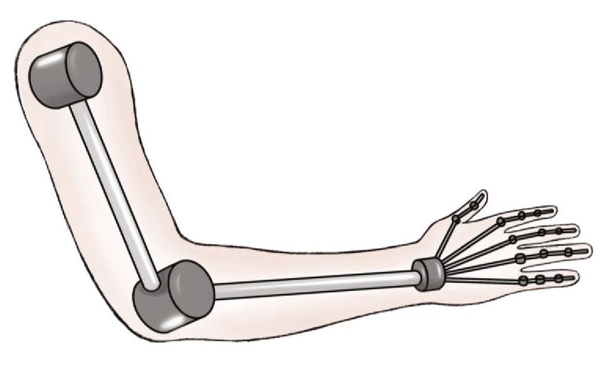
3.1. Anatomy of the Human Hand. The human hand has five while more powerful actuators can be used. For example, the
fingers—index finger, middle finger, ring finger, little finger DIST-Hand [22, 27] places 20 DC motors with a 2 kg·cm out-
and thumb. The anatomy of the human hand reveals that it put torque into a single-motor package outside the hand. The
is composed primarily of bones; there are a total of 27 bones, DEXMART Hand [28] employs 20 motors on the forearm,
which can be roughly divided into three categories: carpal and therefore, the hand structure is simplified, which pro-
bones, metacarpal bones, and phalanges [5]. Carpal bones vides more space for sensor integration and a more anthro-
are composed of eight bones, and they are responsible for pomorphic weight distribution. The HAP tendon drive
the overall movement of the palm and fingers. Metacarpal robotic hand is equipped with actuators on both the forearm
bones comprise five bones that connect carpals and phalan- and hand. For example, the RoboRay Hand [29] has seven
ges, and they support objects when grasping them. The high payload motors in the forearm and five small motors
remaining 14 bones are called phalanges, a thumb contains in the palm for high-powered grasping and precise grasping.
two phalanges, and the four fingers each contain three pha- The bioinspired hand [20] used forearm-mounted motors to
langes. These phalanges are the most important and complex drive the MCP joints and palm-mounted motors to drive the
parts of the human hand, and they are responsible for grasp- coupled PIP and DIP joints. In general, IAP is chosen for bet-
ing objects and gesturing in daily activities [18, 19]. ter modularity of the robotic hands; EAP allows the use larger
Parts of the bone connecting to the other bone are called actuators for greater gripping force, while the remaining
joints. The joints in the human hand are divided into carpo- hand space can be spared to install more sensors; HAP is
metacarpal (CMC) joints, metacarpal phalangeal (MCP) more suitable for the cases in which the convenience of
joints, and interphalangeal (IP) joints. The IP joints can be installation and gripping force of different joints need to be
divided into proximal interphalangeal (PIP) joints and distal considered.
interphalangeal (DIP) joints [6]. The CMC and MCP joints When the number of actuators is less than the DOFs, the
have two DOFs, i.e., flexion/extension and abduction/adduc- robotic system is called an underactuated system. Underactu-
tion, respectively, while the IP joints have only one DOF, i.e., ated systems are often used in tendon drive robotic hands to
flexion/extension. The four fingers each contain the DIP, reduce the number of actuators and simplify the structure
PIP, and MCP joints, while the thumb contains the IP, and to allow adaptive grasping. For example, the RTR II hand
MCP, and CMC joints, and thus, each of the four fingers [30] has three fingers; each of which uses only one tendon to4 Cyborg and Bionic Systems
operate three joints simultaneously. The force exerted on the principle of grasping an object is that the fingers start to
tendon produces a corresponding moment in each joint axis move when the actuator provides the driving force, and when
that is proportional to the joint pulley radius. Setting the joint all fingers are in contact with the object, the link starts to
pulley radius and spring stiffness ensures that the joints move rotate, which keeps the fingers moving until the object is
in the sequence of the MCP joint, PIP joint, and DIP joint to enveloped by the fingers. The link drive for fingers can make
achieve adaptive grasping. Jing et al. [31] designed a five- good use of its structural features while providing better grip-
finger prosthetic hand with only three actuators; however, ping stability. However, the design is complicated, and the
they could achieve 13 grasping patterns. movement is fixed after the design is finalized.
3.2.2. Gear Drive in Robotic Hands. The gear drive has high 3.2.4. Fluid Drive in Robotic Hands. Fluid actuators have a
precision and can achieve large reduction ratios. It is there- large output force per unit volume, and therefore, they are
fore often used in robotic hands to obtain larger grasping used for robotic hands that require a large grasping force.
forces and execute more accurate grasping tasks. The NTU The fluid actuator has lower friction in the actuator itself.
hand [32, 33] has five fingers, and a multistage spur gear sys- ARMAR’s Hand [40] has 5 fingers and 11 joints, of which 8
tem forms the structure of the fingers. The gear system has a are active and 3 are passive. All active joints are actuated by
reduction ratio of approximately 100 : 1 at the middle and small flexible fluid actuators. As a result, the robotic hand
proximal finger segments, and a reduction ratio of approxi- has the maximum grasping force of 110 N. The ZJUT hand
mately 1000 : 1 at the finger base segment. Therefore, the [41] has a flexible pneumatic actuator (FPA) placed at each
hand can grasp objects up to 1 kg. However, the hand is fully joint to control the movement of the joint. Because the joint
actuated with 17 DOFs driven by 17 actuators and the actu- is driven directly by the FPA, the torque output is more accu-
ators, gears, potentiometers, and tactile sensors are integrated rate, and it reduces friction and vibration. The Vanderbilt
in each finger; therefore, the overall weight is large (1569 g). hand [42] has 17 coupling DOFs and is driven by five pneu-
Hirano et al. [34] designed a five-finger robotic hand that also matic actuators. The pneumatic actuators are placed on the
uses spur gears, and 67 gears made using a 3D printer. Mean- proximal side of the forearm, which allows for a larger
while, two special gear mechanisms with different underactu- arrangement. Therefore, a higher-stroke, larger-capacity cyl-
ated movements were proposed to allow the entire hand to be inder is selected to provide forces of up to 40 N to the finger
controlled using only six actuators for 15 joints, which joint and 60 N to the thumb joint.
resulted in lower cost and lighter weight (458 g). Collahuazo
and Ordoñez [35] and Krausz et al. [36] designed hands with 3.2.5. Other Drive Methods in Robotic Hands. DLR-Hand II
a set of bevel gears at MCP joints to convert motor rotation [15, 43, 44], DLR-HIT II [45], SPRING Hand [24], and
into internal flexion/extension of the fingers and thumb. Intrinsic Hand [46] use a belt drive, but only as an auxiliary
The Tokyo-TECH 100 N Hand II [37] presents an improved drive method. Takaki and Omata [47] designed a robotic
force amplification drive that contains a turbine and worm hand that uses a screw drive in the thumb. Chain drive
gear. This mechanism can amplify torque at any joint while systems are large and have high installation requirements,
increasing the ROM of each joint and reducing the size of and therefore, they are not commonly used in humanoid
the hand. In general, the multistage spur gear system and robotic hands.
worm gear can improve the transmission reduction ratio
for greater gripping force. In order to improve the stability 3.3. Effect of Different Drive Methods on Robotic Hands. The
of the grip, the self-locking function of the worm gear can robotic hand is located at the front of the arm, and therefore,
be considered. Due to the shape of the actuator, the actuator a light weight can effectively reduce the inertial force. Mean-
at the finger joint is generally arranged along the direction while, if the robotic hand is used instead of a human pros-
of the finger, so bevel gears can be an option to change thetic hand, the heavy weight will cause discomfort, and
the drive direction. thus, the weight of the robotic hand needs to be minimized.
The weight of a humanoid robotic hand contains the weight
3.2.3. Link Drive in Robotic Hands. The finger structure of the of the hand structure, actuator, and drive system. Because of
link drive robotic hand comprises the drive linkage, and the complexity of the robotic hand, the effect of a single factor
therefore, the overall number of parts can be reduced. The on the overall weight of the hand is not known. Therefore,
TUAT/Karlsruhe hand [38] consists of links, and the link the remaining factors are unified to obtain the trend of the
system consists of link plates and link rods. Because parts influence of a single factor on weight. Therefore, we com-
of the link plates are movable, the mechanism can automati- pared the weights of the currently available five-finger,
cally and uniformly adjust the grasping force by adjusting the metal-based, IAP, HAP, and EAP tendons drive robotic
rotation angle of the actuators according to the size and soft- hands and the IAP gear drive robotic hands based on the
ness of the object. We previously discussed an underactuated number of actuators and the drive method. The specifica-
tendon drive system and a link drive that can achieve under- tions of the robotic hands are summarized in Table 1, and
actuated control. The Keio Hand [39] can use a single actua- the results of the comparison are shown in Figure 1.
tor to drive 15 joints of the five fingers simultaneously. The The comparison results indicate that the overall weight of
hand uses a five-finger underactuated link mechanism that the robotic hand tends to increase as the number of actuators
can envelop complex-shaped objects and adjust the grasping increases. Some tendon drive robotic hands weigh less than
force distribution according to the size of the object. The 400 g; however, all gear drive robotic hands weigh more thanTable 1: Specifications of humanoid robotic hands with different drive methods.
Cyborg and Bionic Systems
No. Name Fingers Joints/DOFs/actuators Actuation configuration Transmission mechanism Weight (g) Ref.
(1) SMARTHAND 5 16/16/4 DC motor/IAP Tendon 520 [26]
(2) Mitsui et al. 5 15/5/5 DC motor/ IAP Tendon+pulley 440 [48]
(3) Prosthetic hand 5 11/6/6 DC motor/IAP Tendon+pulley+linkage+gear 401 [49]
(4) DLR-HIT II 5 20/15/15 DC motor/IAP Tendon+timing belt 1500 [50] [51]
(5) Vanderbilt hand 5 16/16/5 DC motor+servomotor/HAP Tendon+routing 580 [52]
(6) Takaki & Omata 5 13/13/5 DC motor/HAP Tendon+pulley+screw 328 [47]
(7) RCH-1 5 16/16/6 DC motor/HAP Tendon 320 [53] [54]
(8) CyberHand 5 16/16/6 DC motor/HAP Tendon+pulley 360 [55]
(9) Bio-inspired 5 15/20/11 DC motor/HAP Tendon+pulley+screw 500 [20]
(10) EMG 5 15/15/10 Servomotor/HAP Tendon +pulley 1207 [56]
(11) Zollo et al. 5 15/16/5 DC motor/EAP Tendon+pulley+worm gear+screw 330 [57]
(12) Seki et al. 5 18/13/10 Servomotor/EAP Tendon 350 [58]
(13) Xu & Todorov 5 15/20/10 Servomotor/EAP Tendon+pulley 942 [59]
(14) Anthrobot-2 5 20/16/16 Servomotor/EAP Tendon+pulley 794 [60] [61]
(15) HIT/DLR 5 13/9/3 DC motor/IAP Bevel gear+harmonic gear+linkage 500 [62] [63]
(16) SSSA-MyHand 5 10/4/3 DC motor/IAP Worm/spur/bevel gear+linkage 478 [64]
(17) Koganezawa & Ito 5 15/10/5 DC motor/IAP Planetary/worm gear+linkage+timing belt 1400 [65]
(18) Krausz et al. 5 10/6/6 DC motor/IAP Worm/spur/bevel gear+timing belt 584 [36]
(19) Gifu Hand I 5 20/16/16 Servomotor/IAP Bevel gear 1226 [66]
(20) Gifu Hand II 5 20/16/16 Servomotor/IAP Face gear 1400 [67]
(21) Gifu Hand III 5 20/16/16 Servomotor/IAP Face gear 1400 [68]
(22) NTU 5 17/17/17 DC motor/IAP Spur gear 1569 [32] [33]
56 Cyborg and Bionic Systems
1800
1600 1500 1569
1400
1400 1400
1400
1200 1207
1226
Weight (g)
1000
942
800
584
600 580
500 520 500
440
400 478 401 350
360
200 328
250 320
0
0 2 4 6 8 10 12 14 16 18
Number of actuators
Tendon drive robotic hand (IAP) Tendon drive robotic hand (HAP)
Gear drive robotic hand (IAP) Tendon drive robotic hand (EAP)
Figure 1: Comparison of the weight of humanoid robotic hands with different drive methods.
400 g. This is because the tendons and pulleys of the tendon elevation (flexion) and posterior elevation (extension) of the
drive system are simple and lightweight compared to the upper arm centered on the medial and lateral axes of the
gears of the gear drive system. Further, for the IAP robotic joint. The lateral elevation of the upper arm (abduction)
hands, when the number of actuators is small, the weight of and movement towards the midline of a limb (adduction).
the structure and drive system accounts for a larger propor- The movement of twisting the upper arm outward (external
tion of the overall weight, but when the number of actuators rotation) and inward (internal rotation) around the upper
is large, the weight of the actuators accounts for a larger pro- arm. Anterior elevation (flexion) and posterior elevation
portion. Thus, as the number of actuators increases, the dif- (extension) of the upper arm are centered on the medial
ference in weight between the tendon drive and gear drive and lateral axes of the joint. Lateral elevation (abduction) of
robotic hands decreases. For the IAP, HAP, and EAP tendons the upper arm is centered on the anterior-posterior axis,
drive robotic hands, as the number of actuators increases, the and the movement attracts the elevated upper arm to the
difference in weight increases. trunk (adduction). The movement of twisting the upper
The fingertip force of the available robotic hands is very arm outward (external rotation) and the movement of twist-
different. There are robotic hands with a fingertip force of less ing the upper arm inward (internal rotation) around the
than 5 N, such as Pisa/IIT SoftHand 2 [25], Gifu Hand I [66], upper arm are observed.
Gifu Hand III [68], and CyberHand [55], and robotic hands The elbow joint is a uniaxial joint that can only perform
with a fingertip force close to that of human fingers, such as flexion and extension movements. In this case, there is only
Tokyo-TECH 100 N HAND [37]. The fingertip force is one movement axis, which runs horizontally across the elbow
determined by the output torque of the actuator and the joint. In the forearm, the forearm bones—the radius and
reduction ratio of the drive system. The fluid drive has higher ulna—are arranged almost in parallel and form an axis. The
energy output density and provides greater output torque for forearm bone allows for twisting movements (pronation
the same volume, while multistage gear drive systems can and supination) of the forearm. Meanwhile, the radius is
achieve a larger reduction ratio than other drive methods. shaped to move around the ulna. The wrist joint is a biaxial
They can be applied to robotic hands to increase gripping joint, which enables the bending and stretching movements
force. of the wrist. These moves are relatively large. The movement
of tilting sideways, i.e., the movement of abduction and
adduction, are relatively small [70, 71].
4. Humanoid Robotic Arms
4.2. Main Drive Methods in Humanoid Robotic Arms
4.1. Anatomy of the Human Arm. The total weight of the
human arm is approximately 5.2% of the body weight, of 4.2.1. Tendon Drive in Robotic Arms. The actuator of a
which the upper arm accounts for 3%, the forearm accounts robotic arm is placed in the arm; however, because of the
for 1.6%, and the hands account for 0.6% of the body weight large distance of the center of mass (COM) from the shoulder
[69]. The human arm has seven DOFs, except for the hand. base, a large inertial force is generated during movement. To
The shoulder joint is a ball-and-socket joint, with the anterior minimize the inertial force, a tendon drive robotic arm isCyborg and Bionic Systems 7
Table 2: Specifications of humanoid robotic arms with different drive methods.
No. Name DOFs/actuators Transmission mechanism Weight (kg) Payload (kg) Payload/weight Ref.
(1) MIA 7/14 Harmonic gear 25.0 3.0 0.12 [85, 86]
(2) Quigley et al. 7/7 Tendon + Timing Belt 11.4 2.0 0.18 [87]
(3) LIMS 7/7 Tendon + Timing Belt 5.5 2.9 0.53 [72, 73]
(4) Tsumaki et al. 7/8 Tendon 2.9 1.5 0.52 [88]
(5) LWH 8/8 Direct drive 3.5 0.3 0.09 [89]
(6) Li et al. 7/7 Tendon 2.2 1.5 0.68 [76, 77]
(7) KINOVA Gen2 7/7 Harmonic gear 5.5 2.4 0.44 [90]
(8) KINOVA Gen3 7/7 Harmonic gear 8.3 4.5 0.54 [91]
(9) WAM Arm 7/7 Tendon 27.0 3.0 0.11 [92]
(10) UR5 6/6 Harmonic gear 18.4 5.0 0.27
(11) Barrett 7/7 Tendon 25.0 4.0 0.16
(12) KR Agilus 6 R700 6/6 Harmonic gear 50.0 6.0 0.12
(13) LWA Powerball 6/6 Harmonic gear 12.5 6.0 0.48
[93]
(14) LWAPA10 7/7 Harmonic gear 35.0 10.0 0.29
(15) SIA5F 7/7 Harmonic gear 30.0 5.0 0.17
(16) VS-6577G-B 6/6 Harmonic gear 36.0 7.0 0.19
(17) LBR iiwa7R800 7 7/7 Harmonic gear 22.3 7.0 0.31
(18) LWR III 7/7 Harmonic gear 14.0 14.0 1.00 [94]
considered by placing the actuator as close as possible to the weight of the robot arm is only 2.2 kg; however, the maxi-
shoulder base. For example, the LIMS arm [72, 73] and the mum weight that can be lifted is 1.5 kg.
MYOROBOTICS arm [74] place the actuator on the shoul-
der joint. Thus, the COM of the LIMS arm is located only 4.2.2. Gear Drive in Robotic Arms. A gear can produce a
169 mm from the shoulder base, and it has a reduced inertia mechanical advantage through a gear ratio, and the geared
force of 0.57 kg·m2, which is similar to the inertia force of the devices can change the speed, torque, and direction of a
human arm, while the MYOROBOTICS arm has a lower power source. The Animator arm [78] uses a gearbox com-
inertia force of 0.2–0.4 kg·m2. prising multiple spur gears to change the rotational speed
In an uncoupled drive system, in which one motor drives ratio and torque ratio of the input and output. Bennett
one joint separately, during the single-joint motion, all the et al. [79] designed a robotic arm with a set of worm gears
other motors are in standby, which can be considered a waste in the wrist, thereby providing a 30 : 1 ratio in a smaller size.
of motor resources. However, a coupled drive system can The 7R arm [80] has seven joints with a cylindrical gear used
reallocate motor resources to achieve greater payload. It is in joint 1, a double bevel gear used in joint 2, and a bevel gear
easier to use tendon drive implement coupled drive than used in joints 3 and 5. Both joints 1 and 2 use a 1.5 : 1 reduc-
the other drive methods due to the flexibility of its motor tion ratio, and therefore, the maximum torque is greater than
arrangement and wire routing. 60 Nm. The harmonic gear drive has the advantages of high
A coupled tendon drive system is a drive system with two transmission ratio, high transmission efficiency, high trans-
or more actuators working simultaneously during a single- mission accuracy and low noise, so it is widely used in
joint motion. A coupled tendon drive system can reduce commercial robotic arms.
the size and weight of the structure by using smaller actuators
with the same torque output conditions and output a larger 4.2.3. Fluid Drive in Robotic Arms. Kawashima et al. [81]
joint torque with the same actuator. Coupled tendon drive designed a 6-DOF pneumatic robotic arm comprising a 2-
systems are used for tendon drive robotic arms. For example, DOF shoulder joint, 2-DOF elbow joint, and 2-DOF wrist
the CT Arm [75] was first applied with a coupled tendon joint. Each DOF is supported by two pneumatic artificial mus-
drive, which is driven by six tendons to three joints, where cles (PARMs) for motion and power transmission. The For-
tendon 1 and tendon 2 connect joint 1; tendon 3 and tendon ceRobot arm [82] also uses a pneumatic drive with four
4 connect joints 1 and 2; and tendons 5 and 6 connect joints pneumatic cylinders mounted on the shoulder. Because the
1, 2, and 3. Li et al. [76, 77] designed a 7-DOF robotic maximum pressure of the air compressor used is 6.5 kgf/cm2,
arm with a modular coupled tendon drive system, with a a maximum torque of 88 Nm can be generated in the shoulder.
2-motor 2-DOF (2M2D) coupling drive module for the
elbow joint and wrist joint, and a 3-motor 3-DOF (3M3D) 4.2.4. Other Drive Methods in Robotic Arms. The LIMS arm
coupling drive module for the shoulder joint. Here, the n [73] employs a belt drive used in the shoulder to achieve an
-motor n-DOF coupling drive module represents n degrees additional reduction ratio in addition to the reduction by
of freedom that are coupled by n motors. Thus, the total the tension amplifying mechanism. Bennett et al. [79]8 Cyborg and Bionic Systems
16
14
(18) 1.00 (14) 0.29
12
10 (17) 0.31
Payload (kg)
(13) 0.48 (12) 0.12
8 (15) 0.17
(8) 0.54
(11) 0.16
6 (3) 0.53
(4) 0.52 (16) 0.19
4
(6) 0.68 (7) 0.44 (10) 0.27
2 (5) 0.09
(1) 0.12 (9) 0.11
(2) 0.18
0
0 10 20 30 40 50 60
Weight (kg)
Research laboratory robotic arm (Tendon) Commercial robotic arm (Tendon)
Reaearch laboratory robotic arm (Harmonic gear) Commercial robotic arm (Harmonic gear)
Research laboratory robotic arm (Direct drive)
Figure 2: Comparison of the weight and payload of research robotic arms and commercial robotic arms with different drive methods, where
the red line represents the payload weight as half of the arm’s self-weight.
4.8% 5.0% 3.7% 1.9% 3.9% 2.0%
4.8% 5.0% 3.7%
5.6%
10.0% 17.6%
19.0%
42.9% 10.0% 50.0% 55.6%
29.6% 62.7%
13.7%
9.5%
20.0%
19.0%
Shoulder joint (total: 21) Wrist joint (total: 20) MCP (thumb/total: 54) IP (thumb/total: 51)
4.5%
9.1%
4.5%
9.1% 45.5%
9.1%
3.5% 5.3% 1.8% 4.0% 3.5% 1.8% 1.8%
18.2% 4.0%
1.8%
Elbow joint (total: 22)
10.0%
Tendon drive Belt drive 26.3%
29.8% 57.9% 18.0% 64.0% 59.6%
Gear drive Chain drive
Link drive Screw drive 7.0%
Fluid drive Direct drive MCP (fingers/total: 57) PIP (fingers/total: 50) DIP (fingers/total: 57)
Figure 3: Proportion of each drive method used in humanoid robotic upper limb joints.
designed a robotic arm with a three-stage transmission com- robot [84] use four-bar linkages on elbow joints with a coun-
prising two chain stages (ratio of 5.1 : 1 and 2.9 : 1, respec- terbalance mechanism (CBM).
tively) followed by a tendon drive output stage (with a ratio
of 2.4 : 1) in the elbow. The chain drive is selected for the first 4.3. Effect of Different Drive Methods in Robotic Arms. The
two stages because of its high efficiency and compact nature. main drive methods of the robotic arm are tendon and gear
The arms for a collaborative robot [83] and an industrial drives. The tendon drive has the advantages of light weightCyborg and Bionic Systems 9
and long-distance transmission that allows the actuators to often used in the MCP joints of the thumb and fingers, and
be arranged near the shoulder to reduce the inertia. The gear link drives are often used in the PIP and DIP joints of the fin-
drive has the advantages of high transmission ratio, high gers, the IP joint of the thumb, and the elbow joint; and
transmission efficiency, and high transmission accuracy. finally, belt drives are widely used in the shoulder joint
Harmonic gears have the advantages of smaller size, lighter (shown in Figure 3). According to the structural characteris-
weight, and higher transmission ratio compared to conven- tics of the robotic upper limb and the tasks to be performed,
tional gears, thus allowing for greater output torque with less suitable drive methods are selected to ensure that the mech-
weight, as well as lower inertia forces. anism has a more desirable design output. A compound drive
The weight of robotic arms affects their applications system comprising multiple drive methods considers the
where lightweight robotic arms can be used as prosthetic advantages of different drive methods and is widely used in
arms for the disabled, whereas heavy robotic arms are used robotic mechanisms. In addition, the reasonable use of the
in factory production. Further, there is a relationship underdrive as well as the coupled drive can sometimes fur-
between the weight and the payload of the robotic arm, and ther optimize the robotic mechanism.
theoretically, as the weight of the robot arm increases, the
payload also increases. As a researcher, the main purpose is
to make the payload capacity per unit weight as high as pos- Conflicts of Interest
sible. The weight and payload of the research robotic arms
The authors declare no conflict of interest.
and commercial robotic arms are summarized in Table 2,
and the comparison of weight and payload is shown in
Figure 2. Acknowledgments
The results show that the ratio of the payload to the
weight for general robots is less than 0.5, while that for better This research was supported in part by JSPS KAKENHI
performing robotic arms is close to or slightly more than 0.5. grant numbers JP18H03761, JP19K14941, JP19K12877, and
The LWR III arm [94] has a self-weight of 14 kg and a max- 20J14065.
imum load of 14 kg, which achieves a load-to-weight ratio of
1. The use of harmonic drive gears of robust ILM motors
with high power density and light materials and as a conse- References
quent light-weight-oriented mechanical design are key issues
[1] K. Dautenhahn, “Socially intelligent robots: dimensions of
for reaching this goal. The LWH arm has the smallest pay- human-robot interaction,” Philosophical Transactions of the
load capacity per unit weight, mainly because the robotic Royal Society B: Biological Sciences, vol. 362, no. 1480,
arm uses direct drive, and the motor torque is transferred pp. 679–704, 2007.
to the joint in a 1 : 1 transmission ratio. [2] S. Martínez, C. A. Monje, A. Jardón, P. Pierro, C. Balaguer, and
In order to increase the load capacity per unit weight of D. Muñoz, “TEO: full-size humanoid robot design powered by
the robotic arm, two approaches can be considered. One is a fuel cell system,” Cybernetics and Systems, vol. 43, no. 3,
to reduce the weight of the robotic arm itself, such as the pp. 163–180, 2012.
use of tendon drive, the use of lightweight materials; The [3] K. Kaneko, F. Kanehiro, S. Kajita et al., “Design of prototype
other is to increase the output torque, which can generally humanoid robotics platform for HRP,” in IEEE/RSJ Interna-
be achieved by increasing the transmission ratio. Most com- tional Conference on Intelligent Robots and System, pp. 2431–
mercial robotic arms use harmonic gear to obtain a high 2436, Lausanne, Switzerland, Septemebr-October 2002.
transmission ratio. In general, prosthetic arms are required [4] N. G. Tsagarakis, G. Metta, G. Sandini et al., “iCub: the design
to be as lightweight as possible to improve wearability. There- and realization of an open humanoid platform for cognitive
fore, the former approach is more applicable to the develop- and neuroscience research,” Advanced Robotics, vol. 21,
ment of prostheses that reduce weight while ensuring the no. 10, pp. 1151–1175, 2007.
same load capacity. The use of tendon drive can well achieve [5] A. Kumar, T. S. Mundra, and A. Kumar, Anatomy of the hand
the lightweight of the robotic arm by arranging the actuator BT - Encyclopedia of Biometrics, S. Z. Li and A. K. Jain, Eds.,
Springer, Boston, MA, USA, 2015.
close to the shoulder base to reduce the inertia. In addition,
the elasticity of the tendons can improve the safety of the [6] T. Rhee, U. Neumann, and J. P. Lewis, Human Hand Modeling
from Surface Anatomy, 1- Assoc. Comput: Mach., 2006.
robotic arm to a certain extent. Industrial robotic arms are
less demanding on lightweight than transmission accuracy [7] J. T. Belter, J. L. Segil, A. M. Dollar, and R. F. Weir, “Mechan-
ical design and performance specifications of anthropomor-
and maximum payload. The latter approach is more suitable
phic prosthetic hands: a review,” Journal of Rehabilitation
for industrial robotic arms. Research and Development, vol. 50, no. 5, pp. 599–618, 2013.
[8] N. M. Bajaj, A. J. Spiers, and A. M. Dollar, “State of the art in
5. Conclusions artificial wrists: a review of prosthetic and robotic wrist
design,” IEEE Transactions on Robotics, vol. 35, no. 1,
This study focuses on the application of different drive pp. 261–277, 2019.
methods to humanoid robotic upper limbs. A statistical [9] J. E. Parada Puig, N. E. N. Rodriguez, and M. Ceccarelli, “A
survey of the main drive methods used in the humanoid methodology for the design of robotic hands with multiple fin-
robotic upper limb joints showed that tendon drives are most gers,” International Journal of Advanced Robotic Systems,
commonly used in the robotic upper limb, gear drives are vol. 5, no. 2, pp. 22–184, 2008.10 Cyborg and Bionic Systems
[10] M. De Volder and D. Reynaerts, “Pneumatic and hydraulic [27] A. Caffaz and G. Cannata, “The design and development of the
microactuators: a review,” Journal of Micromechanics and Dist-hand dextrous gripper,” in Proceedings 1998 IEEE
Microengineering, vol. 20, no. 4, p. 043001, 2010. International Conference on Robotics and Automation (Cat.
[11] V. B. Bhandari, Design of Machine Elements, Tata McGraw No.98CH36146), Leuven, Belgium, May 1998.
Hill Education Private Limited, 2010. [28] A. Wedler, M. Chalon, A. Baumann, W. Bertleff, A. Beyer, and
[12] “Difference between friction drive and engagement drive,” R. Burger, DLRs space qualifiable multi-figered DEXHAND,
2021, http://www.differencebox.com/engineering/difference- Robotics.Estec.Esa.Int, 2011.
between-friction-drive-and-engagement-drive/. [29] Y.-J. Kim, Y. Lee, J. Kim et al., “RoboRay hand: a highly back-
[13] L. Wen, Y. Li, M. Cong, H. Lang, and Y. Du, “Design and drivable robotic hand with sensorless contact force measure-
optimization of a tendon-driven robotic hand,” in 2017 IEEE ments,” in 2014 IEEE International Conference on Robotics
International Conference on Industrial Technology (ICIT), and Automation (ICRA), pp. 6712–6718, Hong Kong, China,
pp. 767–772, Toronto, ON, Canada, March 2017. May 2014.
[14] A. Schmitz, U. Pattacini, F. Nori, L. Natale, G. Metta, and [30] B. Massa, S. Roccella, M. C. Carrozza, and P. Dario, “Design
G. Sandini, “Design, realization and sensorization of the and development of an underactuated prosthetic hand,” in
dexterous iCub hand,” in 2010 10th IEEE-RAS International Proceedings 2002 IEEE International Conference on Robotics
Conference on Humanoid Robots, pp. 186–191, Nashville, and Automation (Cat. No.02CH37292), pp. 3374–3379,
TN, USA, December 2010. Washington, DC, USA, May 2002.
[15] C. Borst, M. Fischer, S. Haidacher, H. Liu, and G. Hirzinger, [31] X. Jing, X. Yong, Y. Jiang, G. Li, and H. Yokoi, “Anthropo-
“DLR hand II: experiments and experiences with an anthropo- morphic prosthetic hand with combination of light weight
morphic hand,” in 2003 IEEE International Conference on and diversiform motions,” Applied Sciences, vol. 9, no. 20,
Robotics and Automation (Cat. No.03CH37422), pp. 702– p. 4203, 2019.
707, Taipei, Taiwan, September 2003. [32] L.-R. Lin and H.-P. Huang, “Integrating fuzzy control of the
[16] A. F. Al-Dwairi, S. E. Al-Lubani, and M. A. Al-Nawafle, “Ana- dexterous National Taiwan University (NTU) hand,”
lytical synthesis of crank-Rocker and double-crank mecha- IEEE/ASME Transactions on Mechatronics, vol. 1, no. 3,
nisms with minimax link-length ratios,” in Proceedings of the pp. 216–229, 1996.
XXXVII Summer School - Conference, pp. 192–203, Russia, [33] L. Lin and H. Huang, “NTU Hand: a new design of dexterous
2009. hands,” Journal of Mechanical Design, vol. 120, no. 2, pp. 282–
[17] “Power transmission compact catalogue,” 2019, https://www 292, 1998.
.optibelt.com/fileadmin/pdf/kataloge/Optibelt-Compact- [34] Y. Hirano, K. Akiyama, and R. Ozawa, “Design of low-cost and
Catalogue-Power-Transmission.pdf. easy-assemblable robotic hands with stiff and elastic gear
[18] C. L. Taylor and R. J. Schwarz, “The anatomy and mechanics of trains,” in 2016 IEEE/RSJ International Conference on Intelli-
the humanoid hand,” Robot, vol. 14, no. 4, pp. 437–443, 1996. gent Robots and Systems (IROS), pp. 864–870, Daejeon, Korea
[19] “Hand,” 2020, https://www.britannica.com/science/hand- (South), October 2016.
anatomy. [35] S. Javier Patricio Collahuazo and M. Esteban Fernando
[20] M. Controzzi, C. Cipriani, B. Jehenne, M. Donati, and M. C. Ordonez, “Design and construction of a robot hand acti-
Carrozza, “Bio-inspired mechanical design of a tendon- vated by electromyographic signals,” in 2012 IEEE Interna-
driven dexterous prosthetic hand,” in 2010 Annual Interna- tional Symposium on Robotic and Sensors Environments
tional Conference of the IEEE Engineering in Medicine and Proceedings, pp. 25–30, Magdeburg, Germany, November
Biology, pp. 499–502, Buenos Aires, Argentina, August- 2012.
September 2010. [36] N. E. Krausz, R. A. L. Rorrer, and R. F. F. Weir, “Design and
[21] K. J. Bretz, Á. Jobbágy, and K. Bretz, “Force measurement of fabrication of a six degree-of-freedom open source hand,”
hand and fingers,” Biomechanica Hungarica, vol. 3, no. 1, IEEE Transactions on Neural Systems and Rehabilitation Engi-
pp. 61–66, 2010. neering, vol. 24, no. 5, pp. 562–572, 2016.
[22] A. Caffaz, G. Casalino, G. Cannata, G. Panin, and E. Massucco, [37] T. Takayama, T. Yamana, and T. Omata, “Three-Fingered
“The dist-hand, an anthropomorphic, fully sensorized dexter- eight-DOF hand that exerts 100-N grasping force with force-
ous gripper,” in First IEEE-RAS International Conference on magnification drive,” IEEE/ASME Transactions on Mechatro-
Humanoid Robots, Cambridge, MA, USA, 2000. nics, vol. 17, no. 2, pp. 218–227, 2012.
[23] H. Liu, D. Yang, S. Fan, and H. Cai, “On the development of [38] N. Fukaya, T. Asfour, R. Dillmann, and S. Toyama, “Develop-
intrinsically-actuated, multisensory dexterous robotic hands,” ment of a five-finger dexterous hand without feedback control:
ROBOMECH Journal, vol. 3, no. 1, 2016. the TUAT/Karlsruhe humanoid hand,” in 2013 IEEE/RSJ
[24] A. Lindgreen, “Corruption and Unethical Behavior: Report on International Conference on Intelligent Robots and Systems,
a Set of Danish Guidelines,” Journal of Business Ethics, vol. 51, pp. 4533–4540, Tokyo, Japan, November 2013.
no. 1, pp. 31–39, 2004. [39] Y. Kamikawa and T. Maeno, “Underactuated five-finger
[25] C. D. Santina, C. Piazza, G. Grioli, M. G. Catalano, and prosthetic hand inspired by grasping force distribution of
A. Bicchi, “Toward dexterous manipulation with augmented humans,” in 2008 IEEE/RSJ International Conference on Intel-
adaptive synergies: the Pisa/IIT SoftHand 2,” IEEE Transac- ligent Robots and Systems, pp. 717–722, Nice, France, Septem-
tions on Robotics, vol. 34, no. 5, pp. 1141–1156, 2018. ber 2008.
[26] C. Cipriani, M. Controzzi, and M. C. Carrozza, “Objectives, [40] A. Kargov, T. Asfour, C. Pylatiuk et al., “Development of an
criteria and methods for the design of the SmartHand anthropomorphic hand for a mobile assistive robot,” in 9th
transradial prosthesis,” Robotica, vol. 28, no. 6, pp. 919– International Conference on Rehabilitation Robotics, 2005.
927, 2010. ICORR 2005, pp. 182–186, Chicago, IL, USA, June-July 2005.Cyborg and Bionic Systems 11
[41] Z. Wang, L. Zhang, G. Bao, S. Qian, and Q. Yang, “Design and [55] M. C. Carrozza, G. Cappiello, S. Micera, B. B. Edin, L. Beccai,
control of integrated pneumatic dexterous robot finger,” Jour- and C. Cipriani, “Design of a cybernetic hand for perception
nal of Central South University of Technology, vol. 18, no. 4, and action,” Biological Cybernetics, vol. 95, no. 6, pp. 629–
pp. 1105–1114, 2011. 644, 2006.
[42] K. B. Fite, T. J. Withrow, K. W. Wait, and M. Goldfarb, “A [56] A. Hernandez Arieta, R. Katoh, H. Yokoi, and Y. Wenwei,
gas-actuated anthropomorphic transhumeral prosthesis,” “Development of a multi-DOF electromyography prosthetic
IEEE Transactions on Robotics, vol. 24, no. 1, pp. 159–169, system using the adaptive joint mechanism,” Applied Bionics
2007. and Biomechanics, vol. 3, no. 2, pp. 101–111, 2006.
[43] J. Butterfab, M. Grebenstein, H. Liu, and G. Hirzinger, “DLR- [57] L. Zollo, S. Roccella, E. Guglielmelli, M. C. Carrozza, and
hand II: next generation of a dextrous robot hand,” in Proceed- P. Dario, “Biomechatronic design and control of an anthropo-
ings 2001 ICRA. IEEE International Conference on Robotics morphic artificial hand for prosthetic and robotic applica-
and Automation (Cat. No.01CH37164), pp. 109–114, Seoul, tions,” IEEE/ASME Transactions on Mechatronics, vol. 12,
Korea (South), May 2001. no. 4, pp. 418–429, 2007.
[44] J. Butterfnr, M. Fischer, M. Grebenstein, S. Haidacher, and [58] T. Seki, T. Nakamura, R. Kato, S. Morishita, and H. Yokoi,
G. Hirzinger, “Design and experiences with DLR HAND II,” “Development of five-finger multi-DOF myoelectric hands
in Proceedings World Automation Congress, 2004, pp. 105– with a power allocation mechanism,” in 2013 IEEE Interna-
110, Seville, Spain, June-July 2004. tional Conference on Robotics and Automation, pp. 2054–
[45] H. Liu, K. Wu, P. Meusel, N. Seitz, G. Hirzinger, and 2059, Karlsruhe, Germany, May 2013.
W. Germany, “Multisensory five-finger dexterous hand: the [59] Z. Xu and E. Todorov, “Design of a highly biomimetic anthro-
DLR/HIT hand II,” in 2008 IEEE/RSJ International Conference pomorphic robotic hand towards artificial limb regeneration,”
on Intelligent Robots and Systems, pp. 22–26, Nice, France, in 2016 IEEE International Conference on Robotics and Automa-
September 2008. tion (ICRA), pp. 3485–3492, Stockholm, Sweden, May 2016.
[46] R. F. Weir, M. Mitchell, S. Clark et al., “The intrinsic hand–a [60] K. J. Kyriakopoulos, J. Van Riper, A. Zink, and H. E.
22 degree-of-freedom artificial hand-wrist replacement,” in Stephanou, “Kinematic analysis and position/force control
Proceedings Myoelectric Controls/Powered Prosthetics Sympo- of the anthrobot dextrous hand,” IEEE Transactions on
sium, Fredericton, New Brunswick, Canada, August 2008. Systems, Man, and Cybernetics, Part B (Cybernetics), vol. 27,
[47] T. Takaki and T. Omata, “High-performance anthropomor- no. 1, pp. 95–104, 1997.
phic robot hand with grasping-force-magnification mecha- [61] J. Vanriper, M. S. Ali, K. J. Kyriakopoulos, and H. E. Stepha-
nism,” IEEE/ASME Transactions on Mechatronics, vol. 16, nou, “Description and kinematic analysis of the anthrobot-2
no. 3, pp. 583–591, 2011. dextrous hand,” in Proceedings of the 1992 IEEE International
[48] K. Mitsui, R. Ozawa, and T. Kou, “An under-actuated robotic Symposium on Intelligent Control, pp. 299–305, Glasgow, UK,
hand for multiple grasps,” in 2013 IEEE/RSJ International August 1992.
Conference on Intelligent Robots and Systems, pp. 5475–5480, [62] X. H. Gao, M. H. Jin, L. Jiang et al., “The HIT/DLR dexterous
Tokyo, Japan, November 2013. hand: work in progress,” in 2003 IEEE International Confer-
[49] S. Y. Jung and I. Moon, “Grip force modeling of a tendon- ence on Robotics and Automation (Cat. No.03CH37422),
driven prosthetic hand,” in 2008 International Conference on pp. 3164–3168, Taipei, Taiwan, September 2003.
Control, Automation and Systems, pp. 2006–2009, Seoul, [63] H. Huang, L. Jiang, Y. Liu, L. Hou, H. Cai, and H. Liu, “The
Korea (South), October 2008. mechanical design and experiments of HIT/DLR prosthetic
[50] H. Liu, P. Meusel, G. Hirzinger, M. Jin, Y. Liu, and Z. Xie, “The hand,” in 2006 IEEE International Conference on Robotics
modular multisensory DLR-HIT-hand: hardware and soft- and Biomimetics, pp. 896–901, Kunming, China, December
ware architecture,” IEEE/ASME Transactions on Mechatro- 2006.
nics, vol. 13, no. 4, pp. 461–469, 2008. [64] M. Controzzi, F. Clemente, D. Barone, A. Ghionzoli, and
[51] H. Liu, K. Wu, P. Meusel et al., “Multisensory five-finger C. Cipriani, “The SSSA-MyHand: a dexterous lightweight
dexterous hand: the DLR/HIT hand II,” in 2008 IEEE/RSJ myoelectric hand prosthesis,” IEEE Transactions on Neural
International Conference on Intelligent Robots and Systems, Systems and Rehabilitation Engineering, vol. 25, no. 5,
pp. 3692–3697, Nice, France, September 2008. pp. 459–468, 2017.
[52] S. A. Dalley, T. E. Wiste, T. J. Withrow, and M. Goldfarb, [65] K. Koganezawa and A. Ito, “Artificial hand with stiffness
“Design of a multifunctional anthropomorphic prosthetic adjuster,” in 2014 IEEE/RSJ International Conference on Intel-
hand with extrinsic actuation,” IEEE/ASME Transactions on ligent Robots and Systems, Chicago, IL, USA, September 2016.
Mechatronics, vol. 14, no. 6, pp. 699–706, 2009. [66] H. Kawasaki and T. Komatsu, “Mechanism design of anthro-
[53] M. Zecca, S. Roccella, M. C. Carrozza et al., “On the develop- pomorphic robot hand: Gifu hand I,” Journal of Robotics and
ment of the emotion expression humanoid robot WE-4RII Mechatronics, vol. 11, no. 4, pp. 269–273, 1999.
with RCH-1,” in 4th IEEE/RAS International Conference on [67] H. Kawasaki, T. Komatsu, K. Uchiyama, and T. Kurimoto,
Humanoid Robots, 2004., pp. 235–252, Santa Monica, CA, “Dexterous anthropomorphic robot hand with distributed tac-
USA, November 2004. tile sensor: Gifu hand II,” IEEE/ASME Transactions on Mecha-
[54] S. Roccella, M. C. Carrozza, G. Cappiello et al., “Design, fabri- tronics, vol. 7, no. 3, pp. 296–303, 2002.
cation and preliminary results of a novel anthropomorphic [68] T. Mouri, H. Kawasaki, K. Yoshikawa, J. Takai, and S. Ito,
hand for humanoid robotics: RCH-1,” in 2004 IEEE/RSJ Inter- “Anthropomorphic robot hand : Gifu hand III,” in Int. Conf.
national Conference on Intelligent Robots and Systems (IROS) Control. Autom. Syst., Jeonbuk, Korea, 2002.
(IEEE Cat. No.04CH37566), pp. 266–271, Sendai, Japan, [69] R. F. Chandler, C. E. Clauser, J. T. McConville, H. M. Reyn-
September-October 2004. olds, and J. W. Young, Investigation of Inertial Properties of12 Cyborg and Bionic Systems
the Human Body, National Highway Traffic Safety Adminis- sive counterbalance mechanisms,” in 2016 IEEE/RSJ
tration, 1975. International Conference on Intelligent Robots and Systems
[70] A. M. S. F. Galhano and J. A. Tenreiro Machado, “Biomechan- (IROS), pp. 4344–4349, Daejeon, Korea (South), October 2016.
ical perspective for the kinematic analysis of robot manipula- [85] T. Motita and S. Sugano, “Development and evaluation of
tors,” Systems Analysis Modelling Simulation, vol. 36, no. 4, seven-D.O.F. MIA ARM,” in Proceedings of International
pp. 471–484, 2000. Conference on Robotics and Automation, pp. 462–467,
[71] T. Sobh and X. Xiong, Prototyping of robotic systems: Applica- Albuquerque, NM, USA, April 1997.
tions of design and implementation, Inf. Sci. Ref, 2012. [86] T. Morita, N. Tomita, T. Ueda, and S. Sugano, “Development
[72] Y. J. Kim, “Anthropomorphic low-inertia high-stiffness of force-controlled robot arm using mechanical impedance
manipulator for high-speed safe interaction,” IEEE Transac- adjuster,” Journal of the Robotics Society of Japan, vol. 16,
tions on Robotics, vol. 33, no. 6, pp. 1358–1374, 2017. no. 7, pp. 1001–1006, 1998.
[73] Y. J. Kim, “Design of low inertia manipulator with high stiff- [87] M. Quigley, A. Asbeck, and A. Ng, “A low-cost compliant
ness and strength using tension amplifying mechanisms,” in 7-DOF robotic manipulator,” in 2011 IEEE International
2015 IEEE/RSJ International Conference on Intelligent Robots Conference on Robotics and Automation, pp. 6051–6058,
and Systems (IROS), pp. 5850–5856, Hamburg, Germany, Shanghai, China, May 2011.
September 2015. [88] Y. Tsumaki, Y. Suzuki, N. Sasaki, E. Obara, and S. Kanazawa,
[74] C. Richter, S. Jentzsch, R. Hostettler et al., “Musculoskeletal “A 7-DOF wire-driven lightweight arm with wide wrist
robots: scalability in neural control,” IEEE Robotics & Automa- motion range,” in 2018 IEEE/RSJ International Conference on
tion Magazine, vol. 23, no. 4, pp. 128–137, 2016. Intelligent Robots and Systems (IROS), pp. 1–9, Madrid, Spain,
[75] S. Hirose and S. Ma, “Coupled tendon-driven multijoint October 2018.
manipulator,” in Proceedings. 1991 IEEE International Confer- [89] H. Yang, Y. Yan, S. Su, Z. Dong, and S. H. Ul Hassan, “LWH-
ence on Robotics and Automation, pp. 1268–1275, Sacramento, arm: a prototype of 8-DOF lightweight humanoid robot arm,”
CA, USA, April 1991. in 2019 3rd International Conference on Robotics and Automa-
[76] W. Li, P. Chen, D. Bai et al., “Modularization of 2- and 3-DOF tion Sciences (ICRAS), pp. 6–10, Wuhan, China, June 2019.
coupled tendon-driven joints,” IEEE Transactions on Robotics, [90] User Guide: KINOVA Gen2 ultra lightweight robot, Kinova
vol. 37, pp. 1–13, 2021. Inc., 2019, https://www.kinovarobotics.com/sites/default/
[77] W. Li, P. Chen, Y. Jiang, D. Bai, S. Togo, and H. Yokoi, “Struc- files/UG-009_KINOVA_Gen2_Ultra_lightweight_robot_
ture design of a tendon-driven robotic arm considering safety User_guide_EN_R02.pdf.
and durability,” in 2018 IEEE International Conference on [91] User Guide: KINOVA Gen3 ultra lightweight robot, Kinova
Intelligence and Safety for Robotics (ISR), pp. 71–76, Shenyang, Inc., 2018, https://www.kinovarobotics.com/sites/default/
China, August 2018. files/UG-014_KINOVA_Gen3_Ultra_lightweight_robot-
[78] A. Rahman, A. H. Khan, T. Ahmed, and M. Sajjad, “Design, User_guide_EN_R01.pdf.
analysis and implementation of a robotic arm- the animator,” [92] WAM arm User’s Guide, Barrett Technology®, 2006, http://
American Journal of Engineering Research, vol. 2, no. 10, www.me.unm.edu/~starr/research/WAM_UsersGuide_AE-
pp. 298–307, 2013. 00.pdf.
[79] D. A. Bennett, J. E. Mitchell, D. Truex, and M. Goldfarb, [93] A. Rodić, B. Miloradović, S. Popić, and Đ. Urukalo, “On devel-
“Design of a myoelectric transhumeral prosthesis,” oping lightweight robot-arm of anthropomorphic characteris-
IEEE/ASME Transactions on Mechatronics, vol. 21, no. 4, tics,” in New Trends in Medical and Service Robots.
pp. 1868–1879, 2016. Mechanisms and Machine Science, vol 38, H. Bleuler, M. Bouri,
[80] B. Tondu, S. Ippolito, J. Guiochet, and A. Daidie, “A seven- F. Mondada, D. Pisla, A. Rodic, and P. Helmer, Eds., pp. 33–46,
degrees-of-freedom robot-arm driven by pneumatic artificial Springer, Cham, 2016.
muscles for humanoid robots,” The International Journal of [94] J. Vogel, C. Castellini, and P. van der Smagt, “EMG-based tele-
Robotics Research, vol. 24, no. 4, pp. 257–274, 2005. operation and manipulation with the DLR LWR-III,” in 2011
[81] K. Kawashima, T. Sasaki, A. Ohkubo, T. Miyata, and IEEE/RSJ International Conference on Intelligent Robots and
T. Kagawa, “Application of robot arm using fiber knitted type Systems, pp. 672–678, San Francisco, CA, USA, September
pneumatic artificial rubber muscles,” in IEEE International 2011.
Conference on Robotics and Automation, 2004. Proceedings.
ICRA '04. 2004, pp. 4937–4942, New Orleans, LA, USA,
April-May 2004.
[82] T. Yamada and T. Watanabe, “Development of a pneumatic
cylinders-driven arm wrestling robot system,” in RO-MAN
2008 - The 17th IEEE International Symposium on Robot and
Human Interactive Communication, pp. 665–670, Munich,
Germany, August 2008.
[83] H. Nakamoto and N. Matsuhira, “Development of an arm for
collaborative robot equipped with gravity compensation
mechanism according to payload,” in 2017 IEEE International
Conference on Advanced Intelligent Mechatronics (AIM),
pp. 40–45, Munich, Germany, July 2017.
[84] K. H. Ahn, W. B. Lee, and J. B. Song, “Reduction in gravita-
tional torques of an industrial robot equipped with 2 DOF pas-You can also read