Design of the System Defence Plan for Ireland - In accordance with the requirements of Articles 11 and 4.5 of the Commission Regulation (EU) ...
←
→
Page content transcription
If your browser does not render page correctly, please read the page content below
Consultation Document

 Design of the System Defence
        Plan for Ireland

In accordance with the requirements of
 Articles 11 and 4.5 of the Commission
       Regulation (EU) 2017/2196
     Establishing a network code on
 electricity emergency and restoration

               3 July 2020
Disclaimer
EirGrid plc as the Transmission System Operator (TSO) for Ireland makes no warranties
or representations of any kind with respect to the information contained in this document.
We accept no liability for any loss or damage arising from the use of this document or
any reliance on the information it contains. The use of information contained within this
proposal paper for any form of decision making is done so at the user’s sole risk.
Emergency and Restoration – SDP for Ireland
Page 2Table of Contents
Table of Contents ................................................................................................................. 3
Emergency and Restoration – Response Proforma .......................................................... 5
1. Abbreviations ............................................................................................................... 6
2. Purpose ......................................................................................................................... 8
3. Introduction .................................................................................................................. 9
3.1. Introduction to System States ................................................................................... 12
3.2. Generic Power System Operation Overview ............................................................. 14
3.3. Operational Limits..................................................................................................... 14
3.3.1. Loss of supply ................................................................................................... 15
3.3.2. System Frequency ............................................................................................ 15
3.3.3. Voltage ............................................................................................................. 18
3.3.4. Power Flows ..................................................................................................... 18
3.3.5. System Instability .............................................................................................. 18
3.4. Operation of a Power System by EirGrid .................................................................. 19
3.4.1. Frequency Management ................................................................................... 20
3.4.2. Voltage Management ........................................................................................ 22
3.4.3. Power Flow Management ................................................................................. 23
4. Design of the System Defence Plan .......................................................................... 24
4.1. Objectives of the SDP .............................................................................................. 24
4.2. Activating the SDP.................................................................................................... 25
4.3. Application of the SDP .............................................................................................. 29
4.3.1. High Priority SGUs ............................................................................................ 32
5. System Defence Plan - Measures .............................................................................. 34
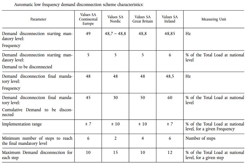
5.1. Automatic under-frequency control scheme .............................................................. 34
5.1.1. Automatic Low Frequency Demand Disconnection ........................................... 34
5.1.2. Management of Energy Storage Devices .......................................................... 36
5.2. Automatic Over-frequency control scheme ............................................................... 37
5.2.1. Over Frequency Generation Shedding (OFGS) Scheme .................................. 37
5.2.2. Step Wise Linear Disconnection ....................................................................... 37
5.3. Automatic Scheme against Voltage Collapse ........................................................... 38
5.3.1. Automatic under-voltage load shedding (UVLS)................................................ 38
5.4. Frequency Deviation Management Procedure .......................................................... 39
5.4.1. Demand Side Response ................................................................................... 40
5.4.2. Turlough Hill Pump Storage .............................................................................. 40
5.4.3. Active Power Set Points .................................................................................... 41
5.5. Voltage Deviation Management Procedure............................................................... 43
5.5.1. Reactive power set points ................................................................................. 43
5.6. Power Flow Management Procedure ........................................................................ 44
5.6.1. Active Power Set Points .................................................................................... 44
5.6.2. Special Protection Schemes ............................................................................. 44
5.7. Assistance for Active Power Procedure .................................................................... 46
Emergency and Restoration – SDP for Ireland
Page 35.7.1. Assistance for active power from SGU .............................................................. 46
5.7.2. East West Interconnector (EWIC) ..................................................................... 46
5.8. Manual Demand Disconnection Procedure ............................................................... 48
6. Next Steps................................................................................................................... 51
Appendix .............................................................................. Error! Bookmark not defined.
6.1.1. Definitions ............................................................ Error! Bookmark not defined.
Emergency and Restoration – SDP for Ireland
Page 4Emergency and Restoration – Response
Proforma
EirGrid invites responses to this consultation by 7 August 2020. The responses to the
specific consultation questions (below) or any other aspect of this consultation can be
provided by completing the following form. The form is also available in .doc format at
the Electricity Emergency and Restoration consultation section of our website.
Please return the completed form to gridcode@eirgrid.com
Respondent:
Company Name:
Does this response contain
confidential information? If
yes, please specify.
Name of Consultation this
response is in relation to:
No Question Response Rationale
(Y/N)
Do you agree with the
approach taken in the
1 proposal?
please provide rationale
Do you agree that the
proposal is consistent with
2 the principle of minimum
necessary change?
please provide rationale
Do you have any other
3 comments in relation to the
proposal?
Emergency and Restoration – SDP for Ireland
Page 51. Abbreviations
BASA – Balancing and Ancillary Services Agreement
BMPS – Balancing Market Principles Statement
CDGU – Centrally Dispatched Generation Unit
CRU – Commission for the Regulation of Utilities
DCC – Demand Connection Code
DSO – Distribution System Operator
EA – Emergency Assistance
EAS – European Awareness System
EMS – Energy Monitoring System
EWIC – East-West Interconnector
FCR – Frequency Containment Reserve
FRR – Frequency Restoration Reserve
FSM – Frequency Sensitive Mode
GC – Grid Code
HVDC – High Voltage Direct Current
LFCAOA - Load Frequency Control Area Operational Agreement
LFCBOA - Load Frequency Control Block Operational Arrangement
LFDD – Low Frequency Demand Disconnection
LFSM- Limited Frequency Sensitive Mode
MEC – Maximum Export Capacity
MVAr – Mega Volt-Ampere reactive
NCER – Network Code for Emergency Restoration
NCC – National Control Centre
OFGS – Over Frequency Generation Shedding
OSS - Operating Security Standards
PLC - Programmable Logic Controller
POR – Primary Operating Reserve
PPM – Power Park Module
RfG – Requirements for Generators
RTC – Real Time Commitment
RTD – Real Time Dispatch
RR – Replacement Reserve
Emergency and Restoration – SDP for Ireland
Page 6 SAOA – Synchronous Area Operational Agreement
SCADA - Supervisory Control and Data Acquisition
SDP – System Defence Plan
SGU - Significant Grid User
SOGL – System Operator Guideline
SONI - System Operator Northern Ireland
SOR – Secondary Operating Reserve
SRP – System Restoration Plan
SVC – Static Variable Compensator
TOR – Tertiary Operating Reserve
TSO – Transmission System Operation
UF – Under Frequency
UV – Under Voltage
UVLS – Under Voltage Load Shedding
WSAT - Wind Stability Assessment Tool
Emergency and Restoration – SDP for Ireland
Page 72. Purpose
This System Defence Plan (SDP) is prepared in accordance with COMMISSION
REGULATION (EU) 2017/2196 of 24 November 2017 “establishing a network code on
electricity emergency and restoration”1 (referred to as NCER), which came into force on
the 18th of December 2017. Under NCER the Transmission System Operators (TSO) of
a member state is required to develop and consult on a SDP prior to submission to the
relevant regulatory authority for notification. This is a revised version of the SDP
following a previous submission to the Commission for Regulation of Utilities (CRU).
This SDP has been designed based on the requirements detailed within Articles 11 to 22
within NCER, the high-level requirements of these articles include:
Design of the SDP
Implementation of the SDP
Activation of the SDP
Measures of the SDP
In addition to the SDP providing an overview of the power system defence actions and
schemes available to EirGrid as the TSO and the Distribution System Operator (DSO); it
also outlines the roles and responsibilities of Significant Grid Users (SGUs) including
defence service providers during the implementation of the SDP.
This document also outlines how the system defence measures and procedures that are
implemented within the EirGrid TSO controlled area of Ireland relate to the relevant
articles of NCER and the Grid Code2, whilst providing the reader with an:
Introduction to the system states of the power system
Introduction to power system operation
Overview of the system defence services
Understanding of the roles and responsibilities of specific parties
This is not an operational document to be used by the TSO in the event an Emergency
state being declared. The step by step actions used by EirGrid National Control Centre
(NCC) are included in real-time operational procedures. While the NCER requirements
and licence requirements for system defence are jurisdictional the aim is to ensure the
all-island system is maintained in a secure manner, hence there is a separate but
complementary Northern Ireland SDP which SONI has developed.
1
https://eur-lex.europa.eu/legal-content/EN/TXT/PDF/?uri=CELEX:32017R2196&from=en
2
http://www.eirgridgroup.com/site-files/library/EirGrid/Grid-Code.pdf
Emergency and Restoration – SDP for Ireland
Page 83. Introduction
There are various statutory obligations to which a TSO must adhere from European
directives, through to the applicable codes. The hierarchy order is demonstrated in
Figure 1 below.
Figure 1 – Hierarchy of Regulations
NCER is one of a suite of European Network Codes and Guidelines that seek to achieve
a fully functioning and interconnected energy market to ensure the security of supply and
to benefit all consumers via competitive markets across the EU.
The NCER aims to establish a set of common minimum requirements and principles for
the measures and procedures of TSOs, DSOs and SGUs when a power system is in
Emergency, Blackout or Restoration state, however, this SDP concentrates on operating
the power system when in Emergency state. There is a separate companion document,
the System Restoration Plan (SRP) detailing the TSO response to a Blackout state.
Emergency and Restoration – SDP for Ireland
Page 9The NCER links and interacts with a number of other Network Codes, including but not
limited to:
System Operation Guideline (SOGL), EU Regulation 2017/14853
Requirements for Generators (RfG), EU Regulation 2016/6314
High Voltage Direct Current (HVDC), EU regulation 2016/14475
Demand Connection Code (DCC), EU Regulation 2016/13886
From Figure 1, EU Regulations supersede national legislation and have primacy over
national and other regulations. Specifically, the design of this SDP is compiled in
accordance with NCER Article 11 and is consulted upon in accordance with Article 7.
The SDP includes a list of measures to help prevent the emergency event moving
towards a full or partial blackout. By identifying the relevant SGUs responsible for the
implementation of measures related to the SDP, known as defence service providers, a
mapping table of the SGU category groups, e.g. types of generators, demand,
Interconnectors or aggregators, listed against the relevant measure is provided for
transparency.
The SDP provides useful background information into how the TSO and DSO operate
the system during an Emergency state in order to return to Normal state as soon as
practicable. In order to place the SDP in an operational context, there is a description in
section 3 on how the TSO and DSO operate the system in the Normal and Alert states.
This design of a SDP also provides an overview of how the system defence measures
as specified in NCER will be satisfied, including by reference to existing codes.
The first version of the SDP proposal was consulted on from the 14th November 2018 to
12th December 2018 and received no responses. On 18th December 2018, EirGrid
submitted the following proposals relating to the SDP to the Commission for Regulation
of Utilities (CRU):
a) Terms and conditions to act as a defence service provider
b) List of Significant grid users Ireland (the TSO stated there are no High priority
grid users so did not provide a list)
c) Design of the System Defence Plan
Documents a) and b) are required to be approved by the CRU while the design of the
SDP is only required to be notified to the CRU. However, the SDP strongly interacts with
the NCER documents that do require approval and should be considered together as a
3
https://eur-lex.europa.eu/legal-content/EN/TXT/PDF/?uri=CELEX:32016R1388&from=EN
4
https://eur-lex.europa.eu/legal-content/EN/TXT/PDF/?uri=CELEX:32016R0631&from=EN
5
https://eur-lex.europa.eu/legal-content/EN/TXT/PDF/?uri=CELEX:32016R1447&from=EN
6
https://eur-lex.europa.eu/legal-content/EN/TXT/PDF/?uri=CELEX:32016R1388&from=EN
Emergency and Restoration – SDP for Ireland
Page 10package. On the 2nd September 2019, the CRU published a decision to not approve
documents a) and b) above and seek amendments to all the documents submitted by
EirGrid. While the Design of the SDP is not subject to formal approval, the CRU provided
informal comments, as the CRU noted that the SDP is critically important to system
operation and appropriate procurement of defence service providers. In addition to
meeting the SDP requirements as stipulated in NCER, this document has close regard
for CRU feedback in this revised SDP. Additionally, the document has been updated in
collaboration with the DSO.
The following public documents, which have arisen from the requirements of SOGL also
relate to NCER. All, except the Operating Security Standards, had not been written at
the time of the original submission to the CRU and are now of relevance to this
resubmission proposal.
Synchronous Area Operational Agreement (SAOA)7
Load Frequency Control Block Operational Arrangement (LFCBOA)8
Load Frequency Control Area Operational Agreement (LFCAOA)9
Business Procedure mapping SOGL System states10
Operating Security Standards (OSS)11
7
http://www.eirgridgroup.com/site-files/library/EirGrid/SAOA-for-the-Ireland-and-Northern-Ireland-Synchronous-area-V2.0-(for-
consultation-post-RfA).pdf
8
http://www.eirgridgroup.com/site-files/library/EirGrid/S2-LFC-Block-Operational-Agreement-for-Ireland-and-Northern-Ireland-16.12.2019-
(post-Title-2-approval).pdf
9
http://www.eirgridgroup.com/site-files/library/EirGrid/S3-LFC-Area-Operational-Agreement-for-Ireland-and-Northern-Ireland-
16.12.2019.pdf
10
https://www.sem-o.com/documents/general-publications/BP_SO_09.2-Declaration-of-System-Alerts.pdf
11
http://www.eirgridgroup.com/site-files/library/EirGrid/Operating-Security-Standards-December-2011.pdf
Emergency and Restoration – SDP for Ireland
Page 113.1. Introduction to System States
The TSO is required to monitor and communicate the state of Ireland’s transmission
systems. The SOGL defines the following five system states (demonstrated in
Figure 2, contained within the red dashed line) and provides a set of criteria for each
system state. These system states have been aligned with the existing system alerts in
an all-island business process which describes how the system alerts states are defined
and declared, BP_SO_9.212 refers:
12
https://www.sem-o.com/publications/tso-responsibilities/
Emergency and Restoration – SDP for Ireland
Page 12SOGL Existing
System System
States Alerts
Figure 2 – SOGL aligned System States and Alerts
The system states range from the Normal state to increasing levels of system stress;
Alert state (Amber alert); Emergency state (Red Alert); Blackout state (Blue Alert)>
There is also a Restoration state during which actions are being taken to bring the power
system back to the Normal state.
In accordance with the NCER, the SDP describes the management of the system during
the Emergency state or if it is about to enter the Emergency state; therefore to fully
explore the system operation during an Emergency state, consideration is given in this
SDP to explaining system operation during both Normal and Alert states.
For operation during a Blackout state please refer to the separate companion document
the SRP, which is also produced by EirGrid in accordance with NCER.
The classification of transmission system states is prescribed in SOGL article 18 and
specifically for EirGrid’s transmission system is laid out in BP_SO_9.213, which considers
the transmission system to be in Emergency state (Red Alert) if any of the following has
occurred:
13
https://www.sem-o.com/publications/tso-responsibilities/
Emergency and Restoration – SDP for Ireland
Page 13a) there is at least one violation of voltage limits, short-circuit current limits, or
current limits in terms of thermal rating;
b) frequency does not meet the criteria for the Normal state or Alert state;
c) any of the following system defence plan measures are activated;
1. Activation of Under Frequency (UF) load shedding,
2. Widespread (multiple station) Under Voltage (UV) load shedding,
3. Activation of system separation protection.
4. Activation of Emergency Assistance / Emergency Instruction
d) there is a failure in the functioning of
1. EMS/ SCADA
2. Phones (Corporate and Optel)
resulting in the unavailability of those tools, means and facilities for longer
than 30 minutes.
The "Red Alert" signal should also be initiated by the TSO when it is likely/ imminent that
in the period immediately ahead (i.e. in the next 4 hours) there is a high risk of failing to
meet System Demand.
When an Emergency state occurs a Red Alert is issued from the TSO notifying all
generating stations, designated transmission stations, DSO, relevant TSO Staff and key
external stakeholders. The TSO will also update the European Awareness System
(EAS), which notifies other European TSOs that EirGrid is in Emergency state. Once a
measure or measures in the SDP have been activated the EAS is updated to
Restoration state. Once the system has over an hour of stable operation with a low risk
of further alerts, then the Red Alert is cancelled and the TSO updates the EAS to Normal
state.
3.2. Generic Power System Operation Overview
Managing a synchronised power system is a complex job and requires co-ordination and
co-operation between TSOs, DSOs, generators and demand service providers. While
the definition of the three system states Normal, Alert and Emergency are relatively
clear, the actions of the TSO are not so distinct. It should be noted that the transition
from Normal/Alert state to Emergency state does not convey additional powers on the
TSO; the main aim of the TSO remains the same, i.e. to operate, or if necessary restore
the system within the operational limits (Normal state).
To maintain the system within operational limits requires constant vigilance; using
forecasts and reviewing real-time data to inform the next TSO action to be taken. Due to
the small size of the synchronous power island there are relatively many more balancing
Emergency and Restoration – SDP for Ireland
Page 14actions to be instructed in comparison to the central EU synchronous system. A prudent
TSO does not hold back in taking an action, such as waiting until the system is in
Emergency state would be too late and at odds with the TSO’s legal mandate. There
are, however, some automatic system defence measures described in this SDP to
prevent fast acting phenomena.
Therefore, this SDP includes an explanation how the TSO manages within normal
operational limits, as some of these measures which are used in Normal and Alert state
are still active and continuing if the system fails to recover and transitions to Emergency
state.
This SDP will provide a comprehensive overview of how the TSO manages the system
against the main events that impact the operation of a synchronous electrical system
together with the actions available to the TSO. Where the action is only applied during
the defined Emergency state, and hence is a system defence measure, this will be
highlighted.
3.3. Operational Limits
There are many variables in a complex synchronous electrical system and the TSO
operates within certain limits to ensure standards are maintained. These limits are
defined in SOGL and will be enacted in the Operational Security Standards (OSS), which
is currently under review to ensure they align with the requirements of the SOGL.
The transmission system is operated so that under normal operation and in the event of
certain anticipated contingencies (loss of any single item of generation or transmission
plant (N-G, or N-1) there will be no:
Loss of supply, subject to certain exceptions, see below
Frequency event outside the operational limits
Voltage conditions outside the operational limits
Transmission plant operating outside its short term rating
System instability
A brief discussion of each of these issues is provided below.
3.3.1. Loss of supply
The transmission system is designed with certain amount of redundancy of plant, e.g.
double overhead line circuits and more than a single transformer at a substation. This is
to ensure maintenance of an individual item is possible without a subsequent loss of
supply. In addition, credible contingencies (fault or forced outages) may be covered
Emergency and Restoration – SDP for Ireland
Page 15during planned scheduled maintenance. Therefore, no loss of supply is allowed for a
single contingency / maintenance outage, however, a fault during a maintenance outage
can lead to a load of up to 80MW to be lost, see OSS for details.
3.3.2. System Frequency
Frequency is a measure of the transmission system being in balance, i.e. when the
amount of generation dispatched equals the amount of demand on the system then
frequency is exactly 50Hz across the whole synchronous area. Minute by minute
variations on the system means that frequency varies from the nominal 50Hz, e.g. an
excess of generation and the frequency rises above 50Hz. Therefore, an operating
range around 50Hz defines the frequency quality parameters which apply to EirGrid/
SONI synchronous area.
standard frequency range ± 200 mHz
maximum instantaneous frequency deviation 1000 mHz
maximum steady-state frequency deviation 500 mHz
time to recover frequency 1 minute
frequency recovery range ± 500 mHz
time to restore frequency 15 minutes
frequency restoration range ± 200 mHz
alert state trigger time 10 minutes
Table 1 – SOGL Frequency Parameters
Table 1 shows the SOGL defined quality parameters copied from SAOA. The following
graphic, Figure 3, summarises when an alert would be triggered based on a deviation
from 50Hz for steady state situations (> 1 minute). For clarity, the graphic does show a
short duration transient state for one minute where the frequency could fall to 49.0Hz
and recover to 49.5Hz and the system remains in Normal state.
Emergency and Restoration – SDP for Ireland
Page 1651.1
51.0
50.9
50.8
50.7
50.6
50.5
50.4
50.3
50.2
Frequency (Hz)
50.1 Max Instantaneous Max Steady State
50.0 Frequency Deviation Frequency Deviation Standard Frequency
49.9
± 1000 mHz ± 500 mHz Range ± 200 mHz
Normal
49.8
49.7
49.6 Alert
49.5
49.4 Emergency
Time to Recover
49.3
Frequency (1 min)
49.2
49.1 Start of Steady Alert State Time to Restore
49.0 State Timeframe Trigger Time Frequency
48.9
-1 0 5 10 15 20 25
Duration of Steady State Frequency Deviation (Minutes)
Figure 3 – System States during a Frequency Transient3.3.3. Voltage
Voltage can be used as an indicator of the health of a transmission system. There are
various levels of nominal voltage used in the EirGrid transmission system, 400kV, 220kV
and 110kV, plus 275kV on the tie-line to SONI. For efficiency, the higher voltages are
used for transmission purposes and the voltage is incrementally stepped down for the
DSO to distribute to consumers at lower voltages. Transmission plant is designed to
operate at a range centred on the nominal voltage and SOGL provides the following
limits (Table 2) for an intact system (Base Case) and for the credible contingencies
mentioned above. Voltage issues are more likely to manifest in a localised areas of the
transmission system due to individual faults, however, widespread voltage collapse is
possible if reactive power (MVAr) reserves are severely depleted.
Nominal Voltage Base Case and Contingency Limits
(kV)
400kV 360 - 420
275kV 248 - 307
220kV 198 - 246
110kV 99 - 123
Table 2 - SOGL Voltage Limits
3.3.4. Power Flows
The fundamental objective of a transmission system is to transport electricity from the
generation source to the demand centres. All plant and equipment that carries electricity
have a thermal limit beyond which it will fail to operate safely; therefore it is the
responsibility of the TSO to ensure the transmission system is operated within the
thermal limits. However, during system disturbances, such as immediately post-fault, a
temporary overload rating may apply where the rating may exceed 100% of the normal
(pre-fault) rating. Depending on the type of plant this temporary rating may apply for a
maximum of a few minutes to a couple of hours and allows the TSO time to recover the
system to within normal ratings.
3.3.5. System Instability
Instability of a power system could cover numerous scenarios including voltage and
frequency issues mentioned above. However, with the changing nature of generation
towards more renewable sources the system inertia (a measure of how robust the
system is to disturbances) is reducing and has to be monitored closely. There has been
detailed offline analysis carried out to provide certain constraints to manage inertia, e.g.
Emergency and Restoration – SDP for Ireland
Page 18there is a percentage limit on the System Non-Synchronous (generation) Penetration
(SNSP) figure and there are a certain number of synchronous machine units constrained
to run to ensure the system inertia remains above a minimum level. These constraints
and others are published monthly in the Operational Constraints Update14 and are used
in the online transient stability assessment tool.
3.4. Operation of a Power System by EirGrid
As discussed in the Balancing Market Principles Statement (BMPS), the main objectives
of EirGrid, as TSO, in operating the power system are to:
1. Ensure operational security
2. Maximise renewable sources
3. Provide efficient operation of the market
The requirement to provide transparency is an overarching obligation and EirGrid
supports the transparency objective through the design of our processes and tools
including a range of publications, such as the BMPS which describes the Scheduling and
Dispatch process summarised below in greater detail.
Starting in the longer term (in outage planning timescales), offline analysis is carried out
to calculate the operating reserve requirements and system constraints which are
published monthly in the Operational Constraints Update. Still in outage planning
timescales but nearer real-time there is a Weekly Operational Constraints Update
published based on offline studies with the forecast system outages. This is to provide
information on any forecasted significant network congestion or other issues that could
potentially restrict dispatchable generation in a particular area or to flag if dispatchable
generation is required in a particular area.
All these constraints are fed into EirGrid’s scheduling tool which is looking up to 30 hours
ahead of real-time using the currently connected generation technical data and wind
forecasts. This produces a secured schedule for each half-hour for the following day that
meets the demand forecast and satisfies the constraints (incl. reserve) delivered in the
most efficient and economical way.
This secured schedule is refined approximately every 4 hours on the actual day. Then at
4 hours ahead there is the RTC schedule (Real Time Commitment on units to be
dispatched) refined every 15 minutes followed at one hour ahead by the RTD schedule
(Real Time Dispatch showing indicative units to increase or decrease) refined every 5
minutes.
14
http://www.eirgridgroup.com/library/index.xml, filter on Operations then Constraints Update.
Emergency and Restoration – SDP for Ireland
Page 19While the above schedules are created using the indicative demand and generation
patterns, the TSO uses the EMS (Energy Management System) to provide real-time
indication and control of the power system, which includes a SCADA (Supervisory
Control and Data Acquisition) system for gathering real-time data from the power system.
This runs a full contingency analysis every minute to flag up any predicted violations of
voltage or thermal limits.
Also in real-time, the WSAT (Wind Stability Assessment Tool) runs every 5 minutes
testing the transient stability of the system on all defined contingencies. The output is a
prediction of the frequency nadir and the likely rate of change of frequency for each
credible event. Real-time information is provided to the operators as alarms when any
limit is approached so that manual actions may be taken as necessary.
3.4.1. Frequency Management
The system frequency is monitored on a second by second basis by the TSO. Through a
combination of frequency regulation from various responsive plant and dispatch of
generating units to change their output level, frequency is maintained within the
Standard Frequency range (see Table 1) under normal system conditions.
Frequency regulation is managed through the provision of different types of reserve
products described in SOGL. The SAOA maps the existing Grid Code reserve products
(Primary, Secondary and Tertiary Operating Reserve – POR, SOR, TOR) to the SOGL
categories, see below. For all reserve providers, the reserve capability is mandated by
the Grid Code and contracted via System Services agreements. These measures to
control frequency are available for the TSO to select the most economic service
providers.
While there are commercial services available to the TSO, such as Fast Frequency
Response, this discussion is concentrating on the SOGL defined reserve services.
Therefore, the initial response to managing the frequency is provided by Frequency
Containment Reserves (FCR) (previously POR & SOR) which acts within 90 seconds.
Frequency Restoration Reserves (FRR) (previously TOR) is fully available after 90
seconds and is sustainable for up to 20 minutes.
Sufficient FCR and FRR are held to ensure that for the loss of the largest single power
infeed to / or outfeed from the system at any time, the system frequency (See also
Figure 3 – System States during a Frequency Transient):
deviation does not exceed the Maximum Instantaneous Frequency Deviation of
1000 mHz and returns to within the Maximum Steady State Frequency Deviation
within 1 minute
Emergency and Restoration – SDP for Ireland
Page 20 deviation does not exceed the Maximum Steady State Frequency Deviation (+/-
500 mHz) after 1 minute and returns to the Standard Frequency Range within 15
minutes
deviation remains within the Standard Frequency range (50 +/- 200 mHz) after 15
minutes with a quality target outside this range limited to a maximum 15,000
minutes annually for all conditions
To ensure there are sufficient frequency response services ahead of real-time, these
requirements are included in the scheduling tools calculating each half-hour scheduling
period from 30 hours ahead based on the largest infeed loss for that interval. Together
with other variables such as demand characteristics, technical and commercial data a
co-optimisation of system services is scheduled to ensure reserve requirements are
always met economically and efficiently.
Following any frequency incident where reserves have been depleted, such as an
unexpected loss of a large generator, Replacement Reserve (RR) will be dispatched to
recover the operating reserve within 20 minutes and is sustainable for up to 4 hours to
cover for the next contingency.
The East West Interconnector (EWIC) link to Great Britain can provide a low and high
frequency response service to both power systems. For low frequency events in Ireland
EWIC can provide response using its Frequency Control – Sensitive Mode (FC-SM).
Once system frequency reaches 49.80Hz, EWIC will start providing response at a rate of
500MW/Hz up to the maximum agreed MW value at a frequency of 49.65Hz. The
maximum MW value is currently 75MW. The response will be maintained below the
lower frequency value and once the frequency rises above 49.65Hz the response will
begin decreasing (at 500MW/Hz) until reaching 49.80Hz when the response will have
reduced to zero. Depending on the frequency deviation and the duration of the response,
it is classed as FCR or FRR.
For a high frequency in Ireland, once system frequency reaches 50.20Hz, EWIC will start
providing response with at a rate of 500MW/Hz up to the maximum agreed MW value at
a frequency of 50.35Hz. The maximum MW value is currently 75MW. The response will
be maintained above the higher frequency value and once the frequency falls below
50.35Hz the response will begin decreasing (at 500MW/Hz) until reaching 50.20Hz when
the response will have reduced to zero. Depending on the frequency deviation and the
duration of the response, it is classed as FCR or FRR.
In accordance with SOGL and applied in the Grid Code all Interconnectors must remain
connected to the transmission system and operational between 47.0 Hz up to 52.0Hz
(below 47.5Hz they only need to stay operational for 30 seconds).
Should the frequency fall unexpectedly outside the Maximum Steady State Frequency
Deviation limits then automatic under/over frequency control schemes and/or Low
Frequency Demand Disconnection schemes operate, see sections 5.1 and 5.2.
Emergency and Restoration – SDP for Ireland
Page 213.4.2. Voltage Management
The correct control of the system voltage is fundamental to the safe and secure
operation of the power system. The TSO is obliged to operate the transmission system
with the operational security limits defined in SOGL, see Table 2.
However, EirGrid has a more stringent set of voltage limits in operational timescales, the
Normal System Voltage range:
Nominal Voltage Base Case Limits (kV) Post Contingency Limits (kV)
400kV 395 - 410 360 - 420
275kV 275 - 285 250 - 303
220kV 225 - 238 200 - 242
110kV 110 - 118 99 - 121
Table 3 - Irelands Voltage Limits
Managing the system to a tighter range around the nominal voltage helps to ensure the
long-term system security and integrity of plant.
Assessments are carried out in Long Term Planning timescales to identify certain “must
run” generation units due to voltage constraints in localised areas. This analysis is
carried out on an offline study. In real time there is an online contingency analysis testing
each contingency in turn which is updated using latest wind forecasts and real time data,
in order to take pre-emptive action to avoid a post fault breach of the voltage limits. This
real time analysis takes place continuously.
The voltage management of the system is achieved in a number of ways and the options
available to engineers in operational timescales are:
switching reactive compensation equipment
o Capacitors
o Reactors
Instructing MVAr on synchronous generation
Changing target voltage set points
o Static Variable Compensators (SVCs)
o Power Park Modules (PPM)
Switching out high reactive gain circuits
Simultaneous tap changing of NCC controlled grid transformers
Tap staggering of parallel NCC controlled system transformers
These measures are all designed to ensure the system remains within the Normal
System voltage range with sufficient voltage support (MVAr) reserves to limit the voltage
step change post contingency within the post-contingency limits and hence avoid an
Emergency state. Specifically for voltage issues, an Emergency state is when at least
Emergency and Restoration – SDP for Ireland
Page 22one violation of voltage limits is active and or widespread (multiple) under voltage load
shedding activated.
3.4.3. Power Flow Management
Power flows across the synchronous area of Ireland are managed by the TSOs. In
accordance with the Balancing Market Principles Statement, system constraints are one
of the inputs into the optimisation tools so that transmission plant outages are taken into
account. The objective is to ensure that the system is operated within the thermal limits
of the transmission equipment.
Standard remedial actions to maintain the system in Normal State include:
Re-switching circuits to restrict flows
Return of outage plant to remove system overload
Re-dispatch active power set points for generators online
Schedule additional generation
Tap change of transformers
Adjust active power flows through HVDC systems with other TSOs
Under fault conditions temporary (emergency) load conditions may be applied to
equipment as system conditions dictate. If a severe overload is anticipated for a post-
fault condition automatic protection schemes may be used to preserve the integrity of the
transmission plant and apparatus.
These measures are all designed to ensure the system remains within the standard pre
and post contingency operating capability and hence avoid entering an Emergency state.
Specifically as regards thermal issues, an Emergency state is when at least one violation
of current limits on transmission plant is active, or activation of system separation
protection.
Emergency and Restoration – SDP for Ireland
Page 234. Design of the System Defence Plan
4.1. Objectives of the SDP
The SDP is designed to conform to the NCER Articles 11 to 22 and it is intended to
serve as an oversight document referencing the more detailed plans. Should the detailed
plans change to take into account the characteristics of the transmission system or
underlying DSO systems, due to the behaviour and capabilities of load and generation
within the synchronous area, then changes would be made in accordance with the
NCER.
As referenced in NCER Article 11(5), the SDP contains the following technical and
organisational measures:
System protection schemes (automatically initiated) including:
automatic under-frequency control scheme
automatic over-frequency control scheme
automatic scheme against voltage collapse
System defence plan procedures (manually instructed) including:
frequency deviation management procedure
voltage deviation management procedure
power flow management procedure
assistance for active power procedure
manual demand disconnection procedure
Some of the above measures may be provided by neighbouring TSOs and while TSO
assistance is not in the group of measures listed in the NCER Article 11(5), Inter-TSO
assistance and co-ordination in an Emergency state is prescribed in NCER Article 14 to
ensure consistency of co-operation across the EU TSOs.
In developing the SDP measures, which may be provided by designated SGUs, EirGrid
has co-ordinated and consulted with the DSO on the production of this document to
ensure the following NCER principles are met:
the impact of the measures on the system users shall be minimal
the measures shall be economically efficient
only those measures that are necessary shall be activated
the measures shall not lead the TSO's transmission system or the interconnected
transmission systems into Emergency state or Blackout state.
Emergency and Restoration – SDP for Ireland
Page 24NCER Article 11(3) lists the following provisions that the SDP must contain:
a) The conditions under which the SDP is activated;
b) The SDP instructions to be issued by the TSO; and
c) The measure subject to real-time consultation or coordination with the identified
parties.
For a) please see next section for a detailed explanation, whereas b) and c) may be
described more generally. The system defence measures discussed in this section and
described in greater detail in section 5 are all existing measures currently available to the
TSO, and there are well established communication channels and relevant procedures.
This is the case for all SGUs and the DSO.
All automatic control schemes are activated when the relevant threshold is reached and
instructions or real-time consultation is not possible, whereas for the manual procedures
a significant majority of the procedures is the TSO directing the defence service
providers, usually via dispatch instructions, or the DSO via control room telephony.
Where a manual procedure is initiated by instruction from the TSO this is highlighted in
the section description of the measure.
4.2. Activating the SDP
The SDP contains (manual) procedures and automatic schemes available to the TSO to
prevent the further deterioration towards an Emergency state when one is forecast or to
manage the system when it is in an Emergency state.
The NCER states, as per below, that system defence measures can be activated once
the system is in Emergency state or, alongside remedial actions based on operational
security analysis, to prevent the system from entering the Emergency state.
NCER Article 13 (2) states, in addition to the automatically activated schemes of the
system defence plan, pursuant to point (a) of Article 11(5), each TSO shall activate a
procedure of the system defence plan when:
(a) the system is in emergency state in accordance with the criteria set out in
Article 18(3) of Regulation (EU) 2017/1485 and there are no remedial actions
available to restore the system to the normal state; or
(b) based on the operational security analysis, the operational security of the
transmission system requires the activation of a measure of the system defence
plan pursuant to Article 11(5) in addition to the available remedial actions.
Emergency and Restoration – SDP for Ireland
Page 25Each TSO uses ‘remedial actions’ to prevent their system from deteriorating and
transitioning away from the Normal system state. These actions are categorised in
SOGL (Article 22 refers) in general terms and some have been described in section 3.4
above. NCER re-classifies these actions as system defence measures when these
actions are included in the system defence plan.
As noted in the previous section NCER divides system defence measures into automatic
schemes and manual procedures, therefore automatic schemes in the SDP may be
described as:
those initiated when the trigger threshold for each particular scheme is
reached, e.g. low frequency relay, and when system is in Emergency state.
Manual procedures in the SDP may be described as:
those that are instructed when the system is in Emergency state when there
are no remedial actions available (NCER 13 (2) (a)), or
those that are instructed based on a forecast that the system will enter an
Emergency state even with available remedial actions being activated (NCER
13 (2) (b))
Consideration is given below to the differences between remedial actions and manual
procedures in the SDP.
The TSO has various actions available to correct various phenomena (frequency or
voltage or power flows outside relevant operational limits) whereby some remedial
actions and system defence procedures may require similar actions. It is important to
note that the differentiation can be attributed to the status of the system when the
measure is applied.
Remedial actions are applied first within Normal/Alert state and if these remedial actions
are no longer effective in either;
a timed capacity (not fast acting enough to stop the system entering Emergency
state), or
a resource capacity (not adequate to stop the system entering Emergency state),
then
the SDP is activated and the resulting actions are system defence procedures.
In summary a system defence measure may be described as either:
• An automatic or manual corrective action initiated / instructed during an
Emergency state, or
• A manual corrective action, designed to be used during an Emergency state,
instructed when an Emergency state is forecast.
Emergency and Restoration – SDP for Ireland
Page 26A mapping table has been provided in Table 4 below to show which actions are part of
the SDP and which are categorised as remedial actions. Note that some actions may be
initiated manually during the Normal and Alert state and may be thought as a remedial
action; however, they are a system defence procedure if the system is expected to
transition into the Emergency state. This is typical of the transient nature of events
impacting on the transmission system.
Table 4 contains the automatic scheme or manual procedure discussed above in
chronological order of NCER Articles and colour coded on the left hand side of the table.
By identifying all the actions available to the TSO in each category it is categorised
against a remedial action or system defence measure as defined above. Again it is
X
colour-coded for ease, with red filled boxes , , denoting a system defence
X
measure; a blue filled boxes denoting a remedial action and green filled boxes,
X
denoting an action that could be a remedial action or a system defence
measure depending when the action was initiated. All the actions identified as system
defence measure are discussed in detail in chapter 5.
Emergency and Restoration – SDP for Ireland
Page 27Table 4 – Mapping Table - Remedial Actions Vs System Defence Measures
System
NCER Chapter II Section 2 Technical & Control Scheme / Remedial
Article Defence Reasoning
Organisational Measures Management Procedure Action
Measure
LFDD X Low Frequency Relays triggered from 48.85Hz
15
Automatic Under Frequency Control Schemes
Energy Storage Providers (X) Currently none available, however, proposed frequency threshold is 49.0Hz
System Protection Schemes
OFGS X High Frequency Relay triggered from 50.50Hz
16
Automatic Over-Frequency Control Schemes
Step wise linear disconnection X Triggered from Frequency Threshold of 50.5Hz
UVLS (Low voltage Demand disconnection) X Scheme triggered when local voltage is below voltage standards
17
Automatic Scheme Against Voltage Collapse
Automatic Blocking Auto-tap transformers scheme Confirmed that automatic scheme is not required.
Standard Frequency Management Actions X Remedial Actions as taken in Normal / Alert state
Operating Reserve - FCR X
Remedial Action as FCR is as initiated within 15 seconds of frequency deviation
FRR may be Remedial Action or System Defence Measure depending on system state when initiated
Operating Reserve - FRR X X
(15s - 90s)
RR may be Remedial Action or System Defence Measure depending on system state when initiated
Operating Reserve - RR X X
(20mins)
LFSM-U is designed to be initiated at 49.5Hz, however, policy for it to start at 49.8Hz to be consistent
Limited Frequency Sensitive Mode - Under X
with Non-RfG PPMs. Therefore a Remedial Action.
18
Frequency Deviation Management Procedure Limited Frequency Sensitive Mode - Over X LFSM -O is Remedial Action as initiated at 50.20Hz
Frequency Control - Sensitive Mode is a Remedial Action as initiated at 49.80Hz (Low) or 50.20Hz
East West Interconnector X
(High).
For Low Freq. Remedial Action if initiated in turbine mode & System Defence Measure if initiated in
Turlough Hill pump storage X X
pump mode. For High Freq. System Defence Measure as trips at 51.50Hz
Active power set points within technical parameters when Frequency is Generators and DSUs dispatched centrally even if Frequency is outside Alert Limits. Therefore a
X
outside Alert Limits. System Defence Measure.
System Defence Plan Procedures
Low Freq.: System Defence Measure as possible if below 49.50Hz and above 48.85Hz (LFDD threshold),
Authority to disconnect SGUs X
see manual demand disconnection. High Freq.: Rare to be a System Defence Measure as above
Energy Storage Providers (X)
ESS: Before LFDD triggered: change load to Gen mode or trip load? Currently none available.
Standard Voltage Management Actions X Remedial Actions as taken in Normal / Alert state
Authority to establish reactive power set-points & running additional Generators and DSUs dispatched centrally even if outside operational security Limits. Therefore a
19
Voltage Deviation Management Procedure X
generation for MVars System Defence Measure.
System Defence Measure as requesting Emergency Assistance for reactive power from TSOs not in
Other TSO making MVars available X
Emergency state.
Standard Power Flow Management Actions X Remedial Actions as taken in Normal / Alert state
Generators and DSUs dispatched centrally even if outside operational security Limits. Therefore a
20
Power Flow Management Procedure Active power set points within technical parameters (Special Actions) X
System Defence Measure.
Disconnection of circuits to prevent excessive thermal overload outside operational limits. Therefore
Authority to disconnect SGUs inc. Special Protection Schemes (Thermal) X
System Defence Measure.
Generators and DSUs dispatched centrally even if system adequacy is lacking. Therefore a System
Balancing service provider X
Defence Measure.
21
Assistance for Active Power Procedure Non-Balancing service provider (non- available) (X) Currently none available.
System Defence Measure as requesting Emergency Assistance for active power from TSOs not in
East West Interconnector X
Emergency and Restoration – SDP for Ireland Emergency state.
Emergency load shedding (5min) Page 28 X Manual Action to avoid prolonging Emergency state (frequency deterioration, thermal overloads, and
under voltage). Therefore a System Defence Measure.
Manual Action to avoid prolonging Emergency state (frequency deterioration, thermal overloads, and
22
Manual Demand Disconnection Procedure Emergency load shedding (30mins) X
under voltage). Therefore a System Defence Measure.
Manual Action to avoid prolonging Emergency state (frequency deterioration, thermal overloads, and
Rota Load shedding X
under voltage). Therefore a System Defence Measure.4.3. Application of the SDP
As outlined in NCER Article 2, SGUs for this regulation include the following:
Generators from 5MW upwards (Type C , D)
Generators from 100kW to < 5MW (Type B) where these units are identified as
SGUs
transmission-connected demand facilities
transmission connected closed distribution systems
aggregators of re-dispatching of power generating modules or demand facilities
and providers of active power reserve
HVDC Interconnector Owners
For clarity, the tabular format and graph of the RfG generator types are presented in
Table 5 – Limits for thresholds for type B, C and D power-generating modulesbelow.
Table 5 – Limits for thresholds for type B, C and D power-generating modules
Emergency and Restoration – SDP for Ireland
Page 29Power Generating Module's Max Capacity (MW): 0 0.0008 0.1 1 2 3 4 5 6 7 8 9 10 …
Type A band A
Type B band
-allowed lower limit of band shown with dashed
arrow B
Connection -banding shown with a coloured blockNon-
SGUs
SGUs
T-Conn closed Distribution Systems
Type D Generator (D-Connected)
Type D Generator (T-Connected)
Aggregators of Gen/ Dem
DSO Demand Customers
T -Conn Demand Facility
Interconnector Owners
NCER Chapter II Section 2
NCER Individual System Defence Measure
Type B Generator
Technical & Organisational
Type C Generator
Article / Service
Measures
Automatic Under Frequency LFDD (Low Frequency Demand
15
Control Schemes Disconnection
X*
Over Frequency Generator
Shedding Scheme
X
Automatic Over-Frequency
16
Control Schemes
Step wise linear disconnection X X X X
Automatic Scheme Against UVLS (Low voltage Demand
17
Voltage Collapse disconnection)
X**
Operational Reserve (FRR) (Inc.
Turlough Hill)
X X X X X
Replacement Reserve (RR) X X X X X
Frequency Deviation
18
Management Procedure Active power set points when
Frequency is outside Alert Limits.
X X X X X
Authority to disconnect SGUs X X X X X X X
Reactive power set-points X
Voltage Deviation Management
19
Procedure
Other TSO's making Mvars available X
Active power set points when
power flow is outside Alert Limits.
X X X X X
Power Flow Management
20
Procedure
Special Protection Schemes X X X X
Active power set points when
system adequacy is lacking.
X X X X X
Assistance for Active Power
21
Procedure Interconnectors Emergency
Assistance (MWs)
X
Manual Demand Disconnection Emergency load shedding (inc. 5m ,
22
Procedure 10m & Rota)
X*
* Unless Exempted
** At locations
designated by the TSO
Table 6 - Mapping of SD Services against SGUs/ Non- SGUs
To simplify the mapping table, Table 7 has been provided to show the remaining system
defence measures provided by SGUs in order of the service provided by most SGUs.
Please note that some similar services from the same providers have been merged to
minimise this summary table. Table 7 will be taken forward in the complementary
document where Terms and Conditions for providing these services is discussed.
Emergency and Restoration – SDP for Ireland
Page 31SGUs
T-Conn closed Distribution Systems
Type D Generator (D-Connected)
Type D Generator (T-Connected)
Aggregators of Gen/ Dem
T -Conn Demand Facility
Interconnector Owners
Individual System Defence Measure / Service
Type B Generator
Type C Generator
Authority to disconnect SGUs X X X X X X X
Operational Reserve (FRR) (Inc. Turlough Hill) X X X X X
Replacement Reserve (RR) X X X X X
Active power set points when Freq./ Power Flow is
outside Alert limits and system adequacy is lacking
X X X X X
Special Protection Schemes (Inc. Step wise linear
diaconnection)
X X X X
Over Frequency Generator Shedding Scheme X
Reactive power set-points X
Interconnector Emergency Assistance (MWs) &
Making Mvars available
X
Table 7 - Simplified Mapping of System Defence services against SGUs
4.3.1. High Priority SGUs
In accordance with NCER, the TSO is to submit to the CRU for approval the list of High
Priority SGUs, which is defined as ‘the SGU for which special conditions apply for
disconnection and re-energisation’.
In the Grid Code Priority Customers is a defined term which refers to customer that are
excluded from Demand Control, GC OC.5.1.5 refers. Similarly, in the D-Code Demand
Control is exercised equitable between customers, however, exemptions may apply to
vital and priority customers as defined in the distribution load shedding plan, DOC5.1.4,
refers.
Emergency and Restoration – SDP for Ireland
Page 32You can also read