International Dragon Class - Effective date:2020-01-01v2 Status: Approved - Drachenklasse
←
→
Page content transcription
If your browser does not render page correctly, please read the page content below
Effective date:2020-01-01v2
Status: Approved

      International Dragon Class

 The International Dragon was designed in 1929 by Johan Anker.
Nominal Principal Dimensions

                                 LOA                                       8.9m
                                 Beam                                      1.95m
                                 Draft                                     1.2m
                                 Displacement                              1700kg (with mast)
                                 Mainsail                                  16m²
                                 Genoa                                     11.7m²
                                 Spinnaker                                 23.6m²

LIST OF OFFICIAL PLANS

A separate Appendix containing Rules concerning carvel construction and wooden spars is available from the World
Sailing.

Plan   Description                               Date of Plan    Date of Amendment/Issue number

1      Hull and Keel and Offsets                 March 1990      November 1994, April 1997, Feb 2001 (Issue 6)

2      Keel Sections and Detail of heel          March 1990      November 1994 (Issue 4)

3      Template Plan                             February 2001   (Issue A)

4      Construction plan - Wood                  March 1990      June 1991, Feb/Mar 1992, July/Nov 1994 (Issue
                                                                 5)

5      Construction plan - GRP                   March 1990      July/November 1994, March 2002 (Issue 6)

6      Sail and Rigging Plan                     March 1990      June 1991, Feb/Mar 1992, Nov 1994 (Issue 4)
                                                                 March 2002 (Issue 5), March 2005 (Issue 6)
                                                                 March 2009 (issue 7)

7      Finished Keel Templates (Full Size)       March 1997

8      Hull Offsets and Templates                February 1999   February 2001 (Issue C)
       (Full Size)

                                                         1
Table of Contents

NOMINAL PRINCIPAL DIMENSIONS ........................................................ 1
LIST OF OFFICIAL PLANS ........................................................................ 1
1.      GENERAL......................................................................................... 3
2.      HULL AND DECK ............................................................................. 6
3.      CABIN, COCKPIT AND HATCHES ................................................ 13
4.      BALLAST KEEL ............................................................................. 14
5.      RUDDER AND TILLER ................................................................... 14
6.      SPARS ............................................................................................ 15
7.      RIGGING......................................................................................... 17
8.      FITTINGS ........................................................................................ 18
9.      SAILS ............................................................................................. 18
10.     WEIGHT OF YACHT ....................................................................... 19
11.     EQUIPMENT .................................................................................. 20
12.     PROHIBITIONS .............................................................................. 20
13.     CREW ............................................................................................. 21
HULL TEMPLATE PROCEDURE ............................................................. 31
STEM TEMPLATE PROCEDURE ............................................................ 31
SWING TEST PROCEDURES .................................................................. 32

                                                       2
1.     GENERAL

       The Dragon was designed in 1929 by Johan Anker of Norway

1.10   Purpose of the Class Rules

1.11   The intention of these Rules is to ensure that the boats have as identical a performance as possible. This
       shall be achieved by consideration of - but not exclusively - hull shape, weight, weight distribution and sail
       plan. The construction of the hull, and the spars, sails and rigging are controlled by these Rules. It is
       impossible to foresee every conceivable innovation, which may be thought of in the future, and to mention
       every suggestion that has been ruled illegal in the past. When considering anything in connection with the
       boat or its sails or equipment which involves the use of a material not accepted by the Class (as listed in the
       list of Permitted Materials referred to in the Note 2.502) or is not clearly covered by the plans or specification,
       you must assume that it is illegal, and shall submit detailed drawings through the IDA to World Sailing to
       obtain a ruling before attempting it. The only exception to this rule is fittings, which are governed by Class
       Rules 8 and 12.

1.20   Authority

1.21   The international authority for the class is World Sailing, which will co-operate with the International Dragon
       Association (IDA) in all matters concerning these rules.

1.22   Neither World Sailing nor the International Dragon Association accept any legal responsibility in respect of
       these rules and plans or any claim arising there from.

1.23   In countries where there is no national yachting authority (NA), or the NA does not wish to administer the
       Class, its functions as stated in these rules shall be carried out by the IDA or its delegated representatives, a
       National Dragon Class Association.

1.24   Advertising

       In accordance with Regulation 20.5 no Competitor Advertising1 may be displayed on any boat2

       In accordance with Regulation 20.4.1.4 Event Advertising on the boom shall be displayed on the aft part of
       the boom.

       [Note: An Organising Authority may require that boats display advertising in accordance with Regulation 20.4
       which may include Bow Numbers, Advertising on not more than 20% of the boom length, and a backstay flag]
       1
           For defined terms see World Sailing Regulation 20
       2
           As defined in World Sailing Equipment Rules of Sailing

1.30   Language

1.31   The official language of the class is English and in the event of dispute over translation, the English text shall
       prevail.

1.32   The word "shall" is mandatory and the words "may" and "can" are permissive.

1.33   Wherever in these rules the words "class rules" are used they shall be taken as including the plans, diagrams
       and the measurement form.

1.40   Interpretation

1.41   These rules shall be read in conjunction with the official plans and measurement form. (Note: The Official
       Plans are listed at the beginning of these rules)

1.42   Departure of any kind from the plans is prohibited, unless either a plan of the proposed departure has been
       approved by World Sailing, or it is authorised by these rules.

1.43   In the event of a discrepancy between the rules, measurement form or plans the matter shall be referred to
       World Sailing and the IDA.

                                                                    3
1.44   Any interpretation of these rules shall be made by World Sailing, which shall consult the IDA.

1.50   Measurement and Measurers

1.51   Except where other methods of measurement are specifically indicated all measurement shall be carried out
       in accordance with World Sailing Measurement Instructions.

1.52   Only a Measurer nominated by a National Authority and approved by the IDA shall measure a yacht, its
       spars, sails and equipment, and sign the declaration on the measurement form. After consultation with the
       National Authority however, the IDA may approve one or more individuals within a sail loft or spar maker to
       measure sails and spars manufactured by that manufacturer.

1.53   A Measurer shall not measure a yacht, its spars, sails or equipment owned or built by himself, or in which he
       is an interested party, or has a vested interest, however, measurers within a sail loft or spar maker as stated
       in Rule 1.52 are excluded for sail and spar measurement only

1.54   New or substantially altered sails shall be measured by a measurer who shall stamp, sign and date the sails.

1.55   The Regulations for Hull Template procedure, Stem Template Procedure and Swing Test Procedures are part
       of these rules. Templates used for measurement shall be made accurately to the official plans; the table of
       offsets and designs supplied by World Sailing shall be approved by the IDA Chief Measurer and registered
       with World Sailing. From 01 March 2001 they shall be produced by a manufacturer appointed by the IDA. The
       Measurer shall check the compliance of the templates with Plan 8c and shall report any later departure
       immediately to the IDA.

1.60   Application of Rules and Re-measurement

1.61   Spars, rigging, sails and weight shall comply with the current rules at all times. Subject to the foregoing
       sentence, the hull including deck, cabin, internal moulding and all other components, the keel and rudder
       shall comply either with the current Class Rules or those in force when the yacht was originally measured.

1.62   Re-measurement may be carried out on the instructions of World Sailing, a National Authority, IDA or a race
       committee except that re-measurement of the hull shall only be permitted if there is reason to think that the
       yacht has been measured incorrectly before the measurement certificate was issued or that the yacht was not
       re-measured after a major repair, a major renovation or an alteration.

1.63   Before a yacht is subject to a major repair, a major renovation or an alteration the IDA Technical Committee
       shall be consulted prior to any work being undertaken. In all these cases the yacht shall be considered to
       have been altered unless the owner or builder is able to establish that the yacht has not been altered in the
       course of the work undertaken.

1.64   In all cases subject to rule 1.63 the yacht shall be fully re-measured in accordance with the rules as stated in
       rule 1.61 except that the yacht shall be re-measured in accordance with the current rules if it has been
       altered.

1.65   Adjustment of any of the corrector weights shall be made only after:
       1. the yacht has been officially reweighed by an official measurer with a scale that has been officially certified
       within the preceding twelve months, and
       2. the hull has been swung or re-swung in accordance with rule 10.20.
       3. the yacht does not have to be swung under rule 1.65.2 after the removal of corrector weights provided the
       corrector weights were removed from within 300 mm of station 8.
       4. the yacht, having had the spinnaker chute removed after first certification, shall either be re-swung in
       accordance with Class Rule 10.20, or have additional corrector weights of not less than 4.5kg fixed not less
       than 300mm forward of Station 4. Class Rule 10.40 applies in this case.
       5. When the total weight of the yacht in accordance with Rule 10.11 is less than 1700 kg and:
           a) the total weight of all correctors is not more than 20 kg and,
           b) the yacht is re-swung (Rule 10.20)
           Then the corrector weights may be placed between stations 4 and 12.
       If (a) and/or (b) are not complied with, then the corrector weights shall be placed equally outside of stations 4
       and 12.

       When a yacht is reweighed and re-swung under rule 1.65 any or all of her corrector weights may be removed

       Reweighing may take place under the requirements of rule 1.64 or on the owner's instructions. When a yacht
       is reweighed and re-swung under rule 1.65 any or all of her corrector weights may be removed or amended.
       However the penalty weights (of 4 x 7.5kg) fitted to certain boats (as listed by World Sailing in December

                                                          4
1988) may not be removed at any time.
The official measurer shall enter revised details of the corrector weights on the measurement certificate,
which shall be sent by the owner to his National Authority for re-validating and re-issuing. The owner shall
also send a copy to the IDA.
1.70 International Class Fee
1.71 An International Class Fee (ICF) as prescribed by World Sailing shall be paid on each yacht built. This
amount shall be paid to World Sailing which shall issue an official International Class Fee Receipt and, for
yachts first registered after 1st March 1986, a World Sailing sticker. Yachts first registered after 1st March
1990 shall have World Sailing sticker permanently fixed on the inboard face of the starboard cabin side or for
yachts with bulkheads the plaque may be fixed adjacent to the sail numbers (see rule 2.18).
1.72 World Sailing is responsible for the collection and distribution of the ICF.
1.73 The ICF is payable by the builder on each boat built, whether or not it is subsequently measured and
registered. The ICF receipt shall be delivered by the builder to the owner on sale of the boat.
1.74 ICF receipts shall be valid only if made out on official receipts by World Sailing.
1.75 The ICF Receipt number or World Sailing sticker number shall be entered on the yacht's measurement
certificate.
1.80 Measurement Certificate
1.81 No yacht shall take part in class races unless it has a valid measurement certificate and its owner is a current
member of a national Dragon association.
1.82 A valid measurement certificate is an original or copy of the measurement form or the front page of the
measurement form fully completed and stamped by a National Authority or is a special measurement
certificate issued by a National Authority.
1.83 To obtain a Measurement Certificate:
.1 The builder pays the ICF to World Sailing who will issue an official ICF receipt and sticker.
.2 The owner shall apply to his NA for a sail number. The number shall be preceded by the national
letter(s). [Each country shall issue sail numbers which shall be consecutive beginning from one. Each
number shall be used once only. A National Class Association may issue personal sail numbers.]
.3 An official measurer shall measure the yacht and complete a measurement form. The Declarations shall
be signed by the builder and the official measurer.
.4 The owner shall send the measurement form when signed by the builder, the official measurer and
himself to his National Authority together with any registration fee required.
.5 On completion of the above the NA may issue a Measurement Certificate.
1.84 Change of ownership invalidates the certificate. It shall be returned to the new owner's National Authority
together with an application containing the name, address and club of the new owner and any re-registration
fee that may be required. A certificate shall then be issued to the new owner. Re-measurement shall not be
necessary.
1.85 Before a yacht may race a copy of the completed and signed Measurement Form shall be supplied to the IDA
Secretary by the Builder. If the boat is not yard finished this copy shall be supplied by the Owner.
1.90 Owner's Responsibility
1.91 It is the responsibility of the owner to see that his yacht, spars, sails and equipment comply with the class
rules and relevant Racing Rules of Sailing at all times and that alterations, replacements or repairs to the
yacht, spars, sails or equipment do not invalidate the measurement certificate.
Note: Alterations, repairs or replacements which are not re-measured may invalidate a yacht's certificate.
52. HULL AND DECK
2.10 General
2.101 Builders:
Dragons shall only be constructed by builders licensed by World Sailing. Sub-contracting is permitted
provided World Sailing and the IDA have been informed in writing beforehand. The licensed builder is solely
responsible for ensuring the class rules are complied with.
The builder shall permit the measurer to inspect the work at any time during its progress.
A one-boat licence is available for those builders or sailors wishing to build one boat only or to complete the
decking of any hull. Under this licence the building work must be inspected regularly by the Official Measurer.
2.102 Three samples of not less than 0.0625m² of any construction and a specification of its individual components
shall be supplied to the IDA for checking that it complies with the Class Rules. One sample of the
construction shall be returned, stamped as approved, and signed by the Technical Officer of World Sailing
and one of the following:
(a) Chairman of the IDA Technical Committee,
(b) IDA Chief Measurer,
to the Builder and be available for measurement of hulls.
2.11 The yacht shall be constructed in one of the following ways:
carvel planked in accordance with class rule 2.20 (1989 edition) and subject to prior approval from World
Sailing for each boat built or,
cold moulded plywood (see rule 2.30), or
strip plank (see rule 2.40), or
glass reinforced plastic (see rule 2.50).
2.12 Except as specifically stated in these rules combinations of the different methods of construction are
prohibited. (See rule 2.5.14) Where particular kinds of wood are mentioned, other kinds of wood may be
used provided they have specific weights and durability not less than those specified.
2.13 The shape of the hull shall be measured at stations 2,4,6,8,10,12 and 14 with templates in accordance with
rule 1.55. The builder shall ensure that the shape of the unmeasured hull stations does not vary from the
dimensions given on the table of offsets and the lines body plan by more than +/-0.5% of the half station
circumference (rounded to the next higher mm). This rule will apply from 01 March 2001, except for GRP
boats to which it will apply from 01 March 2002.
2.14 Stations are spaced at 600mm.
2.15 Stations 2, 4,6,8,10,12 and 14 shall be permanently marked (by screws in a wooden hull or countersinks in a
GRP hull) on the covering board and in the hull just above the ballast keel at stations 6, 8 and 10 on both of
the yacht, and on the centreline of the stem (at stations 2 and 4), and on the counter (at stations 12 and 14).
2.16 The transom shall be flat. A hollow or round not exceeding 2mm from the straight will not be considered a
contravention of this rule. The transom shall slope forward from the centre of the deck to the intersecting
point at the centre line of the hull. Slope 320mm +/- 10mm.
2.161 The round (camber) of the top of the deck shall not exceed 9.5mm per 305mm of the width of the boat at that
location (e.g. at station 6 where the yacht's beam is 1834mm the round shall not exceed 57.1mm).
2.162 The rounding of the outside edge of the deck at sheerline and transom shall not exceed a radius of 9mm. A
toe rail is permitted on deck. It shall be limited to within 50mm from the sheerline and to 20mm above the
deck. All edges shall be rounded. Fixed and removable seats outside the cockpit coaming are prohibited.
2.17 Two lifting eyes shall be attached to the keel, keel bolts or to the sides or undersides of the floor timbers. The
weight of each lifting eye shall not exceed 3kg.
See Rule 10.21(e) and drawing.
62.18.1 World Sailing plaque number of the yacht shall be carved either on the rear bulkhead or in the starboard
inner hull side forward of the aft bulkhead above the internal moulding. The numbers shall be clearly visible,
not less than 50mm in height and carved to a depth of not less than 2mm.
2.18.2 For yachts first measured prior to 1 March 1995 either the plaque number or the national letter(s) and sail
numbers shall be carved as specified in 2.18.1.
When a yacht is issued with a new sail number it shall be indelibly marked next to the original sail number
(unless World Sailing plaque number is carved as above).
2.18.3 For yachts without bulkheads World Sailing plaque number (or National Letter(s) and sail number) shall be
carved in the horn timber of a wooden hull or in the equivalent position in a GRP hull.
2.19 Buoyancy tanks, bags or compartments are permitted.
2.191 All Dragons first measured after 1st March 1991 shall have a minimum of 1,400 litres
positive buoyancy.
All Dragons first measured after 1st March 2000 shall have a minimum of 1,700 litres
positive buoyancy.
All Dragons, with the exception of those built in timber, first measured after 1st March 2008 shall have a
minimum of 2500 litres positive buoyancy.
The buoyancy may consist of buoyancy tanks and/or closed cell polyurethane foam with a minimum density
of 32 kg/m3.
Each new type of Dragon, with the exception of those built in timber, first measured after 1st March 2008
shall pass a test, where the hull in racing condition, but without sails, shall be inclined to 90 degrees for not
less than 1 minute. After this time, the boat shall come upright and float not less than 30 minutes with no part
of the deck submerged. The test shall take place with either an IDA Officer or measurer present.
The Builder shall issue a “Declaration of Buoyancy” for each Dragon built after 1st March 2008, stating the
type, capacity and location of the various watertight compartments and the total buoyancy, when the cockpit
and cabin area has been swamped.
2.192 Bulkheads shall be positioned within 300mm of stations 5, and 12 and shall be watertight.
The bulkheads may be of timber or any sandwich construction.
Inspection hatches, which shall be watertight, shall be fitted.
The weight of each hatch shall not be greater than the part of the bulkhead which they replace.
Substantial fastening devices for the hatches shall be permanently fixed to the bulkhead or the hatch cover.
Any hatch to any watertight compartment shall be closed when racing.
Holes for control lines passing through any watertight bulkhead shall be no further than 100mm from the
underside of the deck. Storage tubes for Genoas passing through bulkheads shall be rigid, their inner
diameter shall not exceed 300mm and they shall not reduce the integrity of the bulkhead. They may be of
optional material.
72.193 The following shall be fitted:
a) Not less than one manual bilge pump.
b) One non-return valve draining in to the main bilge, to any watertight compartment nominated in the “Declaration
of Buoyancy”, except when it is filled with foam.
c) the suction point of any bilge pump shall be not more than 100mm above the deepest point of the bilge.
The following may be fitted:
a) Electrical bilge pumps and their batteries provided that:
i) If a battery is on board it shall remain connected to its pump whilst racing; and
ii) their only means of control shall be an automatic integral or separate flotation switch positioned such
that the pump is activated whenever the bilge water level reaches not more than 150mm above the
deepest point of the bilge.
2.20 Carvel Planked Construction
The requirements for a carvel planked yacht are available from World Sailing as a separate appendix.
2.21 Carvel planked yachts constructed before 01 January 1988 may be reinforced in the same manner as
permitted
for GRP boats under Rule 2.515.2 and Rule 2.515.6(a)
2.22 Carvel planked yachts more than 20 years old may be sheathed externally with GRP cloth. This layer shall
not exceed 2mm thick.
2.30 Cold Moulded Construction
2.31 The wood keel, stem and horn timber (centreline structure) and frames, shall be laminated from timber
weighing between 530kg/m3 and 575kg/m3 (This weight bracket includes Khaya, Honduras and West African
mahoganies). The thickness of the centreline structure shall not be less than 60mm or more than 65mm, but
may be increased to 80mm from station 2 forward. The deadwood shall be in accordance with the plans. The
deadwood shall be of oak or pine.
The width of stem and stern timbers shall be @ station 2: minimum 80mm, @ station 5 minimum 120mm, @
station 12 minimum 120mm, @ station 14 minimum 100mm.
2.32 The hull-skin shall not be less than 16mm thick and shall consist of not less than 3 layers of wood of weight
not less than 535kg/m3. The weight of the hull skin including glue shall not to be less than 12kg/m².
Underwater coating may contain glass fibre but not more than 150g/m2.
2.33 Two frames between stations 5 and 6 and one further frame between stations 11 and 12 are mandatory;
their dimensions shall not be less than 50mm x 30mm. These frames shall be of wood and may be
laminated.
2.341 The transom shall be of oak or mahogany not less than 20mm thick.
2.342 Floor timbers shall be oak, sided 70mm, for the length of the ballast keel and 50mm beyond the keel. For
one half of their length the siding may be tapered down to 46mm.
2.343 The mast step shall be of oak 1350mm x 150mm x 60mm. The siding shall not be less than 150mm
throughout although its moulding may be tapered as shown on the official plans.
2.344 The shelf shall be of Scandinavian pine or fir, larch or Oregon pine, 27mm x 100mm or 24mm x 115mm.
2.345 Beams and the carling shall be of larch, Scandinavian pine or fir, or Oregon pine of the following dimensions:
Spacing of beams shall not exceed 250mm centre to centre.
Mast beams and beams at the end of the cockpit and cabin top openings: 40mm x 60mm at the centreline
reducing to 40mm x 40mm at the sides.
Complete beams between stations 3 and 13: 30mm x 45mm at the centreline reducing to 30mm x 30mm at
the sides.
Half beams at the sides of the cockpit, etc: 25mm x 38mm at the inboard ends reducing to 25mm x 25mm at
the sides.
Beams forward of station 3 and aft of station 13: 25mm x 38mm at centreline reducing to 25mm x 25mm at
8the sides.
The carlings shall be a minimum of 50mm x 40mm
2.346 The deck shall be of timber (including plywood) and may be covered with other material. The deck shall be
not less than 15 mm thick and weighing not less than 7.6 kg/m². Samples of the deck shall be supplied as
specified in Rule 2.102.
2.347 Spare
2.348 A covering and/or margin board may be fitted.
2.350 The cabin sides shall be of mahogany not less than 16mm thickness, and the cabin top shall be of wood or
plywood (type optional) not less than 10mm thick. The cabin top may be covered with canvas or other material.
A covering board of optional width is permitted round the cabin top.
2.40 Strip Plank Construction
Yachts first measured after 1st March 1992 may be constructed by the strip plank method of a single skin. Strip
plank construction shall be the same as for cold moulded construction except for the following: The hull shall be
a minimum 20mm thick and shall be of minimum 11.25kg/m2 excluding frames. Minimum weight of planking
timber 360kg/m3 (will allow Western Red Cedar). Laminated frames of timber of minimum weight 530kg/m3
shall be fixed at every station (i.e. 600mm) plus two additional frames between stations 5 and 6. The frames
shall be of minimum sizes:
Station 1,2,3,13,14 = 22 x 25mm
Station 5,6,7,9,10,11 = 25 x 30mm
Station 4,8,12 and additional 2 frames between 5 and 6 = 30 x 34mm
The beam shelf may be attached to the hull side and the frames shall be notched into or over the beam shelf to
maintain structural integrity. Where the beam shelf is placed inside the frames a filling piece, minimum 100mm
in length shall be fixed between each frame.
2.50 Glass Reinforced Plastic Yacht
2.501 General
These rules permit the construction in glass reinforced resin (GRP) and are supplementary to, and shall be
read in conjunction with the official plans.
2.502 Materials
.1 Long strand glass fibre material shall be used together with a rigid high strength, low-water-absorption-rate
thermosetting resin (except epoxy). A schedule of permitted materials will be available on request from the
IDA. No other materials may be used without the written consent of the IDA. .A non- woven, fleece made
only out of fibres may be used when a closed mould vacuum method is being employed. Maximum two
layers of 180 grammes /sq metre maximum each layer may be used. If any fleece is being used it shall be
consistent for the full length of the moulding.
.2 The glass content of the combination shall be not less than 30% of the total weight.
.3 Unless otherwise specified the glass reinforcement shall be uniformly distributed over the whole of the
moulding.
.4 The IDA/World Sailing may take core samples in order to establish correlation between hull and deck
construction and the samples submitted. Any of those samples to be taken shall not be less than 100 x
100 mm.
92.503 Hull Shell
The weight of the exterior hull moulding shall be not less than 12kg/m² and the total weight of the exterior hull
moulding, measured to the sheerline only, shall not be less than 248kg. If a deck flange or covering board is
attached to the exterior hull moulding the weight of this shall be deducted from the exterior hull moulding
weight.
2.504 Keel Reinforcement
The centreline of the hull shell moulding shall be reinforced in way of the stem, keel and stern with additional
glass and resin. The keel reinforcement shall extend from the centreline of the yacht, for a distance, g around
the girth, to a point, d, minimum 250mm from the centreline (see diagram on 23)
The laminate shall be of uniform thickness below a point ½g minimum distance from the centreline. Above
the ½g distance the laminate shall reduce uniformly to the upper limit of the reinforcement. The weight of
glass and resin shall be evenly distributed along the centreline. The total weight of the keel reinforcement
shall be 70kg ± 7kg
2.505 Internal Moulding
The upper part of the moulding shall not be below a continuous fair curve between the minimum points on
each side of the hull, nor shall it extend higher than 200mm below underside of deck, with the following
exception.
Between the bulkhead near station 5 and 8 the inner moulding may extend higher, provided it forms a
watertight compartment.
Between the bulkheads near stations 8 and 12, the inner moulding may extend to the lower edge of the
cockpit coaming and be joined with it, provided it forms a watertight compartment.
2.506 Mast Step: The mast step shall be fixed and incorporated in the interior hull moulding and shall not be less
than 500mm long and connected to not less than 3 floors. The other dimensions of the mast step are optional.
2.507 Floors
A minimum of 8 floors shall be fitted. The maximum spacing between adjacent floors shall be 700 mm. The
floors may be formed as part of the internal hull moulding. The floors shall extend up to the underside of the
cabin sole. No part of a floor shall extend below 1000 mm from a line joining the sheerlines unless the floors
lead into and/or are parts of bulkheads.
The floors shall be of a uniform laminate of 7.5kg/m². The floors shall be bonded to the hull with a laminate of
not less than 6kg/m2.
Floors supporting the mast may be connected by longitudinal members. Any longitudinals shall, including
any bonding flange, not extend more than 100mm forward of station 4 or exceed 350mm in width. The
distance between the top of any longitudinal and the underside of the deck shall not be less than 650mm.
2.508 Weight of Internal Hull Mouldings
The total weight of the internal moulding, mast step, floors, excluding bonding and/or bedding laminates shall
be not less than 58kg nor more than 72kg (80kg if bulkheads are included in the internal moulding). When
the inner moulding is joined to the cockpit coaming, in accordance with CR. 2.505§3, the max. weight of it
may increase by 5kg.
2.509 Deck coamings and cabin
The deck shall be of balsa or foam sandwich construction of minimum weight 9kg/m2
If the core is of foam its thickness shall not be less than 15mm and its density shall not be less than 80kg/m3.
The internal and external laminates shall each comprise a minimum of 3 layers of glass. The total weight of
glass and resin on each side of the core shall be not less than 3kg/m².
Four deck beams shall be fitted the full width of the deck moulding less 60mm in each end, one in each of
the following positions:
10Station 4
Between Station 5 and the mast
One immediately aft of the mast
One between the aft end of the cockpit and Station 12
The weight of the beam laminate shall not be less than 4kg/m².
The beams shall have a balsa or foam core of density not less than 80kg/m3.
The beams shall be of constant depth over 70% of their length. Outside that limit beams may be uniformly
tapered.
Minimum dimensions of the beams shall be:
Centre 70% Ends
width at underside of deck 70mm 50mm
width of top 50mm 40mm
depth 50mm 20mm (see diagram on page 22)
The deck beams shall be laminated to the underside of the completed deck moulding by a laminate of not less
than 3kg/m2 giving a minimum weight on the face of the beams of 7kgm2. This laminate shall extend not less
than 30mm from each side of the deck beam nor more than 50mm.
The internal and external laminates shall each comprise a minimum of 3 layers of glass. The total weight of
glass and resin on each side of the core shall be not less than 3kg/m².
Additional laminates, minimum 3kg/m², shall be used in way of mast, rigging and other high stress areas to
strengthen the moulding.
Plywood or foam of min. 200kg/m3 or multiple polyester matt crush pads shall be fitted in way of winches,
forestay, mast, shrouds, rudder, cleats and sheaves.
2.510 The total weight of the complete deck, coamings and cabin top shall not be less than 116kg.
Any covering board laminated to the exterior hull shell which forms an integral part of the deck shall be
included in the 116kg.
The specification for the cabin top and sides and coaming shall be the same as for the deck or may be of
solid glass with a minimum weight of 9kg/m2
2.511 The deck may have recesses in way of the headsail furling device and backstay turning blocks with a cover
plate at deck level above the recess. The cover plate must be of at least the same weight per m2 as the deck,
and must be permanently secured. Running rigging passing through watertight spaces (e.g. bulkheads) may
be led through ducting or tubing no lower than 300mm under the deck. The opening for the spinnaker tube, if
used, shall be not more than 520mm below the deck. This ducting or tubing may be incorporated into the
deck construction.
2.512 Bonding Hull to Deck
The deck and hull shall be bonded together and reinforced with a laminate, which is uniformly distributed
longitudinally. The total weight of this bonding laminate shall be not less than 21kg. It is permitted to use foam
within this laminate, provided this foam does not extend more than 50mm below the sheerline.
The width of each successive layer of glass in the bonding laminate shall be less than the previously applied
one in order to reduce local high stress points.
The weight of any flange from the hull moulding (on top of which the deck will be laid) shall be included in the
21kg.
Additional support for the deck moulding shall be provided at the aft end of the cabin by including either
plywood knees or partial bulkheads.
2.513 Weight of Assembled Hull and Deck Mouldings
The weight of the completed hull and deck mouldings shall not be less than 520kg or 528kg if bulkheads are
included as an integral part of the internal moulding.
2.514 A wooden cabin top and sides may be permitted subject to prior approval being obtained from World Sailing
of details of its connection to the GRP cabin sides.
Wooden coamings in accordance with the rules for the cold moulded yachts may be permitted subject to prior
11approval being obtained from World Sailing of the details of their connection to the GRP deck.
A wooden deck, in accordance with the rules for the cold moulded yacht may be permitted subject to prior
approval being obtained from World Sailing of the details of its connections to the GRP hull. (Note: For the
purpose of this rule the covering board can be considered to be part of the deck)
Deck Beams between Station 5 and the mast and between Station 12 and the aft end of the cockpit may be
replaced by bulkheads, provided that the flanges connecting the bulkhead to the deck are of minimum 40mm
width Alternatively a curved deck beam may be fitted at either or both of the aforementioned positions if the
deck beam would otherwise intersect a bulkhead
A GRP cabin and coaming may be added to a wooden deck on a GRP hull subject to prior approval from
World Sailing.
2.515 Additional reinforcement of a yacht with a GRP hull shall only be of wood, foam and/or GRP in accordance
with which only the following may be fitted.
.1 Between stations 5 and 6:
(a) Two internal frames each not exceeding 60mm thick x 150mm deep except within 510mm of the
sheerline.
(b) Two additional deck beams each not exceeding 60mm thick x 75mm deep measured from the
underside of the deck. (Note: These beams are in addition to those specified in rule 2.509).
Alternatively, the existing deck beams may be enlarged to 60mm x 75mm.
.2 (a) Forward of station 6 a longitudinal partial bulkhead and one internal athwartships partial bulkhead,
each not more than 70mm thick.
(b) Aft of the cockpit a longitudinal partial bulkhead not more than 70mm thick. For all new boats the
weight of the forward and aft bulkheads may be included in the weight of the keel reinforcement under
rule 2.504
(c) Partial bulkheads in the way of the mainsheet arrangement and within 300mm of station 8. The
bulkhead shall be watertight to each adjacent compartment, if the cabin and/or cockpit floor and/or sides
tanks are forming buoyancy compartments. The bulkhead may be watertight above the cabin floor on
each side, have a doorway and means to be closed watertight.
.3 Between stations 11 and 12 not more than one deck beam and/or internal frame with associated knee not
exceeding the equivalent measurements as stated above. Alternatively, the existing deck beam may be
enlarged to the equivalent dimensions.
.4 Where the forestay and the runners or their extensions meet the hull shell, brackets may be fitted for the
attachment of the headstay / roller furling fittings and runner turning blocks. The length of the forestay or
runner brackets athwartships or longitudinally shall not exceed 600mm each. The brackets shall only be
made of wood, GRP, metal or a combination of these.
.5 Deadwood: The space below the floorboards between the forward edge of the rudder stock and the
bottom of the hull shell moulding at station 9 may be filled out with closed cell polyurethane foam, which
shall be covered with laminate. Tubes may be fitted for access to any fitting on the front of the rudder
stock.
.6 For yachts constructed prior to 1st January 1988 further stiffening is permitted as follows forward of the
cabin and aft of the cockpit:
(a) Two aluminium tubes maximum diameter 50mm from the underside of the deck to forestay and
backstay positions (two tubes forward and two tubes aft are permitted), and/or,
(b) Two foam stringers maximum section 50mm x 50mm may be bonded to the hull. Position optional. Two
forward and two aft. Maximum width of bonding shall be 100mm either side of the stringer.
2.516 Measurement
.1 The builder shall weigh each moulding in order to satisfy himself that the weights specified in this rule have
been attained.
12.2 The measurer shall satisfy himself, as far as he is able, that the yacht complies with the requirements of these
rules.
3. CABIN, COCKPIT AND HATCHES
3.10 Cabin
3.11 The length of the top of the cabin top shall not be less than 1000mm.
3.12 The aft end of the cabin top and the forward end of any cabin hatch shall not be forward of Station 8. The cabin top
and cleat beam shall not extend more than 150mm aft of Station 8.
3.13 The height of the sides of the cabin above the top of the deck, shall not be less than 180mm at station 8. The arch of
the cabin top measured at the same station shall not be less than 100mm. (see diagram on page 22)
3.14 The shape of the cabin is optional. Its breadth 1000mm from station 8 shall not be less than 500mm. At points
250mm either side of the centreline, at the section 1000mm forward of station 8, the height of the cabin shall be not
less than 80mm measured vertically above the deck.
3.15 The cabin may be totally enclosed. The internal arrangements of the cabin and cabin fittings are optional.
3.20 Cockpit
3.21 The arrangement and layout of the cockpit are optional, except that:
3.22 The cockpit shall not extend forward of station 8 nor further aft than 200mm forward of station 12.
3.23 The width of the side deck outside the cockpit shall not be less than 300mm. The unobstructed width of the deck
measured from a vertical outside the cockpit coaming shall not be less than 190mm.
3.24 The height of the cockpit coaming aft of the cabin shall not be less than 100mm.
3.25 The sides of the cabin and cockpit coaming shall be a fair and continuous curve. A maximum gap of 10mm between
the fair curve and the surface of those sides will not be considered as a contravention of this rule. Any trim fitted on
top of or on the outside of the coaming shall not extend outboard of the outer face of the coaming by more than
30mm. Any such trim shall not be considered as seats as used in Rule 2.162.
3.26 Helmsman’s and crew seats, if fitted, shall only be of wood, GRP, sandwich construction, metal or a mixture of these.
3.30 Hatches
3.31 One hatch forward of the mast is permitted. If fitted it shall not exceed 508mm x 508mm and it shall be
properly framed, and have a hinged or sliding cover so constructed that it is retained permanently between
the slides. It shall be capable of being secured in the closed position. The hatch cover shall not be less in
weight than that of the deck it replaces. If used as Spinnaker launching hatch, a watertight spinnaker chute
shall extend from below the hatch to the bulkhead near station 5 and to the bulkhead at station 8 if
fitted. The chute shall be rigid from the hatch to the bulkhead at station 5 from there the chute may be
flexible. The inner diameter of the rigid part of the chute from aft of the hatch shall not exceed 300mm. The
material of the chute is optional.
3.40 Floorboards
3.41 Floorboards shall not exceed 16mm in thickness and shall be of timber or GRP. Floorboards in the cockpit
and cabin shall be secured against floating up on all boats regardless of date of initial certification from the
1/04/2011
Floorboards forward of the bulkhead near station 8 may be sealed to form a watertight compartment.
Floorboards between station 9 and 8 may create watertight compartments, but shall not be sealed for a
minimum width of 500mm. Note;- The original floorboards laid down before 15th November 1958 may be
retained.
133.42 The area of floorboards shall not be less than 0.2m².
3.43 The weight of the floorboards and stiffeners shall not exceed 40kg in a wooden hull and 15kg in a GRP hull.
4. BALLAST KEEL
4.10 The ballast keel shall be cast iron, except that a separate bronze casting is permitted for locating the rudder stock in
the keel. Uneven surfaces or blow holes shall not be filled with lead. Fairing shall not alter the general shape,
curvature or rounding of the keel.
4.20 The weight of the iron keel shall be minimum 1000kg, maximum 1020kg including keel bolts or studs and any
finishing.
4.30 The iron keel shall be weighed and a certificate of its weight issued. This weight shall be recorded on the
measurement form.
4.40 The iron keel shall be measured and templates (Drg. No.3) applied at stations 5(a), 6, 6(a), 7 and 8.
4.50 The template stations 7, 6(a), 6 and 5(a) are to be positioned by reference to the aft end of the keel, where it joins the
hull. The distance of station 7 from that point shall be 1925mm, measured along the top surface of the keel. The
other template stations [6(a), 6 and 5(a)] are to be found by measuring along the top of the keel 304mm for each
station as indicated on the diagram on page 22.
4.60 Station 8 on the keel (1317mm from its aft end measured along the top surface) shall be within 5mm of the station 8
mark on the hull on all boats built and measured after 1st March 1988.
4.70 The templates (Drg. No.3) shall be applied with the top of the templates level with the top of the iron keel. The
clearance between the templates and the iron keel shall not exceed 8mm.
4.80 The aft end of the keel shall have a hollow locating round the rudder. . This hollow shall be made of either:
a) cast iron,
b) rigid GRP, or
c) metal non flexible strips not less than 3mm thick, but shall in any case produce a hollow of equal depth to
that shown on the plans.
The lower rudder bearing shall be made of metal and be attached directly to the lower part of the iron keel.”
4.90 Finished keel templates (Plan 7, issued March 1997) shall be applied to the keel after it is fitted to the hull and any
coatings have been added. The templates shall be applied with the top of the templates level with the top of the iron
keel. The clearance between the surface and the templates shall not be more than
10mm. At section 9a the keel shall comply with the radius templates (Plan 7, issued March 1997). Boats first
measured before 1st March 1997 need not comply with the templates at Section 9A, but the radius at the bottom of
the keel at this section shall not be less than 12mm.
5. RUDDER AND TILLER
5.10 The rudder shall comply with the measurement diagram. Plans 4 and 5. (See diagram on page 23).
5.20 The rudder shall be of wood or GRP. The maximum thickness of the rudder blade shall not exceed 45mm. The
position of maximum thickness shall be forward of the mid-point of the chord length. There shall be no concavity in
the surface of the rudder. If made of GRP, closed cell foam with a minimum density of 80kg/m³ or balsa may be used
as sandwich material.
5.30 The rudder stock shall not be less than 25mm diameter of solid steel or bronze.
5.40 The rudder pipe shall be of the same material as the rudder stock or GRP except that a short length of plastic or
rubber tube may be used to connect the upper and lower sections of the rudder pipe in a GRP yacht.
5.50 The tiller shall be above the deck and shall not be of divided or hooped design. It shall only be made of wood, GRP,
metal or a combination of these. The material of the tiller extension is optional.
5.60 The weight of the rudder, including its stock and fittings, shall be not less than 11kg and not more than 17kg.
146. SPARS
6.10 Mast - General
6.101 The mast shall be made of either one kind of wood or of aluminium alloy. Wooden spars shall be constructed only
after prior approval from World Sailing in accordance with Class Rules 6.30 (1989 edition) (available as a separate
appendix from World Sailing). Each mast manufactured or measured after 1st March 2006 shall have permanently
attached to it approx 100mm below the deck filling piece on the starboard side of the spar, an official IDA label, on
which the masts particulars, in accordance with Rule 6.112 paragraph 1, shall be entered. The manufacturer shall
punch or engrave his code number and the number of the spar through this label after it has been fixed to the spar to
ensure that it cannot be transferred to any other spar. Labels shall be available from the IDA Assistant Secretary.
6.102 The fore and aft position of the mast is optional, except that it is prohibited to make changes while racing. The heel of
the mast shall be fixed and not be capable of being moved while racing. However free movement of not more than
5mm shall not be considered as infringing this rule, any device or material which enables movement is prohibited.
Any device holding the mast heel in position shall only be removable with tools.
6.103
A durable mark of optional material, of 50mm longitudinal and 20mm athwartships dimension, in colour clearly
contrasting with the surrounding area, shall be fixed on deck on each side of the mast opening in such position, that
the foreside of the mast shall not be capable of being moved outside the limits of these marks. See Diagram on Page
22.
Movement of the mast within these limits shall be restricted by filling pieces or bolts fixed in such a way that they
cannot be removed while racing.
Athwartship clearance of more than 10mm each side is prohibited. Any filling pieces limiting athwartship movement
to 10mm shall be fixed such that they cannot be removed with the mast in place. (Note: Any other filling pieces or
chocks do not have to be fixed).
6.104 An additional durable mark of optional material, of 76mm longitudinal and 20mm athwartships dimension, in colour
clearly contrasting with the surrounding area, shall be fixed on the deck as close as possible to the yachts centre line,
with its forward edge 1860 forward of the aft edge of the mast marks. See diagram on page 22.
The centreline of the forestay or its extension shall lie within the limits of this forward mark when racing.
See also rule 6.113.
6.105 A permanently bent or rotating mast is prohibited. However a permanent set in the aft side of the mast not exceeding
100mm between upper and lower measurement bands is not considered to contravene this rule.
6.106 A bracket or chock may be fitted at the mast head to keep the backstay (preventer) clear of the sail. This bracket
shall not extend more than 102mm from the aft edge of the mast.
6.107 Measurement bands each not less than 15mm wide and clearly discernible while racing shall be marked on the mast
as follows:
(a) with its upper edge 800mm ± 10mm above the deck. This measurement shall be taken along the aft side of
the mast in its most upright position.
(b) and with its lower edge 9200mm maximum above the upper edge of the lower band.
A stop shall be fitted to prevent the top of the boom being below the top of the lower measurement band.
6.108 Jumper struts made of any permitted material shall be fitted with their upper edges 6300mm ± 15mm above the
lower measurement band and shall not be less than 300mm long measured in a straight line from the side of the
mast to the bearing point. They shall be connected at points within 30mm of their bearing points by a cross member
of diameter not less than 4mm. A straight line between the bearing points of the jumper struts shall not be less than
30mm from the foreside of the mast.
6.109 Spreaders made of any permitted material shall be fitted with their upper edges not less than 3200mm and not more
15than 3615mm above the lower measurement band in a straight line from the side of the mast. They shall not be less
than 450mm long measured from the side of the mast to the bearing point. The method of securing spreaders is
optional but the fore and aft movement shall not exceed 10 degrees in either direction.
6.110 The spinnaker halyard shall be attached not more than 6300mm above the lower measurement band and not more
than 40 mm from the face of the mast. For the purpose of this Rule, if the halyard is led through a fairlead, or bull's
eye, its bearing surfaces shall be taken as the points of attachment.
6.111 The genoa/headsail halyard shall not be attached higher than the forestay.
6.112 The weight of the mast including all fixed fittings, jumper struts and diamond shrouds, but excluding all other standing
rigging, running rigging, slides on any track fixed to the mast, and lower spreaders shall not be less than 30kg. The
centre of gravity of the mast stripped for weighing shall be not less than 3400mm above the lower measurement
band. Any corrector weights shall be permanently fixed [Note: This Rule shall apply to all masts regardless of the
date of construction]
The mast tip weight with all fixed fittings, jumper struts, diamond shrouds, spreaders, standing and running rigging,
shall not be less than 13 kg when the mast is supported at the lower measurement point and weighed at the upper
measurement point For the purpose of this measurement the halyards shall be in the sailing position and the
standing rigging be secured along the mast. The ends of the rigging below the lower coloured band may rest on the
ground or be removed so as not to affect the tip weight.
6.113 The bearing point at the heel of the mast shall not be above a point 1450mm below the upper edge of the lower
measurement band.
[Note: All yachts built and measured prior to 1st March 1991 with a mast step at time of first measurement giving a
mast foot higher than 1450mm may retain that mast step but in that instance the fore and aft movement of the mast
at deck under rule 6.103 shall be limited to 40mm and the measurement marks shall measure 40mm x 20mm and
not 50mm x 20mm accordingly].
6.20 Aluminium Mast
6.21 The mast shall be constructed out of one continuous drawn extrusion with a section weight of not less than 2.2kg/m.
6.22 The mast shall be constructed with a continuous fixed groove for the mainsail luff rope.
6.23 The untapered section of the mast shall comply with the following minimum dimensions:
(a) If the luff groove is extruded with the section:
athwartships 70mm
fore and aft 110mm overall, or
(b) If the mast is constructed from a circular tube its diameter shall not be less than 75mm. The depth of the luff
groove is optional.
6.24 The fore and aft dimension of the mast may be reduced by the depth of the luff groove, or the luff groove opened,
below a point 400mm above the lower measurement band.
6.25 The mast may be tapered above a point 6700mm above the lower measurement band. The taper shall be convex or
straight. However, local hollows not exceeding 3mm in depth will not be considered as contravening this rule.
6.26 The dimension of the mast at the upper measurement band shall not be less than 45mm athwartships, and not less
than 50mm fore and aft including the luff groove for extruded sections and 45mm for masts constructed from circular
tubes excluding the luff groove (as in 6.22).
6.27 The mast may be squared at the deck by the addition of any material.
6.28 The method of attachment of standing rigging is optional.
6.29 Running rigging may be led internally along the length of the mast
6.30 Spare No. (Rules for wooden masts are available as an appendix from World Sailing.)
6.40 Boom - General
166.41 The boom shall be of either one kind of wood or of aluminium alloy. For wooden boom see rule 6.60.
6.42 The boom shall incorporate a groove for the mainsail foot rope. The boom may be cut away to a maximum depth of
50mm or the groove opened out for not more than 250mm forward of the boom measurement band for the insertion
of a track, or other device, to control the clew of the mainsail; and for not more than 250mm measured from the aft
side of the mast, to permit the insertion of the mainsail foot rope. World Sailing approved a dispensation for booms
manufactured by Holt Allen prior to 1995, which have a cut-away track which exceeds 250mm from the aft side of the
mast.
6.43 A measurement band not less than 15mm wide and clearly discernible while racing shall be marked on the boom
with its forward edge not more than 3450mm from the line of the aft edge of the mast, projected if necessary and
disregarding any local projections or cut outs. A stop shall be fitted to prevent any part of the mainsail being moved
aft of the forward edge of the measurement band.
6.44 A permanently bent boom is prohibited. However, a permanent set not exceeding 50mm between the forward end
and the measurement band is not considered to contravene this rule.
6.50 Aluminium Boom
6.51 The sectional weight of an aluminium boom shall not be less than 1.5kg/m.
6.52 The boom section shall be not less than 80mm nor more than 100mm deep including the groove for the
mainsail foot rope (which shall be continuous). Its width shall not be less than 64mm.
6.53 The boom shall not be tapered or cut away except as permitted in rule 6.42.
6.60 Spare number. (Rule for wooden booms are available as a separate appendix from World Sailing).
6.70 Spinnaker Boom
6.71 The spinnaker boom shall be of wood or of aluminium alloy.
6.72 The spinnaker boom length shall not exceed 2240mm.
6.73 The fore and aft projection of the spinnaker boom fitting shall not exceed 75mm and shall not project
athwartships at the mast.
7. RIGGING
7.10 Standing rigging and Jumper stays shall be of wire rope, or in the case of the permanent backstay and
running backstays, optional in wire or rope or a combination thereof, not less than the following diameters
Main shrouds, 5mm
Lower shrouds, 5mm
Forestay one of 5mm or two of 4mm
Jumper stays 4mm
Permanent backstay (preventer) 3mm
Running backstays, 3mm
The dimensions of other rigging are optional.
The forestay may be of rod for maximum length of 400mm from its intersection with the wall of the mast.
7.20 Shrouds shall pass through the deck with their inner sides not less than 700 mm from the yacht’s centreline and shall
be attached to steel chain plates inside the hull. The fore and aft position of the shrouds at the deck and their position
relative to each other are optional.
7.30 Shrouds shall be adjusted vertically below the deck with turnbuckles or other means of thread and shall be fixed
horizontally at the point where they pass through the deck. Any device which permits remote adjustment is
prohibited.
7.40 Wire or rod ties are permitted between chainplates, or the deck where the shrouds pass through the deck, and/or the
heel of the mast or the mast step.
7.50 The standing rigging shall intersect with the wall of the mast (port side rigging to port side mast, starboard to
starboard) between the following dimensions measured above the upper edge of the lower measurement band.
17Maximum Minimum
Upper jumper wire 9000mm 8950mm
Lower end jumper wire 3715mm optional
Forestay 6200mm 6000mm
Main shrouds 6200mm 6000mm
Running backstays 6200mm 6000mm
Lower shrouds 3500mm 3150mm
Lower shrouds shall always intersect the mast below the spreaders (see rule 6.109). Lower ends of jumper wires
shall always intersect the mast above the spreaders.
For the shrouds, jumpers and backstays the point of intersection is where the inner side of the wire intersects the
mast. For the forestay the point of intersection is where the forward or upper side of the wire intersects the mast.
8. FITTINGS
8.10 Fittings are optional except where specifically restricted or prohibited by these rules. Supports for fittings shall be of
wood, GRP or metal, or a combination of these.
For the purpose of this rule a fitting is any device intended to be used to moor, anchor, hoist, or control the boat, its
sails or standing or running rigging, or to prevent chafe, or damage at collisions and shall be removable either by
hand or use of tools, but without destruction of its surrounding structure or supports.
8.20 A furling device for headsails is permitted but it shall not be in a recess in the deck unless that recess is covered with
a plate. See Rule 2.5.11.
8.30 Winches, tackles, levers and other devices not specifically prohibited are permitted for any purpose on board, except
for the adjustment of shrouds and forestay.
8.40 The method of sheeting the mainsail and headsails is optional except that fittings for sheets shall be placed so that
they do not protrude outboard of the sheerline.
8.50 Hydraulic equipment is prohibited.
9. SAILS
9.10 General
9.11 Sails shall be made and measured in accordance with World Sailing Equipment Rules of Sailing,
(ERS), except where varied herein.
9.12 The body of the sails shall be of single ply construction. Mainsail and headsails shall be made of woven polyester
cloth. Spinnakers may be made of woven polyamide cloth or woven polyester cloth. The sizes of the reinforcements
are optional. The weight of the cloth used in the construction of each sail shall be within the limits specified below, or
the list of equivalent thicknesses in the Equipment Rules of Sailing
Mainsail, Headsail
(formerly headsail number 1): 270g/m² minimum
304g/m² maximum
Genoa: 150g/m² minimum
304g/m² maximum
Spinnaker: 38g/m² minimum
Note: A sail may be made of different cloth weights within the above limits. The weight in g/m2 of the body of the sail
shall be indelibly marked by the sailmaker together with his signature, stamp, or sailmaker label, and the date near
the tack (in spinnakers near the head).
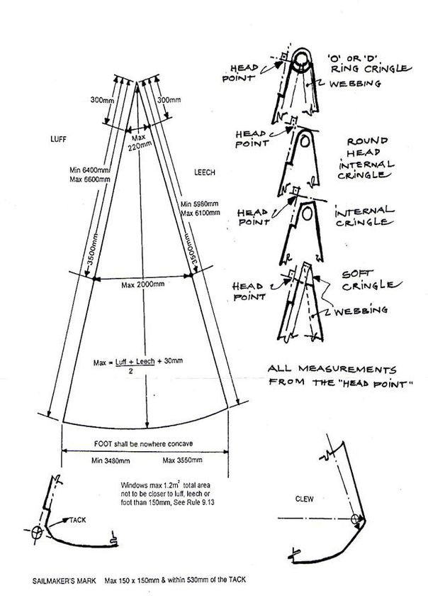
9.13 Windows made of non-woven material are permitted in each sail excluding spinnakers. The total area of the windows
in each sail shall not exceed 1.2 m2. No part of the window shall be closer to the luff, leech or foot than 150mm. The
width of the window seams shall not exceed 25mm. Non-woven material is not permitted in any reinforcement area.
9.14 The Class Insignia as shown below shall be positioned on the mainsail in accordance with RRS
Appendix G. For sails first certified prior to 1st May 2011 the insignia or just a letter D may be used.
(The Insignia is available in an electronic format from the IDA Secretary)
18You can also read