Mirage SST Installation and Setup Guide 020-102956-03 - Christie Digital
←
→
Page content transcription
If your browser does not render page correctly, please read the page content below

Installation and Setup Guide
                 020-102956-03

   Mirage SST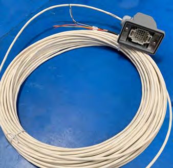
NOTICES
COPYRIGHT AND TRADEMARKS
Copyright © 2021 Christie Digital Systems USA Inc. All rights reserved.
All brand names and product names are trademarks, registered trademarks or trade names of their respective holders.
GENERAL
Every effort has been made to ensure accuracy, however in some cases changes in the products or availability could occur which may not be reflected in this
document. Christie reserves the right to make changes to specifications at any time without notice. Performance specifications are typical, but may vary
depending on conditions beyond Christie's control such as maintenance of the product in proper working conditions. Performance specifications are based on
information available at the time of printing. Christie makes no warranty of any kind with regard to this material, including, but not limited to, implied
warranties of fitness for a particular purpose. Christie will not be liable for errors contained herein or for incidental or consequential damages in connection
with the performance or use of this material. Manufacturing facilities in Canada and China are ISO 9001 certified.

Warranty
Products are warranted under Christie’s standard limited warranty, the details of which are available at https://www.christiedigital.com/help-center/
warranties/ or by contacting your Christie dealer or Christie.
PREVENTATIVE MAINTENANCE
Preventative maintenance is an important part of the continued and proper operation of your product. Failure to perform maintenance as required, and in
accordance with the maintenance schedule specified by Christie, will void the warranty.
REGULATORY
The product has been tested and found to comply with the limits for a Class A digital device, pursuant to Part 15 of the FCC Rules. These limits are designed
to provide reasonable protection against harmful interference when the product is operated in a commercial environment. The product generates, uses, and
can radiate radio frequency energy and, if not installed and used in accordance with the instruction manual, may cause harmful interference to radio
communications. Operation of the product in a residential area is likely to cause harmful interference in which case the user will be required to correct the
interference at the user’s own expense. Changes or modifications not expressly approved by the party responsible for compliance could void the user's
authority to operate the equipment
CAN ICES-3 (A) / NMB-3 (A)
이 기기는 업무용(A급)으로 전자파적합등록을 한 기기이오니 판매자 또는 사용자는 이점을 주의하시기 바라며, 가정 외의 지역에서 사용하는 것을 목적으로 합니다.
ENVIRONMENTAL
The product is designed and manufactured with high-quality materials and components that can be recycled and reused. This symbol            means that electrical
and electronic equipment, at their end-of-life, should be disposed of separately from regular waste. Please dispose of the product appropriately and according
to local regulations. In the European Union, there are separate collection systems for used electrical and electronic products. Please help us to conserve the
environment we live in!
Content
Introduction. . . . . . . . . . . . . . . . . . . . . . . . . . . . . . . . . . . . . . . . . . . . . . . . . . . . . . 6
    Important safeguards. . . . . . . . . . . . . . . . . . . . . . . . . . . . . . . . . . . . . . . . . . . . . . . . .6
         Safety and warning guidelines. . . . . . . . . . . . . . . . . . . . . . . . . . . . . . . . . . . . . . . . . 6
         Installation safety and warning guidelines. . . . . . . . . . . . . . . . . . . . . . . . . . . . . . . . . . 7
         AC power precautions. . . . . . . . . . . . . . . . . . . . . . . . . . . . . . . . . . . . . . . . . . . . . . .7
         Laser safety precautions. . . . . . . . . . . . . . . . . . . . . . . . . . . . . . . . . . . . . . . . . . . . . 8
         Light intensity hazard distance. . . . . . . . . . . . . . . . . . . . . . . . . . . . . . . . . . . . . . . . . 8
         Third-party products. . . . . . . . . . . . . . . . . . . . . . . . . . . . . . . . . . . . . . . . . . . . . . .13
    Product labels. . . . . . . . . . . . . . . . . . . . . . . . . . . . . . . . . . . . . . . . . . . . . . . . . . . . . 13
         General hazards. . . . . . . . . . . . . . . . . . . . . . . . . . . . . . . . . . . . . . . . . . . . . . . . . 13
         Mandatory action. . . . . . . . . . . . . . . . . . . . . . . . . . . . . . . . . . . . . . . . . . . . . . . . .14
         Electrical labels. . . . . . . . . . . . . . . . . . . . . . . . . . . . . . . . . . . . . . . . . . . . . . . . . . 14
         Laser labels. . . . . . . . . . . . . . . . . . . . . . . . . . . . . . . . . . . . . . . . . . . . . . . . . . . . 14
         Additional safety hazards. . . . . . . . . . . . . . . . . . . . . . . . . . . . . . . . . . . . . . . . . . . .15
    Product documentation. . . . . . . . . . . . . . . . . . . . . . . . . . . . . . . . . . . . . . . . . . . . . . . 15
         Related documentation. . . . . . . . . . . . . . . . . . . . . . . . . . . . . . . . . . . . . . . . . . . . . 16
    Technical support. . . . . . . . . . . . . . . . . . . . . . . . . . . . . . . . . . . . . . . . . . . . . . . . . . .16
    Projector overview. . . . . . . . . . . . . . . . . . . . . . . . . . . . . . . . . . . . . . . . . . . . . . . . . . 16
    Contact your dealer. . . . . . . . . . . . . . . . . . . . . . . . . . . . . . . . . . . . . . . . . . . . . . . . . 17
    Key features. . . . . . . . . . . . . . . . . . . . . . . . . . . . . . . . . . . . . . . . . . . . . . . . . . . . . .17
    How the projector works. . . . . . . . . . . . . . . . . . . . . . . . . . . . . . . . . . . . . . . . . . . . . . 17
    List of components. . . . . . . . . . . . . . . . . . . . . . . . . . . . . . . . . . . . . . . . . . . . . . . . . .18
    Chiller and laser illumination source components. . . . . . . . . . . . . . . . . . . . . . . . . . . . . . . 18

Installation and setup. . . . . . . . . . . . . . . . . . . . . . . . . . . . . . . . . . . . . . . . . . . . . . 19
    Site requirements. . . . . . . . . . . . . . . . . . . . . . . . . . . . . . . . . . . . . . . . . . . . . . . . . . 19
         Physical operating environment. . . . . . . . . . . . . . . . . . . . . . . . . . . . . . . . . . . . . . . . 19
         Power connection. . . . . . . . . . . . . . . . . . . . . . . . . . . . . . . . . . . . . . . . . . . . . . . . 19
    Projector components. . . . . . . . . . . . . . . . . . . . . . . . . . . . . . . . . . . . . . . . . . . . . . . . 20
    IR remote keypad. . . . . . . . . . . . . . . . . . . . . . . . . . . . . . . . . . . . . . . . . . . . . . . . . . 22
    Display panel components. . . . . . . . . . . . . . . . . . . . . . . . . . . . . . . . . . . . . . . . . . . . . 24
    Workflow: Installing and setting up the Mirage SST system. . . . . . . . . . . . . . . . . . . . . . . . 24
    Setting up the projector head. . . . . . . . . . . . . . . . . . . . . . . . . . . . . . . . . . . . . . . . . . . 26
         Leveling the projector. . . . . . . . . . . . . . . . . . . . . . . . . . . . . . . . . . . . . . . . . . . . . . 26

Mirage SST Installation and Setup Guide                                                                                       3
020-102956-03 Rev. 1 (03-2021)
Copyright © 2021 Christie Digital Systems USA, Inc. All rights reserved.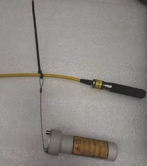
Content

         Installing the projector lens. . . . . . . . . . . . . . . . . . . . . . . . . . . . . . . . . . . . . . . . . . 27
         Connecting the projector head to AC power. . . . . . . . . . . . . . . . . . . . . . . . . . . . . . . . 28
    Setting up the laser illumination source. . . . . . . . . . . . . . . . . . . . . . . . . . . . . . . . . . . . . 28
         Installing the J33 terminal block on the laser illumination source. . . . . . . . . . . . . . . . . . . 29
         Protecting the fiber connector. . . . . . . . . . . . . . . . . . . . . . . . . . . . . . . . . . . . . . . . . 30
         Connecting the fiber optic cable to the projector through the curved strain relief. . . . . . . . . 33
         Connecting the fiber optic cable to the projector through the straight strain relief. . . . . . . . .35
         Connecting the Ethernet cable to the projector. . . . . . . . . . . . . . . . . . . . . . . . . . . . . . 38
    Setting up the chiller unit. . . . . . . . . . . . . . . . . . . . . . . . . . . . . . . . . . . . . . . . . . . . . 39
    Performing initial system start-up. . . . . . . . . . . . . . . . . . . . . . . . . . . . . . . . . . . . . . . . 40
         Turning on the system. . . . . . . . . . . . . . . . . . . . . . . . . . . . . . . . . . . . . . . . . . . . . 42
         Turning off the system. . . . . . . . . . . . . . . . . . . . . . . . . . . . . . . . . . . . . . . . . . . . . 44
         Projector LED status indicators. . . . . . . . . . . . . . . . . . . . . . . . . . . . . . . . . . . . . . . . 45
         Projector LED shutter indicators. . . . . . . . . . . . . . . . . . . . . . . . . . . . . . . . . . . . . . . 46
    Calibrating the lens motor. . . . . . . . . . . . . . . . . . . . . . . . . . . . . . . . . . . . . . . . . . . . . 46
         Removing the projection lens. . . . . . . . . . . . . . . . . . . . . . . . . . . . . . . . . . . . . . . . . 46
    Aligning the image. . . . . . . . . . . . . . . . . . . . . . . . . . . . . . . . . . . . . . . . . . . . . . . . . . 47
         Selecting a test pattern. . . . . . . . . . . . . . . . . . . . . . . . . . . . . . . . . . . . . . . . . . . . . 48
         Adjusting offset. . . . . . . . . . . . . . . . . . . . . . . . . . . . . . . . . . . . . . . . . . . . . . . . . .48
         Adjusting boresight. . . . . . . . . . . . . . . . . . . . . . . . . . . . . . . . . . . . . . . . . . . . . . . 48
         Adjusting the fold mirror. . . . . . . . . . . . . . . . . . . . . . . . . . . . . . . . . . . . . . . . . . . . 50
         Optimizing the integrator zoom and focus. . . . . . . . . . . . . . . . . . . . . . . . . . . . . . . . . 52
         Adjusting DMD convergence. . . . . . . . . . . . . . . . . . . . . . . . . . . . . . . . . . . . . . . . . . 54
         Aligning the image with lens zoom and focus. . . . . . . . . . . . . . . . . . . . . . . . . . . . . . . 55
         Running Auto Setup to optimize display settings. . . . . . . . . . . . . . . . . . . . . . . . . . . . . 55
    Configuring Mirage SST to work with Christie Link. . . . . . . . . . . . . . . . . . . . . . . . . . . . . . 56

Connecting devices and establishing communication. . . . . . . . . . . . . . . . . . . . . 57
    IMXB ports. . . . . . . . . . . . . . . . . . . . . . . . . . . . . . . . . . . . . . . . . . . . . . . . . . . . . . .57
    Connecting a video source using 3G input card. . . . . . . . . . . . . . . . . . . . . . . . . . . . . . . . 58
    Connecting a video source using DVI. . . . . . . . . . . . . . . . . . . . . . . . . . . . . . . . . . . . . . 58
    Connecting a video source using DisplayPort. . . . . . . . . . . . . . . . . . . . . . . . . . . . . . . . . .59
    Connecting a video source using HDMI. . . . . . . . . . . . . . . . . . . . . . . . . . . . . . . . . . . . . 59
    Connecting a video source using HBMIC. . . . . . . . . . . . . . . . . . . . . . . . . . . . . . . . . . . . 59
    Connecting a video source using TSIC. . . . . . . . . . . . . . . . . . . . . . . . . . . . . . . . . . . . . .59
    Selecting a video source. . . . . . . . . . . . . . . . . . . . . . . . . . . . . . . . . . . . . . . . . . . . . . 60
    Connecting to a computer or server. . . . . . . . . . . . . . . . . . . . . . . . . . . . . . . . . . . . . . . 60
    Configuring the RS232 port. . . . . . . . . . . . . . . . . . . . . . . . . . . . . . . . . . . . . . . . . . . . 61
    Setting up the Ethernet. . . . . . . . . . . . . . . . . . . . . . . . . . . . . . . . . . . . . . . . . . . . . . . 61

Mirage SST Installation and Setup Guide                                                                                     4
020-102956-03 Rev. 1 (03-2021)
Copyright © 2021 Christie Digital Systems USA, Inc. All rights reserved.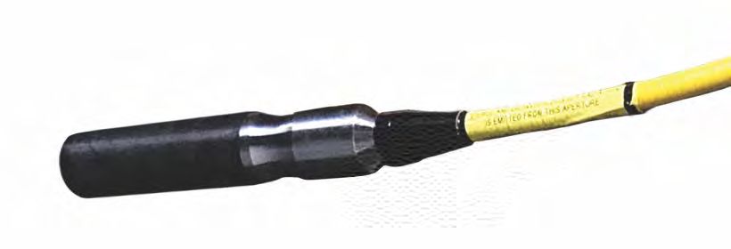
Content

3D setup. . . . . . . . . . . . . . . . . . . . . . . . . . . . . . . . . . . . . . . . . . . . . . . . . . . . . . . . 62
    3D requirements. . . . . . . . . . . . . . . . . . . . . . . . . . . . . . . . . . . . . . . . . . . . . . . . . . . 62
         Hardware requirements. . . . . . . . . . . . . . . . . . . . . . . . . . . . . . . . . . . . . . . . . . . . .62
         Software and content requirements. . . . . . . . . . . . . . . . . . . . . . . . . . . . . . . . . . . . . 62
    3D system timing. . . . . . . . . . . . . . . . . . . . . . . . . . . . . . . . . . . . . . . . . . . . . . . . . . 63
    3D input video configurations. . . . . . . . . . . . . . . . . . . . . . . . . . . . . . . . . . . . . . . . . . . 63
    Setting up a single projector to display 3D content. . . . . . . . . . . . . . . . . . . . . . . . . . . . . . 63
         Enabling 3D mode. . . . . . . . . . . . . . . . . . . . . . . . . . . . . . . . . . . . . . . . . . . . . . . . 63
         Confirming the emitter setup. . . . . . . . . . . . . . . . . . . . . . . . . . . . . . . . . . . . . . . . . 64
         Configuring the projector for the 3D source. . . . . . . . . . . . . . . . . . . . . . . . . . . . . . . . 64
    Connecting devices to the 3D sync ports. . . . . . . . . . . . . . . . . . . . . . . . . . . . . . . . . . . . 64

Regulatory. . . . . . . . . . . . . . . . . . . . . . . . . . . . . . . . . . . . . . . . . . . . . . . . . . . . . . 66
    Safety. . . . . . . . . . . . . . . . . . . . . . . . . . . . . . . . . . . . . . . . . . . . . . . . . . . . . . . . . 66
    Electro-magnetic compatibility. . . . . . . . . . . . . . . . . . . . . . . . . . . . . . . . . . . . . . . . . . 66
         Emissions. . . . . . . . . . . . . . . . . . . . . . . . . . . . . . . . . . . . . . . . . . . . . . . . . . . . . 66
         Immunity. . . . . . . . . . . . . . . . . . . . . . . . . . . . . . . . . . . . . . . . . . . . . . . . . . . . . 66
    Environmental. . . . . . . . . . . . . . . . . . . . . . . . . . . . . . . . . . . . . . . . . . . . . . . . . . . . 66

Signal connectivity specifications for . . . . . . . . . . . . . . . . . . . . . . . . . . . . . . . . . 68
    HBMIC video formats. . . . . . . . . . . . . . . . . . . . . . . . . . . . . . . . . . . . . . . . . . . . . . . . 68
    TSIC video formats. . . . . . . . . . . . . . . . . . . . . . . . . . . . . . . . . . . . . . . . . . . . . . . . . 70
    QDPIC video formats. . . . . . . . . . . . . . . . . . . . . . . . . . . . . . . . . . . . . . . . . . . . . . . . 70
    TDPIC video formats. . . . . . . . . . . . . . . . . . . . . . . . . . . . . . . . . . . . . . . . . . . . . . . . 71
    DDIC video formats. . . . . . . . . . . . . . . . . . . . . . . . . . . . . . . . . . . . . . . . . . . . . . . . . 71
    THIC video formats. . . . . . . . . . . . . . . . . . . . . . . . . . . . . . . . . . . . . . . . . . . . . . . . . 72
    3GIC video formats. . . . . . . . . . . . . . . . . . . . . . . . . . . . . . . . . . . . . . . . . . . . . . . . . 72
    Dual-input 3D and HFR 2D. . . . . . . . . . . . . . . . . . . . . . . . . . . . . . . . . . . . . . . . . . . . . 73

Mirage SST Installation and Setup Guide                                                                                     5
020-102956-03 Rev. 1 (03-2021)
Copyright © 2021 Christie Digital Systems USA, Inc. All rights reserved.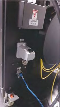
Introduction
This manual is intended for professionally trained operators of Christie high-brightness projection
systems.
              The illustrations in this document are for representation only and may not depict your projector model
              exactly.

Only Christie qualified technicians who are knowledgeable about the hazards associated with laser use,
high-voltage, and the high temperatures generated by the projector lasers are authorized to
assemble, install, and service the projector.
For complete Mirage SST product documentation and technical support, go to www.christiedigital.com.

Important safeguards
To prevent personal injury and to protect the device from damage, read and follow these safety
precautions. This projector is intended for use in a non-cinema environment.

Safety and warning guidelines
Read all safety and warning guidelines before installing or operating the projector.
This projector is intended for use in a fixed install environment (also known as a cinema environment).
This projector must be operated in an environment that meets the operating range specification. Use
only the attachments and/or accessories recommended by Christie. Use of others may result in the
risk of fire, shock, or personal injury.
              Warning! If not avoided, the following could result in death or serious injury.
                   •     This product must be operated in an environment that meets the operating range as specified in
                         this document.

                   •     Do not look directly into the lens when the light source is on. The extremely high brightness can
                         cause permanent eye damage.

                   •     ELECTRICAL and BURN HAZARD! Use caution when accessing internal components.

                   •     FIRE HAZARD! Keep hands, clothes, and all combustible material away from the concentrated
                         light beam of the projector.

                   •     Keep fingers and other body parts away from the moving parts in the product. Tie back long
                         hair, and remove jewelry and loose clothing before manually adjusting the product.

                   •     FIRE AND SHOCK HAZARD! Use only the attachments, accessories, tools, and replacement parts
                         specified by Christie.

                   •     Do not operate the product without a lens installed.

                   •     Always use a lens plug when installing or moving the product. This prevents contaminants from
                         entering the product.

                   •     FIRE AND SHOCK HAZARD! Use only the attachments, accessories, tools, and replacement parts
                         specified by Christie.

Mirage SST Installation and Setup Guide                                                                                  6
020-102956-03 Rev. 1 (03-2021)
Copyright © 2021 Christie Digital Systems USA, Inc. All rights reserved.
Introduction
Caution! If not avoided, the following could result in minor or moderate injury.
• TRIP OR FIRE HAZARD! Position all cables where they cannot contact hot surfaces, be pulled, be
tripped over, or damaged by persons walking on or objects rolling over the cables.
Installation safety and warning guidelines
Read all safety and warning guidelines before installing the projector.
Warning! If not avoided, the following could result in death or serious injury.
• Possible hazardous optical radiation emitted from this product. (Risk group 3)
• Christie products must be installed and serviced by Christie qualified technicians.
• Do not operate the product without all of its covers in place.
• A minimum of two people or appropriately rated lift equipment is required to safely lift, install,
or move the product.
• Always install safety straps when the frame and projector are installed overhead.
• Observe load ratings and applicable local safety codes.
• When installing the projector in portrait mode, the rigging device must have a sufficient load
rating, as identified in this manual.
• This product must be installed within a restricted access location not accessible by the general
public.
• Install the product so users and the audience cannot enter the restricted area at eye level.
• Only personnel who are trained on the precautions for the restricted access location can be
granted entry to the area.
• Only Christie qualified technicians are permitted to open product enclosures.
Caution! If not avoided, the following could result in minor or moderate injury.
• ELECTRICAL and BURN HAZARD! Use caution when accessing internal components.
• Only Christie qualified technicians are authorized to use the tools provided in the toolbox.
AC power precautions
Read all safety and warning guidelines before connecting to AC power.
Warning! If not avoided, the following could result in death or serious injury.
• SHOCK HAZARD! Only use the AC power cord provided with the product or recommended by
Christie.
• FIRE AND SHOCK HAZARD! Do not attempt operation unless the power cord, power socket, and
power plug meet the appropriate local rating standards.
• SHOCK HAZARD! Do not attempt operation if the AC supply is not within the specified voltage
and current, as specified on the license label.
• SHOCK HAZARD! The AC power cord must be inserted into an outlet with grounding.
• SHOCK HAZARD! A dedicated, protected ground or earth wire must be installed on the product
by Christie qualified technicians or electricians before it can be connected to power.
• SHOCK HAZARD! Disconnect the product from AC before installing, moving, servicing, cleaning,
removing components, or opening any enclosure.
• Install the product near an easily accessible AC receptacle.
Mirage SST Installation and Setup Guide 7
020-102956-03 Rev. 1 (03-2021)
Copyright © 2021 Christie Digital Systems USA, Inc. All rights reserved.Introduction
Caution! If not avoided, the following could result in minor or moderate injury.
• FIRE HAZARD! Do not use a power cord, harness, or cable that appears damaged.
• FIRE OR SHOCK HAZARD! Do not overload power outlets and extension cords.
• SHOCK HAZARD! Power supply uses double pole/neutral fusing. Disconnect all power sources
before opening the product.
Laser safety precautions
Read all safety and warning guidelines before operating the projector laser.
Warning! If not avoided, the following could result in death or serious injury.
• LASER RADIATION HAZARD! This projector has an external Class 4 laser module. Never attempt
to disassemble or modify the laser module.
• Possible hazardous optical radiation emitted from this product. (Risk group 3)
• Only Christie qualified technicians who are knowledgeable about the hazards associated with
laser use, high-voltage, and high temperatures generated by the product are authorized to
assemble, install, and service the Christie Laser Projection System.
• RADIATION HAZARD! Use of controls or adjustments, or performing procedures other than those
specified may result in hazardous radiation exposure.
• Do not look directly into the lens when the light source is on. The extremely high brightness can
cause permanent eye damage.
• Do not operate the product without all of its covers in place.
• LASER RADIATION! Do not short the contact rings.
• Always keep a protective cap on disconnected fiber optic cables.
Light intensity hazard distance
This projector has been classified as Risk Group 3 as per the IEC 62471-5:2015 standard due to
possible hazardous optical and thermal radiation being emitted.
Warning! If not avoided, the following could result in serious injury.
• PERMANENT/TEMPORARY BLINDNESS HAZARD! No direct exposure to the beam must be
permitted. Class 1 Laser Product - Risk Group 3 according to IEC 60825-1:2014 and IEC
62471-5:2015.
• PERMANENT/TEMPORARY BLINDNESS HAZARD! Operators must control access to the beam
within the hazard distance or install the product at the height that prevents exposure of
spectators' eyes within the hazard distance. The hazard zone must be no lower than 2.5 meters
(US installations) or 2.0 meters (global installations) above any surface upon which any persons
are permitted to stand and the horizontal clearance to the hazard zone must be a minimum 1.0
meters.
• EXTREME BRIGHTNESS! Do not place reflective objects in the product light path.
The following diagram and table show the zones for ocular and skin hazard distances:
Mirage SST Installation and Setup Guide 8
020-102956-03 Rev. 1 (03-2021)
Copyright © 2021 Christie Digital Systems USA, Inc. All rights reserved.Introduction
• A—Hazard zone. The region of space where the projection light from the laser-illuminated
projector is above emission limits for Risk Group 2. The light intensity may cause eye damage
after a momentary or brief exposure (before a person can avert his or her eyes away from the
light source). The light may cause skin burns to occur.
• B—Hazard distance. Operators must control access to the beam within the hazard distance or
install the product preventing potential exposure of the spectators' eyes from being in the
hazard distance.
• C—No access zone. Horizontal clearance of the no access zone must be a minimum of 1.0
meters.
• D—Vertical distance to hazard zone. The hazard zone must be no lower than 2.5 meters (US
installations) or 2.0 meters (global installations) above any surface upon which any persons
are permitted to stand.
• E—Represents the top view of the projector.
• F—Represents the side view of the projector.
The following table lists the hazard distance for the Christie projector lens with the zoom adjusted to
its most hazardous position.
For US and international hazard distances based upon IEC 62471-5:2015, Photobiological Safety of
Lamps and Lamp Systems – Part 5: Image Projectors.
Projection lens Part number Hazard distance (m)
Type A* Types B, C, D, E*
High brightness (HB) lenses
0.38:1 4K enhanced 144-136101-XX 1.0 1.0
0.72:1 HB fixed 144-110103-XX 1.0 1.0
0.9:1 fixed lens 144-111014-XX 1.2 1.0
1.13-1.31:1 HB zoom 144-103105-XX 1.6 1.4
1.13-1.66:1 HB zoom 144-129103-XX 2.1 1.8
Mirage SST Installation and Setup Guide 9
020-102956-03 Rev. 1 (03-2021)
Copyright © 2021 Christie Digital Systems USA, Inc. All rights reserved.Introduction
Projection lens Part number Hazard distance (m)
Type A* Types B, C, D, E*
1.31-1.63:1 HB zoom 144-104106-XX 2.1 1.8
1.45-2.17:1 HB zoom 144-130105-XX 2.8 2.5
1.63-2.17:1 HB zoom 144-105107-XX 2.7 2.4
1.95-3.26:1 HB zoom 144-131106-XX 4.1 3.6
1.99-2.71:1 HB zoom 144-106108-XX 3.4 3.0
2.71-3.89:1 HB zoom 144-107109-XX 4.8 4.3
3.89-5.43:1 HB zoom 144-108100-XX 7.0 6.0
4.98-7.69:1 HB zoom 144-109101-XX 9.9 8.6
Ultra high contrast (UHC) lenses
0.72:1 UHC fixed 163-116109-XX 1.0 1.0
0.9:1 UHC fixed 163-117100-XX 1.0 1.0
1.13-1.66 UHC zoom 163-118101-XX 1.7 1.6
1.45-2.17 UHC zoom 163-119102-XX 2.3 2.1
1.95-3.26 UHC zoom 163-120103-XX 3.4 3.1
2.71-3.89 UHC zoom 163-121105-XX 3.8 3.6
3.89-5.43 UHC zoom 163-122106-XX 5.4 5.1
* For specific Christie-supplied model names and part numbers, refer to the Mirage SST Projector
Head Specifications Guide (P/N: 020-102994-XX).
Type A 168-1011XX-XX
Type B 168-1061XX-XX
Type C 168-1071XX-XX
Type D 168-1081XX-XX
Type E 168-1091XX-XX
The below graphs are for reference only and the above hazard distance of the table must be followed.
Mirage SST Installation and Setup Guide 10
020-102956-03 Rev. 1 (03-2021)
Copyright © 2021 Christie Digital Systems USA, Inc. All rights reserved.Introduction Hazard distance graph for Type A high brightness and ultra high contrast lenses: Mirage SST Installation and Setup Guide 11 020-102956-03 Rev. 1 (03-2021) Copyright © 2021 Christie Digital Systems USA, Inc. All rights reserved.
Introduction

Hazard distance graph for Type B, C, D, E high brightness and ultra high contrast lenses:

For Installations in the United States
The following must be in place for laser-illuminated projector installations in the United States:
     •     Permanent show installations containing Risk Group 3 laser-illuminated projectors must meet
           the following conditions:
           •     Installed by Christie or by Christie-authorized and trained installers.
                 Refer to the Laser Illuminated Projector - Class 1 Risk Group 3 Installation training (Course
                 code: CF-LIPI-01) on the http://www.christieuniversity.com site.
           •     Performed according to instructions provided by Christie.
           •     Ensure the projection system is securely mounted or immobilized to prevent unintended
                 movement or misalignment of the projections.
     •     The projection room shall be clearly identified by the posting of laser warning and restricted
           access signs. The projection room sign must display the warning "Class 1 Risk Group 3 Laser
           Controlled Area No Direct Exposure to Beam Shall be Permitted".
     •     The Christie Laser Projection System Installation Checklist must be fully completed after the
           installation and sent to lasercompliance@christiedigital.com. A copy can remain on-site. This
           checklist can be found as a separate document in the accessory box with the manual.
     •     Certain US states have additional laser regulatory requirements. Contact
           lasercompliance@christiedigital.com for additional regulatory requirements.

Mirage SST Installation and Setup Guide                                                                     12
020-102956-03 Rev. 1 (03-2021)
Copyright © 2021 Christie Digital Systems USA, Inc. All rights reserved.
Introduction
Third-party products
This projector is certified to work only with certain specified third-party components. Use only Christie
approved third-party components with the projector. Using non-approved components with the
projector can lead to potential safety hazards and void the projector warranty.
For detailed safety information on third-party components, refer to the product documentation
provided by the manufacturer of the component.
Product labels
Learn about the labels that may be used on the product. Labels on your product may be yellow or
black and white.
General hazards
Hazard warnings also apply to accessories once they are installed in a Christie product that is
connected to power.
Fire and Shock Hazard
To prevent fire or shock hazards, do not expose this product to rain or moisture.
Do not alter the power plug, overload the power outlet, or use it with extension cords.
Do not remove the product enclosure.
Only Christie qualified technicians are authorized to service the product.
Electrical Hazard
Risk of electric shock.
Do not remove the product enclosure.
Only Christie qualified technicians are authorized to service the product.
Warning! If not avoided, the following could result in death or serious injury.
Electric shock hazard. To avoid personal injury, disconnect all power sources before
performing maintenance or service.
Electrocution hazard. To avoid personal injury, always disconnect all power sources
before performing maintenance or service procedures.
Optical radiation hazard. To avoid personal injury, never look directly at the light
source.
Laser hazard. To avoid personal injury, avoid eye or skin exposure to direct or
scattered radiations.
Mirage SST Installation and Setup Guide 13
020-102956-03 Rev. 1 (03-2021)
Copyright © 2021 Christie Digital Systems USA, Inc. All rights reserved.Introduction
Caution! If not avoided, the following could result in minor or moderate injury.
Hot surface hazard. To avoid personal injury, allow the product to cool for the
recommended cool down time before touching or handling for maintenance or
service.
Moving parts hazard. To avoid personal injury, keep hands clear and loose clothing
tied back.
Moving fan blade. To avoid personal injury, keep hands clear and loose clothing tied
back. Always disconnect all power sources before performing maintenance or service
procedures.
Notice. If not avoided, the following could result in property damage.
General hazard.
Not for household use.
Mandatory action
Disconnect all power sources before performing maintenance or service procedures.
Consult the service manual.
Electrical labels
Indicates the presence of a protective earth ground.
Laser labels
FDA laser variance (US projectors only)
This product conforms with performance standards for laser
products under 21 CFR Part 1040 except with respect to those
characteristics authorized by Variance Number 2019-V-0640
effective on March 8, 2019.
Mirage SST Installation and Setup Guide 14
020-102956-03 Rev. 1 (03-2021)
Copyright © 2021 Christie Digital Systems USA, Inc. All rights reserved.Introduction
Indicates a light hazard. Do not look directly into the lens. The
extreme high brightness can cause permanent eye damage. Class 1
Laser Product - Risk Group 3 according to IEC 60825-1: 2014 and
IEC 62471-5:2015
Indicates the product is certified for use with the listed Christie-
supplied light illumination sources.
Indicates a danger Class 4 laser radiation when open and interlocks
are defeated. Avoid eye or skin exposure to direct or scattered
radiation. Turn off power before removing the bracket.
Additional safety hazards
Do not look directly into the lens. The extremely high brightness
can cause permanent eye damage.
Indicates high leakage current. Earth connection essential before
connecting the power supply.
Product documentation
For installation, setup, and user information, see the product documentation available on the Christie
website. Read all instructions before using or servicing this product.
1. Access the documentation from the Christie website:
• Go to this URL: http://bit.ly/2TI2aEW or
https://www.christiedigital.com/en-us/3d/products-and-solutions/projectors/mirage-sst.
• Scan the QR code using a QR code reader app on a smartphone or tablet.
Mirage SST Installation and Setup Guide 15
020-102956-03 Rev. 1 (03-2021)
Copyright © 2021 Christie Digital Systems USA, Inc. All rights reserved.Introduction
2. On the product page, switch to the Downloads tab.
Related documentation
Additional information on this product is available in the following documents.
• Mirage SST Product Safety Guide (P/N: 020-102992-XX)
• Mirage SST User Guide (P/N: 020-102993-XX)
• Mirage SST Projector Head Specifications Guide (P/N: 020-102994-XX)
• Mirage SST Status System Guide (P/N: 020-103007-XX)
• Mirage SST Serial Commands Guide (P/N: 020-103005-XX)
• Mirage SST Projector Head Service Guide (P/N: 020-103039-XX)
Technical support
Technical support for Christie Enterprise products is available at:
• North and South America: +1-800-221-8025 or Support.Americas@christiedigital.com
• Europe, Middle East, and Africa: +44 (0) 1189 778111 or Support.EMEA@christiedigital.com
• Asia Pacific (support.apac@christiedigital.com)
• Australia: +61 (0)7 3624 4888 or tech-Australia@christiedigital.com
• China: +86 10 6561 0240 or tech-supportChina@christiedigital.com
• India: +91 (80) 6708 9999 or tech-India@christiedigital.com
• Japan: 81-3-3599-7481
• Singapore: +65 6877-8737 or tech-Singapore@christiedigital.com
• South Korea: +82 2 702 1601 or tech-Korea@christiedigital.com
• Christie Professional Services: +1-800-550-3061 or NOC@christiedigital.com
Projector overview
Learn about the Mirage SST projectors.
Mirage SST are professional quality projectors using Digital Light Processing (DLPTM) technology from
Texas Instruments. Mirage SST are engineered specifically for complex, high-end applications like
planetariums, dome theaters, and theme park attractions to offer stunning wide screen, high
resolution 4K images up to 120 frames (for Mirage SST) per second.
The systems can be 3P (single) or 6P (dual).
Mirage SST provide several design and installation advantages. Their small form factor allows them to
be installed independently, or as part of a multi-projector array, into tight, challenging environments.
Mirage SST Installation and Setup Guide 16
020-102956-03 Rev. 1 (03-2021)
Copyright © 2021 Christie Digital Systems USA, Inc. All rights reserved.Introduction
Both single (3P) and dual (6P) systems are available. The remote light source also allows the chilling
equipment to be located away from the projector head where its noise will not impact the audience’s
enjoyment of the show.
Contact your dealer
Record the information about your projector and keep this information with your records to assist with
the servicing of your projector. If you encounter a problem with your Christie projector, contact your
dealer.
Purchase record
Dealer:
Dealer or Christie Sales/Service contact phone number:
Projector serial number:
The serial number can be found on the license label located on the display panel
Purchase date:
Installation date:
Ethernet settings
Default gateway
Projector IP address
Subnet mask
Key features
Understand the important features of the projector.
• Built in warp and blend of projected images
• Improved lens mount with bayonet style insertion
• Single phase 100-240 V
• Side access to optical adjustments
• 4K resolution for flexibility and future proofing
• Omnidirectional operation
• TruLife electronics
• LCD display to provide information at-a-glance
How the projector works
The Mirage SST accepts a variety of input signals for projection on front or rear projection screens,
typical in commercial or other large screen applications.
High-brightness light is generated by a laser illumination source, then fed to the projector through a
fiber optic cable, where it is modulated by three Digital Micromirror Device (DMD) panels responding
Mirage SST Installation and Setup Guide 17
020-102956-03 Rev. 1 (03-2021)
Copyright © 2021 Christie Digital Systems USA, Inc. All rights reserved.Introduction
to incoming data streams of digitized red, green and blue color information. Based on digital signals
from the source, light from the responding on pixels of each panel is reflected, converged and then
projected to the screen through a projection lens, where all pixel reflections are superimposed into a
sharp full-color image.
The Mirage SST projector head provides all configuration and control for the laser illumination source.
Never connect a laptop to the laser illumination source unless directed by Technical Support.
List of components
Verify all components were received with the projector.
• Power cord
• IR remote keypad
• Network cable
• Tools
• Fiber optic support
• Laser illumination source J33 terminal block 1 (P/N: 001-114198-XX)
• Fiber connector safety cover
Chiller and laser illumination source
components
For information on the approved chiller and laser illumination source products, see the Mirage SST
Projector Head Specifications Guide (P/N: 020-102994-XX).
• Laser unit, including attached fiber optic cable
• Third-party chiller unit
Mirage SST Installation and Setup Guide 18
020-102956-03 Rev. 1 (03-2021)
Copyright © 2021 Christie Digital Systems USA, Inc. All rights reserved.Installation and setup
Learn how to install, connect, and optimize the projector display.
Site requirements
To safely install and operate the projector, the installation location must have restricted access for
authorized personnel only and meet these minimum requirements.
Physical operating environment
Provides specifications for the operating environment.
• Ambient temperature (operating) up to 500 m (1640.42 ft):
• Type A: 10 to 24°C (50 to 75°F) at full power and at reduced power above 24°C (75°F)
• Type B: 10 to 30°C (50 to 86°F) at full power and at reduced power above 30°C (86°F)
• Type C, D, E : 10 to 35°C (50 to 95°F) at full power
• Humidity (non-condensing) 20 to 80%
• Operating altitude: 3,000 m (10,000 ft) maximum at 10 to 25°C (50 to 77°F) ambient
Power connection
A 15A rated wall breaker is required at the installation of the projector.
Ensure a qualified electrician connects the AC power to the laser illumination source and chiller as per
electrical codes.
Mirage SST Installation and Setup Guide 19
020-102956-03 Rev. 1 (03-2021)
Copyright © 2021 Christie Digital Systems USA, Inc. All rights reserved.Installation and setup
Projector components
Identify the main components of the projector.
ID Component Description
A Projection lens A variety of lenses can be used with the projector. Available lenses are
listed in accessories.
B Front filter door Provides access to the front air filter.
C Front IR Receives transmissions from the IR remote.
D Mounting and rigging holes M12 x 1.75 holes for projector feet installation and offer mounting and
rigging points.
E Service compartment Access to fold mirror, optical zoom/focus, and DMD convergence
adjustments.
F Display panel Displays the projector menu and status.
Mirage SST Installation and Setup Guide 20
020-102956-03 Rev. 1 (03-2021)
Copyright © 2021 Christie Digital Systems USA, Inc. All rights reserved.Installation and setup
ID Component Description
G Keypad interface Controls the projector.
H Adjustable feet Raise or lower these feet when positioning the projector to make sure it
is level on all sides so the displayed image appears rectangular without
any keystone.
I Power switch Shuts off AC power.
J AC input and lock Use this IEC 320-C14 inlet to connect to an appropriately rated power
cord provided for your region and lock it in place.
K Light source input Receives the input for the light source. Remove the security bracket
before plugging in the light source.
L Communication and input Access to fold mirror, optical zoom/focus, and DMD convergence
panel adjustments.
M Rear IR Receives transmissions from the IR remote.
N LED status indicator Indicates lamp and power status.
O Shutter LED status indicator Indicates shutter status.
P Air filter side Provides access to the side air filter.
Mirage SST Installation and Setup Guide 21
020-102956-03 Rev. 1 (03-2021)
Copyright © 2021 Christie Digital Systems USA, Inc. All rights reserved.Installation and setup IR remote keypad The IR remote keypad controls the projector by way of wireless communications from a battery- powered infrared (IR) transmitter. Button Description A Powers on the projector light source. B Opens the aspect ratio dialog. Mirage SST Installation and Setup Guide 22 020-102956-03 Rev. 1 (03-2021) Copyright © 2021 Christie Digital Systems USA, Inc. All rights reserved.
Installation and setup

 Button           Description
 C                Turns off the light source and puts the projector in standby.

 D                Selects an active or inactive input on any slot.

 E                Not supported.

 F                Enter a number, such as menu, item index or value.

 G                Use the arrows to navigate within a menu or to adjust settings.

 H                Selects a highlighted menu item and changes or accepts a value.

 I                Toggles the menus on/off.

 J                Not supported.

 K                Opens the keystone dialog.

 L                Adjusts the lens focus.

 M                Not supported.

 N                Displays a test pattern.

 O                Not supported.

 P                Optimizes the image automatically.

 Q                Opens or closes the shutter.

 R                Not supported.

 S                Initiates a custom action when a number is selected.

 T                Selects a projector in multi-projector installations.

 U                Returns to the previous menu level or exits menus if at the top level.

 V                Displays context-sensitive help.

 W                Arrows adjust the lens offset.

 X                Adjust the lens zoom.

 Y                Opens the on-screen display position menu.

 Z                Shows or hides the on-screen display menus.

 AA               Turns the remote backlight on.

 AB               Male 3-pin XLR connector for wired option.

 AC               Lock/unlock the keypad.

 AD               Battery door.

Mirage SST Installation and Setup Guide                                                                        23
020-102956-03 Rev. 1 (03-2021)
Copyright © 2021 Christie Digital Systems USA, Inc. All rights reserved.
Installation and setup

Display panel components
Identify the main components of the display panel (also known as the home page).

 ID              Component                                      Description
 A               Projector information                          Provides information about the projector such as the projector
                                                                name, serial number, software version, and projector ID.

 B               Projector and Component                        Indicates the states of the projector and its components.
                 Controls

 C               Power and Temperature                          Indicates the light source mode, power mode, and intake
                                                                temperature.

 D               Status                                         Contains information about the health of the projector including
                                                                the number of warnings and errors.
                                                                Provides access to the status system.

 E               IP Settings                                    Indicates the incoming voltage, measured in Volts, and intake
                                                                temperature, measured in Celsius.

 F               Test Pattern                                   Displays the currently selected test pattern. If no test pattern is
                                                                selected, Off is displayed.
                                                                Provides access to the list of test patterns.

 G               Input                                          Displays the signal for the currently selected input.
                                                                Provides access to the list of input signals.

Workflow: Installing and setting up the Mirage
SST system
Identify the recommended order for installing and setting up the components of the Mirage SST
system.
These tasks detail the steps for installing both single (3P) and dual (6P) systems. For the dual system,
repeat the tasks for both the left-eye and right-eye systems, making sure you connect the correct
light source to the correct projector head.

Mirage SST Installation and Setup Guide                                                                                               24
020-102956-03 Rev. 1 (03-2021)
Copyright © 2021 Christie Digital Systems USA, Inc. All rights reserved.
Installation and setup
Legend
Chiller unit
Laser illumination
source
Projector
Chiller hoses
Fiber optic cables
AC input cables
Laser Ethernet cable
The Mirage SST projector head provides all configuration and control for the laser illumination source.
Never connect a laptop to the laser illumination source unless directed by Technical Support.
1. Set up the projector head (on page 26).
a) Position the projector as perpendicular to the screen as possible, even if significantly
above the screen center.
b) Install the projection lens (on page 27).
c) If required, connect the Ethernet cable (on page 60) from the Ethernet port on the
projector head to the input source.
d) Connect the projector head to AC power (on page 28).
2. Set up the laser illumination source (on page 28).
a) Position the laser illumination source on level ground and ensure the fiber optic cable is
routed in a way to avoid any damage.
b) Install the J33 terminal block (on page 29) on the laser illumination source.
c) To protect the fiber optic cable, install the fiber connector safety cover (on page 30) on
the fiber connector.
d) Connect the fiber optic cable from the laser illumination source to the projector head.
• Connect using the curved strain relief (on page 33).
• Connect using the straight strain relief (on page 35).
e) Ensure a qualified electrician connects the AC power to the laser illumination source.
3. Set up the chiller unit (on page 28).
4. Perform initial system start-up (on page 40) or turn on the system (on page 42).
5. Calibrate the lens motor (on page 46).
6. Align the image (on page 47).
a) Adjust the offset (on page 48).
Mirage SST Installation and Setup Guide 25
020-102956-03 Rev. 1 (03-2021)
Copyright © 2021 Christie Digital Systems USA, Inc. All rights reserved.Installation and setup
b) Adjust the boresight (on page 48).
c) Adjust the fold mirror (on page 50).
d) Optimize the integrator zoom and focus (on page 52).
e) Adjust the DMD convergence (on page 54).
f) Align the image with lens zoom and focus (on page 55).
g) Run Auto Setup to optimize display settings (on page 55).
7. Configure Mirage SST to work with Christie Link (on page 56).
Setting up the projector head
1. Position the projector as perpendicular to the screen as possible, even if significantly above the
screen center.
When a particularly short throw distance combines with a wide screen, you may have to forfeit
some aim and stay more perpendicular to the screen. In such cases, some lens offset can
reduce the keystone distortion.
For information on positioning the projector in a rigging frame, refer to the Assembling the
Precision 1 Rigging Frame (P/N: 020-102719-XX) or Upgrading the Boxer Rigging Frame (P/N:
020-102746-XX) instruction sheet.
2. Level the projector (on page 26) as required.
3. Install the projection lens (on page 27).
4. If required, connect the Ethernet cable (on page 60) from the Ethernet port on the projector
head to the input source.
5. Connect the projector head to AC power (on page 28).
Leveling the projector
Use the projector feet to level the projector.
1. To adjust the vertical position of the projector, extend or retract the adjustable feet on the
bottom of the projector using the adjustable knobs on the feet.
Mirage SST Installation and Setup Guide 26
020-102956-03 Rev. 1 (03-2021)
Copyright © 2021 Christie Digital Systems USA, Inc. All rights reserved.Installation and setup
2. Once the required adjustment is made, using a wrench, tighten the lock nut against the
bottom of the projector.
Installing the projector lens
Only use lenses designed for Mirage SST projectors. Installing a lens not designed for Mirage SST,
results in a warning that the lens is not present.
1. Remove the lens caps from the lens.
The packaging tape is required to ensure safe shipment of the projection lens to restrain the
zoom ring from rotating during shipping.
2. Align the guides on the front cover and the lens marked by a red line.
3. Insert the lens into the projector and turn it clockwise until you hear two clicks.
The first click indicates the safety lock mechanism has been engaged.
4. Continue to turn the lens clockwise until you hear a second click.
The second click indicates the lens is fully locked in position. The top center label should face
up and be aligned to the lens guide on the front cover.
Mirage SST Installation and Setup Guide 27
020-102956-03 Rev. 1 (03-2021)
Copyright © 2021 Christie Digital Systems USA, Inc. All rights reserved.Installation and setup
Connecting the projector head to AC power
Connect the projector head to the AC power.
1. On the projector head, ensure the AC breaker/switch is in the off position.
2. Connect AC power to the AC inlet on the projector.
For electrical rating information, refer to the license label on the projector.
3. To ensure the AC power cord does not fall out, pull out the safety retainer clip from the holder
and clip over the power cord connector.
To unplug, raise up the retainer clip and pull out the cord.
Setting up the laser illumination source
1. Position the laser illumination source on level ground and ensure the fiber optic cable is routed
in a way to avoid any damage.
Mirage SST Installation and Setup Guide 28
020-102956-03 Rev. 1 (03-2021)
Copyright © 2021 Christie Digital Systems USA, Inc. All rights reserved.Installation and setup
2. Install the J33 terminal block (on page 29) on the laser illumination source.
3. To protect the fiber optic cable, install the fiber connector safety cover (on page 30) on the
fiber connector.
4. Connect the fiber optic cable from the laser illumination source to the projector head.
• Connect using the curved strain relief (on page 33).
• Connect using the straight strain relief (on page 35).
5. Connect the laser Ethernet cable (on page 38) from the laser illumination source to the
projector head.
6. Ensure a qualified electrician connects the AC power to the laser illumination source.
For electrical rating information, refer to the license label on the laser illumination source.
Additional information is available in the laser illumination source's product documentation.
Installing the J33 terminal block on the laser illumination
source
The J33 terminal block on the light illumination source is used for an external interlock E-stop and fire
alarm E-stop triggers. The J33 terminal block closes off the connector to the interlock allowing Mirage
SST to turn on.
As of October 2020, a J33 terminal block and a 30.4 m (100 foot) cable are optionally available with
the laser rack to enable the Power key in the remote position. For racks purchased before this date,
contact Christie Technical Support for information on upgrading the laser rack to use this feature.
Determine which terminal block and features you require:
• J33 terminal block 1—Self-contained with no external wires and shipped with the projector
head packaging. Use this terminal block when manual control and no external E-stop are
required. If using the J33 terminal block 1, remote operation or remote E-stop is not available.
• J33 terminal block 2—Includes a 30.4 m (100 foot) cable. Use this terminal block when
external control and/or an external E-stop are required.
1. On the laser rack, install either the J33 connector with cable provided with the laser rack or the
J33 connector provided with the projector.
• J33 terminal block 1—Install the J33 terminal block by tightening the two screws.
J33 terminal block 1
shown here with the
location of the
mounting screws
indicated with the red
arrows
• J33 terminal block 2—Install the J33 terminal block with the integrated cable (in the same
location as shown above for the J33 terminal block 1) by tightening the two screws and
proceed to step 2.
Mirage SST Installation and Setup Guide 29
020-102956-03 Rev. 1 (03-2021)
Copyright © 2021 Christie Digital Systems USA, Inc. All rights reserved.Installation and setup
Terminal block 2 shown below with cable:
Terminal block 2 shown
here with cable
Terminate all wires or the projector may not operate.
2. To make use of the remote operation feature (J33 terminal block option 2), terminate the wires
for correct operation.
Each wire has a label indicating what pin it is connected to.
a) Ensure pins/wires 17 to 20 and 18 to 19 are closed or the projector will not operate in the
local or remote position.
These pins can be connected to a remote E-stop button and/or the remote fire disconnect
and/or each circuit closed if the remote E-stop is not required. Keep each circuit isolated
from other circuits.
b) Wire the automation device to provide the ability to maintain a closed circuit between the
J33 pins 8 and 9 when the equipment is operating.
This circuit is used to turn the laser illumination source on and off. When the circuit is open
and the key is in the REM position, functionally this is the same as if the key was turned to
off.
c) Wire the automation device to provide the ability to momentarily close the circuit between
the J33 pins 21 and 22.
This circuit is used to turn on the lasers when the key is in the REM position. Functionally
it is the same as pressing the green button when the key is in the ON position.
The green button/light illuminates when this contact is closed (if the system is ready);
however, the button does not operate as a button. It is only a light when the key is in the
REM position.
A momentary 500ms contact closure is required to turn on the lasers with pins 21 and 22.
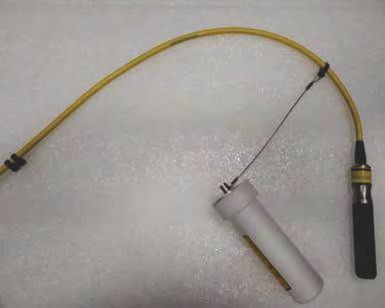
Protecting the fiber connector
Before placing or setting up any system components, you must install the supplied fiber connector
safety cover on the fiber connector to protect the fiber optic cable.
The fiber connector safety cover, wire lanyard, and cable ties, are supplied in the projector package.
The fiber connector safety cover provides additional physical protection for the fiber connector to
reduce the risk of damage during installation work.
Mirage SST Installation and Setup Guide 30
020-102956-03 Rev. 1 (03-2021)
Copyright © 2021 Christie Digital Systems USA, Inc. All rights reserved.Installation and setup
The fiber connector safety cover (safety cover) must be tethered to the fiber optic cable and then
placed over the fiber connector and its dust cap. The safety cover and dust cap should be removed
only when you are ready to connect the fiber optic cable to the projector.
When handling the fiber optic cable, the minimum bend radius allowed is 150 mm.
Legend
A Fiber connector safety cover
B Captive screw
C Cover lid
D Wire lanyard
E Eye of wire lanyard
1. Slide a cable tie through the eye of the wire lanyard and loop the cable tie loosely around the
fiber optic cable.
Mirage SST Installation and Setup Guide 31
020-102956-03 Rev. 1 (03-2021)
Copyright © 2021 Christie Digital Systems USA, Inc. All rights reserved.Installation and setup
When attached to the fiber optic cable, make sure the tethered safety cover can be placed over
the fiber connector and the cable tie is sufficiently loose to slide the tether up and down the
fiber cable.
2. Measure a distance approximately 650 mm (25.6 inches) from the end of the fiber connector
down the fiber cable.
3. At this location, create a stop point by placing one cable tie and tightening it.
4. At this same location, place a second cable tie directly beside the first one and tighten it.
To form the stop point, both cable ties should be tightened sufficiently so they cannot slide
down the fiber optic cable.
5. Make sure the tethered safety cover cannot slide past the stop point.
6. Trim all the cable ties.
7. Slide the tethered safety cover back to the connector end and place the cover over the fiber
connector and its dust cap.
Mirage SST Installation and Setup Guide 32
020-102956-03 Rev. 1 (03-2021)
Copyright © 2021 Christie Digital Systems USA, Inc. All rights reserved.Installation and setup
A Fiber connector
B Dust cap
8. Close the safety cover lid using a #2 Phillips screwdriver to tighten the captive screw.
The tethered safety cover must remain installed on the fiber connector whenever the fiber
optic cable is not connected to the projector.
When the fiber optic cable is connected to the projector, store the fiber connector dust cap
inside the tethered safety cover.
Connecting the fiber optic cable to the projector through the
curved strain relief
Attach the fiber optic cables from the laser illumination source to the projector using a curved strain
relief.
For additional information on the laser illumination source and the fiber optic cable, refer to the laser
illumination source's product documentation.
1. On the rear of the projector, loosen the captive screw securing the laser safety bracket.
2. Remove the fiber connector safety cover.
3. Remove the dust cover from the fiber input location.
4. To remove the top clamp from the bottom of the strain relief, remove the four screws.
Mirage SST Installation and Setup Guide 33
020-102956-03 Rev. 1 (03-2021)
Copyright © 2021 Christie Digital Systems USA, Inc. All rights reserved.Installation and setup
5. Discard the dummy rod located inside the protective pad.
6. Feed the fiber optic cable with the fiber connector dust cap attached on the tip through the
strain relief.
7. Remove the dust cap from the end of the fiber optic cable and store it in the safety cover.
8. To secure the fiber connector dust cap inside the safety cover, tighten the captive screw.
9. Insert the fiber optic cable into the fiber input ensuring the red dots line up.
10. To lock in place, turn the locking collar clockwise until you see the locking pin start to turn and
no longer moves forward.
11. Attach the strain relief to the projector and tighten the two captive screws to secure it.
12. Wrap the fiber optic cable inside the protective pad and position in the groove.
Mirage SST Installation and Setup Guide 34
020-102956-03 Rev. 1 (03-2021)
Copyright © 2021 Christie Digital Systems USA, Inc. All rights reserved.Installation and setup
13. To install the back portion of the clamp over the fiber optic cable and tighten the four screws
removed in step 4.
Connecting the fiber optic cable to the projector through the
straight strain relief
Attach the fiber optic cables from the laser illumination source to the projector using a straight strain
relief.
For additional information on the laser illumination source and the fiber optic cable, refer to the laser
illumination source's product documentation.
1. Remove the curved portion of the strain relief.
a) Remove the three screws securing the top of the curved portion of the strain relief to the
straight portion.
b) Remove the two screws securing the clamps from the curved portion of the strain relief.
Mirage SST Installation and Setup Guide 35
020-102956-03 Rev. 1 (03-2021)
Copyright © 2021 Christie Digital Systems USA, Inc. All rights reserved.Installation and setup
c) Re-install the clamp to the pieces to the straight portion of the strain relief using the two
screws removed in step b.
2. On the rear of the projector, loosen the captive screw securing the laser safety bracket.
3. Remove the fiber connector safety cover.
4. Remove the dust cover from the fiber input location.
5. To remove the top clamp from the bottom of the strain relief, remove the four screws.
Mirage SST Installation and Setup Guide 36
020-102956-03 Rev. 1 (03-2021)
Copyright © 2021 Christie Digital Systems USA, Inc. All rights reserved.Installation and setup
6. Discard the dummy rod located inside the protective pad.
7. Feed the fiber optic cable with the fiber connector dust cap attached on the tip through the
strain relief.
8. Remove the dust cap from the end of the fiber optic cable and store it in the safety cover.
9. To secure the fiber connector dust cap inside the safety cover, tighten the captive screw.
10. Insert the fiber optic cable into the fiber input ensuring the red dots line up.
11. To lock in place, turn the locking collar clockwise until you see the locking pin start to turn and
no longer moves forward.
12. Attach the strain relief to the projector and tighten the two captive screws to secure it.
13. Wrap the fiber optic cable inside the protective pad and position in the groove.
Mirage SST Installation and Setup Guide 37
020-102956-03 Rev. 1 (03-2021)
Copyright © 2021 Christie Digital Systems USA, Inc. All rights reserved.You can also read