R&SZNA VECTOR NETWORK ANALYZER - Masters the most challenging measurement tasks
←
→
Page content transcription
If your browser does not render page correctly, please read the page content below
R&S®ZNA
VECTOR NETWORK ANALYZER
                               year

Masters the most challenging
measurement tasks

Product Brochure
Version 02.00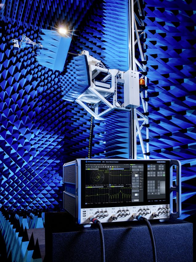
2
CONTENTS
Overview Applications
At a glance Compression point m
easurements
► page 4 ► page 25
State-of-the-art user interface Intermodulation measurements on amplifiers and mixers
► page 6 ► page 26
Rear panel connections Pulsed measurements – fast and simple
► page 8 ► page 28
Mixer measurements easier than ever
► page 30
Highlights Spectrum analysis with multichannel view
► page 32
Unique operating concept with two touchscreens
► page 10 Time domain analysis and signal integrity measurements
► page 33
Top-class hardware c omponents
► page 12 Antenna measurements – the perfect fit
► page 34
Unprecedented RF quality
► page 14 mmWave measurements
► page 36
Hardware options
► page 15
The right calibration for every test scenario
► page 20 Additional information
Ordering information
► page 40
From pre-sale to s ervice. At your doorstep.
► page 43
The terms HDMI and HDMI High-Definition Multimedia Interface, and the HDMI Logo are trademarks or registered trademarks of HDMI Licensing LLC
in the United States and other countries.
Rohde & Schwarz R&S®ZNA Vector Network Analyzer 3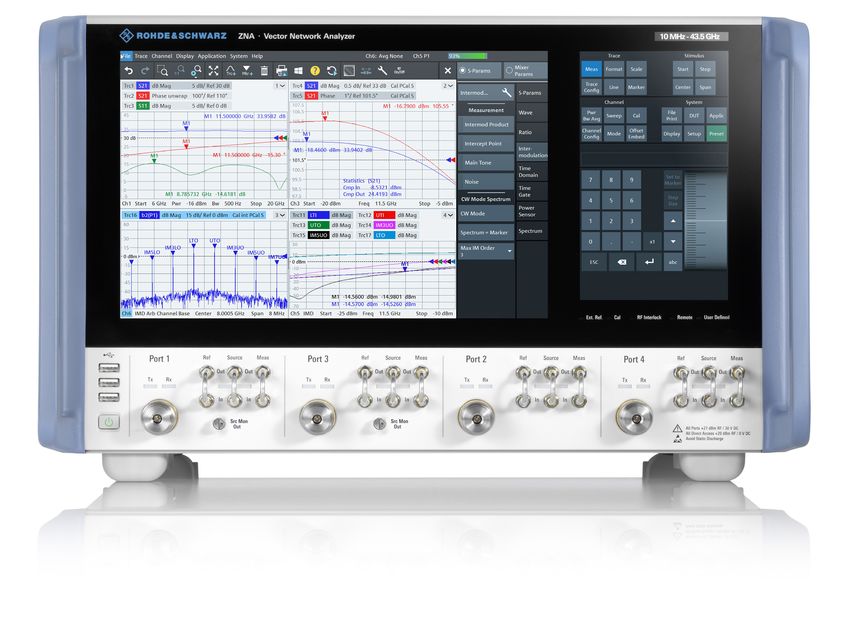
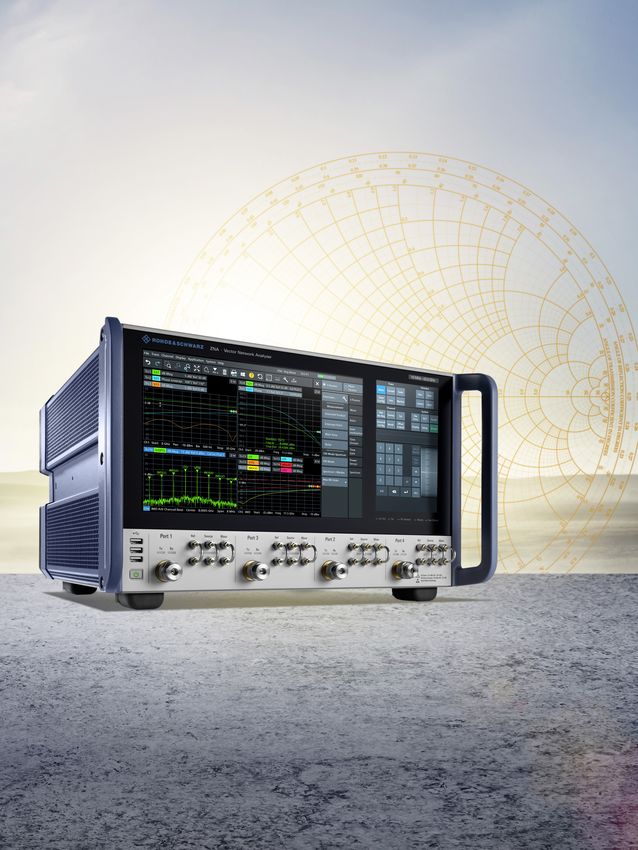
AT A GLANCE
Offering outstanding RF characteristics and a unique hardware architecture, the R&S®ZNA high-end
vector network analyzer makes demanding measurements easier than ever. Another exceptional feature
is the analyzer's DUT-centric operating concept, which guides users quickly and conveniently to the
desired measurement setup. Two independent touchscreens provide utmost flexibility for smooth, efficient
operation.
The R&S®ZNA features exceptional stability, low trace Thanks to the phase-coherent digital sources and
noise and excellent raw data, making it a perfect choice receivers, no reference mixers are needed for mixer
for development and production applications that require phase measurements, and test setups are configured just
high accuracy, e.g. for developing and producing compo- as easily as for non-frequency-converting S-parameter
nents and modules for A&D and satellite applications. measurements.
The R&S®ZNA offers four internal, phase-coherent sources, The analyzer's DUT-centric operating concept makes
allowing independent control of the signal's frequency it possible to achieve the desired setup at an unrivaled
at each port as well as phase measurements on mixers. speed. Users no longer need to work through a jungle
It provides two internal LO sources, a true multichannel of menus. Instead, a wizard guides them step by step
receiver architecture, pulse generators and modulators, through configuration and calibration. All relevant
an internal combiner and comprehensive trigger and syn- parameters are covered, and measurement traces are
chronization capabilities. These hardware features make created in just a few steps.
the R&S®ZNA a universal, compact test system for active
and passive device characterization. Even intermodulation The R&S®ZNA characterizes low-noise amplifiers (LNA),
measurements on mixers and receivers can be performed receivers, frequency-converting DUTs and T/R modules
without external signal generators, minimizing test time precisely and efficiently; the DUT needs to be connected
and simplifying test configuration. only once.
Users can operate the R&S®ZNA via two
independent touchscreens.
4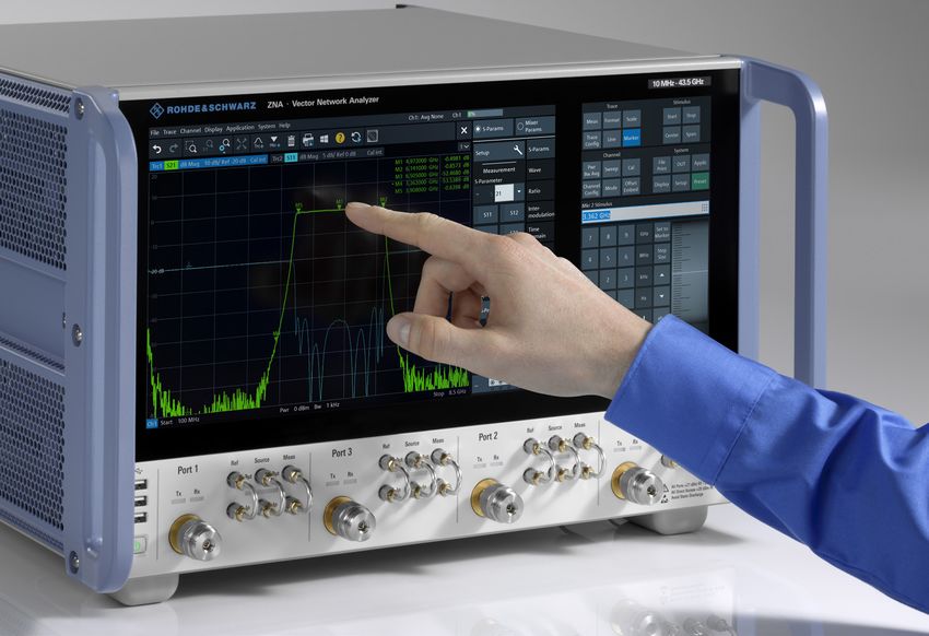
The instrument provides numerous software applica- R&S®ZNA models
tions, e.g. for intuitive configuration of group delay and
spectrum measurements.
6
Hz -B1
0 k xx
10 NA
z
z
GH
GH
Hz
Z
Various menu-based calibration procedures are available
S®
M
.5
.5
R&
10
26
43
to help users calibrate even complicated setups efficiently
and reliably. All the calibration methods supported by the
R&S®ZNA can be expanded using a special calibration R&S®ZNA26
technique referred to as R&S®SMARTerCal. This technique 2-port and 4-port, 2 and 4 sources
combines system error correction with absolute power
level correction, minimizing the number of calibration
steps even with active DUTs, which involve considerable R&S®ZNA43
2-port and 4-port, 2 and 4 sources
measurement effort.
KEY FACTS AND BENEFITS
Four internal phase-coherent sources Phase measurements on mixers without reference mixers
►► Compact multiple source setups ►► Simple mixer tests in a compact setup
►► Convenient phase measurements on mixers
Spectrum analysis option
Two internal LOs ►► DUT characterization and spurious search without
►► Fast mixer measurements reconnecting the DUT to a spectrum analyzer
►► More accurate phase results due to parallel
signal sampling Group delay measurements on frequency converters with
►► Rear panel LO output for mmWave systems embedded LOs
and general-purpose applications ►► Reliable,
straightforward satellite receiver
measurements
Eight truly parallel measurement receivers
►► Measurements on multipath DUTs and antenna High dynamic range: 139 dB (typ.),
arrays, use of analyzer as a powerful core in up to 170 dB (typ., with options)
antenna test systems ►► Characterization of high-rejection filters
►► Short test times and low trace noise
Flexible signal routing and path access
►► Internal combiner for intermodulation and embedded Wide power sweep range of 100 dB (typ.)
LO converter group delay measurements ►► Versatile compression measurements
►► Reference signal access before or after source step
attenuator for low trace noise even with very low Low trace noise of < 0.001 dB (at 1 kHz IF bandwidth)
stimulus signals (e.g. for high-gain DUTs) ►► Accurate, highly reproducible measurements
►► Direct IF access for antenna test systems with external
up/downconversion DUT-centric operating concept
►► Rear panel LO output and direct IF input for compact ►► Easy startup, short configuration times
mmWave test setups: 2/4-port mmWave converter
setups with 2/4-port R&S®ZNA, without additional Compact instrument, quiet operation: acoustic noise
external source as low as 42 dB(A)
►► Small footprint, low noise pollution
Four internal pulse modulators
►► Two-tone and bidirectional pulsed signal measurements
Rohde & Schwarz R&S®ZNA Vector Network Analyzer 5
STATE-OF-THE-ART USER INTERFACE
12.1" touchscreen with
Context-sensitive help state-of-the-art GUI Softkeys and soft panel
Menu bar ►► Logically structured menus:
For operation with a mouse or finger everything in view without scroll bar
►► All parameters for a test setup presented
in straightforward GUI dialogs
Undo/Redo ►► Measured traces can be
Cancels or restores the last operations dragged and dropped
Toolbar
Frequently used functions such as zoom,
new trace, new marker, print
More than 100 channels and traces
►► Straightforward display of complex Touch panel
measurements Instrument control and display of macros
►► Simultaneous, independent display of
multiple test setups; display of large
number of traces; arrangement of traces,
channels and diagrams in any desired
combination Soft roll key with locking function
Three front panel USB ports
Status LEDs
for connecting
Calibration status, remote operation, etc.
►► Storage media
►► Keyboard and mouse
►► Calibration units
►► Power sensors
Direct source and receiver access (option)
Direct source monitor access (option)
►► Direct reference signal access before or after
internal mechanical source step attenuator Status LEDs for each port indicating
►► Low trace noise even with very small output power ►► TX/RX operation
levels ►► Input active
6 Rohde & Schwarz R&S®ZNA Vector Network Analyzer 7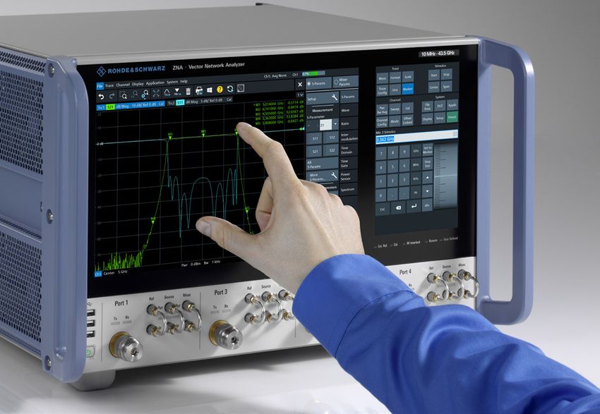
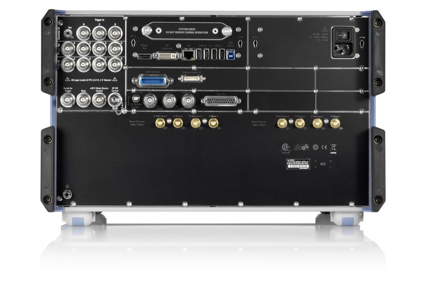
REAR PANEL CONNECTIONS
                                                                   USB control
                                                 LAN port          For remote device control via USB

                                                                                                                   Modular design for
                                                                                                                   easy maintenance
                                                 SSD (removable)                                                   Control PC and power supply
Display ports
►► DisplayPort
►► DVI-D

Internal LO signal output (option)
                                                                                                                   Four USB ports (2.0/3.0)
►► LO source for mmWave converter setups
                                                                                                                   for connecting
   (standard internal LO or optional 2nd
                                                                                                                   ►► Storage media
   internal LO)
                                                                                                                   ►► Keyboard and mouse
►► General-purpose, configurable RF source
                                                                                                                   ►► Calibration units
   up to 26.5 GHz (optional 2nd internal LO)
                                                                                                                   ►► Power sensors

Trigger board (option)                                                                                             User port
                                                                                                                   ►► Digital I/Os
►► Three additional trigger inputs
                                                                                                                   ►► Power supply
►► Four trigger outputs
►► Four connectors for pulse modulator control
►► Ready for trigger (output)
►► Busy (output)
►► RF interlock control (input)

GPIB port

Standard control and sync connectors                                                                               Direct IF access (option)
►► Reference frequency output: 10 MHz, 100 MHz                                                                     ►► I/Os (input/output switchable;
►► Reference frequency input:                                                                                         IF bandwidth OUT: 2 GHz, IN: 1 GHz)
   1 MHz to 50 MHz, 100 MHz, 1 GHz                                                                                 ►► Access to measurement and
►► Trigger input                                                                                                      reference receiver IF of each port

8                                                                                                      Rohde & Schwarz R&S®ZNA Vector Network Analyzer 9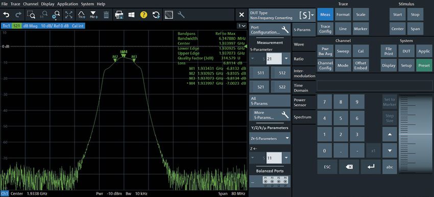
UNIQUE OPERATING CONCEPT WITH
TWO TOUCHSCREENS
Operation using touch gestures easurements, require a vast number of parameters to be
m
Users can operate the R&S®ZNA via two independent set carefully. Working one's way through a host of menus
touchscreens: is time-consuming and error-prone, and the user may
►► Innovative control panel on the right instead of find it difficult to keep track of the overall configuration.
mechanical keys which can wear out over time To e nable users to configure even complex measurement
►► 12.1" touch display on the left for configuring and tasks quickly and accurately, covering all the required
displaying measurements parameters, the R&S®ZNA offers two alternatives.
The dual-screen operating concept offers utmost flexibility 2. All-in-one dialogs – keeping track even of sophisticated setups
in configuring measurements. Touch gestures are used All-in-one dialogs for typical measurements such as
to zoom, move traces and add markers. Traces, channels intermodulation on mixers combine, in a single display,
and diagrams can be dragged and dropped to arrange all key parameters otherwise distributed among several
them in any desired combination. The control panel on the menus. The hardware is configured interactively using
right can, among other things, be used to display macros, graphic elements. Test parameters such as frequencies,
remote control commands and auxiliary tools. power levels and bandwidths are set via pull-down menus
and input fields. Users see all relevant information at a
Analyzer operation is intuitive, which significantly s hortens glance, not missing a single parameter. Measurement
the learning curve and delivers results very quickly. The traces for any desired measurement quantities can then be
user can choose between conventional and guided dragged and dropped to any desired position.
approaches to configuration.
3. Step by step to the desired setup: the DUT-centric wizard
Three alternatives to arrive at the desired setup Another alternative is a step-by-step, DUT-centric
1. Conventional approach approach. In a first step, the user defines the type of DUT
Users can take the conventional approach to configure (e.g. mixer) and its key data (e.g. maximum/minimum
measurements on the R&S®ZNA. From various menus, input power level and frequency ranges). This data can be
they can select the parameters for a desired setup, saved. The wizard then prompts the user, in easy-to-follow
e.g. power parameters, the number of points and the steps, to define the required settings und measurement
measurement type and measurement quantity. However, parameters, using DUT-specific terms (e.g. "Conversion
complex test setups, e.g. for mixer or intermodulation Gain RF to IF" or "Feedthrough LO to IF").
Zoom function
Users can zoom with a simple finger gesture or by dragging the mouse.
The background color of the screen can be configured as desired.
10Control of the R&S®ZNA via touch panel. Users benefit from all-in-one dialogs, which Users can configure measurement tasks conveniently with touch gestures.
provide a clear overview of all key parameters and help to keep track of the overall
measurement configuration.
After all the required settings have been made, the ►► Limit and ripple check with configurable pass/fail
analyzer automatically creates and displays the associated indication
channels and traces. If desired, the user can complete the ►► Statistical trace analysis including maximum, minimum,
measurement configuration by adding system error cor- RMS, peak‑to‑peak and compression point
rection, which is likewise executed step by step. ►► Equation editor for complex trace mathematics
Trace analysis functions Fast switching between instrument setups
A wide variety of trace analysis functions provide a clear With the R&S®ZNA, multiple setups can be kept in
overview of key parameters: memory simultaneously, allowing users to switch quickly
►► Ten markers per trace, including analysis functions and between measurement tasks. This feature is especially
conversion to desired unit advantageous with DUTs that deliver a variety of com-
►► Automatic bandwidth measurement on filters plex results, as it provides a quick overview and simplifies
operation.
DUT-centric measurement configuration
Based on the DUT type, the user is prompted to select and configure the
desired measurements in a s tep-by-step process. The required channels and
traces, e.g. for measuring LO feedthrough, are automatically created.
Rohde & Schwarz R&S®ZNA Vector Network Analyzer 11The R&S®ZNA comes with an extensive range of
hardware options, allowing customized c onfiguration
for the intended use.
TOP-CLASS HARDWARE C
OMPONENTS
The R&S®ZNA comes with an extensive range of hardware options, allowing customized
configuration for the intended use.
Four internal sources of a mixer, making the measurement twice as fast and re-
The R&S®ZNA is available with up to four internal sources ducing trace noise. The optional R&S®ZNA-B8 mmWave
(R&S®ZNA26/43-B3 option, 3rd and 4th internal source for converter LO output makes the analyzer's internal LO
4-port models). The user benefits from a powerful, com- signal (standard LO or second internal LO from 10 MHz
pact system that can even perform intermodulation mea- to 26.5 GHz) available on the rear panel, e.g. for feed-
surements on mixers and receivers with two converter ing mmWave converters connected to the R&S®ZNA 1).
stages. The digitally controlled, phase-coherent and phase- Alternatively, the second LO can be used as a general-
repeatable sources allow phase measurements on mixers purpose RF source, e.g. for external mixers.
and converters without external reference mixers.
Four internal pulse generators and four internal pulse
Direct IF access modulators
When used as inputs, the R&S®ZNA-B26 ports provide Four pulse generators and modulators make it possible to
direct access to the internal IF signal paths. The IF fre- generate pulsed two-tone signals and bidirectional pulsed
quency is selectable with 1 GHz bandwidth, which pro- signals, e.g. for intermodulation measurements on T/R
vides a high degree of freedom for system integration, modules. The pulse generators are enabled with any of the
especially when integrating the analyzer into antenna test following options: R&S®ZNAxx-B4n (internal pulse modu-
systems with external mixers. When used as outputs, the lator for port n) and R&S®ZNA-B91 (trigger and control I/O
R&S®ZNA-B26 ports make it possible to record and ana- board). This means that e.g. the trigger and control I/O
lyze data using external equipment. In that case, 2 GHz of board alone enables use of the internal pulse generators
bandwidth is available. to control internal or external pulse m
odulators (e.g. to
generate pulses with a duration of < 40 ns). Point-in-pulse
Synchronization and trigger capabilities measurements are delivered by the base unit; pulse profile
The R&S®ZNA offers a comprehensive range of synchro- measurements are added with the R&S®ZNA-K7 option.
nization and trigger features such as diverse trigger inputs
and outputs, e.g. for test status indication, definition of Internal combiner
criteria for logical decision-making, RF power shutdown, A switchable internal combiner (R&S®ZNAxx-B213) com-
flexible test sequence control in pulsed measurements, bines the signals from ports 1 and 3 to provide a two-tone
synchronization of external devices, and for timing control signal at port 1, enabling intermodulation m
easurements
during test sequences in production. The R&S®ZNA-B91 and embedded LO group delay measurements (with
option (trigger and control I/O board) acts as an interface R&S®ZNA-K9 option) to be carried out without additional
for the input and output of signals. external equipment.
Second internal LO source and mmWave converter LO output
The second internal LO source (R&S®ZNA-B5 option, for
4-port models) allows two ports to receive signals at dif-
ferent frequencies. This means that two frequencies can 1)
Configuration of the R&S®ZNA-B8 output for use with mmWave converters
be measured simultaneously, e.g. the RF and the IF signal requires the R&S®ZNA-K8 option (mmWave converter support).
12Direct source and receiver access, source monitor (reference The R&S®ZNA‑B161/‑B163 option (direct source monitor
signal) access before or after source step attenuator access) makes the R&S®ZNA even more versatile. It pro-
The R&S®ZNAxx-B16 direct source and receiver access vides direct access to the reference signal, i.e. it allows the
option provides direct access to the source and receiver reference signal to be picked up before the internal source
paths. On the one hand, this yields highest sensitivity as step attenuator. With the step attenuator set to high atten-
the internal coupler can be bypassed, thus avoiding the uation for very small output power levels, picking up the
coupler attenuation, on the other hand, it supports e.g. reference signal before the source step attenuator will pro-
external high-power test setups. vide a reference signal strong enough to deliver low-noise
traces, thus providing high accuracy even with high-gain
DUTs such as satellite and radar modules.
Group delay measurement on a 60 dB gain embedded LO converter
(IFBW = 10 kHz for both measurements).
Blue trace: poor trace noise with the low-level reference signal picked
up after the source step attenuator.
Red trace: minimized trace noise with the reference signal picked up
before the source step attenuator, yielding a high signal-to-noise ratio
at the r eference receiver.
R&S®ZNA‑B161/‑B163 option
¸ZNAxx-B161/ ¸ZNAxx-B2n
¸ZNAxx-B163 Source step attenuator (0 dB to 70 dB/10 dB)
Direct source
monitor access,
–20 dB port 1/ports 1 and 3 Low output power
Source (reference signal
access before source
step attenuator)
Port 1/3
Measurement
receiver
Measurement receiver
Reference
receiver
Reference receiver
¸ZNAxx-B161/-B163 Ref Out
When the R&S®ZNA-B16 reference signal front panel jumper (ports 1 and 3) is reconnected from the standard position (Ref Out) to the
R&S®ZNAxx‑B161/-B163 direct source monitor output, the reference signal will be picked up before the source step attenuator.
Rohde & Schwarz R&S®ZNA Vector Network Analyzer 13UNPRECEDENTED RF QUALITY
Wide dynamic and power sweep range High stability for reliable results
The very high dynamic range of the R&S®ZNA allows the The R&S®ZNA test set and receivers feature excellent
characterization of high-rejection filters. With high output temperature and long-term stability. The instrument's
powers and a wide power sweep range, the instrument magnitude and phase drift are very low, with values of
can analyze the large- and small-signal behavior of ampli- < 0.01 dB/K and < 0.1°/K (typ.). A calibrated R&S®ZNA
fiers in a single sweep: delivers precise measurements over several days without
►► Dynamic range: 147 dB (typ.) 1), > 129 dB (specified, recalibration:
without options) ►► Trace noise of 0.001 dB (RMS, at 1 kHz IFBW)
►► Max. attainable dynamic range: 170 dB (typ.) 2) ►► Temperature stability of 0.01 dB/K and 0.1°/K
►► Electronically controlled power sweep range up to ►► Reliable measurement of high power levels thanks to
100 dB (typ.), interruption-free up to 40 dB (typ.) 0.1 dB receiver compression for 10 dBm power level at
test port
►► High dynamic range of sources due to source step
attenuators up to 70 dB and electronic power sweep
range up to 100 dB
►► Excellent receiver linearity of < 0.05 dB across an
extremely wide range of –50 dBm to 0 dBm
1)
With R&S®ZNAxx‑B3n option.
2)
Requires: maximum output power, R&S®ZNAxx‑B16 option, R&S®ZNAxx‑B3n
option, reversed coupler configuration at receive port, and 1 Hz IF bandwidth.
Dynamic range: at maximum specified output power, without options (blue trace: at
10 Hz IF bandwidth); at maximum specified output power, in reversed coupler mode,
Maximum power sweep range of up to 100 dB. with receiver step attenuator set to 0 dB (red trace: at 1 Hz IF bandwidth).
14HARDWARE OPTIONS
Description Applications and benefits Hardware option
►► Facilitates external test setups for power
Direct source and receiver access 1)
measurements across a wide frequency range
►► With start frequency down to 100 kHz R&S®ZNAxx-B16 2)
►► Reversed coupler configuration increases dynamic
►► Supports reversed coupler configuration
range and reduces system noise figure
►► Short measurement times
R&S®ZNA 4‑port model with up to four internal
►► Flexible-to-configure, compact test setups, R&S®ZNAxx-B3 2) 3)
sources
e.g. for DUTs with two converter stages
2nd internal LO source ►► Fast mixer and converter measurements
►► For simultaneous measurement of two different ►► Very low trace noise with frequency-converting
frequencies (e.g. RF and IF signal on mixers) measurements R&S®ZNA-B5
►► Additional RF source (in combination with ►► General-purpose RF source up to 26.5 GHz
R&S®ZNA-B8 mmWave converter LO output) (e.g. to provide LO signal for external mixers)
►► Reliable multichannel phase and antenna
Four/eight true receivers (no multiplexing) Provided as standard in base unit
measurements
Enhanced flexibility and sensitivity,
Direct IF access, switchable to input or output,
e.g. when used in antenna test systems
with 2 GHz analog IF bandwidth (output) and R&S®ZNA-B26
►► Provides direct access to up to eight phase-
1 GHz analog IF bandwidth (input)
coherent receivers
Four internal pulse generators and four internal pulse ►► For measurements on pulsed signals and for R&S®ZNA-K7
modulators flexible system integration R&S®ZNAxx-B4n 2) 4)
Enhanced trigger and control functions
►► Universal system adaptation and easy system
(three additional trigger inputs, four trigger outputs, R&S®ZNA-B91
integration
four pulse control I/O ports, ready for trigger, busy,
►► High reference frequency for low phase noise
RF interlock control) 5)
►► Generation of low-power stimulus signals
Source step attenuators, 0 dB to 70 dB in 10 dB steps R&S®ZNAxx-B2n 2) 4)
down to –110 dBm
►► Compression-free measurements with input power
Receiver step attenuators, 0 dB to 35 dB in 5 dB steps R&S®ZNAxx-B3n 2) 4)
up to destruction limit of +27 dBm
►► Support of compact mmWave converter setups
Rear panel output for internal LO signal
(2/4-port mmWave converter setups with 2/4-port
(when 2nd internal LO source (R&S®ZNA-B5) R&S®R&S ZNA-B8
R&S®ZNA) without additional external source
is installed, the 2nd LO source is made available)
►► General-purpose RF source up to 26.5 GHz
►► Intermodulation measurements
Switchable internal combiner
►► Embedded LO converter group delay R&S®ZNAxx-B213 2)
Provides a two-tone signal at port 1 6)
measurements (R&S®ZNA-K9 option)
Direct source monitor (reference signal) access
When reconnecting the R&S®ZNAxx-B16 2) reference ►► Low trace noise even with low output power levels
signal front panel jumper to the direct source monitor as typically encountered with high-gain DUTs
R&S®ZNAxx-B161/-B163 2)
output (R&S®ZNAxx-B161/-B163) 2), the signal to the ►► Monitoring of source output power simultaneously
reference receiver can be picked up before the source at source monitor output and test port
step attenuator
1)
Between 100 kHz and 10 MHz, the internal coupler can only be used to a limited extent. Here, external directional components and recalibration are required.
2)
xx designates the R&S®ZNA model (R&S®ZNA26/R&S®ZNA43).
3)
The 2-port R&S®ZNA models come with one RF source as standard, the 4-port R&S®ZNA models with two RF sources.
4)
n designates the port number (1/2/3/4).
5)
1 GHz reference frequency input provided as standard.
6)
4-port R&S®ZNA only.
Rohde & Schwarz R&S®ZNA Vector Network Analyzer 15PRINCIPLE OF OPERATION OF 4-PORT R&S®ZNA
xx designates the R&S®ZNA model (R&S®ZNA26/R&S®ZNA43).
n designates the port number (1/2/3/4).
¸ZNAxx-B16 option: Direct source and receiver access
(frequency extension down to 100 kHz, supports reversed coupler operation)
Port 1 Port 3 Port 2 Port 4
Measurement receiver
Measurement receiver
Measurement receiver
Measurement receiver
Source step attenuator
Source step attenuator
Source step attenuator
Source step attenuator
Reference receiver
Reference receiver
Reference receiver
Reference receiver
¸ZNAxx-B24:
¸ZNAxx-B21:
¸ZNAxx-B23:
¸ZNAxx-B22:
¸ZNAxx-B163: ¸ZNAxx-B31: ¸ZNAxx-B33: ¸ZNAxx-B32: ¸ZNAxx-B34:
Direct source monitor access, Receiver step Receiver step Receiver step Receiver step
ports 1 and 3 attenuator attenuator attenuator attenuator
Internal LO
(standard)
To ports 1 and 3
(to ports 2 and 4)
Ports 2 and 4 To ports 2 and 4
(Path not supported with R&S®ZNA-B5 installed)
To ¸ZNA-B8
(rear panel output)
¸ZNA-B26: ¸ZNA-B26: ¸ZNA-B26:
Direct IF access Direct IF access Direct IF access
To rear panel I/O
To rear panel I/O
To rear panel I/O
¸ZNA-B5: (details on the right) (details on the right) (details on the right)
2nd internal LO source
To port 3
Measurement
Measurement
Measurement
Reference
Reference
Reference
To port 2
To port 4
receiver
receiver
receiver
receiver
receiver
receiver
ADC
ADC
ADC
ADC
ADC
ADC
To port 1
Source 2
¸ZNA-B26:
Direct IF access
Source 4 to port 4 (detailed diagram,
¸ZNAxx-B213: applies to all ports)
Internal combiner Source 1
Measurement
Source 3
Reference
receiver
receiver
to port 2
ADC
ADC
¸ZNAxx-B4n: Control of
Pulse modulator for port n pulse modulators
¸ZNA-B8:
Millimeterwave converter ¸ZNA-B91:
LO (up to 26.5 GHz) Trigger and control I/O board
Source 4
Source 3
Output to
1 ¸ZNA-B91
3+1 trig in, 4 trig out, ¸ZNA-B26:
2
4 pulse control I/Os, Direct IF access,
3
RF interlock control, rear panel I/O ports
4
Ctrl I/Os (busy, ready for trigger)
¸ZNAxx-B3: 4 pulse generators
3rd and 4th
Port 4
Port 3
Port 2
Port 1
internal source
16 Rohde & Schwarz R&S®ZNA Vector Network Analyzer 17PRINCIPLE OF OPERATION OF 2-PORT R&S®ZNA
xx designates the R&S®ZNA model (R&S®ZNA26/R&S®ZNA43).
n designates the port number (1/2/3/4).
¸ZNAxx-B16 option: Direct source and receiver access
(frequency extension down to 100 kHz, supports reversed coupler operation)
Port 1 Port 2
Measurement receiver
Measurement receiver
Source step attenuator
Source step attenuator
Reference receiver
Reference receiver
¸ZNAxx-B21:
¸ZNAxx-B22:
¸ZNAxx-B161: ¸ZNAxx-B31: ¸ZNAxx-B32:
Direct source monitor access, Receiver step Receiver step
port 1 attenuator attenuator
Internal LO
To ports 1 and 2
¸ZNA-B26:
Direct IF access
To rear panel I/O
(details on the right)
Measurement
Reference
¸ZNA-B26:
To port 1
To port 2
receiver
receiver
ADC
ADC
¸ZNAxx-B4n: Direct IF access
Pulse modulator for port n (detailed diagram,
applies to all ports)
Source
Measurement
Reference
receiver
receiver
ADC
ADC
Control of pulse
modulators
¸ZNA-B91:
Trigger and control I/O board
Output to
¸ZNA-B91 1
3+1 trig in, 4 trig out, ¸ZNA-B26:
2
4 pulse control I/Os, Direct IF access,
3
RF interlock control, rear panel I/O ports
4
Ctrl I/Os (busy, ready for trigger)
4 pulse generators
Port 2
Port 1
18 Rohde & Schwarz R&S®ZNA Vector Network Analyzer 19THE RIGHT CALIBRATION FOR EVERY
TEST SCENARIO
The R&S®ZNA offers classic through, open, short, match (TOSM) calibration, which provides a maximum
of precision for S-parameter measurements especially in coaxial test environments. The R&S®ZNA also
supports calibration methods for DUTs in other, specific test environments, e.g. in test fixtures or on wafers,
and for DUTs equipped with different types of connectors at the input and output.
Full calibration with only three standards – faster, simpler, R&S®SMARTerCal – get ready for active device testing
more precise Calibrating the absolute power levels of the sources and
►► Through, reflect, line/line, reflect, line (TRL/LRL) for receivers is indispensable in order to reliably test ampli-
on‑wafer applications, waveguides and coaxial DUTs fiers, mixers and T/R modules. However, this process is
►► Through, reflect, match (TRM) for applications in test time-consuming. The R&S®ZNA uses a special calibration
fixtures and on wafers technique referred to as R&S®SMARTerCal, which radi-
►► Through, short, match (TSM) and through, open, match cally simplifies calibration. R&S®SMARTerCal combines
(TOM) as alternatives to TOSM, for reduced calibration the information gained from system error correction (e.g.
effort TOSM, UOSM) with the information obtained through
absolute power level calibration (wave quantities in terms
Calibration for DUTs using a mix of connectors of amplitude and phase). This means that the absolute
The classic TOSM method does not provide direct calibra- power levels of the sources and receivers are calibrated
tion of test setups for DUTs equipped with different types already during system error correction, taking into account
of connectors at the input and output. The R&S®ZNA offers port mismatch.
two alternatives to provide this type of calibration.
For absolute output power level calibration, the power
UOSM calibration sensor needs to be connected to a test port only once. The
Unknown through, open, short, match (UOSM) calibra- calibration values for all other sources and receivers are
tion is the smartest way to overcome the above problem. derived from the calibration values for that specific test
It involves about the same e ffort as TOSM calibration. A port. This significantly reduces calibration time and effort.
through connection with unknown parameters isrequired,
i.e. a reciprocal (but otherwise more or less arbitrary) two-
port, e.g. a simple and cost-effective adapter.
Adapter removal method
As an alternative, the R&S®ZNA offers classic a dapter
removal calibration. This method is very robust, but
requires considerably more calibration steps.
Straightforward dialogs guide the user step by step through the adapter removal calibration process for calibrating a DUT with a mix of connectors at the input and output.
20Digital automatic level control (ALC) Digital automatic level control (ALC)
The configurable digital ALC sets the source power pre-
DUT
cisely to the target value, using a reference s ignal that can
be derived from any point in the test setup. This means Measurement receiver
that the source power is adjusted, in a minimum of time,
to the output power of a preamplifier in the test setup or to
Digital ALC Reference receiver
the output power of the DUT. Power fluctuations, e.g. due
to drift effects, are eliminated. This provides stable, repro-
ducible power conditions over long test cycles.
Source
Unlike wideband diode detectors, the ALC uses the digi-
tally filtered results delivered by the reference receivers. As
a result, the source power is adjusted to the power of the ALC operation: In the case of a high-power setup with an external preamplifier and a
wanted signal (fundamental) without any distortion other directional coupler, the source power is controlled to match the preamplifier output
wise introduced by harmonics, for example. Users can power. Drift effects can be compensated in this way, making the output power very
configure the ALC parameters, such as the ALC IF band- precise and stable.
width, to achieve the optimum balance of accuracy and
control time.
Absolute power level calibration for sources and receivers The analyzer's excellent receiver linearity of < 0.05 dB
To characterize active DUTs and modules such as m ixers across a wide range from –50 dBm to 0 dBm results in
and amplifiers, it is necessary to calibrate the source high level accuracy even when measuring very small
output power and the receivers to deliver maximum power power levels. The reference and measurement receivers
measurement accuracy. Absolute power level calibration are calibrated at a higher power level that is optimal for the
can be performed for scalar measurements alone (scalar power sensor. The power level is then reduced, while the
corrected) or in combination with system error correction accuracy of the output power is maintained thanks to the
(port-match corrected) using the R&S®SMARTerCal reference receivers' high linearity.
technique. The p arameters for absolute power level
calibration can be independently configured on the
R&S®ZNA, allowing optimal results to be achieved even for
challenging scenarios.
The R&S®SMARTerCal calibration technique combines system error correction with absolute power level correction for sources
and receivers.
Rohde & Schwarz R&S®ZNA Vector Network Analyzer 21Fast embedding/deembedding for impedance matching using AtaiTec in-situ deembedding tool
virtual networks In-situ deembedding (ISD) from AtaiTec is a very
Coaxial and balanced components, such as surface acous- accurate, easy-to-handle and inexpensive tool for
tic wave (SAW) filters used in mobile phone frontends, are on-board and in-fixture calibration. For more
specified together with the networks that match them to information, see www.ataitec.com.
the impedance of the surrounding circuit. The R&S®ZNA
can embed the DUT into virtual matching networks to pro- Calibration equipment
vide realistic conditions by simulating the DUT installed in The R&S®ZN-Z1xx economy calibration kits provide robust
its operational environment. The R&S®ZNA o ffers a choice operation up to 40 GHz. The R&S®ZV‑Z2xx/R&S®ZN‑Z2xx
of predefined matching network topologies. If values of high-end calibration kits are available for more sophisti-
the individual network elements are edited, the R&S®ZNA cated requirements, offering calibration standards from
immediately recalculates the network and embeds the type N through 1.0 mm (110 GHz). These kits achieve very
DUT in the new network in real time. In addition to pre- high calibration accuracy thanks to precision manufactur-
defined topologies, .s2p, .s4p, .s6p and .s8p files can ing combined with S-parameter based characterization of
be read into the R&S®ZNA and used for embedding/ the individual calibration standards.
deembedding.
Automatic calibration units
Enhanced solutions for in-fixture testing Automatic calibration units up to 67 GHz with two or four
In cooperation with partner companies and integrating ports greatly simplify calibration, while reducing operator
complementary third-party tools, the R&S®ZNA was errors and improving calibration repeatability.
enhanced to offer a variety of in-fixture calibration and
expanded (de)embedding functionalities, as well as PCB Calibration of complex setups made easy – the
probing solutions. Calibrate All function
The comprehensive characterization of active DUTs, such
PacketMicro smart fixture deembedding (SFD) tool as amplifiers and converters, usually requires a large
The smart fixture deembedding (SFD) tool from number of parameters and settings to be defined. To cali-
PacketMicro is simple and accurate, and can be used to brate a corresponding number of different channels, us-
extract network parameters for modeling interconnects ers need to invest an enormous amount of time and effort.
such as circuit board traces and vias, connectors, IC pack- This is aggravated by the risk of operator errors as differ-
ages and cables. PacketMicro also offers a wide range of ent calibration standards need to be connected repeat-
PCB probing solutions that support contacting and testing edly. T
he Calibrate All function in the R&S®ZNA avoids
of small geometry devices. For more information, see these drawbacks and lets users achieve reliable results
www.packetmicro.com. with minimum effort. The calibration steps required for
The R&S®ZNA comes with a choice of predefined matching networks whose values can be edited. If values are changed, the
R&S®ZNA will immediately recalculate the network and embed the DUT in the new network in real time.
22R&S®ZN-Z1xx R&S®ZV-Z210 and R&S®ZV-WR10 R&S®ZV-Z2xx and R&S®ZN-Z2xx R&S®ZN-Z52
economy calibration kit high-end calibration kits high-end calibration kits automatic calibration unit
the various channels are combined in the GUI in t abular Results in a minimum of time
form, and the firmware processes these steps for an Besides very short measurement times, the R&S®ZNA
overall calibration procedure covering all channels. Each offers other features that significantly speed up data
calibration standard, calibration unit and power sensor acquisition. The analyzer's high dynamic range of > 129 dB
needs to be connected only once. All the required data (specified) provides a large signal-to-noise r atio to deliver
for the currently c
onnected calibration standard/unit/ accurate measurements, even with high IF bandwidths,
power sensor is collected in the background (e.g. diverse along with short measurement times. During mixer
frequency ranges for intermodulation measurements, measurements, RF and IF signals can be measured simul-
or different sidebands for converter measurements); no taneously, using the second internal LO source. Compared
action is required on the part of the user. This drastically with other instrument concepts, this yields measure
reduces the calibration effort for the overall setup. ment speed as high as that required for non-frequency-
converting S‑parameter measurements. The R&S®ZNA can
pick up measurement data on all of its ports simultane-
ously, a
llowing e.g. a pair of t wo-port DUTs to be tested in
parallel, thereby doubling the throughput.
The Calibrate All function minimizes the calibration effort for the user. It combines all calibrations for a complete setup and
optimizes the calibration process for all channels. Each calibration standard, calibration unit and power sensor needs to be
connected only once.
Rohde & Schwarz R&S®ZNA Vector Network Analyzer 23APPLICATIONS 24
COMPRESSION POINT M
EASUREMENTS
Determining the compression point is essential whenever characterizing active components. With the
R&S®ZNA, compression point measurements can be flexibly combined with S-parameter measurements.
Forward and reverse power sweeps High power measurement accuracy due to vector error
In the case of DUTs with a high output power, e.g. on correction
traveling wave tube (TWT) amplifiers, hysteresis effects Instead of conventional, purely scalar error correction,
often occur that affect determination of the compression compression point analysis on the R&S®ZNA relies exclu-
point. To mitigate these effects, the R&S®ZNA makes it sively on vector error corrected power measurements. This
possible to determine the compression point by perform- delivers precise results even with poorly matched DUTs.
ing ascending and descending power sweeps.
High measurement speed for frequency-converting DUTs
Using the second LO when measuring frequency-
converting DUTs doubles the measurement speed at
the same IF bandwidth without increasing trace noise.
Measurement time is cut in half without any compromise
in accuracy.
DUT-centric measurement configuration
This example shows the configuration of an amplifier measurement using the DUT-centric
approach. The user first selects the type of DUT (e.g. mixer or amplifier) and then, in a
step‑by‑step process, defines the test setup, DUT connections and measurement parameters.
The d esired configuration is generated very quickly while all the necessary parameters are
taken into a ccount. M
easurements on the same DUT and measurements of similar type can
be immediately reproduced based on a user-created DUT library.
Rohde & Schwarz R&S®ZNA Vector Network Analyzer 25INTERMODULATION MEASUREMENTS ON
AMPLIFIERS AND MIXERS
The R&S®ZNA makes it possible to determine the intermodulation characteristics of amplifiers and mixers
fast and with high accuracy.
Frequency sweep with fixed carrier spacing The R&S®ZNA provides the following three types of
intermodulation measurements:
►► Frequency sweep with fixed carrier spacing
►► Frequency sweep with variable carrier spacing
►► Level sweep with fixed carrier spacing
Power
Wide dynamic range and digital ALC for challenging
intermodulation measurements
The R&S®ZNA offers major benefits especially when mea-
suring amplifiers with very small intermodulation products.
Its wide dynamic range and the excellent power h andling
Tone 1, Tone 2, Tone 1, Tone 2, Frequency capacity of its receivers make it possible to measure
swept swept swept swept
low intermodulation distortion within seconds instead
of minutes.
When measuring intermodulation, precise control of
Frequency sweep with variable carrier spacing the powers applied to the DUT inputs is vital. Here, the
R&S®ZNA makes no compromises. Automatic level control
(ALC) combined with system error correction ensures a
precise amplitude for the individual carriers over the entire
frequency range, regardless of the DUT's input reflection
coefficient.
Power
High output power and flexibility
Featuring four independent sources, the R&S®ZNA can
even perform intermodulation measurements on mixers
without requiring an external generator. The analyzer
Tone 1, Tone 2, Tone 2, Frequency delivers high output powers of up to +20 dBm per test
fixed swept swept
port. If this is not sufficient, the R&S®ZNA can flexibly
loop external amplifiers into the signal path and precisely
control them via ALC.
Level sweep with fixed carrier spacing
Power
Power sweep
Tone 1, Tone 2, Frequency
fixed fixed
26DUT-centric approach simplifies configuration of
intermodulation measurements
The DUT-centric approach of the R&S®ZNA supports intui-
tive navigation during intermodulation measurements. To
configure a measurement, the user first selects the type of
DUT and is then guided through a dialog to define the test
setup, the DUT connections, the measurement quantity or
type, e.g. IMx (x = 3, 5, 7, ...) versus frequency, the power
at the DUT input and output, or a spectrum measurement.
The configuration can be completed by a subsequent,
step-by-step user guided calibration procedure.
Comprehensive amplifier character-
ization, including intermodulation
products, IP versus frequency, spectral
measurements, and other quantities.
Power calibration GUI for an amplifier intermodulation measurement.
Rohde & Schwarz R&S®ZNA Vector Network Analyzer 27PULSED MEASUREMENTS – FAST AND
SIMPLE
The R&S®ZNA offers pulse modulators, pulse generators and synchronization I/Os for analyzing active
components under pulsed conditions. Typical DUTs include components and complete T/R modules for
radar a pplications. S‑parameters, input and output powers and intermodulation products can be measured
without any external components to generate RF pulses and synchronize test sequences.
Internal pulse modulators and pulse generators Point-in-pulse measurements
The R&S®ZNA can be equipped with one pulse modulator Short sampling times of 32 ns are achieved for point-
(R&S®ZNAxx-B4n) per port. The pulse modulators can be in-pulse measurements with IF bandwidths ranging up
controlled via external pulse sources or via the four inter- to 30 MHz. In addition to S-parameters, the a bsolute
nal pulse generators. The internal pulse generators can peak power can be determined in amplitude and inter
also be used to control external pulse modulators via the modulation measurements. Flexible trigger functions
trigger board outputs. This allows special modulators for support complex pulsed measurement scenarios and
very short pulses to be integrated, for example. facilitate synchronization of measurements.
Thanks to the test set architecture, once system error cali- Pulse profile analysis versus time with 8 ns resolution
bration has been performed, it remains valid for all types of Equipped with the R&S®ZNA-K7 option, the R&S®ZNA sup-
pulsed measurements – versus frequency, power and time ports pulse profile measurements with a time resolution of
– even if the pulse duty cycle is changed. The R&S®ZNA 8 ns. This technique is suitable for periodic, non-periodic
digital section is designed so that users can configure the and one-shot pulse scenarios.
pulse parameters individually for each port, supported by
a convenient GUI. In addition to double pulses, users can The analyzer provides simultaneous measurement of a
configure arbitrary pulse sequences (i.e. with arbitrary start signal on multiple receivers and for multiple wave quanti-
and stop times for all pulses) in a clearly laid out table. ties. The maximum number of wave quantities/receivers
depends on the IF bandwidth and can vary e.g. between
Measurements versus frequency and power two (at 30 MHz IFBW) and eight (at 1 MHz IFBW). The
The R&S®ZNA supports the common measurement tech- number of wave quantities/receivers can be doubled using
niques for pulsed applications such as point-in-pulse and the R&S®ZNA-B7 option.
pulse profile measurements. For average pulse measure-
ments, which rely on narrow IF bandwidths, the R&S®ZNA
offers highly selective IF digital filters for the carrier signal.
Pulsed measurements
Functions Options
►► Four internal pulse generators with
4 ns time resolution and
The internal pulse generators are enabled with
8 ns minimum pulse width
one of the following options:
Hardware ►► One pulse modulator per port with
R&S®ZNA-B91 (trigger and control I/O board) or
40 ns minimum pulse width
R&S®ZNAxx-B4n (internal pulse modulator, port n)
►► Four trigger inputs
►► Four trigger outputs
►► Up to 30 MHz IF bandwidth
Pulse profile measurements ►► 8 ns time resolution R&S®ZNA-K7
►► 40 ns minimum pulse width
40 ns minimum pulse width
Point-in-pulse measurements R&S®ZNA-K17
(30 MHz IF bandwidth)
28Wideband pulsed measurements with high dynamic range bandwidth. Unique in the R&S®ZNA is a method for aver-
With up to 30 MHz IF bandwidth, the R&S®ZNA provides aging complex values, which allows sensitivity in the order
point-in-pulse and pulse profile measurements on very of –90 dBm to be achieved at an IF bandwidth of 10 MHz,
short pulses. At the same time, the analyzer offers tech- for example.
niques to deliver extremely low-noise traces or achieve a
very high dynamic range despite the wide measurement
Configuration of parameters for pulsed signal measurements.
Pulse profile measurement:
The wideband measurement mode enables single-shot pulse sweeps
without averaging. Averaging (AVG) modes are also available to
achieve either very low trace noise or a very high dynamic range
(i.e. a high pulse on/off ratio) based on vector averaging.
Red trace: AVG mode "Flatten noise".
Blue trace: AVG mode "Reduce noise".
Pulse profile measurement with arbitrary pulse sequences. Pulse
sequences can be measured on multiple receivers simultaneously.
Since the receivers are phase-coherent, they not only measure the
amplitude of a pulse but also its phase with high stability. This allows
the phase deviation of a DUT to be determined very simply and
reliably.
Rohde & Schwarz R&S®ZNA Vector Network Analyzer 29MIXER MEASUREMENTS EASIER
THAN EVER
Fast setup and short measurement times with four internal Conventional conversion loss measurements with a
sources and two internal LOs network analyzer require two measurement steps: first,
The R&S®ZNA four-port model comes with up to the RF input power is measured and then the IF output
four internal sources. Swept LO measurements and power. With two independent LOs for the internal
intermodulation measurements versus frequency on receivers, the R&S®ZNA can perform both measurements
mixers are performed up to ten times faster compared simultaneously, delivering measurement speed twice as
with setups that use external generators. fast as with just one LO while reducing trace noise during
conversion loss and group delay measurements.
High accuracy and easy configuration thanks to
DUT-centric configuration of mixer measurements. R&S®SMARTerCal
The R&S®ZNA determines the return loss and scalar con-
version loss of mixers and converters with high precision
using R&S®SMARTerCal, a special calibration t echnique
that combines system error correction with absolute
power level calibration. It corrects mismatch of the test
ports and mixer; no attenuators are needed to improve
port matching.
Group delay measurement on converter with
Phase measurement on a mixer two-tone signal applied to mixer
LO
RF IF
ΔΦ1 RF IF
LO
ΔΦ2
RF
IF
Two-tone signal obtained with R&S®ZNAxx‑B213 internal combiner or an external
R&S®ZN-Z5x automatic calibration unit R&S®ZN-ZM292 calibration mixer combiner.
30Unique approach for phase and group delay measurements on Relative phase measurements on frequency converters using
converters without LO access vector error correction
The R&S®ZNA offers a special technique for measuring Any receiving system requires a flat amplitude and phase
group delay and relative phase on frequency converters response in order to transmit information smoothly and
in cases where there is no access to the internal LO or the without disruptions. With the R&S®ZNA-K5 option, the
reference frequency. The analyzer uses a two-tone signal R&S®ZNA determines the magnitude and phase for the
to stimulate the DUT. From the phase difference between transmission parameters of mixers and converters with
the carriers at the input and output, the instrument calcu- LO access. This measurement uses the phase-coherent,
lates the group delay and the relative phase. The f requency phase-repeatable synthesizers in the R&S®ZNA in com-
drift and frequency modulation of the DUT's internal LO do bination with a two-port power UOSM (PUOSM) calibra-
not affect the measurement accuracy as long as the fre- tion. The measurement itself does not require a reference
quency deviation lies within the analyzer's IF bandwidth mixer for frequency back-conversion. However, a calibra-
used for the measurement. tion mixer such as the R&S®ZN-ZM292 can be used as
an unknown through for calibration. The measurement is
quick and easy to configure. It delivers the magnitude and
phase for all four system error corrected S-parameters of a
frequency converter, as well as its phase and group delay
and AM/AM and AM/PM conversion.
Results of a converter measurement
including r eturn loss, conversion loss,
phase and group delay.
Frequency-converting measurements
Type of measurement Functions Options
►► Conversion loss of mixer
►► 2nd source for swept LO measurements
►► 3rd and 4th internal source for intermodulation measurements on
mixers and receivers with two converter stages
►► R&S®SMARTerCal for vector error corrected scalar frequency-
Scalar mixer and a rbitrary R&S®ZNA-K4,
converting measurements
frequency-converting measurements R&S®ZNAxx-B3
►► Correction of mismatch on test ports
►► Scalar conversion loss and return loss
►► Isolation measurement: LO → RF and LO → IF
►► Intermodulation products and nth-order intercept point
►► AM/AM conversion
►► 2nd internal LO source for twice the measurement speed
►► Rear panel output for internal LO signal as the 5th source R&S®ZNA-B5,
(when 2nd internal LO source (R&S®ZNA-B5, up to 26.5 GHz) R&S®ZNA-B8
is installed, 2nd LO source is made available)
►► 2‑port power UOSM (PUOSM) for vector error corrected conversion
loss measurements
Vector error corrected converter
►► Forward and reverse conversion loss (magnitude and phase) R&S®ZNA-K5
measurements ►► Absolute/relative group delay
►► AM/AM and AM/PM conversion
►► Calibration mixer R&S®ZN-ZM292
►► Group delay and relative phase
Measurements on frequency R&S®ZNA-K9,
►► 2nd internal LO for twice the measurement speed and for
converters without LO access R&S®ZNA-B5
low trace noise
Rohde & Schwarz R&S®ZNA Vector Network Analyzer 31SPECTRUM ANALYSIS WITH
MULTICHANNEL VIEW
The R&S®ZNA-K1 spectrum analysis function provides a deeper insight into a DUT's behavior where
S‑parameter measurements versus frequency and power are not sufficient.
The FFT-based spectrum analysis function can be used Combined S-parameter and spectrum analysis with marker
to measure a DUT's spurious and harmonics, providing function
short sweep times along with high dynamic range and fine When undesired effects are detected during S-parameter
frequency resolution. It quickly detects undesired signal measurements, the root cause of the problem can be
components (spurious) in converters and T/R modules. identified with a subsequent spectrum analysis, which is
The marker-to-spectrumf unction directly gets to the root performed at the press of a button. A marker is placed
of problems in the event of unexpected S-parameter on the desired frequency, and spectrum analysis around
results, thus providing fast and extremely useful integrated this frequency will deliver conclusive information about
diagnostics. unwanted effects. In addition, a noise marker can be used
to display the n
ormalized noise power in dBm (1 Hz).
Multichannel view of mixer measurements with harmonic and
spurious search
The spectrum analysis function is available on all ports
of the R&S®ZNA. It relies on scalar system error correc-
tion, boosting accuracy and eliminating the influences of
the test setup. In multichannel view, multiple results are
displayed s imultaneously. For example, an S-parameter
measurement can be displayed along with the harmonics
spectrum, or the conversion loss along with the spurious
signals for a mixer.
R&S®ZNA-K1 spectrum analyzer option: amplifier magnitude and phase compression
measurement (at 1 GHz, top), and corresponding harmonic and spurious spectrum. R&S®ZNA-K1 spectrum analyzer option: o utput spectrum of a mixer.
32You can also read