M48-Select Installation Manual
←
→
Page content transcription
If your browser does not render page correctly, please read the page content below
M48-Select
                    Installation Manual

Rev      Date                           Author/s      Checked     Date
1.12   23/04/2021   Jack Wright-Smith                   JA      23/04/2021

                                           Rev.1.12                          1|Page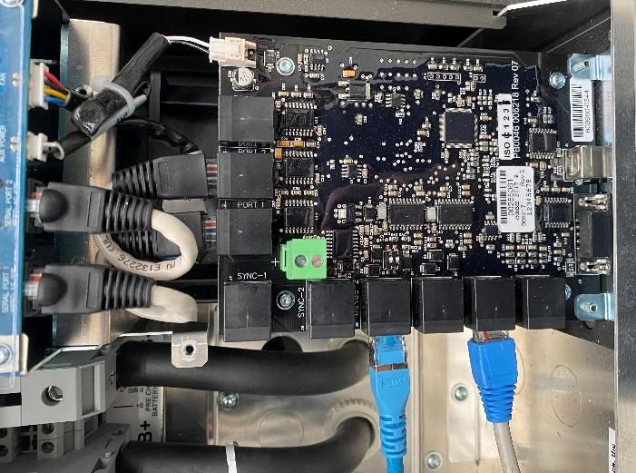
3.4 Placing the batteries inside the M48-Select
 Table of Contents                                                                                        enclosures .................................................................. 20
1.           Introduction........................................................ 3                       3.5 Earthing the batteries to the M48-Select
     1.1     About M48-Select .............................................. 3                            enclosure frame ........................................................ 22

     1.2     Glossary: ............................................................. 3                       3.5.1   Connecting the M48-Select cables to
                                                                                                             the batteries ........................................................... 22
     1.3     Components list: ................................................ 4
                                                                                                          3.6     Wiring SP PRO ................................................... 25
        1.3.1         EVO Power component package .......... 4
                                                                                                             Note: Passthrough from AC Source to AC Loads
     1.4     Required installation tools/material ................. 5
                                                                                                             via SP PRO .............................................................. 25
     1.5     M48-Select Specifications ................................ 7
                                                                                                             3.6.1        Inverter power wiring .............................. 26
        1.5.1         Single Phase .............................................. 7
                                                                                                             3.6.2        Inverter communications wiring ............ 29
        1.5.2         Three Phase ............................................... 8
                                                                                                             3.6.3        Inverter Generator wiring ....................... 30
     ...................................................................................... 8
                                                                                                             3.6.4        Connectiong select.live to SP PRO ....... 31
2.           Safety .................................................................. 9
                                                                                                     4.           First start-up of M48-Select .............................. 33
     2.1     Safety symbols ................................................... 9
                                                                                                          4.1     Pre start-up safety check ................................ 33
     2.2     Emergency safety protocol.............................. 9
                                                                                                          4.2     M48-Select Start-up ......................................... 33
        2.2.1         For all emergencies: ................................. 9
                                                                                                             4.2.1        Batteries ................................................... 33
        2.2.2         For Flooding: .............................................. 9
                                                                                                             4.2.2        Inverter(s) ................................................. 34
        2.2.3         For fires: ...................................................... 9
                                                                                                             4.2.3        select.live ................................................. 34
        2.2.4         Other emergencies not covered: ........... 9
                                                                                                          4.3     Main Switchboard ........................................... 35
     2.3     General safety ................................................. 10
                                                                                                             4.3.1        AC Source ............................................... 35
     2.4     LG Chem battery safety documentation ..... 10
                                                                                                          4.4     System Check .................................................. 35
        2.4.1         Symbols on battery labels ...................... 10
                                                                                                             4.4.1        Check Back-up function ........................ 35
        2.4.2         Safety instructions ................................... 11
                                                                                                     5.           Final assembly .................................................. 36
     2.5     SP PRO Inverter safety documentation ......... 12
                                                                                                          5.1     Inverter access cover...................................... 36
        2.5.1         Who should install this unit...................... 12
                                                                                                          5.2     Close M48-Select enclosure ........................... 36
        2.5.2         Protective Earth connection ................. 12
                                                                                                     6.           Maintenance ................................................... 37
        2.5.3         Multiple Hazardous Energy Sources ...... 12
                                                                                                          6.1     Shutdown procedure ...................................... 37
        2.5.4         Installation ............................................... 13
                                                                                                          6.2     Startup procedure ........................................... 38
        2.5.5         Maintenance .......................................... 13
                                                                                                          6.3     Internal cleaning ............................................. 39
        2.5.6         Inverter may start automatically ........... 13
                                                                                                     7.           Troubleshooting (see website) ....................... 40
        2.5.7  Backup Generator may start
                                                                                                     8.           APPENDICES: .................................................... 41
        automatically......................................................... 13
                                                                                                          8.1 APPENDIX A : M48-SELECT 1-PHASE
        2.5.8         Battery...................................................... 13
                                                                                                          SCHEMATIC (ON GRID) ............................................. 41
3.           M48-Select Installation at user’s site .............. 13
                                                                                                          8.2 APPENDIX B : M48-SELECT 2-phase SCHEMATIC
     3.1     M48-Select installation general information . 13                                             (ON GRID) .................................................................. 42
        3.1.1         Protection against spread of fire .......... 14                                     8.3 APPENDIX C : M48-SELECT 3-phase
     3.2     M48-Select installation near a wall ................ 15                                      SCHEMATIC (ON GRID) ............................................. 43

     3.3     Mounting & Installing the SP PRO(s) ............... 17                                       8.4     APPENDIX D: LG Chem battery details .......... 44

        3.3.1         SP PRO Environmental Considerations . 17                                            8.5     Appendix E: SP PRO communications card . 45

        3.3.2         SP PRO Preparation ................................ 17
        3.3.3         Unpacking SP PRO .................................. 17
        3.3.4         Mounting SP PRO .................................... 18

                                                                                          Rev.1.12                                                                     2|Page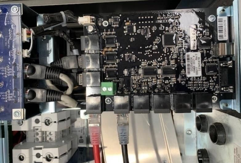
The purpose of this installation manual is to guide and
1. Introduction                                                    advise an installer on how to install an EVO Power M48-
                                                                   Select package safely and securely.
1.1 About M48-Select
                                                                   The installer of the M48-Select must be a suitably
The M48-Select from EVO Power is a compact AC-                     qualified electrician.
Coupled battery package engineered for residential
and commercial power markets, providing high                       As the M48-Select is a plug and play Battery System,
flexibility for solar self-consumption, load shifting and          the installer must complete all the listed installation
complete off grid power applications.                              procedures to complete a M48-Select installation.

The M48-Select incorporates proven and trusted                     This installation manual’s instructions will assist the
hardware with inverters from Selectronic and options from          installer with choosing where the M48-Select will be
18kWh to 180kWh of Lithium Ion Batteries from the world’s          installed at the customer’s location, how they will
leading ESS battery manufacturer, LG Chem.                         place and connect the inverter’s and batteries within
                                                                   the M48-Select, and how they will connect the user’s
M48-Select Features & Benefits                                     Loads and Grid to the M48-Select.
    ✓       Premium quality inverter & battery technology          The battery capacity of the M48-Select is between 5-10
    ✓       Intelligent remote monitoring and control              battery modules for single-phase, while the 2-Phase
            software                                               version requires between 6-10 battery modules, and
                                                                   the 3-Phase version requires 8-10 battery modules. The
    ✓       Flexible storage from 30 to 60kWh
                                                                   amount of battery modules can be increased or
    ✓       Flexible inverter options in single-Phase, 2-Phase     decreased within these specific module ranges, and
            & 3-phase                                              these changes must be completed by an installer.
    ✓       IP20 rated compact indoor enclosure
                                                                   1.2 Glossary:
    ✓       Prewired enclosure with all isolation devices
                                                                   Throughout this manual, the following abbreviations will
  Applications                                                     be used:

        ✓     Off-Grid Power Systems                                     AC – Alternating Current
        ✓     Retrofit to existing Solar Systems                         DC – Direct Current
                                                                         BMS – Battery Management System
        ✓     Residential Solar Self Consumption                         CAN – Controller Area Network
        ✓     Agricultural Power Solution                                PPE – Personal Protective Equipment
        ✓     Commercial & Industrial ESS
        ✓     Utility & Network Grid Service
        ✓     ESS Peak shaving
        ✓     Virtual Power Plant

                                                            Rev.1.12                                             3|Page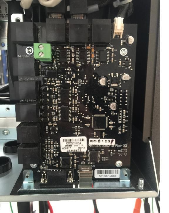
1.3 Components list:

Ensure that all components listed below are delivered to complete the M48-Select installation.
Inspect each component for potential damage during delivery, and if damage is present please report this to your supplier.

Any equipment that is mechanically damaged or damaged in any other way shall not be installed.

Component list:

 Item                  Picture                             Item                     Picture
 M48-Select                                                LG Chem
 enclosure x1                                              EM048126P3S7
 (up to 5 modules)                                         x5-10 for single phase
 or                                                        or
 M48-Select 2 wide                                         x6-10 for 2-phase
 enclosure x1                                              or
 (up to 10 modules)                                        x8-10 for 3-phase

 Selectronic SP PRO                                        EVO Power
 Series II                                                 component package
 x1 for single phase                                       x1
 or
 x2 for 2-phase
 or
 x3 for 3-phase

1.3.1   EVO Power component package
Upon delivery, the M48-Select enclosure will contain a bubble-wrapped package containing a few necessary components
for the M48-Select installation. These package components include:

 SP PRO Expansion                                           SP PRO Tool kit
 Card                                                       + Ferrules
 (1 per inverter)
 + Screws

                                                           Rev.1.12                                           4|Page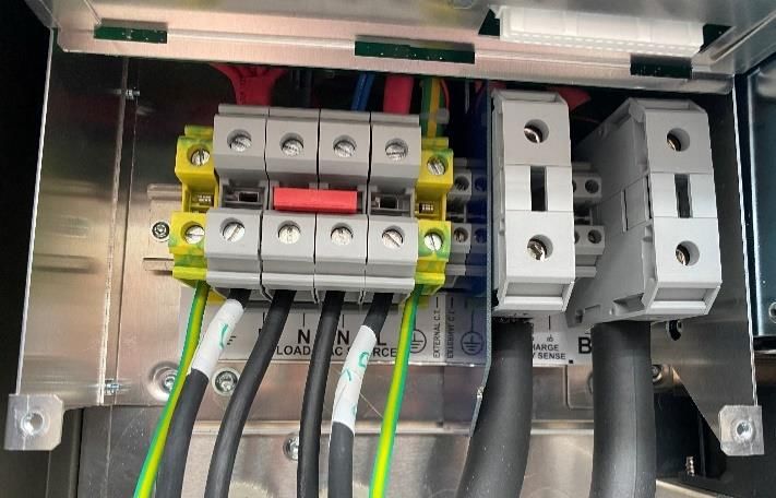
Termination                                                   Know Your SP PRO
 Connectors 2 off (2-                                          display quick
 phase & 3-Phase                                               reference card
 only)

 USB-A to USB-B                                                Ethernet cable for
 Cable                                                         SCert Inverter to SP
                                                               PRO
                                                               (SCert systems only)

 Battery Daisy Chain                                           SP PRO Multiphase
 COMMs                                                         cables
 QTY= #Batts-1                                                 x1 for 2-phase
                                                               x2 for 3-phase

 M48-Select to SP                                              Earthing Screws for
 PRO CAN bus cable                                             Batteries:
                                                                   •    M6x20
                                                                        screw
                                                                   •    Belville
                                                                        Washer
                                                                   •    Serrated
                                                                        Star washer

 Select.live package

1.4 Required installation tools/material

The following tools will be used to complete the M48-Select installation:

 Item                           Description                    Picture
 Personal Protective            Gloves, safety glasses,
 Equipment                      protective footwear

 Hand drive torque wrench       For power cabling into
                                inverter

                                                              Rev.1.12                5|Page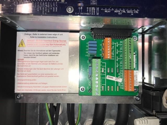
SP PRO drivers               For power cabling into
 (included with EVO Power     inverter
 component package)

 Impact or Clutch Drill       For screwing power
                              cabling into inverter

 Flathead & Phillips          For power cabling into
 driver/screwdriver           Inverter & Main
                              Switchboard

 Scissor Lift Trolley         For lifting inverter(s) &
                              batteries.

 3-wire 0.5mm² Cable for      For plugging Generator       To be provided by the Installer if Generator to be added
 Generator                    into inverter.

 63A Rated AC Power Cable     For cable runs between       To be provided by the Installer
 (according to                main switchboard and
 AS3000/AS3008                inverter.
 requirements)

 Ethernet cable               For cable runs between       To be provided by the Installer if select.live receives internet
 (CAT6E recommended)          System Owner’s Internet      access via ethernet cable
                              Router and select.live.

NOTE: EVO Power recommends the use of lifting apparatus for moving inverters and batteries.

                                                          Rev.1.12                                               6|Page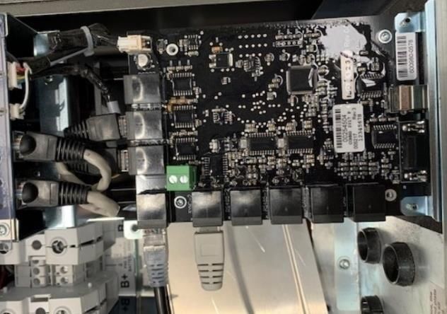
1.5 M48-Select Specifications

1.5.1   Single Phase

                       1.        Useable energy & Nominal Energy is based on beginning of battery life at 25°C and at peak efficiency charge/discharge rate
                       2.        Please refer to the detailed warranty documentation at the EVO Power website www.evopower.com.au
                            All specifications are at 25°C and rated DC input voltage unless otherwise stated, values may be different at higher or lower temperatures.

                            Specifications may be updated without notice so please refer to the EVO Power website for the current information

                                                                                 Rev.1.12                                                                                 7|Page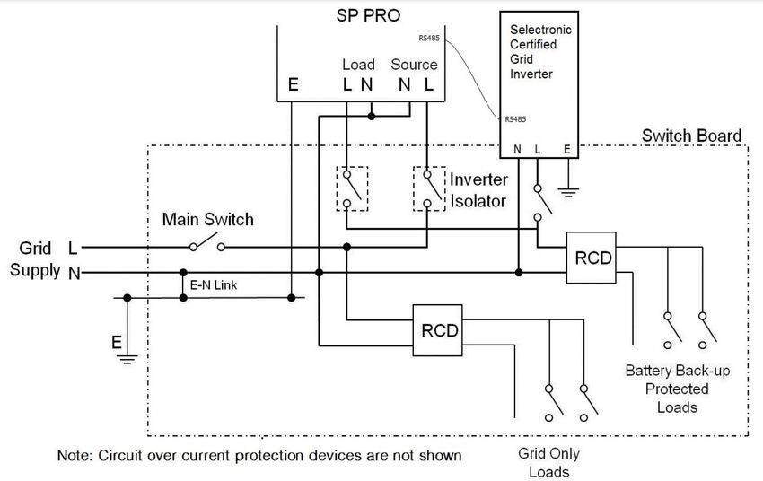
1.5.2   Three Phase

                      1.        Useable energy & Nominal Energy is based on beginning of battery life at 25°C and at peak efficiency charge/discharge rate
                      2.        Please refer to the detailed warranty documentation at the EVO Power website www.evopower.com.au
                           All specifications are at 25°C and rated DC input voltage unless otherwise stated, values may be different at higher or lower temperatures.

                           Specifications may be updated without notice so please refer to the EVO Power website for the current information

                                                                                Rev.1.12                                                                                 8|Page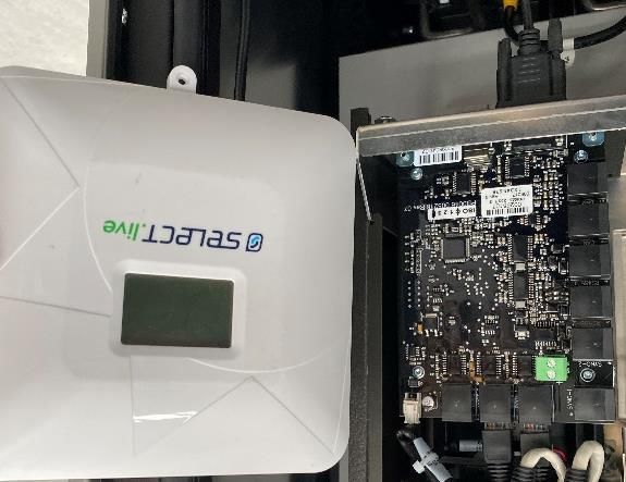
2.2 Emergency safety protocol
2. Safety
                                                                2.2.1           For all emergencies:
2.1 Safety symbols
                                                                        •        Turn OFF DC Isolator/s inside M48-Select enclosure
Throughout the EVO Power M48-Select Installer Manual and                         if safe to do so
M48-Select Labelling, some instructions will have an icon               •        Evacuate the area
next to them.
                                                                        •        Call relevant emergency services in your area
These icons represent the following important hazards or
notifications:
                                                                2.2.2           For Flooding:
                                                                            •     If system is submerged in water, stay out of water
 Icon               Definition                                                    that is connected to submerged system
                    DANGER!
                    An extremely dangerous power                            •     Do not attempt to operate the system after
                    hazard exists during this instruction.                        being submerged in water, even if the system is
                    Take extreme caution during this                              dry
                    process. Failure to do so may                           •     If system has been submerged, product must not
                    cause serious injury or death.                                be used. Dispose of product accordingly

                    CAUTION!
                    This instruction is vital to complete       2.2.3           For fires:
                    the inverter installation safely.
                    Failure to do so may cause an                           •     If safe to do so, use ABC or carbon dioxide
                    issue.                                                        extinguisher to extinguish flames
                                                                            •     Evacuate area
                    MULTIMETER:
                    Use a multimeter to analyse the                         •     Call fire brigade
                    power cables in this section.
                                                                2.2.4           Other emergencies not covered:
                    TORQUE:                                      •      Contact EVO Power
                    Ensure that all screws are
                    thoroughly torqued to the required
                    level in this instruction.

                    INSPECT:
                    Physically inspect what the manual
                    is asking you to look out for.

                    MANUAL:
                    Refer to the manual for all hazards
                    before powering on the M48-Select

                    WAIT:
                    Wait a specified amount of time for
                    the capacitors inside the Inverters
                    to fully discharge

                    WARNING:
                    Refer to the manual for this
                    electrical hazard. Failure to do so
                    could result in serious injury or
                    death.

                                                             Rev.1.12                                                   9|Page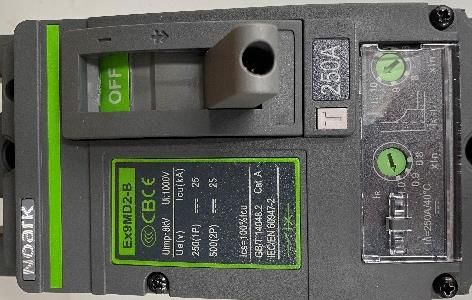
2.3 General safety

            CAUTION!
            All installers and servicers of the EVO Power M48-
            Select system must read and have an extensive
            understanding of all the installation and safety
            procedures listed in this manual.

Only those deemed qualified by EVO Power should provide
repair services for the EVO Power M48-Select system.

If there are any issues or queries during the installation
process, please refer to the troubleshooting section of the
manual in section 6. If the troubleshooting guide does not
help with your problem, please contact EVO Power.                        Symbol   Meaning

            CAUTION!                                                              The voltage of this battery module is
                                                                                  strong enough to cause electric shock.
            Installers and Users may maintain the M48-
            Select. Refer to the maintenance manual
            regarding the safety precautions during                               Keep the battery module away from
            maintenance.                                                          open flame or ignition sources.

            DANGER!
            The M48-Select enclosure weighs up to 150kg                           Wear appropriate personal protective
            without any batteries or inverters inside, and the                    equipment when dealing with the
            M48-Select enclosure can weigh up to 600kg                            battery module.
            after being successfully installed with all battery
            modules.
                                                                                  Keep the battery module away from
            CAUTION!                                                              children.
            The SP PRO Inverters weigh up to 55kg each,
            and each LG Chem battery weighs up to 45kg.
            Ensure that the inverters and batteries are lifted,
                                                                                  The battery module should not be
            mounted and removed with care.                                        disposed of with household waste at the
            It is required to use the mechanical lift to mount                    end of its working life.
            the inverters, and it is recommended to use a
            mechanical lift to mount the batteries within the
            M48-Select enclosure. Follow your local                               Read the manual before installing and
            regulations regarding safe lifting practices.                         operating the battery module.

2.4 LG Chem battery safety documentation                                          The battery module may leak corrosive
                                                                                  electrolyte.
The M48-Select uses the LG Chem EM048126P3S7 series
battery module. The LG Chem safety documentation is
listed below in this section. To access the full instructions for
this module, please refer to the LG Chem P3S series 48V                           The battery module may explode.
Standalone Battery Module Installation Manual.

2.4.1    Symbols on battery labels                                                The battery module is heavy enough to
                                                                                  cause severe injury.
The nameplate and the warning label are attached to the
top of the battery module

The symbols on the battery warning label are described as                         The battery module should be disposed
follows:                                                                          of at a proper facility for
                                                                                  environmentally safe recycling.

                                                                    Rev.1.12                                  10 | P a g e
2.4.2 Safety instructions • Do not impact, pull, drag or step on the battery
module. Do not subject it to any strong force.
For safety reasons, installers are responsible for familiarizing
themselves with the contents of this manual and all • Do not insert foreign objects into any part of the
warnings before performing installation. battery module.
• Do not use cleaning solvents to clean the battery
2.4.2.1 General safety precautions
module.
DANGER!
Failure to observe the precautions described in 2.4.2.3 Response to emergency situations
this section can cause serious injury to persons or While the battery module comprises multiple battery cells
damage to property. that are designed to prevent hazards resulting from failures,
Risks of explosion this cannot guarantee their absolute safety.
• Do not subject the battery module to strong impacts. 2.4.2.3.1 Leaking batteries
• Do not crush or puncture the battery module. If the battery module leaks electrolyte, avoid contact with
the leaking liquid or gas. Electrolyte is corrosive and contact
• Do not dispose of the battery module in a fire. may cause skin irritation and chemical burns. If one is
exposed to the leaked substance, do these actions:
Risks of fire
Inhalation: Evacuate the contaminated area and seek
• Do not expose the battery module to temperatures medical attention immediately.
in excess of 60°C.
Eye contact: Rinse eyes with flowing water for 15 minutes
• Do not place the battery module near a heat and seek medical attention immediately.
source, such as a fireplace.
• Do not expose the battery module to direct sunlight. Skin contact: Wash the affected area thoroughly with soap
and water and seek medical attention immediately.
• Do not allow the battery connectors to touch
conductive objects such as wires. Ingestion: Induce vomiting and seek medical attention
immediately.
Risks of electric shock 2.4.2.3.2 Fire
• Do not disassemble the battery module. In case of a fire, make sure that an ABC or carbon dioxide
• Do not touch the battery module with wet hands. extinguisher is nearby.
• Do not expose the battery module to moisture or
liquids. DANGER!
• Keep the battery module away from children and The battery module may catch fire when heated
animals. above 150°C.
If a fire breaks out where the battery module is installed, do
Risks of damage to the battery module these actions:
• Do not allow the battery module to get in contact 1. Extinguish the fire before the battery module catches fire.
with liquids.
2. If the battery module has caught fire, do not try to
• Do not subject the battery module to high pressures. extinguish the fire. Evacuate people immediately.
• Do not place any objects on top of the battery
module.
DANGER!
2.4.2.2 Battery handling guide If the battery catches fire, it will produce noxious
• Use the battery module only as directed. and poisonous gases. Do not approach.
• Do not use the battery module if it is defective,
appears cracked, broken or otherwise damaged, or 2.4.2.3.3 Wet batteries
fails to operate.
If the battery module is wet or submerged in water, do not
• Do not attempt to open, disassemble, repair, tamper try to access it. Contact EVO Power for technical
with, or modify the battery module. The battery assistance.
module is not user serviceable.
• To protect the battery module and its components 2.4.2.3.4 Damaged batteries
from damage when transporting, handle with care.
Rev.1.12 11 | P a g eDamaged batteries are dangerous and must be handled equipment, and have access to specialist support within
with extreme caution. They are not fit for use and may pose Selectronic to assist with any individual requirements.
a danger to people or property. If the battery module
seems to be damaged, pack it in its original container, and The voltages produced within a power system are
then return it to EVO Power or your distributor. hazardous. Even though the SP PRO may derive its input
from a battery, the extremely high current capability of a
CAUTION! battery bank is hazardous. Additionally, the output and
Damaged batteries may leak electrolyte or input AC voltage in all the SP PRO models is just a hazardous
produce flammable gas. If you suspect such as grid electricity.
damage, immediately contact EVO Power for
advice and information. All AC connections and hazardous DC connections to the
SP PRO must be carried out by a qualified Electrical
2.4.2.3.5 Qualified installers contractor or similar, failure to do so will contravene legal
This manual and the tasks and procedures described herein requirements.
are intended for use by skilled workers only. A skilled worker All DC wiring must be carried out by a person experienced
is defined as a trained and qualified electrician or installer with DC electrical circuits and must understand high current
who has all of the following skills and experience: low voltage circuits. To ensure an efficient system
• Knowledge of the functional principles and operation installation, cable sizing and voltage drop must be
of on-grid systems. understood and the recommendations within this manual
followed.
• Knowledge of the dangers and risks associated with
installing and using electrical devices and EVO Power shall have no obligation as to any equipment
acceptable mitigation methods. which has been improperly installed, stored, or handled, or
• Knowledge of the installation of electrical devices which has not been operated or maintained according to
this manual, nor for any operating mistakes and
• Knowledge of and adherence to this manual and all consequences arising from them.
safety precautions and best practices.
DANGER!
This product is not to be used for Life Support
2.4.2.4 Safety gear equipment
Installers must meet the relevant requirements of
international standards, such as IEC 60364 or domestic
2.5.2 Protective Earth connection
legislation.
DANGER!
It is critical that all protective earth connections
2.5 SP PRO Inverter safety documentation made within the SP PRO us the protective earth
The M48-Select uses the SP PRO inverter. The SP PRO safety terminal. This is the earth terminal that is on the
documentation is listed below in this section. To access the right-hand side of the AC terminals and marked
full instructions for this inverter, please refer to the with an earth symbol enclosed in a circle.
Selectronic Instruction Manual for SP PRO Series 2i
2.5.3 Multiple Hazardous Energy Sources
Interactive Inverter Charger.
DANGER! DANGER! WAIT & WARNING:
If this equipment is used in a manner not specified Hazardous voltages and energy are generated
by the manufacturer as contained in this manual by the SP PRO. They are fed into the SP PRO by
and other operational documents and external wiring from multiple sources and may
Instructions, then the protection provided by the be stored in capacitors after the SP PRO is
equipment may be impaired. switched off and disconnected from external
wiring. If the SP PRO has been powered on, after
2.5.1 Who should install this unit
powering off the SP PRO wait 5 minutes before
While the SP PRO is designed for easy installation and can contacting any of the SP PRO power cabling.
be installed by any suitably qualified person, to maximize Failure to wait 5 minutes could result in an
the performance of the system and tailor the configuration electric shock or electrocution.
of the SP PRO to the specific needs we recommend the use
of a Selectronic Accredited Integrator. These selected
professionals within the industry have been extensively
trained to analyse the system requirements, design ancillary
Rev.1.12 12 | P a g e2.5.4 Installation • Disconnecting a DC power connection (even on
one battery cell) can cause renewable sources to
DANGER!
produce large voltages (much larger than the
• The SP PRO requires adequate ventilation, battery voltage) on battery terminals and DC wiring.
away from hot equipment. Do not obstruct the Such voltages can be lethal. They can also damage
airflow passage of the SP PRO case (top and the SP PRO. Only suitably trained and qualified
bottom). Ensure when installed in an enclosed personnel should disconnect any DC power
space that there is adequate ventilation. connection, including battery cell connections, and
only with suitable procedures and safety
• The SP PRO must be located in a place away
precautions.
from electrolyte and corrosive aerosols.
• System battery voltages of 60 V or greater are to be
• The SP PRO contains arcing contacts so must
treated as a hazardous voltage.
not be located near explosive gas mixtures
such as hydrogen from batteries or diesel
fumes.
3. M48-Select Installation at user’s
2.5.5 Maintenance site
DANGER!
Ensure that all energy sources are isolated before 3.1 M48-Select installation general information
working on connected wiring. A backup generator
CAUTION!
may start, or power may be restored by the SP PRO
To ensure the longevity of the entire system, EVO
at any time. Never work on equipment or
Power require the M48-Select to be installed
investigate a problem without following
under the following requirements:
appropriate safety isolation procedures.
• Indoors
• Ambient operating temperature is between -3°C
2.5.6 Inverter may start automatically to 45°C
DANGER! • Power loads on site do not exceed M48-Select’s
The SP PRO automatically starts and/or restarts and maximum power rating
may restore power at any time. If a fault or
• Surface must be capable of supporting up to
overload is detected the SP PRO will shut down and
600kg of weight
may automatically attempt to restart at varying
intervals of up to several hours. • In an IP20 suitable location
The M48-Select must NOT be installed:
2.5.7 Backup Generator may start automatically
DANGER! • Outdoors or areas exposed to excessive dust
The SP PRO can automatically start and stop a • In direct sunlight (e.g. via glass windows, vents,
backup generator. If a fault or overload caused the etc.)
SP PRO to shutdown then it will automatically • On an angle of more than 2 degrees
attempt to start and restart the backup generator. forwards/backwards & sideways.
2.5.8 Battery • Near marine environments or coastal areas that
may expose the unit to salt mist. Minimum distance
DANGER!
of 1km from coastline.
Batteries are extremely dangerous. Please read the
safety information provided by the battery supplier. • At an altitude higher than 2000m above sea level
• Located near combustible materials
• Batteries are capable of sourcing extremely high
output currents. Short circuit or high overload • In restricted locations as defined for switchboards
currents can be extremely hazardous and cause in AS/NZS 3000
high current arcs, burns and explosions. • Within 600mm of any exit
• Disconnecting a DC power connection (even on • Within 600mm of any vertical side of a window or
one battery cell) can cause dangerous high-energy building ventilation that ventilates a habitable
DC arcs, which can cause serious burns and eject room
hot particles, and can be difficult to extinguish.
Rev.1.12 13 | P a g e• Within 600mm of any hot water unit, air The M48-Select shall be installed in a location such that the
conditioning unit or any other appliance not M48-Select is protected against damage that might
associated with the M48-Select reasonably be expected from the presence of water, high
• Within 900mm below: humidity, dust, vermin or solar radiation (direct sunlight).
o an exit, The installation also needs to comply with safety and
o window, electricity legislation in the relevant state or territory in
Australia.
o building ventilation that ventilates a
habitable room, The M48-Select should be installed in locations that avoid
o hot water unit, localised or general heat sources, such as:
o air conditioning unit, or • Sunlight
o any other appliance not associated with • Generators
the M48-Select • Steam pipes
• In ceiling spaces • Space heaters
• In wall cavities • Uninsulated walls heated from direct sunlight
• On roofs, except where specifically deemed The flow of heated air from any appliance should be
suitable directed way from, and not impact on, the M48-Select.
• Under stairways
Suitable locations for the installation location of the M48-
• Under access walkways Select:
• Under floors of habitable rooms
• Garages
• In an evacuation route or escape route
• Storage rooms
• In habitable rooms
• A dedicated battery system room
• Near combustible materials
NOTE: The ideal installation location of the M48-Select is in a
NEVER place anything on top of the M48-Select enclosure, cool inside area with natural air flow.
including during the installation process.
An M48-Select installed in a corridor, hallway or lobby must
These installation requirements must be fulfilled to maintain have sufficient clearance of no less than 1 metre.
the M48-Select’s warranty.
3.1.1 Protection against spread of fire
See the appliance no-go zone below:
The installation of the M48-Select shall not contribute to, or
propagate a fire in accordance with AS/NZS 3000 Clause
1.5.12.
3.1.1.1 Barrier to habitable rooms
A surface or barrier material is considered suitably non-
combustible if the material is deemed to be not
combustible when tested in accordance with AS 1530.1.
Materials exempt from the need to be tested to AS 1530.1
and considered to be suitably non-combustible are:
• Brick or masonry block
NOTE: The SP PRO and SCERT inverters are considered an
appliance associated with the M48-Select. Selectronic • Concrete
recommend a distance of 150mm between the SP PRO and • Compressed cement sheeting
the M48-Select Enclosure. • Ceramic or terracota tiles
The M48-Select is considered a source of ignition and The material shall have no vents or perforations within the
therefore shall not be installed within a hazardous area as zone required to be covered by the barrier. Any
defined in AS/NZS 3000 Section 7 unless the installation penetration of the barrier that has an internal free space
conforms to AS/NZS 60079.14. For other electrical greater than 5mm diameter shall be sealed with a fire-
installations the M48-Select is considered a source of ignition retardant sealant.
and therefore shall not be installed within hazardous areas
for gas cylinders containing heavier-than-air gases and gas To protect against the spread of fire to habitable rooms,
relieft vent terminals as defined in AS/NZS 3000 Section 4. where the M48-Select is mounted on, or placed against or
near, a surface of a wall or structure shall be a suitably non-
Rev.1.12 14 | P a g ecombustible barrier. If the mounting or nearby surface itself earthquake action requirements for the M48-Select shall be
is not made of a suitably non-combustible material, a non- in accordance with AS 1170.4.
combustible barrier shall be placed between the M48-
Select and the surface of a wall or structure. 3.2 M48-Select installation near a wall
Where the M48-Select is located on the wall, or mounted on CAUTION!
the floor within 300mm of the wall, or structure separating if When placing the M48-Select near a wall, be
from the habitable room, the barrier shall extend: careful of the M48-Select weight of up to 600kg,
as knocking the M48-Select over can cause
• 600mm beyong the vertical sides of the M48-Select serious damage to the M48-Select as well as the
• 900mm above the M48-Select M48-Select’s surroundings. Ensure that the M48-
Select is always upright during the entire
• To the extent of the bottom of the M48-Select
installation process.
Where the top of the M48-Select is within 900mm of the
ceiling or structure above the M48-Select, the ceiling or To allow adequate air flow, as well as easy access to critical
structure surface shall be suitable non-combustible for an breakers inside the M48-Select, the M48-Select must be
area of 600mm past the extremities of the M48-Select. installed within the following measurements:
See the extent of the non-combustible barrier zone below:
• Between wall and back of M48-Select:
From 10mm to 300mm.
3.1.1.2 M48-Select room requirements
Where the M48-Select is installed within a room, it shall be
located so that access to the M48-Select is not obstructed
by the structure of the building, fixtures and fittings within • Between wall and sides of M48-Select:
the room. minimum of 300mm.
The room should be clean, dry & ventilated, and provide & This includes both the Left-Hand side and the Right-
maintain protection against detrimental environmental Hand side of the M48-Select.
conditions and other external factors. In addition, the room
should be selected to minimise likelihood of a build-up of
materials around or on the M48-Select, or an infestation of
insects or vermin, or similar issues occurring that may cause
a hazard.
The size of the room shall allow for sufficient clearance
around the M48-Select to provide safe handling and access
for installation, removal and maintenance.
The minimum unimpeded access on any working side of the
M48-Select enclosure shall be 600mm with doors open.
3.1.1.3 Seismic (earthquake) forces
Depending on location/application, the M48-Select may
need to be installed to withstand seismic (earthquake)
forces.
As the M48-Select is designed to be installed in Australia,
where the M48-Select is installed in or on a building that is
required to be designed for earthquake action, the
Rev.1.12 15 | P a g e• Between wall and front of M48-Select with door open:
minimum of 600mm.
Ensure that there is 600mm of clearance between the
front of the M48-Select and the front door, so that the
M48-Select door can be accessible at all times.
• General clearances from M48-Select to other sources:
According to AS 5139 and BS Best Practices Guide.
Once the M48-Select unit has been put in place it can be
secured from rolling by clicking on the castor wheel brakes,
or by replacing the wheels with the support standoffs with
rubber feet that have been provided in the EVO Power
package.
Note: EVO Power recommend moving the M48-Select
enclosure out of the way when mounting the SP PRO(s).
Rev.1.12 16 | P a g e3.3 Mounting & Installing the SP PRO(s) • Positioned away from heat producing devices such as
generators.
3.3.1 SP PRO Environmental Considerations
• Adequate ventilation, adhering to the minimum
3.3.1.1 Environmental category clearances required for adequate heat dissipation.
The SP PRO is design with an Environmental Category (as Minimum 150 mm clearance from top, bottom and
defined by IEC 62109.1) for “Indoor, unconditioned. The SP sides.
PRO must be protected by a building or enclosure from
• In a covered location away from direct rain. The SP
direct rain, sun, wind-blown dust, fungus and radiation to
PRO has an environmental rating of IP43 which makes
the night sky. The SP PRO must be installed in a dry
it unsuitable for water spray that is greater than 60
environment.
deg from the vertical or greater than 0.7 litres per
3.3.1.2 Pollution degree 2 minute.
The SP PRO is designed to operate in a Pollution Degree 2
• In a location shaded from direct sunlight.
environment. Normally only non-conductive pollution
occurs with occasional temporary conduction due to • Away from any explosive gas.
condensation expected. • Rodent proof.
3.3.1.3 Temperature • In a clean environment away from dust, iron filings,
The SP PRO is designed for an ambient operating workshop pollutants and other small particles.
temperature between -20°C and 60°C, with a storage
• Enough room to remove the cover.
temperature range between –20°C and 70°C. AIR FLOW For
best performance ensure nothing impedes ambient air from • The provision of infrastructure for monitoring - example
being drawn in the bottom of the unit and that hot exit air is data cables The SP PRO should be installed in a
vented away and doesn’t recirculate into the unit. separate area to the battery system (where used). The
Particular attention must be paid when installed inside a battery bank can emit explosive gas (hydrogen) and
cabinet or enclosure. this must be vented outside and away from the SP
3.3.1.4 Clearance from other equipment PRO. The battery system should not be accessible by
the user.
A recommended clearance distance of 150 mm around all
sides, top and bottom. Particular care must be taken when
mounting near other heat producing equipment.
3.3.1.5 Humidity tolerance
The SP PRO is designed to operate in a humidity range of 0 –
99% non condensing.
3.3.1.6 Ingress of particles
The SP PRO has been designed to meet IP rating 43
(Protected against solid objects larger than 1.0 mm /
protected against water falling as a spray at up to 60
degrees from the vertical).
3.3.3 Unpacking SP PRO
3.3.2 SP PRO Preparation Unpack the SP PRO onto a flat surface. When removing the
The selection of a suitable site and good preparation is SP PRO from its packaging carefully inspect for any
essential in gaining optimum performance from the SP PRO. damage that may have occurred in transit. Damage must
be reported to the supplier immediately.
SP PRO Inverter performance is dependent upon the
environmental operating conditions, in particular ambient
temperature and ventilation. Additional safety aspects must
be considered, such as:
• Restrict access to authorised personnel only.
• Consideration of maintenance of ambient
temperatures to ensure performance within product
specification.
Rev.1.12 17 | P a g e3.3.4 Mounting SP PRO CAUTION!
Inspect that all 3 inverters are labelled with their
own individual 1, 2 or 3 label. If the labels are
CAUTION!
missing, damaged or illegible, please contact EVO
EVO Power requires the use of lifting apparatus
Power. It is CRITICAL that the inverters are mounted
for mounting the SP PRO(s).
in their correct positions.
Choose a suitable weight bearing and temperature
CAUTION! resistant surface to mount the SP PRO. Mounting MUST be to
EVO Power has already preconfigured the SP PRO solid timber studs, solid timber, brick, masonry or other load
Inverters to the customers specifications. To bearing wall. DO NOT mount directly to plaster. Max
maintain the inverter’s allocation and temperature is ambient +30°C, max weight is 45 kg. The
configuration, the installer MUST mount the inverters display of the SP PRO should be at eye level. There should
from left to right in the chronological order of 1-2 for be no obstructions to the clear passage of air. Use the 6 x
2-phase systems, and the order of 1-2-3 for 3-phase M8 holes to mount the bracket.
systems.
NOTE: Any wiring via the rear gland plate (attached to
mounting bracket) can be ruffed in before mounting the SP
PRO. EVO Power suggest using the bottom gland plate for
any wiring, and wiring the M48-Select enclosure to the SP
PRO after the SP PRO has been mounted,
Item Description Picture
1. Leave access cover (A) in place. Lift inverter from
underneath whilst stabilising top. Inverter is top heavy and
gloves must be worn. Mount the SP PRO on the mounting
plate by first hooking the top of the inverter over the
projections and lowering it into position. Care should be
taken to observe Pinch Point warning.
A
2. With a T25 torx driver, remove the access cover(A) by
unscrewing the two M5 Torx screws at the bottom of the
SP PRO.
Rev.1.12 18 | P a g e4. The lower gland plate can be removed if required to give
greater access to wiring terminals using T25 torx driver. NB,
side screws need only be loosened. Secure the bottom of
the SP PRO to the mounting plate with two M5 Torx screws.
(A on above diagram)
5. DANGER!
Do not connect any of the wiring to the inverter
at this point, this will be completed in a later
step.
DANGER!
Wiring must only be carried out by suitably
qualified installers and must adhere to all
relevant standards.
Failure to correctly wire the SP PRO can cause severe
damage to the inverter, battery & overall M48-Select system.
Incorrect wiring may also cause the installer and/or
customer to be electrocuted, causing serious injury or death.
6. When all the AC wiring is complete reinstall the terminal
cover and expansion card. Important points
• Failure to fill any holes in rear gland plate (A) or lower
gland plate (B) will reduce IP rating and compromise
thermal design.
7. NOTE: The rear gland plate (circled in red) is screwed to the
mounting bracket. This allows all wiring to be carried out
after the mounting bracket is installed and before the SP
PRO is hung on the mounting bracket.
NOTE: It is important to ensure this screw is
installed.
Complete steps 1-7 for all inverters if the M48-Select is a 2-Phase or 3-Phase configuration.
Rev.1.12 19 | P a g e3.4 Placing the batteries inside the M48-Select
enclosures
After the SP PRO mounting is complete, move the M48-
Select enclosure back into place, and place the batteries
inside the bottom of the M48-Select enclosure.
NOTE: EVO Power recommends the use of lifting apparatus
and Transport Dollys for transporting the batteries to the
M48-Select.
For more information on the battery, please see Appendix
Take care in lifting the batteries, as the batteries weigh up D.
to 45kg each.
Place the batteries inside the M48-Select enclosure from
Bottom to Top. See below where the first battery should be
placed.
CAUTION!
Avoid carrying the
battery exclusively
with the centre
handle, as this can
damage the
battery’s internal
components. If
necessary, always use
two hold points to
carry batteries.
CAUTION!
Ensure that all batteries have their lights off
before placing them inside the M48-Select
enclosure, and that all the DC battery breakers
are switched off inside the M48-Select
enclosure.
CAUTION!
If a battery is accidentally turned on while
placing the battery inside the M48-Select
enclosure, force shutdown of the battery by
holding down the on/off button for 10 seconds
until all the battery’s lights turn off. The on/off
button is seen below in red:
Rev.1.12 20 | P a g eWhen placing each individual battery module, follow the following steps:
Step Description Picture
1. Place the battery next to the M48-
Select enclosure
2. With two people holding opposite
bottom and top corners, lift the
battery into the lowest M48-Select
enclosure battery rack.
3. Slide the battery towards rear until the
sides of the battery are flat against
the M48-Select enclosure frame.
4. Repeat steps 1-3 for all battery
modules, each time placing the
battery as low as possible inside the
M48-Select enclosure battery rack.
Rev.1.12 21 | P a g e3.5 Earthing the batteries to the M48-Select enclosure frame
The battery modules need to be earthed to the M48-Select enclosure frame on both sides. The earthing screws have been
provided by EVO Power in the EVO Power component package. See below for battery earthing instructions:
Step Description Picture
1. Screw in each battery with an M6 bolt,
Belville washer and serrated washer into
the enclosure frame so that the battery is
securely in place.
NOTE: the serrated washer will scratch into
the battery to create an earthing contact
point between the battery and the M48-
Select enclosure frame.
2. The completed battery earthing to the
earthing bar will look like:
3.5.1 Connecting the M48-Select cables to the batteries
The battery’s connection points for the power cables and communication cables are labelled in the diagram below:
Rev.1.12 22 | P a g eComplete the following steps to connect the batteries to the M48-Select:
1. The M48-Select enclosure will have Red and
Black cables protruding from the front-right
side of the enclosure.
The Red (+) and Black (-) battery cables
connect to connectors 5 and 7 respectively
on each battery module.
2. Attach the lowest cables to the lowest
battery module (Red cable to Red battery
terminal, Black cable to Black battery
terminal), and connect all batteries to the
Red and Black cables from lowest to
highest. See an example of all DC
connections:
3. After all Red and Black cables have been
connected, connect the “BMS” labelled
cable to the top battery module in the “4”
port highlighted in red, shown on the battery
diagram.
Rev.1.12 23 | P a g e4. An example of this BMS cable connection is
shown:
4. For all other batteries, daisy chain them
together with the yellow & black short
ethernet cables.
To daisy chain, connect these cables to the
batteries RJ50 port for intra rack
communication cable.
This is shown in red in the diagram:
5. An example of batteries daisy-chained
together is shown:
6. Note: The bottom battery will only have 1
daisy-chain black and yellow cable
connected to it. There is no need to
terminate the last connection.
Rev.1.12 24 | P a g e7. The completed M48-Select cabling should
look similar to this example:
INSPECT:
Ensure that these cables are plugged in and clicked into place securely to avoid communication issues
between the batteries and the inverter.
All M48-Select connections are now in place.
3.6 Wiring SP PRO
This section includes the power and communications wiring for the SP PRO.
The power & communications wiring must be completed for the SP PRO. All internal DC wiring for the M48-Select enclosure
is prewired upon delivery.
Refer to the schematics for the M48-Select found in Appendix A, Appendix B & Appendix C for help with the wiring of the
system.
All inverter power and communications cables must pass through the inverter gland plate holes.
Note: Passthrough from AC Source to AC Loads via SP PRO
After the completion of all M48-Select installation wiring, the SP PRO allows for AC Bypass from the AC source to AC loads
via the SP PRO, even when the SP PRO is not powered on by the batteries. This passthrough will display on the SP PRO’s LED
display, for example:
Rev.1.12 25 | P a g eFor off grid: when the SP PRO isolators are turned off, no power will be supplied to the loads from the batteries, unless a
generator is available.
3.6.1 Inverter power wiring
Connect the power cables into the inverter before the communication cables.
The inverter’s power connection terminals are labelled as follows:
3.6.1.1 Inverter DC wiring
EVO Power have provided 1m lengths of 70mm² cable for the B+
positive and B- negative battery terminals in the SP PRO, which
protrudes from the top of the M48-Select enclosure. The B+ cable has
red heat shrink on the end, while the B- cable does not.
Push this through the SP PRO Glands and cut back the DC cable until
it is at an appropriate length between the SP PRO & M48-Select
enclosure.
Strip back the 70mm² cable insulation by 28mm, and connect the
cables to their respective B+ & B- terminals in the SP PRO.
3.6.1.2 Inverter AC wiring
DANGER!
The SP PRO is overvoltage category III meaning that it must be a fixed installation connected either downstream
of (customer’s side) or directly to the main switchboard.
WARNING: Copper wiring must be used throughout.
The SP PRO does not contain internal circuit breakers of fuses. The AC wiring must be fitted with appropriate fusing or circuit
breakers.
The AC cabling should be sized according to maximum demand through (consumed by the AC Load) and simultaneously
consumed by the SP PRO (consumed by the charging of batteries). The SP PRO is fitted with terminals which are suitable for
accepting up to 35 mm² cables. The SP PRO is rated to 63 A current capacity and must be protected externally with circuit
protection device(s) of no greater than this.
Rev.1.12 26 | P a g eAC wiring should be fed up through the appropriate gland and terminated to the SP PRO. Connect the AC load wiring to
the SP PRO: earth, neutral and active stripped back according to the table below and connected to the AC load
terminals.
Connect the AC source wiring to the SP PRO: earth, neutral and active stripped back according to the table below and
connected to the AC Source terminals.
DANGER!
Multiple Hazardous Energy Sources AC wiring is fed from multiple sources. Care must be taken to ensure that
under no circumstances could a user access or touch wiring, even after opening all circuit breakers
DANGER!
It is critical that all protective earth connections made within the SP PRO use the protective earth
terminal. This is the earth terminal that is on the right hand side of the AC terminals and marked with
a earth symbol enclosed in a circle.
The inverter shall be earthed to the installation’s Earth system. A minimum copper earthing conductor no less than the size in
the table below, shall be used. See the local regulations for further information on earthing conductor size.
Earth the inverter by connecting earth wiring from the switchboard to the inverter Earth terminal. The SP PRO is suitable for
Multiple Earth Neutral systems.
Note: This table is given as a reference only. Please ensure all wiring complies with relevant safety standards.
3.6.1.3 Residual Current Device (RCD) Type Recommendation:
The SP PRO produces a low distortion sine wave output via 50/60 Hz isolation transformer. This topology ensures that the
output is sinusoidal and that there is no DC component associated with the SP PRO AC supply, whether that be feeding a
domestic load or exporting solar to the grid. Standard Type AC RCDs are suitable for use with an SP PRO. Other types of
RCDs may also be used.
3.6.1.4 AC Wiring Preparation
The intended application and use of the SP PRO must be well understood to allow the SP PRO to be appropriately
connected to the installation. How the SP PRO is wired into the switchboard is dependent on whether all the installation’s
loads or only essential loads are to be supplied by the SP PRO for tariff optimisation, self consumption or battery backup.
The below diagram shows AC wiring only and indicates the customer circuits; some of which are battery back-up
protected, some are grid supply only.
Rev.1.12 27 | P a g eAttention must be paid to the Neutral conductor and connection through to the loads. The neutral conductor connecting
to the loads must be maintained such that operation of the inverter isolator would not alter the bonding between Neutral
and Earth.
The Neutral conductor must remain connected through to the loads and particular care should be taken with the
placement of RCDs. These devices open both Active and Neutral conductors thus the SP PRO must be installed on the grid
side of these devices.
Note: This diagram is given as a reference only. Please ensure all wiring complies with relevant safety standards.
DANGER!
The M48-Select MUST be earthed. Earthing the M48-
Select will earth the batteries inside the system,
which will protect the system against faults. The
M48-Select has 1m of 6mm² cable protruding from the top
of the enclosure. Connect this earthing cable to the SP PRO
earth terminals (either Grid or Load side earth) to earth the
M48-Select.
Rev.1.12 28 | P a g eThe final connected AC earthing, Neutral, Grid, Loads and
DC positive and Negative wiring should look like this:
TORQUE:
Ensure all power cables are thoroughly torqued INSPECT:
by hand in this section. (1.5-2Nm for AC and The communications cables are labelled, plug
around 10Nm for DC). Failure to properly torque these cables into the same labelled ports on
these cables will result in power losses and the communications card.
improper contact.
Cable Cable Colour Jacket Colour
SCERT INV Blue Blue RJ45
BATT CAN Grey Blue RJ45
DANGER!
2&3Φ INV SYNC 1&2 Red Clear RJ45
Ensure that all power cables correctly match
3Φ INV SYNC 2&3 Black Clear RJ45
with the inverter terminals. Failure to do so can
cause severe damage to the inverter, battery &
M48-Select. Incorrect wiring may also cause the Single Phase system:
installer and/or customer to be electrocuted,
causing serious injury or death.
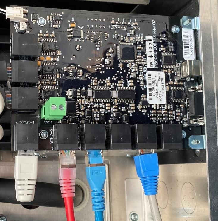
3.6.2 Inverter communications wiring
After all the power cables are secured, connect the
communication cables through the gland holes into their
labelled ports on the communications card as shown:
The BATT CAN cable comes in the EVO Power Package with
the M48-Select. Ensure that the cable has enough length to
reach the SP PRO. Connect this in the BATT CAN port in the
SP PRO comms card, and connect the other end to the SCERT IN
Live V
M48-Select CAN bus RJ45 port:
BATT CAN
Rev.1.12 29 | P a g eThree Phase – Inverter 1 (L1) Three Phase – Inverter 3 (L3)
Terminal Resistor comes
or or
in EVO Power package
Two Phase - Inverter 1 (L1) Two Phase – Inverter 2 (L2)
INV SYNC1
INV SYNC2
INV SYNC1
SCERT IN INV SYNC2
Live V
BATT CAN Terminal Resistor
comes in EVO Power
package
Note: For a complete description of the SP PRO comms
card ports, refer to Appendix E.
3.6.3 Inverter Generator wiring
If the user does not have a generator, skip to section 3.6.4
Three Phase – Inverter 2 (L2)
If the user has a generator, the generator’s controller wiring
must be connected to the 1st inverter. This will be done via
the SP PRO expansion card. The expansion card has been
provided by EVO Power in the EVO Power component
package.
To connect the expansion card to the 1st inverter, push the
card up into the front of the inverter, in front of the power
cabling at the connector interface. Use the T20 torx driver
INV SYNC1 to screw in the two bottom screws of the expansion card
into the inverter, as shown:
INV SYNC2
Connector
Two T20 Torx
screws
For help wiring the user’s generator to the expansion card,
refer to Selectronic’s document TN0025_07: “SP PRO
Generator Controller Wiring Guide”.
Rev.1.12 30 | P a g e3.6.4 Connectiong select.live to SP PRO
The select.live will allow you to monitor your SP PRO system wherever you have an Internet connection.
The M48-Select requires a select.live to be connected to the SP PRO with internet access at all times to maintain the
system’s warranty.
In the EVO Power package is the select.live box, and inside are the following items:
Select.live Wall Mount Plate
Communication Wall Mount Screws
Cable and wall anchors
Double Side Small screw
Mounting Strip
3.6.4.1 Installation of the Select.live
1. Mount your select.live on the wall using the wall mount plate. Attach the wall mount plate to the wall using the
provided double side mounting strip or the wall mount screws & anchors.
The select.live must be mounted on the wall as per the following requirements:
a. The ambient conditions at the mounting location must be suitable for the operation of the Select.live:
i. Operating temperature: -10 to 70°C
ii. Operating humidity: 5 to 95% humidity
b. Within internet access range:
i. The mounting location must have access to your Wi-Fi network if you are using a wireless
connection for Internet access.
ii. The mounting location must be within ethernet cable range of the user’s router if you are using an
ethernet connection for Internet access.
2. Connect your Select.live to the SP PRO inverter, using the supplied communication cable as shown above to
power the device and communicate with SP PRO.
Rev.1.12 31 | P a g e3.6.4.2 Select.live setup for Internet connection:
On the EVO Power configuration form, the user has chosen
to give their M48-Select internet access either via Ethernet
or Wi-Fi.
If Ethernet was selected, then the select.live has already
been pre-configured by EVO Power.
Connect the select.live to the user’s router via an ethernet
cable into the select.live’s ethernet port, and the select.live
will receive internet access. Proceed to step 4.
If Wi-Fi was selected, then the installer must setup the
select.live to connect to the user’s Wi-Fi.
3.6.4.3 Wi-Fi setup for select.live
1. Turn ON the SP PRO. After a minute, you should see
the following message on the screen of your
Select.live
2. From your computer or mobile, connect to the
Select.live using Wi-Fi SSID: “selectronic” with no
password.
3. To setup the Select.live, open a web browser and
enter http://192.168.1.1. The web link will then direct
you to the Select.live setup web interface.
4. Click on the “Setup Wizard” button to auto-detect 5. Once the Select.live Setup Wizard is complete, wait
the SP PRO. Select Wi-Fi connection, then provide approx. 30 seconds and then the following display
your Wi-Fi SSID and password to connect the will appear on the Select.live display screen. Your
Internet. These steps can be seen in the following Select.live is now ready to register for the Select.live
images: Portal using Device ID and Serial.
6. Note down the Device ID and Serial. This will be
used for Select.live Portal registration.
Rev.1.12 32 | P a g e4.2.1 Batteries
Turn on all the battery DC breakers above the batteries. This
will allow the batteries to share a common busbar.
Power the batteries on by pressing the On/Off button on the
top battery module:
To enable remote monitoring & configuring for the user and
installer via the select.live device, please refer to EVO
Power’s “Monitoring & Configuring Manual” and “Owner The top battery will power on with a green light, and every
Monitoring Manual”, which can be found here: other battery will turn on their green light as well.
https://www.evopower.com.au/resources-
support#SupportingDocuments The batteries will then display their position in the battery
array via their blue lights forming a binary code. From top to
The SP PRO power & communication wiring is now bottom the batteries will display their ID number within the
complete. battery array. This should match the Binary lighting shown as
follows;
4. First start-up of M48-Select
4.1 Pre start-up safety check
DANGER!
Before turning any of the batteries on, ensure
that ALL breakers and isolators for the system are
all turned off.
This includes the breakers in the:
• Main Switchboard
o AC Grid If the batteries do not display the correct binary ID’s in
increasing value from top to bottom then hold down the
o AC Loads first batteries ON/OFF button for 10 seconds to reset, then
o Any PV AC or DC isolators/breakers press the top battery module’s On/Off button again.
• M48-Select If problems still persist, please go to the troubleshooting
o Battery breakers x 3-10 (above batteries) guide in section 6.
o Inverter isolators x 1, 2 or 3 (inside glass door After displaying their position in binary, the batteries will rest
of M48-Select enclosure) on the following lights: (Note that more blue lights may be lit
4.2 M48-Select Start-up showing an increased SOC.
Before turning on any of the breakers or isolators on the
M48-Select enclosure and Main Switchboard, check that
the M48-Select wiring is correct first. To do this, check the
battery wiring and then the inverter wiring inside the M48-
Select with the following steps.
Rev.1.12 33 | P a g eYou can also read