Review of Technical Design and Safety Requirements for Vehicle Chargers and Their Infrastructure According to National Swedish and Harmonized ...
←
→
Page content transcription
If your browser does not render page correctly, please read the page content below
Review of Technical Design and Safety Requirements for Vehicle
Chargers and Their Infrastructure According to National Swedish
and Harmonized European Standards
Downloaded from: https://research.chalmers.se, 2021-07-27 08:46 UTC

     Citation for the original published paper (version of record):
     Kersten, A., Rodionov, A., Kuder, M. et al (2021)
     Review of Technical Design and Safety Requirements for Vehicle Chargers and Their
     Infrastructure According to National Swedish and Harmonized European Standards
     Energies, 14(11)
     http://dx.doi.org/10.3390/en14113301

N.B. When citing this work, cite the original published paper.

research.chalmers.se offers the possibility of retrieving research publications produced at Chalmers University of Technology.
It covers all kind of research output: articles, dissertations, conference papers, reports etc. since 2004.
research.chalmers.se is administrated and maintained by Chalmers Library

                                           (article starts on next page)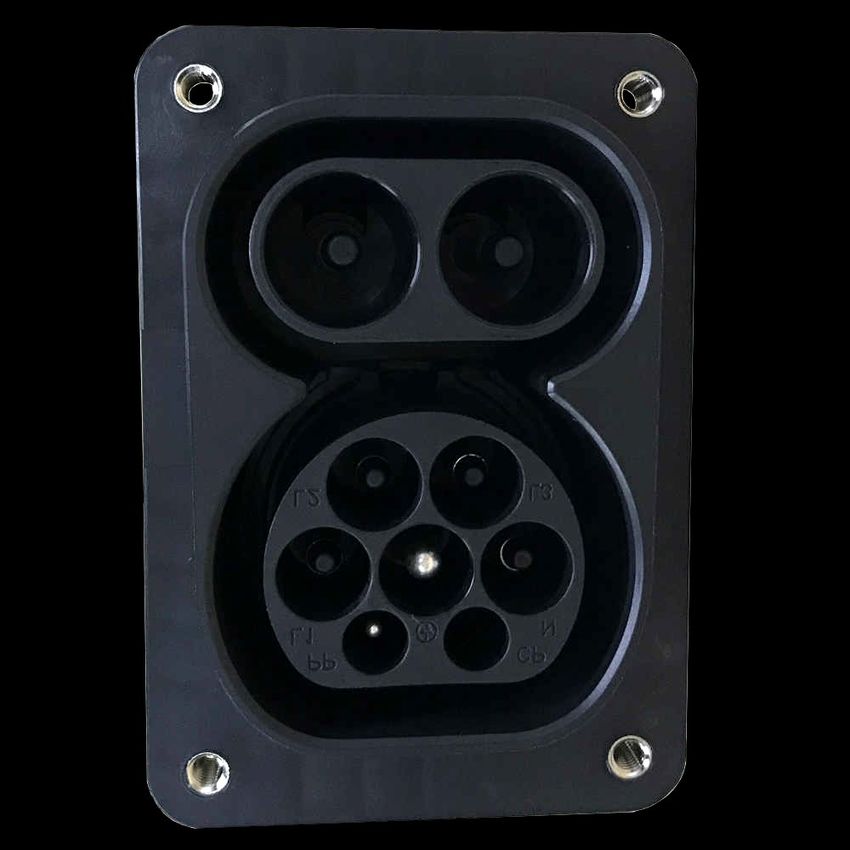
energies
Review
Review of Technical Design and Safety Requirements for
Vehicle Chargers and Their Infrastructure According to
National Swedish and Harmonized European Standards
Anton Kersten 1, *, Artem Rodionov 1 , Manuel Kuder 2 , Thomas Hammarström 1 , Anton Lesnicar 2
and Torbjörn Thiringer 1

                                          1   Department of Electrical Engineering, Chalmers University of Technology, Hörsalsvägen 11,
                                              41258 Gothenburg, Sweden; artem@chalmers.se (A.R.); thomas.hammarstrom@chalmers.se (T.H.);
                                              torbjorn.thiringer@chalmers.se (T.T.)
                                          2   Department of Electrical Engineering, Bundeswehr University Munich, Werner-Heisenberg-Weg 39,
                                              85579 Neubiberg, Germany; manuel.kuder@unibw.de (M.K.); a_lesnicar@yahoo.de (A.L.)
                                          *   Correspondence: kersten@chalmers.se; Tel.: +46-317721305

                                          Abstract: Battery electric vehicles demand a wide variety of charging networks, such as charging
                                          stations and wallboxes, to be set up in the future. The high charging power (typically in the
                                          range of a couple of kW up to a couple of hundred kW) and the possibly long duration of the
                                          charging process (up to more than 24 h) put some special requirements on the electrical infrastructure
                                          of charging stations, sockets, and plugs. This paper gives an overview of the technical design
                                requirements and considerations for vehicle charging stations, sockets, and plugs, including their

                                          infrastructure, according to the Swedish Standard 4364000, “Low-voltage electrical installations—
Citation: Kersten, A.; Rodionov A.;
                                          Rules for design and erection of electrical installations”, and the corresponding harmonized European
Kuder, M.; Hammarström T.;
                                          standards. In detail, the four internationally categorized charging modes are explained and the
Lesnicar A.; Thiringer, T. Review of
                                          preferable charging plugs, including their two-bus communication, according to European Directives
Technical Design and Safety
Requirements for Vehicle Chargers
                                          are shown. The dimensioning of the supply lines and the proper selection of the overcurrent
and Their Infrastructure According to     protection device, the insulation monitor, and the residual current device are described. Furthermore,
National Swedish and Harmonized           a comprehensive overview of the required safety measures, such as the application of an isolation
European Standards. Energies 2021,        transformer or the implementation of an overvoltage protection mechanism, and the limits for
14, 3301. https://doi.org/10.3390/        conducted electromagnetic emissions, such as low-frequency harmonics or high-frequency (150 kHz
en14113301                                to 108 MHz) emissions, are given.

Academic Editor: Woojin Choi              Keywords: battery chargers; battery management systems; charging modes; charging plugs; charging
                                          sockets; charging stations; design standards; electric vehicles; harmonic emissions; harmonized
Received: 30 April 2021
                                          standard; vehicle charging; vehicle safety; voltage drop
Accepted: 30 May 2021
Published: 4 June 2021

Publisher’s Note: MDPI stays neutral
                                          1. Introduction
with regard to jurisdictional claims in
published maps and institutional affil-        The number of deployed electric vehicles has significantly increased throughout the
iations.                                  past few years [1,2], and vehicles’ battery capacities are becoming larger, as well [3]. In the
                                          future, this trend is presumably going to continue [3,4]. Thus, the energy demand and
                                          the power requirements on the electrical grid, due to the charging of electric vehicles,
                                          are steadily rising, as well. Especially, the high charging power (typically in the range
Copyright: © 2021 by the authors.
                                          of a couple of kW up to a couple of hundred kW) and the long charging duration of
Licensee MDPI, Basel, Switzerland.
                                          the charging process (up to more than 24 h) put some special requirements on charging
This article is an open access article
                                          stations’ infrastructure, including charging plugs and charging sockets. Furthermore,
distributed under the terms and           to implement smart charging strategies, such as sharing of the available power among
conditions of the Creative Commons        several vehicles [5], electricity-price triggered charging [6], primary and secondary fre-
Attribution (CC BY) license (https://     quency control [7,8] capability, or utilization as a domestic energy storage system (ESS) [9],
creativecommons.org/licenses/by/          a communication between the vehicle and the charging station/socket is required. The cur-
4.0/).                                    rently available national and international regulations, as well as directives, shall help to

Energies 2021, 14, 3301. https://doi.org/10.3390/en14113301                                              https://www.mdpi.com/journal/energies
Energies 2021, 14, 3301                                                                                            2 of 17

                          set harmonized design and safety requirements for charging stations, sockets, and plugs,
                          including their infrastructure.
                               Despite technically feasible, not all kinds of charger topologies fulfill the necessary
                          safety precautions according to the locally applicable standards. For example, in [10,11],
                          a comprehensive review of various state-of-the-art integrated battery charger topologies is
                          given. These integrated chargers aptly utilize the traction motor’s phase inductances to
                          significantly reduce the required grid filter’s size, which saves space and cost. Although,
                          most of the presented topologies (6 of 8) in [10] are non-isolated converter topologies.
                          In contrast, an isolated converter type breaks the ground loop between a vehicle’s battery
                          and the AC grid and, thus, reduces the risk of unwanted common mode noise, which
                          can compromise the vehicle’s and the user’s safety. Therefore, according to the national
                          Swedish Standard (SS) 4364000 [12], “Low-voltage electrical installations—Rules for design
                          and erection of electrical installations”, only isolated charger types with a permanently
                          installed transformer shall be used for vehicle charging. Based on this simple example, it
                          can be seen that it is quite important to comply with the safety regulations described in the
                          governing standards, despite other technical solutions seem more beneficial in terms of the
                          system’s costs and power density.
                               This paper gives a comprehensive but concise overview about the technical design
                          and safety requirements of conductive charging stations and systems, including their infras-
                          tructure, for battery electric vehicles (BEV) and plug in hybrid vehicles (PHEV) according
                          to the governing Swedish Standard 4364000, “Low-voltage electrical installations—Rules
                          for design and erection of electrical installations”, and the corresponding harmonized Eu-
                          ropean and international standards. In detail, the four internationally categorized charging
                          modes are explained and the preferable charging plugs, including their two-bus commu-
                          nication, according to European Directives are shown. The dimensioning of the supply
                          lines and the proper selection of the overcurrent protection device, the insulation monitor,
                          and the residual current device are described. Furthermore, a comprehensive overview
                          of the required safety measures, such as the application of an isolation transformer or the
                          implementation of an overvoltage protection mechanism, and the limits for conducted
                          electromagnetic emissions, such as low-frequency harmonics or high-frequency (150 kHz
                          to 108 MHz) emissions, are given.
                               Within the frame of this paper, all numbered European Standards carry the preced-
                          ing abbreviation EN (European Norm, as literally translated from French/German) and
                          standards issued by the International Electrotechnical Commission are abbreviated as IEC.
                          Furthermore, harmonized standards are abbreviated by the national Swedish Standard
                          abbreviation SS and the international standard’s abbreviation, for example, SS EN, SS IEC, etc.
                               So far, wireless/inductive charging, as, for example, described in [13,14], is not yet
                          covered in the SS 4364000 and, thus, is not considered within the scope of this paper.

                          2. Charging Modes
                               As described in [15], there are four different charging modes for BEVs and PHEVs,
                          which are illustrated in Figure 1. In general, charging mode 1, 2 and 3 utilize an on-board
                          charger (OBC), which is supplied by the AC mains or an AC charging station. Charging
                          mode 4 instead employs a DC charging station, and it is often referred to as fast charging.
                          Furthermore, charging mode 3 and charging mode 4 require a special and permanently
                          installed electrical infrastructure, including a communication between the charging station
                          and the vehicle. In contrast, charging mode 1 can be realized by a direct connection between
                          a domestic power socket and the OBC without requiring any additional communication
                          infrastructure between the mains and the vehicle. Similar to charging mode 1, charging
                          mode 2 can utilize a domestic power socket, but some additional equipment is needed.
                          During the charging process, independent of the charging mode, the required battery
                          management system (BMS) shall ensure that each of the individual battery cells are evenly
                          charged (typically, using passive balancing [16,17]) and that the maximum battery voltage
                          limit is not exceeded. Moreover, the BMS can also request to reduce the reference current,
Energies 2021, 14, 3301 3 of 17
which is controlled by the OBC or the DC charging station, to ensure not to exceed the
maximum allowable battery temperature. In the following, the individual charging modes
are explained in detail.
Common AC Common AC
power socket power socket
BMS 230V/400V max 16A BMS 230V/400V max 32A
Battery OBC Battery OBC EVSE
Communication Charging current Communication Charging current
(a) (b)
DC charging station
AC charging station 400V to 1000V
BMS 230V/400V max 63A BMS max 400A
Battery OBC Battery
EVSE
Communication Charging current Communication Charging current
(c) (d)
Figure 1. Illustration of the four charging modes as described in [12]. (a) Charging mode 1. (b) Charging mode 2.
(c) Charging mode 3. (d) Charging mode 4.
As already mentioned, charging mode 1 consists of a direct connection between the
electric vehicle and the AC mains, 230 V/400 V with a maximum allowable current rating
not exceeding 16 A. Typically, a common domestic (single-phase) AC socket, without any
additional safety systems, can be used to supply the vehicle. The OBC rectifies the AC
voltage to charge the battery. Unless unplugged, the lead is always live when using
charging mode 1. Normally, charging mode 1 is only used for light vehicles, such as electric
bikes or scooters with a low-voltage (≤60 V) battery system and a maximum charging
power of a couple of hundred watts. In some European countries, charging mode 1 is
subject to restrictions in public areas, and it is not allowed in Israel, the United Kingdom,
and the United States [18]. According to [12], charging mode 1 is usually not supported for
electric passenger cars.
Unlike charging mode 1, charging mode 2 requires some additional electrical con-
trol/safety equipment, referred to as electric vehicle supply equipment (EVSE). The EVSE
is placed between the OBC and the AC power socket, typically integrated in the charging
cable. Via a two-wire communication bus and a control unit, the EVSE can set the reference
charging current for the OBC. Additionally, the EVSE monitors the charging process. When
the battery is fully charged, the EVSE disconnects the OBC from the AC mains, referred to
as safety lock-out. Furthermore, the EVSE can detect hardware faults, such as a faulty cable
plug connection or an external short-circuit fault. For charging mode 2, both domestic
(single-phase) and industrial (three-phase) AC sockets with a current rating up to 32 A can
be used. Consequently, the maximum three-phase charging power, assuming unity power
factor (cos ( ϕ) ≈ 1) [19], according to
PCharging = 3 · IB · VPhase,rat · cos ( ϕ) , (1)
becomes
PCharging = 3 × 32 A × 230 V × 1 ≈ 22.1 kW . (2)
Nonetheless, only AC sockets designated for charging should be used, since the
charging process can occupy the available power capability of the grid’s connection point
for several hours, as listed in Table 1. Furthermore, domestic (single-phase) AC sockets can
rapidly wear out when loaded over a long period with rated current [20]. Thus, chargingEnergies 2021, 14, 3301 4 of 17
a vehicle from a domestic AC socket, which is not designated for charging, should be
considered only as “emergency charging”.
Table 1. Charging time of a BEV with a battery capacity of about 60 kWh with respect to the charging type.
Charging Type Power Rating [kW] Charging Time [h]
Single-phase—10 A 2.3 kW 26.1
Single-phase—16 A 3.7 kW 16.2
Three-phase—16 A 11 kW 5.5
Three-phase—32 A 22 kW 2.7
Three-phase—63 A 44 kW 1.4
DC fast charging 50 kW 1.2
DC fast charging 120 kW 0.5
Charging mode 3 requires that the BEV or PHEV is charged via an AC charging
station, which is permanently connected to the grid. The EVSE, including the control
and safety functions, is directly integrated into the charging station. Normally, wall-
boxes, charging columns, commercial charging points and all automatic AC charging
systems (with an integrated EVSE) are considered as AC charging stations in accordance
with charging mode 3. The current rating of the charging station can be up to 63 A [12].
Consequently, the maximum three-phase charging power, assuming unity power factor
(cos ( ϕ) ≈ 1) [19] , according to
PCharging = 3 · IB · VPhase,rat · cos ( ϕ) , (3)
becomes
PCharging = 3 × 63 A × 230 V × 1 ≈ 43.5 kW . (4)
Since the charging power for charging mode 3 can be significantly increased in com-
parison to charging mode 1 and charging mode 2, specially designated AC sockets and
charging plugs should be used, as further explained in Section 3. Charging mode 3
should be preferably used for home charging stations and, according to the EU directive
2014/94 [21], it should be employed at public charging stations.
Charging mode 4 is the only mode that utilizes DC current. As illustrated in Figure 1d, no
OBC is required, since there is a direct connection between the charging station and the
vehicle’s battery. The power electronics circuitry, which is integrated in the DC charg-
ing station, can adjust the output voltage to control the DC charging current. Typically,
the output voltage can be adjusted up to 1000 V and the charging current can be up to
400 A. Thus, a charging station according to charging mode 4 can theoretically achieve a
charging power of a couple of hundred kW [22]. However, the battery’s charging efficiency
is significantly decreased when using such a high charging power [23]; thus, the BMS has
to constrain the maximum charging power to comply with the temperature limit of the
battery system. Therefore, DC charging stations for passenger vehicles are often operated
with a continuous power from 40 kW to 130 kW.
3. Charging Plugs and Socket-Outlets
The high charging power, the possibly long duration of the charging process (see
Table 1) put some special requirements on the electrical infrastructure, including the charg-
ing plugs and the charging sockets. Furthermore, with respect to the project IEEE 2030 [24],
“Guide for Smart Grid Interoperability of Energy Technology and Information Technol-
ogy Operation with the Electric Power System (EPS), End-Use Applications, and Loads”,
the charging plugs and sockets should preferably comprise a communication interface and
the charging infrastructure should allow for bidirectional power flow capability.
For example, domestic (single-phase) wall-mounted AC sockets or plugs according to
the SS-428-08-34 [25] or the internationally harmonized IEC standard SS-IEC-60884-1 [26]Energies 2021, 14, 3301 5 of 17
can rapidly wear out when loaded over a long time with rated current [20]. In con-
trast, industrial (three-phase) socket-outlets according to the SS-EN-60309-1 [27] and the
SS-EN-60309-2 [28] can be fully utilized, but the current rating shall not exceed 32 A ac-
cording to charging mode 2 [12]. Nonetheless, the charging process can easily occupy the
full current capability of the grid’s connection point for a long duration (see Table 1), while
no other loads can be used. Thus, it is often reasonable to adjust/reduce the charging
current accordingly or to balance the available power among all loads. However, both
domestic and industrial AC sockets do not provide any communication between the ve-
hicle’s OBC and the AC socket to adjust the reference current for the charging process.
Therefore, to adjust/reduce the charging current, at least some additional EVSE would be
required when charging a vehicle from a domestic or industrial socket-outlet (charging
mode 2). For example, Figure 2 shows a single-phase charging cable from Deltaco [29] with
a SchuKo and a Type 2 connector including an in-line integrated EVSE, which includes a
communication interface to adjust the charging current’s reference between 10 A and 16 A.
Figure 2. Single-phase charging cable with SchuKo and Type 2 connector including in-line integrated
EVSE to adjust the charging current reference between 10 A and 16 A from Deltaco [29].
To achieve higher charging power levels (>>20 kW), as desired for public charging sta-
tions, the charging plugs and sockets according to the standard series SS-EN-62196 [30–32]
(harmonized European standard) shall be used, which is in accordance with the interna-
tional standard series IEC-62196, “Plugs, socket-outlets, vehicle connectors and vehicle
inlets—Conductive charging of electric vehicles”. The plugs and socket-outlets according
to the standard series SS-EN 62196 are not only rated for high current levels, these also com-
prise an interface for a two-wire bus communication, referred to as vehicle to grid (V2G)
communication interface in accordance with the SS-EN-ISO 15118-1 [33]. With the help of
the communication interface, smart charging strategies can be easily realized. For example,
the available power of a public charging station could be evenly distributed among all
vehicles [5] or a vehicle is only charged if the electricity price is below a certain threshold [6].
Moreover, considering the IEEE Std 1547 [34], “IEEE Standard for Interconnection and
Interoperability of Distributed Energy Resources with Associated Electric Power Systems
Interfaces”, vehicles’ charging infrastructure can provide also ancillary service functions for
distribution or transmission system operators, such as intentional local islanding possibil-
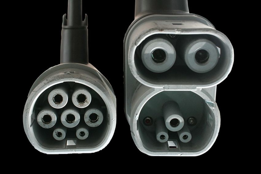
ity [9,35] or primary and secondary frequency control capability [7,8]. The Type 2 charging
plug according to the standard SS-EN-62196-2 [31] can be seen in Figure 3a. It should be
used for three-phase AC charging according to charging mode 3, but it is not limited to
it. The Combo 2 charging plug according to standard SS-EN-62196-3 [32] can be seen in
Figure 3b. It should be used for DC charging according to charging mode 4. With respect
to the harmonized European standard series EN 62196, the EU directive 2014/94 [21] statesEnergies 2021, 14, 3301 6 of 17
that any public charging station should comprise at least one charging plug of Type 2 and
one of type Combo 2. The combined charging socket of Type 2 and Combo 2 (CCS 2),
manufactured by Khons Technology, can be seen in Figure 3c. This combined charging
system (CCS) is commonly abbreviated as CCS 2 and it should be preferably used for
EVs in Sweden and the European Union. As can be seen from Figure 3c, the CCS 2 socket
comprises a two wire communication bus (PP and CP), a normal three-phase connection
interface (L1, L2, L3, N, and PE), and a DC connection interface (DC+ and DC-). Both,
the Type 2 and the Combo 2, as well as the CCS 2, charging plugs and sockets are recog-
nized in North America under the recommended practice of the SAE J3068 [36], “Electric
Vehicle Power Transfer System Using a Three-Phase Capable Coupler”.
1 PP
4
1 2 2 CP
3 L1
3 5
4 PE
6 7
5 N
6 L2
8 9 7 L3
8 DC-
9 DC+
(a) (b) (c)
Figure 3. Charging plugs [37]: (a) Type 2 according to the SS-EN-62196-2 [31] and (b) Combo 2 according to the
SS-EN-62196-3 [32]. Charging socket [38]: (c) CCS 2 socket-outlet from Khons Technology allowing for charging via
a Type 2 or a Combo 2 plug according to the SS-EN-62196-3 [32].
Another (globally) popular charging system is the CHAdeMO system [39,40] (for
DC charging), which stands for “CHArge de MOve”. However, especially due the EU
directive 2014/94 [21], the CCS 2 is becoming dominant in Europe in comparison to the
CHAdeMO system.
Furthermore, while using charging mode 3 or charging mode 4, an electrical or
mechanical mechanism, sometimes referred to as latch-locking, should be used to lock the
charging plug [12]. This measure should ensure a low electrical contact resistance.
4. Overcurrent Protection and Cable Dimensioning
The approximated time durations to fully charge a BEV with a nominal battery
capacity of about 60 kWh with respect to different charging types are given in Table 1. For
example, when using single-phase charging with a maximum current rating of about 10 A
or 16 A, the required charging time can be up to 26.1 h or 16.2 h, respectively. Thus, when
loading the electrical mains for such a long time with the rated current, it is important to
properly dimension the electrical infrastructure, such as plugs and socket-outlets, including
the cables and the overcurrent protection. Therefore, this section gives a short description
on how to dimension the cables’ conductor size and how to select the corresponding
overcurrent protection device for a charging application.
In general, according to [12], any power-socket designated for charging should be
placed as close as possible to the vehicle’s parking spot. Thereby, the voltage drop (losses)
along the cable should be kept as small as possible and the proper functioning of any
overcurrent protection device should be ensured.Energies 2021, 14, 3301 7 of 17
4.1. Selection of Overcurrent Protection Device
When designing the electrical installation for a charging station/socket, it is reasonable
to start with the selection of the overcurrent protection device. As described in [12], any
over-current protection device should satisfy the following relation
IB ≤ In ≤ Iz , (5)
with IB being the rated current of the load circuitry and In being the nominal current of
the selected circuit breaker or fuse. The conductors’ nominal current capability Iz can be
described according to
Iz = Iz,0 · kT · kM , (6)
with Iz,0 being the conductors’ current capability for a certain cross-sectional area under
consideration of the method of installation. The coefficients kT (temperature) and kM
(grouping) should be used to correct the conductors’ current rating relative to the ambient
temperature and the number of touching multi-core cables or groups of single-core cables,
respectively. Moreover, as further described in [12], the overcurrent protection device
should also satisfy the relation
I2 ≤ 1.45 · Iz , (7)
with I2 being the current value that ensures a proper functioning of the overcurrent protec-
tion device.
For example, a typical tripping characteristic of a type C miniature circuit breaker,
according to the SS-EN 60898-1 [41], with a nominal current rating of In can be seen in
Figure 4.
10000
1000
100
10
1
0.1
0.01
1 2 3 4 5 10
Figure 4. Tripping characteristic of type C miniature circuit breaker: time till trip versus current as multiple of nominal
current I/In .
Typically, a miniature circuit breaker comprises two tripping mechanisms. A thermal
and an electromagnetic mechanism are used for the protection against overcurrents or
short-circuit faults, respectively. At the left-hand side of the thermal release zone in Figure 4 no
overcurrent fault would be detected as long as the relative overcurrent I/In is less than
1.13. Nonetheless, if the relative overcurrent I/In exceeds 1.45, an overcurrent fault is
certainly detected by the thermal tripping mechanism; thus, the condition in (7) would
always be satisfied as long the current capability Iz was chosen in accordance with (5).
In comparison to the thermal release zone, the electromagnetic release zone describes
the protection against short-circuit faults. As can be seen, a short circuit fault can be
detected, if the relative overcurrent I/In is higher than 5 and lower than 10 (EM release
zone of type C circuit breaker). Moreover, for high short circuit currents (I/In ≥ 10),Energies 2021, 14, 3301 8 of 17
the time till tripping is almost instantaneously. The boundaries of the EM release zone are
dependent on the circuit breaker’s characteristic (e.g., A, B, C, etc.) and should be chosen
in accordance with the load. For instance, the high starting current of a electric line-start
machine [42] shall not be misinterpreted as a short-circuit fault; thus, the lower boundary of
the EM release should be accordingly chosen (typically, type C). For a charging application,
the inrush currents can be easily limited by pre-charging resistors or soft starters. Thus,
for charging applications, it is often sufficient to select a type B circuit breaker (EM release
zone: 3 ≤ I/In ≤ 5).
4.2. Placement of Overcurrent Protection Device
Normally, parallel loads can be operated at the same power socket as long as these are
only consuming electrical energy. However, if power-consuming and power-generating
devices are connected in parallel at the same connection point, the proper functioning
of its closest over-current protection device might not be ensured anymore. Despite
vehicle charging stations/sockets are mainly considered as power-consumers, these can
also be utilized as energy-storages. In this way, a fleet of electric vehicles can possibly
inject active power into the power-system to assist the primary or secondary frequency
control functionality [7,8], and, thereby, the power-system’s frequency can be maintained.
Furthermore, a vehicle’s battery could also be used as a domestic energy storage [9].
Therefore, as described in [12], the grouping factor kM in (5) shall be equal to one for
any supply line feeding an individual charging point. This means that each designated
charging point/socket must be individually protected against overcurrent and short circuit
faults. In contrast, the grouping factor kM for the main line, supplying the distribution
network of a charging station, can be reduced if a proper load control management system
is used [12].
4.3. Permissible Voltage Drop along the Supply Line
According to [12], the maximum permissible voltage drop along the power supply
line, from the mains distribution to the load, corresponds to 5%. As described in [12],
the relative voltage drop VDrop,% [%] along the supply line can be calculated according to
VDrop
VDrop,% = 100% · , (8)
VPhase,rat
with VDrop being the absolute voltage drop at rated load operation, and VPhase,rat being
the nominal phase voltage of the mains, corresponding to 230 V in Sweden [43]. Further,
the absolute voltage at rated load, as described in [12], can be calculated according to
L
VDrop = b ρT cos( ϕ) + λL sin ( ϕ) IB , (9)
A
as further explained in the following. As before mentioned, the rated load operation of
the supply line should be considered when conducting the line’s rated load current IB [A]
with the corresponding power factor angle ϕ [rad s−1 ]. For vehicle charging applications,
it can be assumed that modern power electronic converters can achieve a power factor
close to unity [44,45]. The dimensionless coefficient b corresponds to 2 or 1 for a single or
three-phase system, respectively. The variables L [m] and A [mm2 ] describe the conductors’
length and their cross-sectional area, respectively. The relative resistivity ρT [Ω mm2 m−1 ]
of the supply line’s conductors is dependent on the operating temperature T [°C] and its
material, such as copper or aluminum, which can be described as
ρT = ρ0 [1 + α( T − T0 )] . (10)
For example, the relative resistivity of copper corresponds to ρ0 = 0.0168 Ω mm2 m−1
at T0 = 20 °C with its correction factor α = 0.004 04 K−1 . If the relative reactance λ[Ω m−1 ]Energies 2021, 14, 3301 9 of 17
is not known, it can be assumed to be about 0.08 mΩ m−1 according to [12]. For example,
Table 2 lists the maximum permissible cable lengths relative to the conductors’ cross-
sectional area and the current rating (singe-phase or three-phase) under consideration of a
maximum voltage drop VDrop,% of 5%.
Table 2. Maximum supply line length according to (9) with respect to a permissible voltage drop of VDrop,% = 5%.
Charging Type a,b A = 2.5 mm 2 A = 4 mm 2 A = 10 mm 2
Single-phase—16 A 46.9 m 75.3 m 187.4 m
Single-phase—32 A — — 93.7 m
Three-phase—32 A — — 187.4 m
Three-phase—63 A — — 95.2 m
a An operating temperature of T = 55 °C is assumed. b A power factor of cos( ϕ) ≈ 1 is assumed.
5. Protection against Electric Shock
This section gives a brief overview about the required safety measures according
to [12] against an electric shock due to an indirect contact.
5.1. Residual Current Device
In a common TN (terre-neutre) earthing-system, the electrical infrastructure to supply
any kind of charging system/station should be realized as a TN-S earthing-system [12].
To reduce the risk of any harm for the user of the charging station in case of an electrical
insulation fault (protection against indirect contact), a residual current device (RCD) with
a maximum residual current rating of 30 mA should be implemented according to [12].
In general, there are different types of RCDs, type AC, type A, type F, type B (type B+). So,
the question arises, which RCD type to choose for the electrical infrastructure of a charging
station/socket?
To answer this question, the different RCD detection features must be understood
first. The illustrated pictograms in Figure 5 can be usually found on different RCD types,
representing different features, which can be summarized as follows:
(a) Detection of sinusoidal residual AC currents of 50 Hz.
(b) Detection of pulsating residual DC currents.
(c) Detection of smooth residual DC currents.
(d) Detection of residual currents composed of multiple frequencies from 50 Hz up to
1 kHz.
(e) Detection of residual currents composed of multiple frequencies from 50 Hz up to
20 kHz.
(a) (b) (c)
kHz
(d) (e)
Figure 5. RCD features: (a) Detection of sinusoidal residual AC currents of 50 Hz. (b) Detection of pulsating residual DC
currents. (c) Detection of smooth residual DC currents. (d) Detection of residual currents composed of multiple frequencies
from 50 Hz up to 1 kHz. (e) Detection of residual currents composed of multiple frequencies from 50 Hz up to 20 kHz.Energies 2021, 14, 3301 10 of 17
The simplest of all RCD types is type AC, which can be used to detect only residual
sinusoidal AC currents (Figure 5a). This type can only be used for electrical loads, and
it is rarely used anymore, since it is not suitable for any kind of electronic loads, such
as diode rectifiers and active rectifiers. Thus, type AC cannot be used for any kind of
charging stations. In comparison to type AC, a type A RCD can additionally handle
residual pulsating DC currents (Figure 5b), and it is the most used RCD type, commonly
used for domestic installations. However, the proper function of a type A RCD is ensured
as long the pure DC component of the fault current does not exceed 6 mA, because the
magnetic core of the RCD could saturate otherwise. Similar to type AC, a type F RCD
can detect residual sinusoidal and pulsating DC currents, but in addition it can cope
with residual currents that are composed of multiple frequencies up to 1 kHz (Figure 5d).
The proper function of a type F RCD is ensured as long the pure DC component of the
residual fault current does not exceed 10 mA. RCD type B is the only type that can handle
in addition to the features of all other types also smooth residual DC currents (Figure 5c).
Such residual DC currents can be caused by a fault in the intermediate DC link circuit of
the power electronics circuitry. The RDC Type B+ is an enhancement of the original type
B, since it can detect in addition residual currents composed of multiple frequencies from
50 Hz up to 20 kHz (Figure 5e).
Consequently, it can be concluded that a type A or a type F RCD can theoretically be
used for charging stations, but it must be ensured that the DC component of the residual
current does not exceed the saturation threshold current of the corresponding RCD type
(6 mA for type A and 10 mA for type F). Since the RCD type B/B+ is the only one that can
also cope with smooth residual DC currents, it should be preferably used for any kind of
charging station. As already mentioned, a type AC RCD cannot be used, since it can only
detect sinusoidal residual AC currents.
5.2. Insulation Monitor
In an IT (isolé-terre) network, the electrical distribution system shall have no connec-
tion to earth at all, or it shall have only a high-impedance connection. Usually, an RCD in
an IT network does not trip after the first earth-fault. Thus, in addition to an RCD, an insu-
lation monitor is required for an IT network. According to the recommendations in [12],
the insulation monitor shall have the following characteristics for a charging station/socket:
• Warning: If the insulation resistance has dropped below 300 Ω V−1 , an optical and/or
acoustical warning signal shall be activated. An ongoing charging process can be
completed, but no new charging process shall be started.
• Alarm: If the insulation resistance has dropped below 100 Ω V−1 , an optical and/or
acoustical warning signal shall be activated and within 10 s any ongoing charging
process shall be stopped.
Furthermore, an insulation fault locator in compliance with the SS-EN 61557-9 [46]
shall be used to identify the faulty electric circuit as fast as possible.
6. Further Safety Requirements
As described in [12], the electrical and electronic circuitry of a charging station/socket
shall be protected by the housing/enclosure against climate conditions and intrusion of
objects, which can be summarized as follows:
• Protection against intrusion, dust, accidental contact and water: The enclosure of
an outside located charging station/socket shall fulfill at least the requirements of IP
code 43 according to the SS-EN 60529 [47]. IP code 43 means that the housing protects
the electrical and electronic circuitry against intrusion of objects with a larger diameter
of 1 mm and spraying water.
• Protection against external mechanical impacts: The enclosure of a charging sta-
tion/socket shall protect the electrical and electronic circuitry against external me-
chanical impacts. Therefore, the enclosure shall fulfill at least the requirements of IK
code 07 according to the SS-EN 62262 [48]. IK code 07 means that the housing protectsEnergies 2021, 14, 3301 11 of 17
the electrical and electronic circuitry against external mechanical impacts with an
impact energy of up to 2 Nm.
Furthermore, according to [12], any kind of charging station/socket or system shall
fulfill the following electrical safety precautions:
• Galvanic isolation: To avoid unwanted common mode currents, a galvanic isola-
tion between the mains and the vehicle is required. Therefore, the vehicle’s battery
shall be supplied via a permanently installed transformer in accordance with the
SS-EN 61558-2-4 [49].
• Protection against lightning strikes and transient overvoltages: To protect the elec-
trical and electronic circuitry from any kind of unwanted overvoltages, a surge protec-
tion device type 2 according to the SS-EN 61643-11 [50] shall be implemented.
• Emergency stop: When an emergency stop is required, the entire load current shall
be interrupted and all live conductors, including the neutral conductor, shall be
disconnected via an emergency stop button.
7. Limits for Current Harmonics and Conducted Electromagnetic Emissions
To generate the desired output voltage waveforms, the power electronic converters
of charging stations or OBCs typically utilize various pulse width modulation (PWM)
techniques. However, a PWM waveform contains an infinite series of voltage harmonics,
which can cause current harmonics or electromagnetic interference (EMI) problems.
This section gives a brief overview about the recommended limits for current har-
monics and conducted electromagnetic emissions (EME), applicable for charging stations
and OBCs.
7.1. Harmonic Current Emissions
In general, there are no strict regulations about the limits for harmonic current emis-
sions (current harmonics or current THD) of grid-tied power electronic devices, such as
on-board chargers or charging stations. Nonetheless, as described in [51,52], harmonic
currents can cause a local fluctuation and distortion of the power system’s voltage level.
For example, increased voltage levels (>230 V) could lead to damages of electrical loads
and equipment, whereas lower voltage levels (Energies 2021, 14, 3301 12 of 17
Table 3. Current distortion limits for systems rated 120 V trough 69 kV according to the IEEE Std 519 [53].
Maximum Harmonic Current Distortion in Percent of IL
Individual Harmonic Order (Odd Harmonics) a,b
ISC /IL 3 ≤ h ≤ 11 11 ≤ h ≤ 17 17 ≤ h ≤ 23 23 ≤ h ≤ 35 35 ≤ h ≤ 50 TDD
1000 15.0 7.0 6.0 2.5 1.4 20.0
a Even harmonics are limited to 25 % of the odd harmonic limits above. b Current harmonics that result in a DC offset, e.g., half-wave
symmetry, are not allowed. c All power generation equipment is limited to these values of current distortion, regardless of actual ISC /IL ,
where ISC = maximum short-circuit current at PCC, IL = maximum demand load current (fundamental frequency component) at the PCC
under normal load operating conditions.
VGrid PCC I OBC VBat
L
ZGrid
ISC
Figure 6. Illustration of the short-circuit capacity of the AC grid at the PCC when operating an OBC.
In practice, the loop impedance is often expressed in terms of the short circuit capacity
I SC , which corresponds to the theoretical current at the PCC in case of a short circuit fault,
which can be estimated according to
V Grid
I SC = . (11)
ZGrid
As given in [53], the value of the TDD is defined as “The ratio of the root mean square
of the harmonic content, considering harmonic components up to the 50th order and
specifically excluding interharmonics, expressed as a percent of the maximum demand
current”, which can be mathematically written as follows
v
u 50
1u
TDD = 100% · t ∑ Ih2 . (12)
IL h=3
In contrast, according to [53], the value of the the THD is defined as “The ratio of
the root mean square of the harmonic content, considering harmonic components up to
the 50th order and specifically excluding interharmonics, expressed as a percent of the
fundamental current”, which should not be misinterpreted as the TDD. It should be noted
that the THD is always lower than the (THD < TDD), except at the maximum demanded
load current (THD = TDD).
As can be seen in Table 3, depending on the ratio ISC /IL , the maximum allowable
TDD can vary between 5% and 20%. This is also valid for any kind of vehicle charging
application. However, as described in footnote c of Table 3, the TDD must be limited to
5%, and the harmonic magnitudes must be limited to the values given in the first row
(ISC /IL < 20), if the charging station or OBC is also intended to be used for bidirectional
power flow.Energies 2021, 14, 3301 13 of 17
7.2. Conducted Electromagnetic Emissions
To ensure the proper functioning of the charging infrastructure and the vehicles’ on-
board devices, unwanted EMI problems should be avoided. Therefore, potential sources
of EMEs should be identified and mitigated during an early stage of the system’s design
process before the application of filters, shielding, and the like.
The Comité International Spécial des Perturbations Radioélectriques (CISPR; English:
International Special Committee on Radio Interference) has issued several standards about
measurement procedures of EME and the classification of various kind of electrical products
relative to their EME levels. During the design process of a charging station or an OBC, it is
often reasonable to focus on the conducted emissions on power cables [54,55], since these
are related to the radiated emissions [56]. Depending on the charging modes described
in Section 2, different CISPR standards are applicable [57]. For example, according to the
CISPR 14-1 [58],“Electromagnetic compatibility—Requirements for household appliances,
electric tools and similar apparatus—Part 1: Emission”, the conducted emissions on the
AC supply lines of the OBC should be considered when using charging mode 1 to charging
mode 3. In contrast, for DC charging stations (charging mode 4), CISPR 25 [59], “Vehicles,
boats and internal combustion engines—Radio disturbance characteristics—Limits and
methods of measurement for the protection of on-board receivers”, applies; thus, the con-
ducted emissions on the battery’s DC link rails should be limited. Both, the CISPR 14-1
and the CISPR 25, are applied in Sweden under its translated versions SS-EN 55014-1 [60]
and SS-EN 55025 [61], respectively.
Since the power rating of a DC charging station is typically larger than the power rating
of an OBC, charging mode 4 represents the greatest challenge regarding the limitations
of EME levels [62]. To measure the conducted emissions on the DC link rails according
to the SS-EN 55025 [61], two line impedance stabilization networks (LISNs) are required.
A LISN mainly consist of an LC-filter, which shall couple the high-frequency noise (DM
and CM components) into the measurement equipment (typically a spectrum analyzer).
The low-frequency components shall not be affected by the LISNs. As depicted in Figure 7,
the two LISNs must be inserted into the positive and the negative DC link rail between the
battery and the power electronics converter of the charging station.
VDC VBat
LISN
LISN
DM CM
Figure 7. Illustration of the conducted emission measurement for a charging station including the CM and DM paths.
According to the SS-EN 55025 [61], the test-bench used for the measurements shall
be in compliance with the CISPR series 16 [63],“Specification for radio disturbance and
immunity measuring apparatus and methods”. For example, as shown in [64], the surface
of the test-bench shall be covered by a copper sheet (ground plate), spacers shall be used to
have a separation of 5 cm to the ground plate and, further, a certain distance must be kept
between the LISNs and the power electronics circuitry. The measurement of conducted
emissions according to the SS-EN 55025 [61] is a typical pre-compliance test used for
individual components, such as the power electronics converter of a charging station. The
conducted emission levels are typically quantified in dBµV within the frequency range
from 150 kHz to 108 MHz. The limits for broadband conducted disturbances on power
input terminals according to the SS-EN 55025 [61] are given in Table 4.Energies 2021, 14, 3301 14 of 17
Table 4. Limits for broadband conducted disturbances on power input terminals according to the SS-EN 55025 [61].
Levels [dBµV]
Service/ Frequency Class 1 Class 2 Class 3 Class 4 Class 5
Band [MHz] Quasi- Quasi- Quasi- Quasi- Quasi-
Peak Peak Peak Peak Peak
Peak Peak Peak Peak Peak
LW a –AM b 0.15–0.3 113 100 103 90 93 80 83 70 73 60
MW c –AM 0.53–2.0 95 82 87 74 79 66 71 58 63 50
SW d –AM 5.9–6.2 77 64 71 58 65 52 59 46 53 40
VHF e –FM f 30–54 77 64 71 58 65 52 59 46 53 40
VHF—FM 70–108 61 48 55 42 49 36 43 30 37 24
a Long wave; b Amplitude modulation; c Medium wave; d Short wave; e Very high frequency; f Frequency modulation.
8. Conclusions
This paper has given a comprehensive but concise overview about the technical design
and safety requirements of conductive charging stations and systems, including their infras-
tructure, for BEVs and PHEVs according to the governing Swedish and the corresponding
harmonized international and European standards. Conclusively, the main topics of the
paper and the most important regulations can be shortly summarized as follows.
The four internationally categorized charging modes and the most common charging
plugs and sockets have been described. To implement smart charging strategies, it is
necessary that the charging infrastructure comprises a communication bus between the
vehicle and the charging station. According to current European directives, any public
charging station shall provide at least the charging possibility via a Type 2 and a Combo 2
plug, utilizing charging mode 3 and charging mode 4, respectively. Charging via other
plugs, such as the CHAdeMO charging plug, can be publicly offered, as well, although it is
not required.
Furthermore, the required overcurrent protection for charging sockets under consider-
ation of the maximum permissible voltage drop of 5% has been described. Vehicles shall
only be charged at designated charging sockets, which shall be placed as close as possible
to the vehicle. Each charging socket must be individually fused, which guarantees the
proper function of the fuse even when feeding energy back to the mains.
With respect to the user’s safety, different required features have been described. Each
charging point shall be protected by an RCD. Preferably, an RCD of type B or B+ shall be
used, whereas type AC shall not be used at all. Additionally, to achieve galvanic isolation,
the vehicle shall be supplied over a permanently installed transformer.
Last but not least, the maximum permissible content of harmonic and electromagnetic
emissions have been described. Depending on the short circuit capacity of the charging
station or socket, the maximum permissible current TDD can be up to 20%. Nonetheless,
when feeding energy back from the vehicle’s battery to the mains, the maximum permissi-
ble current TDD shall not exceed 5%. This aspect is quite important when designing and
sizing the power electronics circuitry, including its passive components, for a charging
station or an OBC.
Author Contributions: Conceptualization, A.K., A.R., M.K., T.H. and A.L.; methodology, A.K., A.R.,
M.K., T.H. and A.L.; software, A.K., A.R., M.K., T.H. and A.L.; validation, A.K., A.R., M.K., T.H.
and A.L.; formal analysis, A.K., A.R., M.K., T.H. and A.L.; investigation, A.K., A.R., M.K., T.H.
and A.L.; resources, A.K., A.R., M.K., T.H. and A.L.; data curation, A.K., A.R., M.K., T.H. and A.L.;
writing—original draft preparation, A.K., A.R., M.K., T.H. and A.L.; writing—review and editing,
A.K., A.R., M.K., T.H. and A.L.; visualization, A.K., A.R., M.K., T.H. and A.L.; supervision, T.T.; project
administration, T.T.; funding acquisition, T.T. All authors have read and agreed to the published
version of the manuscript.
Funding: The authors would like to thank the Swedish Energy Agency (Energimyndigheten) for the
provided financial support.
Conflicts of Interest: The funders had no role in the design of the study; in the collection, analyses,
or interpretation of data; in the writing of the manuscript, or in the decision to publish the results.Energies 2021, 14, 3301 15 of 17
References
1. Palmer, K.; Tate, J.E.; Wadud, Z.; Nellthorp, J. Total cost of ownership and market share for hybrid and electric vehicles in the UK,
US and Japan. Appl. Energy 2018, 209, 108–119. [CrossRef]
2. Rietmann, N.; Hügler, B.; Lieven, T. Forecasting the trajectory of electric vehicle sales and the consequences for worldwide CO2
emissions. J. Clean. Prod. 2020, 261, 121038. [CrossRef]
3. Varga, B.O.; Sagoian, A.; Mariasiu, F. Prediction of Electric Vehicle Range: A Comprehensive Review of Current Issues and
Challenges. Energies 2019, 12, 946. [CrossRef]
4. Morrissey, P.; Weldon, P.; O’Mahony, M. Future standard and fast charging infrastructure planning: An analysis of electric vehicle
charging behaviour. Energy Policy 2016, 89, 257–270. [CrossRef]
5. You, P.; Yang, Z.; Chow, M.; Sun, Y. Optimal Cooperative Charging Strategy for a Smart Charging Station of Electric Vehicles.
IEEE Trans. Power Syst. 2016, 31, 2946–2956. [CrossRef]
6. Nour, M.; Said, S.M.; Ali, A.; Farkas, C. Smart charging of electric vehicles according to electricity price. In Proceedings of
the 2019 International Conference on Innovative Trends in Computer Engineering (ITCE), Aswan, Egypt, 2–4 February 2019;
pp. 432–437.
7. Hernández, J.C.; Sanchez-Sutil, F.; Vidal, P.; Rus-Casas, C. Primary frequency control and dynamic grid support for vehicle-to-grid
in transmission systems. Int. J. Electr. Power Energy Syst. 2018, 100, 152–166. [CrossRef]
8. Janjic, A.; Velimirovic, L.; Stankovic, M.; Petrusic, A. Commercial electric vehicle fleet scheduling for secondary frequency control.
Electr. Power Syst. Res. 2017, 147, 31–41. [CrossRef]
9. Lazzeroni, P.; Olivero, S.; Repetto, M.; Stirano, F.; Vallet, M. Optimal battery management for vehicle-to-home and vehicle-to-grid
operations in a residential case study. Energy 2019, 175, 704–721. [CrossRef]
10. Haghbin, S.; Lundmark, S.; Alakula, M.; Carlson, O. Grid-Connected Integrated Battery Chargers in Vehicle Applications: Review
and New Solution. IEEE Trans. Ind. Electron. 2013, 60, 459–473. [CrossRef]
11. Rivera, S.; Kouro, S.; Vazquez, S.; Goetz, S.M.; Lizana, R.; Romero-Cadaval, E. Electric Vehicle Charging Infrastructure—From
Grid to Battery. IEEE Ind. Electron. Mag. 2021. [CrossRef]
12. SS 4364000. Low-Voltage Electrical Installations—Rules for Design and Erection of Electrical Installations, 3rd ed.; SEK Svensk Elstan-
dard: Kista, Sweden, 2017.
13. Panchal, C.; Stegen, S.; Lu, J. Review of static and dynamic wireless electric vehicle charging system. Eng. Sci. Technol. Int. J. 2018,
21, 922–937. [CrossRef]
14. Pehrman, D.; Liu, Y. Design and Stray Field Evaluation of Inductive Power Transfer in Electric Vehicle Charging. In Proceedings
of the 2019 Fourteenth International Conference on Ecological Vehicles and Renewable Energies (EVER), Monte-Carlo, Monaco,
8–10 May 2019; pp. 1–6. [CrossRef]
15. SS-EN 61851-1. Electric Vehicle Conductive Charging System—Part 1: General Requirements, 2nd ed.; SEK Svensk Elstandard: Kista,
Sweden, 2011.
16. Kersten, A.; Kuder, M.; Thiringer, T. Hybrid Output Voltage Modulation (PWM-FSHE) for a Modular Battery System Based
on a Cascaded H-Bridge Inverter for Electric Vehicles Reducing Drivetrain Losses and Current Ripple. Energies 2021, 14, 1424.
[CrossRef]
17. Vitols, K. Efficiency of LiFePO4 battery and charger with passive balancing. In Proceedings of the 2015 IEEE 3rd Workshop on
Advances in Information, Electronic and Electrical Engineering (AIEEE), Riga, Latvia, 13–14 November 2015; pp. 1–4.
18. The 4 Electric Vehicle Charging Modes|DazeTechnology. Available online: https://www.dazetechnology.com/charging-modes-
for-ev/ (accessed on 7 March 2021).
19. Hartmann, M.; Friedli, T.; Kolar, J.W. Three-phase unity power factor mains interfaces of high power EV battery charging systems.
In Proceedings of the Power Electronics for Charging Electric Vehicles ECPE Workshop, Valencia, Spain, 21–22 March 2011;
pp. 21–22.
20. Meine Wallbox: Warum man nicht einfach an einer Steckdose laden kann. Available online: https://www.eon.de/frag-eon/
themen/e-mobility/article/meine-wallbox-teil-1-oder-kann-man-nicht-einfach-an-der-stec/ (accessed on 21 May 2021).
21. Directive, EU. 94/EU of the European Parliament and of the Council of 22 October 2014 on the deployment of alternative fuels
infrastructure. Off. J. Eur. Union L 2014, 307, 1–20.
22. Haghbin, S. Design of a 300 kW Compact and Efficient Fast Charger Station Utilizing High-Power SiC Modules and Nanocrys-
talline Magnetic Materials. In Proceedings of the 2018 20th European Conference on Power Electronics and Applications (EPE’18
ECCE Europe), Riga, Latvia, 17–21 September 2018; pp. 1–7.
23. Keyser, M.; Pesaran, A.; Li, Q.; Santhanagopalan, S.; Smith, K.; Wood, E.; Ahmed, S.; Bloom, I.; Dufek, E.; Shirk, M.; et al. Enabling
fast charging–Battery thermal considerations. J. Power Sources 2017, 367, 228–236. [CrossRef]
24. IEEE Std 2030. IEEE Guide for Smart Grid Interoperability of Energy Technology and Information Technology Operation with the Electric
Power System (EPS), End-Use Applications, and Loads, 2011th ed.; IEEE: Piscataway, NJ, USA, 2011.
25. SS 428 08 34. Plugs and Socket-Outlets for Household and Similar Purposes—Particular Requirements for Plugs and Socket-Outlets Used
in Sweden, 1st ed.; SEK Svensk Elstandard: Kista, Sweden, 2018.
26. SS-IEC 60884-1. Plugs and Socket-Outlets for Household and Similar Purposes—Part 1: General Requirements, 3rd ed.; SEK Svensk El-
standard: Kista, Sweden, 2013.Energies 2021, 14, 3301 16 of 17
27. SS-EN 60309-1. Plugs, Socket-Outlets and Couplers for Industrial Purposes—Part 1: General Requirements, 3rd ed.; SEK Svensk Elstan-
dard: Kista, Sweden, 1999.
28. SS-EN 60309-2. Plugs, Socket Outlets and Couplers for Industrial Purposes—Part 2: Dimensional Interchangeability Requirements for Pin
and Contact-Tube Accessories, 3rd ed.; SEK Svensk Elstandard: Kista, Sweden, 1999.
29. Charging Cable for BEVs with in-line EVSE—Single-Phase Charging Type 2 3.6kW 6 m. Available online: https://www.deltaco.
se/sites/cdn/PublishingImages/Products/EV-1225-01.png?width=260 (accessed on 24 May 2021).
30. SS-EN 62196-1. Plugs, Socket-Outlets, Vehicle Connectors and Vehicle Inlets—Conductive Charging of Electric Vehicles—Part 1: General
Requirements, 3rd ed.; SEK Svensk Elstandard: Kista, Sweden, 2015.
31. SS-EN 62196-2. Plugs, Socket-Outlets, Vehicle Connectors and Vehicle Inlets—Conductive Charging of Electric Vehicles—Part 2:
Dimensional Compatibility and Interchangeability Requirements for a.c. pin and Contact-Tube Accessories, 2nd ed.; SEK Svensk Elstandard:
Kista, Sweden, 2017.
32. SS-EN 62196-3. Plugs, Socket-Outlets, Vehicle Connectors and Vehicle Inlets—Conductive Charging of Electric Vehicles—Part 3:
Dimensional Compatibility and Interchangeability Requirements for d.c. and a.c./d.c. pin and Contact-Tube Vehicle Couplers, 1st ed.;
SEK Svensk Elstandard: Kista, Sweden, 2015.
33. SS-EN ISO 15118-1:2019. Road Vehicles—Vehicle to Grid Communication Interface—Part 1: General Information and Use-Case Definition
(ISO 15118-1:2019), 2nd ed.; SEK Svensk Elstandard: Kista, Sweden, 2019.
34. IEEE Std 1547. IEEE Standard for Interconnection and Interoperability of Distributed Energy Resources with Associated Electric Power
Systems Interfaces, 2018th ed.; IEEE: Piscataway, NJ, USA, 2018.
35. Hamdaoui, Y.; Maach, A. Smart islanding in smart grids. In Proceedings of the 2016 IEEE Smart Energy Grid Engineering (SEGE),
Oshawa, ON, Canada, 21–24 August 2016; pp. 175–180. [CrossRef]
36. SAE-J3068. Electric Vehicle Power Transfer System Using a Three-Phase Capable Coupler; SAE International: Warrendale, PA,
USA, 2020.
37. Combo2 and Type2 Charging Connectors Side by Side—Type 2 Connector—Wikipedia. Available online: https://en.wikipedia.
org/wiki/Type_2_connector#/media/File:Iec-type2-ccs-combo2-and-iec-type2-charging-connectors-side-by-side.jpg (accessed
on 29 April 2021).
38. Combo—CCS Socket According to IEC 62196-3 from Khons Technology. Available online: https://ae01.alicdn.com/kf/HTB1
BujKainrK1RjSsziq6xptpXaR/EVSE-Combo-2-CCS-Type-2-Socket-IEC-62196-3-Electric-Car-Vehicle-Charging-DC150A-850V.
jpg_50x50.jpg_.webp (accessed on 21 May 2021).
39. Chandra Mouli, G.R.; Schijffelen, J.; van den Heuvel, M.; Kardolus, M.; Bauer, P. A 10 kW Solar-Powered Bidirectional EV
Charger Compatible With Chademo and COMBO. IEEE Trans. Power Electron. 2019, 34, 1082–1098. [CrossRef]
40. Jampeethong, P.; Khomfoi, S. An EV quick charger based on CHAdeMO standard with grid-support function. In Proceedings of
the 2015 18th International Conference on Electrical Machines and Systems (ICEMS), Pattaya City, Thailand, 25–28 October 2015;
pp. 531–536. [CrossRef]
41. SS-EN 60898-1. Circuit-Breakers for Overcurrent Protection for Household and Similar installations—Part 1: Circuit-Breakers for a.c.
Operation, 2nd ed.; SEK Svensk Elstandard: Kista, Sweden, 2019.
42. Kersten, A.; Liu, Y.; Pehrman, D.; Thiringer, T. Rotor Design of Line-Start Synchronous Reluctance Machine With Round Bars.
IEEE Trans. Ind. Appl. 2019, 55, 3685–3696. [CrossRef]
43. SS-EN 50160. Voltage Characteristics of Electricity Supplied by Public Distribution Systems, 3rd ed.; SEK Svensk Elstandard: Kista,
Sweden, 2008.
44. Kondo, R.; Schülting, P.; Wienhausen, A.H.; De Doncker, R.W. An Automated Component-Based Hardware Design of a Three-
Phase Dual-Active Bridge Converter for a Bidirectional On-Board Charger. In Proceedings of the 2020 IEEE Energy Conversion
Congress and Exposition (ECCE), Detroit, MI, USA, 11–15 October 2020; pp. 850–857. [CrossRef]
45. Schülting, P.; Winter, C.; De Doncker, R.W. Design of a High-Frequency Dual-Active Bridge Converter with GaN Devices for an
Output Power of 3.7 kW. In Proceedings of the 2018 International Power Electronics Conference (IPEC-Niigata 2018-ECCE Asia),
Niigata, Japan, 20–24 May 2018; pp. 388–395. [CrossRef]
46. SS-EN 61557-9. Electrical Safety in Low-Voltage Distribution Systems up to 1 kV a.c. and 1,5 kV d.c.—Equipment for Testing, Measuring
or Monitoring of Protective Measures—Part 9: Equipment for Insulation Fault Location in IT Systems, 2nd ed.; SEK Svensk Elstandard:
Kista, Sweden, 2009.
47. SS-EN 60529. Degrees of Protection Provided by Enclosures (IP Code); SEK Svensk Elstandard: Kista, Sweden, 2014.
48. SS-EN 62262. Degrees of Protection Provided by Enclosures for Electrical Equipment Against External Mechanical Impacts (IK Code),
1st ed.; SEK Svensk Elstandard: Kista, Sweden, 2008.
49. SS-EN 61558-2-4. Safety of Transformers, Reactors, Power Supply Units and Similar Products For Supply Voltages up to 1100 V—Part 2-4:
Particular Requirements and Tests for Isolating Transformers and Power Supply Units Incorporating Isolating Transformers, 2nd ed.;
SEK Svensk Elstandard: Kista, Sweden, 2009.
50. SS-EN 61643-11. Low-Voltage Surge Protective Devices—Part 11: Surge Protective Devices Connected to Low-Voltage Power Systems—
Requirements And Test Methods, 2nd ed.; SEK Svensk Elstandard: Kista, Sweden, 2013.
51. Meyer, J.; Blanco, A.; Domagk, M.; Schegner, P. Assessment of Prevailing Harmonic Current Emission in Public Low-Voltage
Networks. IEEE Trans. Power Deliv. 2017, 32, 962–970. [CrossRef]You can also read