The safe use, maintenance, and testing of laboratory fume cupboards - December 2007
←
→
Page content transcription
If your browser does not render page correctly, please read the page content below
APPENDIX VI: NERC GUIDANCE ON THE SAFE USE, MAINTENANCE
AND TESTING OF LABORATORY FUME CUPBOARDS

   The safe use, maintenance, and
     testing of laboratory fume
             cupboards

December 2007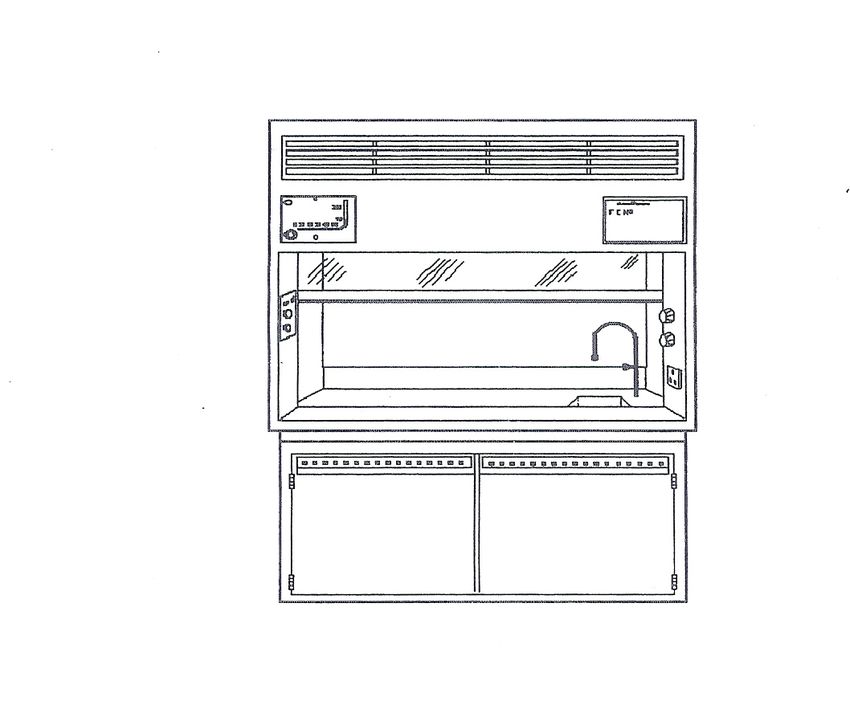
THIS DOCUMENT REPLACES THE NERC GUIDANCE NOTE – THE SAFE USE,
MAINTENANCE AND TESTING OF LABORATORY FUME CUPBOARDS, ISSUED IN 1994
                              AND UPDATED IN 2003 and 2005
This version refers to the new EN 14175 which replaces BS 7258 and further refers to NERC
containment values which are more stringent than those in the EN.

It is intended to support the NERC Procedure No19, COSHH and provides guidance on
legislation applicable to fume cupboards, specifications for fume cupboards and their safe
use.

Guidance is provided for:

                (a) planned preventative maintenance to meet the Statutory requirement for
                    thorough inspection under the COSHH Regulations and

                (b) the proof of satisfactory containment as required by NERC

                         (1) on fume cupboard enclosures following installation by the
                             contractor. Testing is the responsibility of the contractor and is
                             NOT covered by the manufacturers “type test”

                         (2) following major repairs or alterations to the fume cupboard or
                             room

                         (3) prior to the start of a high hazard process

                           COSHH assessments in NERC are based on containment as
                           recommended by HSE and the Royal Society of Chemists.
It should be noted that the standards set by NERC on the authority of the NERC Safety
Management Team are quantitative and therefore more stringent than the recommendations
in EN 14175
Satisfactory containment is established by the introduction of sulphur hexafluoride (SF6) and
monitoring the level of escape from the sash aperture. There will be situations where use of
sulphur hexafluoride is not possible (analytical work on fluorides, clean laboratories where the
equipment cannot be brought into the room etc.). Here we need a stepwise approach:
     • Look at the substances being used in the particular fume cupboard and put them
         through the COSHH software
     • If all of the substances require levels of containment below Class 2, no further action
         is needed since even a poorly performing cupboard will provide the general
         ventilation required for inhalation hazard Class B substances
If some substances require containment at Class 2 (inhalation hazard Class C substances),
monitoring concentrations in laboratory air replaces fume cupboard containment testing. Such
monitoring should be regular and documented. If the substances have WELs (Workplace
Exposure level) values (from HSE’s EH40 publication), these must not be exceeded
     • If some substances require containment at Class 1 (inhalation hazard Class D/E
         substances), monitoring in laboratory air should be accompanied by personnel
         monitoring to ensure that staff are not inhaling or otherwise absorbing the substance.
         Class 1 containment is normally required for substances which are carcinogens,
         sensitisers, genotoxins or cause long-term irreversible damage to health. We are
         obliged to ensure that exposure is kept to the minimum technically achievable.
         Records of personal exposure must be kept for 40 years. Seek advice for methods to
         biologically monitor personnel exposure which will be substance-specific If the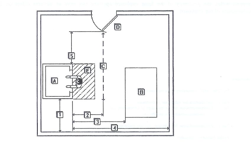
substances have WELs (Workplace Exposure level) values (from HSE’s EH40
publication), these must not be exceeded
List of contents

Part 1. Introduction.

     2.   Legislation.
          2:1. Health and Safety at Work etc Act 1974.
          2:2. Control of Substances Hazardous to Health Regulations 2002.
          2:3. Management of Health and Safety at Work Regulations 1999.
          2:4. Provision and Use of Work equipment Regulations 1998.
          2:5. Electricity at Work Regulations 1989.
          2:6. Environmental legislation.

     3.   Minimum specification for fume cupboard systems.
          3:1. System identification.
          3:2. System performance.
          3:3. Fume cupboard enclosure.
          3:4. Sash.
          3:5. Spill containment.
          3:6. Services.
          3:7. Air flow indicator.
          3:8. Ductwork.
          3:9. Fan.
          3:10. Fume discharge point.
          3:11. Positioning of fume cupboards.
          3:12. Make-up air.

     4    Safe use of fume cupboard systems.
          4:1. Risk assessment.
          4:2. Fume cupboard selection.
          4:3. Construction and configuration of experiment.
          4:4. Cupboard contents.
          4:5. Storage of materials in fume cupboards.
          4:6. Pre-use operator checks.

5.        Maintenance schedules.
          5:1. Frequency of maintenance.
          5:2. Hazards during maintenance work.
          5:3. Record keeping.
          5:4. Post maintenance performance testing.

6         Performance testing.
          6:1. Frequency of testing.
          6:2. Record keeping.
          6:3. Test principles.
          6:4. Instrumentation.
          6:5. Fume cupboard test procedures:
                   1). Containment.
                   2). Face velocity.
                   3). Flow visualisation.
                   4). Engineering measurements.

Appendixes:       A. Recirculating and portable fume cupboards.
                  B. Auxiliary air fume cupboards.
                  C. Wet-scrubbed systems.
                  D. Example documents.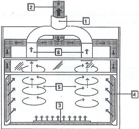
Part 1. Introduction
Fume cupboard systems are the most common control measure employed within NERC
laboratories for the prevention of exposure to hazardous substances. The legislation
governing their use, and the understanding of how they arrest and contain contaminants have
developed significantly over the last few years. It is intended that this Code of Practice will
establish a common operating policy throughout NERC in response to these developments.

The Code is intended for use by anyone with an interest in fume cupboard operations
including users, maintenance engineers and health and safety practitioners. The document
should be seen as a first reference source, but directs the reader to definitive source
documents where this might be useful. To enable easier identification of key
recommendations a series of section and sub-section numbering has been employed.

The Code is concerned mainly with permanently installed systems, although appendix A does
provide some guidance on recirculating portable devices. It does not consider microbiological
safety cabinets, or other forms of local exhaust ventilation (LEV).

Part 2. Legislation

The following is a brief summary of the main legislation relevant to the use of laboratory fume cupboards
in research environments. For further information the statutory instrument's, supporting Approved Codes
of Practice (ACOPs), and relevant NERC guidance notes should be referenced.

2:1. Health and Safety at Work etc Act 1974
The principle legislation regulating work activity by means of the establishment of various
general duties on employers to ensure, so far as is reasonably practicable, the health, safety
and welfare of employee's at work. This generality is expanded by the following subsections:

a) the provision and maintenance of plant and systems of work that are safe and without risks to health.
b) arrangements for ensuring the absence of risks to health in connection with the use, handling,
storage and transport of articles and substances.
c) the provision of information, instruction, training and supervision necessary to ensure the health and
safety of employees.
d)

Duties are established for employees to take reasonable care of their own health and safety, and that of
others, and to co-operate with their employees with regard to measures devised to ensure health and
safety ( ie. implement this code). In addition there is a section requiring employers to prevent harmful
emissions into the atmosphere.

2:2. Control of Substances Hazardous to Health (COSHH) Regulations 2002 These regulations are the
most significant in terms of the use of hazardous substances, and in the control measures used to
prevent exposure to them. The primary requirement is to prevent exposure of employees (or others
likely to be effected), but where this is not possible to make an assessment of the likely exposure, and to
thereafter control it to within acceptable level's (workplace exposure levels). Where necessary control
can be achieved by measures such as local exhaust ventilation (LEV), the classification of mechanical
ventilation devices in which laboratory fume cupboards are placed.

The regulations establish the requirement for LEV systems to be maintained in suitable condition, and
subject to thorough examination and testing at periods not greater than fourteen months, and more
frequently if the assessment identifies higher risk (Reg 9). This regulation is supported in some detail by
notes in the approved code of practice, which have been used as the basis for the maintenance section
of this code. There is a specific requirement for users of fume cupboards to make daily checks of certain
functions of the system, and to report any faults to management as soon as is reasonably possible.
2:3. Management of Health and Safety at Work (MHSW) Regulations 1999
The regulations require that a suitable and sufficient risk assessment be made prior to a work activity
being undertaken, and that the subsequent arrangements, along with the capabilities and training of
those required to do the work, are based upon this assessment. In terms of fume cupboard work this is
most relevant when considering the design of experiments within existing cupboards, and is fully
considered in part 4 of this code (Safe use of fume cupboard systems - 4:1. Risk assessment).

2:4. Provision and Use of Work Equipment (PUWE) Regulations 1998
These regulations are comprehensive in their requirements for work equipment, in which fume cupboard
systems are included. In general terms equipment has to be constructed and adapted so as to be
suitable for its intended purpose (Reg 5), maintained in efficient working order and in good repair (Reg
6). Maintenance operations are given further consideration (Reg 22) in order that sufficient protection is
afforded to maintenance workers, and to the prevention of the unintended discharge of any article, gas
or vapour (Reg 12). The unambiguous marking of controls, warning devices, and fault condition
monitors (ie flow indicators) is required and, in common with other legislation, the provision of adequate
information, instruction, and training is specified.

2:5. Electricity at Work Regulations 1989
This is relevant for the design and continued maintenance of the electrical systems associated with
fume cupboards. Particular attention should be paid to Reg 5 which establishes the need for the
mechanical integrity of electrical equipment, this being relevant to corrosion sometimes experienced by
electrical systems exposed to environmental
conditions. In addition the competence to undertake maintenance work (Regs 3 & 16), the need for
isolation of energy sources, and the use effective control measures (ie permits-to-work) (Regs 12 & 13)
are necessary precautions.

2:6. Enviromnental legislation.
This code does not detail measures necessary to meet environmental legislation such as the
Environmental Protection Act (EPA), or the Control of Pollution Act, as it is unlikely that laboratory scale
operations produce sufficient fume discharge to merit inclusion in these regulations. It is however
important to note that the following activities may require co-ordination with local enforcing authorities:

a) volume, concentration and composition of liquid waste discharge through the general drain system
(this being subject to a consent negotiated with the relevant water authority);

b) correct disposal of any special waste materials or contaminated apparatus through authorised
disposal sites in accordance with EPA.

Part 3. Minimum specification for fume cupboard
systems.

The following is a specification for the minimum requirements of a fume cupboard system for use within
NERC laboratories. Failure to meet this specification should result in either:

a) the complete withdrawal of the system from operation until modifications have been implemented to
eliminate deficiencies or

b) the limitation of use to low-risk work which has been subject to a risk assessment, and can be
undertaken safely within the system allowing for its deficiencies.

In order to achieve the standards set by NERC (which apply to fume cupboards in their installed
position), tenders should advise potential contractors of these requirements at the earliest
opportunity and should also make clear the requirements for the provision of a suitable make-up
air system.
3: 1. System identification.
All fume cupboard systems should be allocated a distinct identification number (eg. BGS-FC 1,CEH-FC
2), which should not be shared by any other system operating on that site. The number should be
clearly marked on all parts of the system, including ductwork and fans where these might be confused
with components of any other system.

3:2. System performance.
The primary function of a fume cupboard system is to contain and convey potentially dangerous or
obnoxious fumes from the fume cupboard enclosure to an outside discharge point where it can be safely
dispersed at low concentration. The operational system performance will be demonstrated in terms of a
containment test and face velocity measurements. Details of performance evaluation tests are given in
part 6 of this code.

3:3. Fume cupboard enclosure.
The enclosure shall be constructed of materials capable of resisting chemical or thermal attack from any
substance or equipment used within it, including during escapes other than during normal operations.
See EN 14175 for further details on material selection.

3:4. Sash.
The enclosure shall have a movable sash which will normally be lowered during operation, but which
can easily be positioned at a higher level to allow periodic access to equipment within.

3:4:1. The sash must be sufficiently transparent to encourage the user to work behind it. If the glass is
etched by acid, or marked by any form of obstruction it should be deemed unsuitable, and replacement
arranged. It may be necessary to protected it from acid frosting by means of additional resistant film on
the internal surfaces. In experiments where catastrophic failure can be explosive the sash should be of
laminated glass or other suitable impact resistant material. Note Wired Georgian Glass is known to
release fragments on explosive impact, and is not deemed suitable for such conditions.

3:4:2. The sash mechanism must incorporate a device to limit its movement such that a maximum
aperture height of 0.5 m is maintained between the base of the cupboard and the underside of the sash.
This is to be the considered as the maximum working aperture, and should not be exceeded during
normal operations. When it is necessary to exceed the maximum working aperture height, for instance
whilst loading equipment during the setting up experiments, it should only be possible to do so after
deliberately activating a stop-release mechanism.

3:5. Spill containment.
Where an experiment presents the possibility of accidental spillage of hazardous liquid within the
enclosure, it will be necessary to incorporate features to contain the spill within the enclosure. The
capacity of this feature must be capable of accepting the volume of the largest container housed within
the fume cupboard.

3:6. Services.
With the exception of electrical supplies, the outlets to services shall be located on the inner surface of
the enclosure. The controls shall be located on the external surfaces of the enclosure such that each
control can be unambiguously associated with its outlet, and visibly marked in accordance with relevant
standards.

3:6:1. Electrical outlets shall be located on the external surfaces of the enclosure, in such a position that
it shall not be possible for liquids or flammable vapours flowing over the cupboards front edge (from
spillages within) to come into contact with the electrical outlets.

3:7. Air flow indicator.
All fume cupboards should incorporate a means of unambiguously indicating to the operator that air is
being extracted at a satisfactory rate. Where audible alarms are fitted with a mute facility, it is not
permitted to carry out normal operation in the mute mode.

3:8. Ductwork.
Ductwork should be constructed of a material suitable for use with the materials intended for use within
the fume cupboard. See EN 14175 for comprehensive guidance on material selection.

3:8:1. It is strongly recommended that each fume cupboard shall have a dedicated duct system
and fan set. Where these are shared between more than one enclosure, facilities must exist to
indicate failure of any part of the system and communicate that failure to ALL other parts of the
system likely to be effected.

3:8:2. Where systems are used which allow the fumes from more than one enclosure to mix, a
comprehensive risk assessment must be made, and control measures introduced to prevent the
simultaneous use of incompatible substances.

3:8:3. Internal surfaces of ductwork should be smooth and free from obstruction.

3:8:4. The configuration of ducting should be designed to avoid features likely to allow the collection or
concentration of contaminant; for example any long horizontal duct runs should be slightly inclined, and
incorporate suitable drainage points.

3:8:5 All ducting should incorporate leak-proof inspection covers to allow easy internal inspections
during periodic maintenance and examination.

3:8:6. All ducting between the fume cupboard enclosure and the fan which passes through any occupied
space (ie offices or manned plantrooms) should be at negative pressure to the ambient room pressure
to prevent the leakage of contaminant into the room during plant failure.

3:8:7. No ductwork should violate the fire compartmentation of the building in passing between the fume
cupboard and its final discharge point. Duct runs should be external to the building wherever possible. If
this is not possible fire dampers will be required between compartments, and should be of suitable
corrosion resistant design, be readily accessible for inspection and maintenance, and be regularly
tested.

3:8:8. Where mechanically operated volume control dampers are located in a duct, they must
incorporate a feature to deter the unauthorised operation. A lock-nut and an appropriate warning sign
should be sufficient.

All parts of the fan likely to come into contact with the fume or its condensate should be resistant to
them, and be able to withstand the maximum working temperature.

3.9. Fan
3:9:1. The fan motor should be situated outside the air stream to prevent the transmission of sparks to
any potentially explosive fume within.

3:9:2. Designs incorporating indirect drive using pulley belts are recommended as they are known to
allow flexible operation over a range of speeds (therefore air flow rates).

3:9:3 All components of the fan must allow access for inspection and maintenance,
particularly the internal drum of the fan and its casing.

3:9:4. Belt drives must be adequately guarded to prevent accidental entanglement.

3:9:5. Fan sets and associated plant mounted externally at roof level should incorporate barriers and
other safety features to prevent falls during maintenance activities..

3:9:6. Fan assemblies should incorporate vibration damping gaiters between isolating ducting and

discharge stack. This will reduce noise transmission and reduce the potential for fatigue failure

throughout the duct system.
3:10. Fume discharge point.
The complex conditions influencing the effectiveness of a fume discharge point are described in various
literature and include building geometry, local meteorological and topographic conditions, and a host of
other variables. In the absence of numerical modelling or wind-tunnel analysis the following basic
guidance should be sufficient to maximise safety at discharge positions.

3:10:1. All exhaust stacks shall be of vertical circular section discharging at a height no less than 3m
from roof level. The stack should incorporate a conical accelerator to increase discharge velocity and
assist in fume dispersal.

3:10:2. The airflow velocity at the discharge point shall not be less than 10m/sec.

3:10:3. The fume should discharge above roof level (see 3:10:1), with care to avoid re-capture of any
expelled contaminant by either natural ventilation features (windows) or other plant air -intakes.

3:10:4. When considering the discharge characteristics it is worth considering the worst likely
environmental considerations, (ie a calm wind-less day). Flow visualisation using smoke generating
devices may be a valid test for such conditions.

3:10:5. Certain limitations can be enforced by Local Authority Planning Departments in accordance with
Town and Country Planning Regulations, typically restricting stack height. Where this compromises the
safe operation of a system it will be appropriate to seek further advice from the LA.

3:10:6. Where fume cupboard discharge points on roofs are likely to expose maintenance workers (or
others staff) requiring access to adjacent areas, it will be necessary to operate systems of work which
will prevent exposure to hazardous concentrations of effluent. A permits-to-work system may be valid
control measure.

3:11. Position of cupboard.
The position of a fume cupboard within a room will influence its ability to contain contaminants, so care
must be taken to avoid close proximity to features known to cause adverse effect. These include: a)
walls, columns, cabinets, work benches, or other features likely to disturb the flow of air through the
enclosure: and b) traffic routes through the laboratory likely to result in disturbance. These problems are
reduced by ensuring there is an undisturbed zone within which the operator can work at the enclosure
face.

Figure 1.

       Feature of critical dimension.                                                              Distance (mm)

    A Fume cupboard enclosure.                                                                           N/A
B Bench positioned behind enclosure. "
C Traffic route. "
D Door. "
E Undisturbed operator zone - Width of enclosure x 1000mm approx. "
1 Distance from side of enclosure to nearest wall or significant body (ie cabinets, 300
column etc) Note. This does not include a second fume cupboard enclosure.
2 Distance from face of enclosure to traffic route. 1300
3 Minimum distance between face of enclosure and work bench. 1500
4 Minimum distance from face of enclosure to rear wall or major feature. 2000
5 Spacing between undisturbed zone and any regularly opening door. Fire escapes 1000
not in normal use are excluded from this requirement.
See BS 7258 :Part 2: 1980 Section three for further details.
3:12. Make-up air.
Fume cupboard systems should be provided with facilities to replace the air extracted from the room by
the fume cupboard. This can be achieved by either positioning grilles in walls or doors to allow induction
of treated air from adjacent offices or corridors although this method is not preferred due to potential
disruption of airflow from adjacent events. Ideally, untreated air should be drawn from outside, and
conditioned by a dedicated air handling unit. Care must be taken when utilising such powered make-up
air, as the influence of high velocity currents within the proximity of the fume cupboard aperture can
have an adverse effect on the containment performance of the cupboard. The make up air should be
introduced at low velocity and as far as possible in line with, but not adjacent to the face of the
enclosure.
Part 4. Safe use of fume cupboards.
A fume cupboard is a partial containment device and therefore, if the contaminant is so hazardous that
any leakage into the working environment would be considered catastrophic, an alternative control
measure will be necessary, for example a glove-box or microbiological safety cabinet.
The success or otherwise of the control afforded by a system will be dependant upon its suitability for
the intended circumstances and must be determined by a series of pre-activity planning measures, the
most significant being the risk assessment.
4:1. Risk assessment.
Prior to any new experiment being undertaken within a fume cupboard it will be necessary to complete a
risk assessment exercise. This may be considered as part of a COSHH assessment, but will include
elements additional to chemical safety. The risk assessment will identify the hazards (ie substances or
conditions with the potential to cause harm), and evaluate the associated risks (ie the likelihood of that
harm being realised). The assessment must consider conditions other than the normal operating ones,
ie spillage, catastrophic failure of any component within the system (ie fan), or any other condition likely
to present adverse conditions. The assessment must consider the competence of those undertaking the
work, and will determine the necessary levels of supervision. In all but low risk situations, where the
reasoning of the assessment can be readily demonstrated, it will be necessary to produce a written
record of the assessment.
Where a number of risks are anticipated it is useful to employ a rating system to allow
comparison between risks, and enable appropriate priorities to be allocated. Site Local Safety
Advisers should be approached for additional information on numerical risk assessmentstechniques. 4:2. Fume cupboard selection. The hazards presented by an experiment must be matched to the capabilities of the system, therefore it is essential that performance data (ie containment test results) are considered as part of the risk assessment. In laboratories containing a number of fume cupboards it is likely that some will perform better than others. In such circumstances efforts must be made to use the most effective cupboards with the most hazardous experiments. The physical integrity of the system must be considered, ie its ability to withstand corrosive acid fumes or its fire resistance when using highly flammable substances. EN 14175 should be reference for comprehensive construction material data. It is important to consider all parts of the system (ie ducting, fan-casing etc), and not just the enclosure. 4:2:1. No work should be carried out in a cupboard which has not been subject to a thorough examination and performance test within the last twelve months. A label should be displayed on each cupboard indicating when the last test was carried out. 4:3. Construction and configuration of experiment. The configuration of the apparatus within the cupboard will have a critical influence on the airflow through the enclosure, and therefore its ability to contain the contaminant. The following points should be noted; 4:3:1. A 150mm wide equipment-free-zone should be maintained behind the sash at all times Experimental evidence has shown that if contaminants are released in this area there is a higher possibility of them being drawn out of the cupboard by convection currents caused by operator movements. 4:3:2. The use of large objects such as ovens inside an enclosure is known to have an adverse effect on performance and should be avoided if possible. If it is necessary to incorporate such equipment a full containment test should be arranged with the equipment in situ. It may be that alternative local exhaust ventilation devices are more appropriate for the contaminant release conditions presented by such equipment. 4:3:3. The apparatus within a cupboard must be configured to allow the operator the access necessary for normal attendance with the sash in as low a position as is possible. When using hotplates it may be necessary to use angled tongs for any manipulations if the combined height of the hotplate and beakers prevent the sash from being lowered to a level sufficient to provide splash protection. Suitable personal protective equipment must be warn, for example lab coats, gloves and face shields. 4:3:4. Under no circumstances should an experiment require an operator to position their head inside the cupboard enclosure at any time whilst hazardous substances are present. 4:3:5. The structural rigidity of any apparatus must be sufficient to withstand the likely stress present. Temporary configurations using adhesive tape and other short-term measures are not acceptable for even the shortest duration experiment. 4:3:6. Adequate guarding of hazards such as hot surfaces, moving machinery, or electrical conductors must be in place. Appropriate warning signs should be displayed. 4:4. Cupboard contents. There may be occasions when maintenance staff or other persons not directly involved with the experiments need to know what substances are being released into the system. A drywipe board or other readily modified medium should be displayed near the fume cupboard, on which the hazardous substances currently being used can be recorded. In addition a contact name and internal telephone number should be provided. An out-of-hours number may be required if the substances are sufficiently hazardous to present major difficulties during-any plant failure, or if the experiment is likely to be adversely effected by a power failure or other unplanned event outside normal working hours.
4:5. Storage of materials in fume cupboards.

The storage of supply containers and other items will have an adverse effect on the airflow through the
enclosure, and subsequently the containment performance of the system. The following rules must be
adhered to at all times;

4:5:1. Supply containers stored in a fume cupboard enclosure must be limited to those materials
currently being used in the experiment, and then must be limited to a maximum amount required for a
single days work. If the supply container exceed the daily requirement it will be necessary to store them
in an alternative location.

4:5:2. Materials other than those in current use should be stored in an alternative location, preferably in
a suitable ventilated cupboard incorporating features to contain the volume of the spillage of the largest
container held within.

4:5:3. Storage cupboards located below the enclosure can sometimes be ventilated by diverting some of
the extracted force via a small (ie less than 50mm diameter) flexible hose connecting the cupboard
space with a point on the ducting. Maximum benefit is achieved if the doors to the storage cupboard are
perforated to allow make-up air to pass easily through.

4:5:4. NO unnecessary equipment such as hotplates or equipment stands should remain in a fume
cupboard enclosure if they are not part of the experiment currently being conducted.

4:5:5. Light-weight items such as tissues, disposable gloves and filter-papers should be securely stored
within the fume cupboard to prevent them being sucked through the enclosure as they become
impacted around fan blades, causing subsequent loss of extract performance.

4:6. Pre-use operator checks.

Before the start of every day during which the fume cupboard is to be used, the operator ( or a
designated competent person from the laboratory) must complete a simple checklist to confirm the
following basic functions of the system;

1. Operation of the on/off controls.

2. Operation of the sash mechanism.

3. Note the reading of a performance indicator (ie manometer) if fitted.

4. Operation of internal light.

The check will present the opportunity to note any deficiencies in the system performance, which should
be recorded and brought to the attention of the supervisor as soon as possible. If subsequent daily
checks show that fault has yet to be repaired the supervisor should be reminded, any further delay in
repair should be brought to the attention of the site Safety Adviser

4:6:1. The record of this check must be signed and dated. An example record document is shown
below, and should be displayed within close proximity of the cupboard at all times. Completed record
sheets shall be achieved and be available for inspection by site Safety Advisers.
Fume cupboard Pre-use operators checklist. (Tick to confirm)
                                      To be completed on EACH day that the fume cupboard is used.

     Fume cupboard No                   Location.

   Date        On/off        Sash         Flow         Internal             Fault conditions               Signed.
                                        indicator        light

Part 5. Maintenance schedules.
A fume cupboard system will require regular examination and maintenance to ensure continued safe
operation (I). This maintenance must be extended ALL parts of the system, and should be in the form of
a programme of planned preventative maintenance.

5:1. Frequency of maintenance.
The primary legislative requirements are found in the Control of Substances Hazardous to
Health (COSHH) Regulations (see Part 2), which require control measures used to prevent
exposure to hazardous substances to be maintained in an efficient state, in efficient working
order and in good repair. In addition thorough examination and tests must be carried out at
least once every fourteen months. In practice this frequency of testing may be increased in
accordance with the risk assessment of the effects of system failure. The schedule
recommended in this code of practice includes elements at both six and twelve monthly
intervals. Where system failures would result in significantly high risk of exposure it may be
appropriate to halve the indicated intervals, or supplement them with additional measures.
These examinations are additional to the pre-use operator checks.

5:2. Hazards during maintenance work.
It must be recognised that maintenance activities will present those undertaking them with them hazards
other than those present during normal fume cupboard operations. It may be necessary to make
separate risk assessments of the maintenance work, and to devise adequate safe systems of work
which incorporate appropriate levels of competence, training, and supervision.

5:2:1. All work involving the interruption of normal fume cupboard operation's must be carried
under the control of a permit-to-work system. An example of a permit to work is shown as
appendix B.

5:2:2. Where maintenance work is carried out by contractors it is important to ensure that all relevant
safety information is communicated between all parties. This might include the findings or risk
assessments, details on substances used in the system, or any hazardous aspects of the maintenance
work which might effect the laboratory or anyone working within it.

5:3. Record keeping.
Written records of maintenance work must be kept, including details of all repaired and replaced
components. These records should be signed and dated by those responsible for the work.

5:4. Post maintenance performance testing.
It will be necessary to carry out testing following any maintenance work likely to influence the systems
performance. This will include face velocity, containment, or engineering component testing. See part 6
of this code for further details.
Interval between
                                                                                    maintenance.

   Fume cupboard maintenance schedule.
                                                                                             Twelve
                                                                              Six Months.
                                                                                             months.

Enclosure.
Visual examination to ensure integrity of enclosure, including seals around
main panels, sinks and other services. Check storage voids underneath              *
main
aperture.
Check operation of enclosure light.                                                *

Replace enclosure light (ie fluorescent tube).                                                  *

Controls.
Activate on/off switch to confirm operation, and note operation of
associated                                                                         *
warning lights.
Operate any other warning devices (ie sash height or low-flow switches) to
                                                                                   *
confirm operation.
Check air flow indicator device. In case of liquid manometer disconnect
tubing and re-zero, then switch on fume cupboard and note movement of              *
fluid column. Carry out face velocity checks
Sash.
Repeated movement of the sash through its entire travel to confirm ease of
                                                                                   *
operation (lubricate where necessary).

Operation of working aperture stop and over-ride mechanism.                        *

Check alignment of pulleys and condition of pulley wires, (replace any
                                                                                                *
distorted or broken wire).
Inspect sash screen for cracks, chemical attack, or any other damage
likely                                                                             *
to adversely effect transparency of the screen.
Interval between
Fume cupboard maintenance schedule continued…. maintenance.
Six Months. Twelve
months.
Ducting.
Examine fume cupboard-to-ductwork connection to confirm seal and physical
*
condition.
Visual examination of entire ductwork run for mechanical damage and leaks,
including internal sections where condensate or any other concentrations are *
likely to cause damage.
Mechanical volume flow control dampers should be inspected to confirm
*
freedom of movement, and absence of internal obstruction.
Fire dampers examined for corrosion, and operated where possible. *
Flow sensing devices, or any other equipment located within the ductwork
should be examined and replaced if damaged. *
Fan.
Check flexible coupling (including tie-clips) to ductwork for damage, wear,
*
or leakage.
Visual examination of anti-vibration mountings. *
Visual examination of all external features for mechanical integrity. *
Visual examination of inside the fan casing to confirm physical integrity, and
*
absence from obstructions (ie tissues, rubber-gloves, filter papers).
Examination of electrical supply cables, switch-gear, connectors and
*
isolators for physical damage and continued electrical operation.
Check rigidity of exhaust stack. *
Check condition and tension of drive belt, re-tighten or replace if necessary. *
Fit new drive belt. *
Check drive-shaft bearings for excess movement or other signs of wear. *
Re-grease bearings. *
Lubricate electrical motor in accordance with manufacturers
*
recommendations.
Part 6 : Fume cupboard performance testing.
Performance testing is necessary to confirm that the system and its individual engineering components
are operating to a level necessary to provide the desired fume arrest, containment, and dispersal. It is
appropriate in the following circumstances:
6:1. Frequency of testing.
COSHH regulation 9 established a duty on employers to carry out thorough examination and
test of engineering control measures at least once every fourteen months. In cases where therisks associated with a particular experiment are high it will be necessary to increase the
frequency of these examinations and tests. The decision on frequency can be determined by
risk assessment, which should anticipate the likely outcome of a system failure.
Containment testing should be carried out
a) as part of the commissioning of new installations,
b) following major repairs or alterations to the fume cupboard or room
c) prior to the start of a high hazard process
6:2 Record keeping.
The regulations require that suitable records are produced, and these records are maintained for at least
five years from the date of last test. The approved Code of Practice (ACOP) in support of COSHH
establishes the test requirements, and has been used as a basis for the schedules recommended in this
guidance. Example record documentation is given as appendix B.
6:3. Test principles.
In the past, fume cupboard performance has been monitored by measuring the rate at which air is
drawn across the open aperture, this being known as face velocity, and a nominal range of acceptable
values have been suggested by various sources usually between 0.5 - 1meter per second. Research
has shown that the mechanisms by which contaminants migrate across the aperture boundary are a
function of complex aerodynamic conditions, and are not necessarily related to face velocity, making its
measurements an unreliable indicator of performance. It is now generally accepted that a better
indicator is the ability to arrest and retain a gaseous challenge released within the enclosure, the
leakage being quantified by means of externally positioned detection devices, and referred to as
containment testing.
In addition to the above measurements it is necessary to monitor the performance of the prime movers
and other engineering components within the system, including the measurement of air velocity and
pressure in ducting, and the speed and direction of fan impellers.
6:4. Instrumentation.
The equipment necessary to carry out the tests detailed in this section are available for use at NERC
sites through the arrangements of the Safety Equipment Pool
6.5 Fume cupboard test procedures.
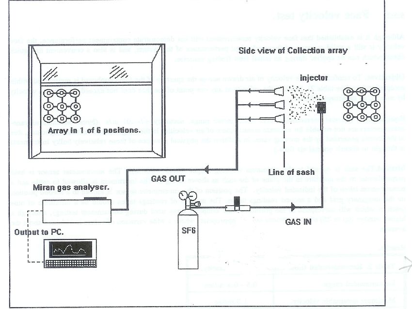
6:5:1. Containment test.
Equipment. Invent UK Ltd "Safecheck" test system- including Miran infra-red gas analyzer.
-
Objectives. To establish the containment performance of the system to enable direct comparison
between systems and, in cases where more than one system is available, to allow fume cupboards to
be more effectively matched with the hazards associated with specific hazardous substances and
experiments. The cupboard can be tested either empty or inclusive of normal operating apparatus, the
latter being more representative of operating conditions.
Method. A gaseous challenge of sulphur hexafluoride (SF6) in nitrogen is injected into the enclosure at
a precisely controlled rate to simulate the release of a contaminant within the cupboard. An array of
sampling heads is positioned at the enclosure aperture and allowed to collect any SF6 which is able to
migrate across the boundary. Leakage is detected by means of an infra-red gas analyzer, connected to
a PC which allows real-time display of the data as a trace of leakage (ppm) against time. The
measurement is repeated with the array in six positions across the aperture.
Results. Containment performance is expressed as leakage of SF6 in parts per million (ppm), both as a
mean and an instantaneous maximum value. The values awarded to each cupboard are those
corresponding to the worst of the six array positions. These values are then applied to the classification
categories listed in table 1, which includes guidance on the limitations of use for the system in the light
of its performance.Full details of this test can be found in Specifications handbook for fume cupboard performance tests:
Procedures, requirements and gradings. Invent UK Ref INV/92/12. See also EN141754.
Table1: Fume cupboard performance and classification:
Mean SF6 Max SF6 NERC Substance Notes
ppm ppm Class hazard class
(class A
substances do
not require a
fume cupboard)
0.40 4 Withdraw from use
Figure 2 Safecheck containment test system (Invent UK Ltd).
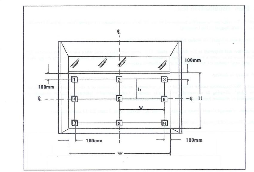
Factors to consider when assessing containment test results.a) If a number of fume cupboard systems are present within a single laboratory it is desirable to match the fume cupboard with the best containment performance with the processes using the most hazardous substances. b) The NERC COSHH Procedure No. 19 and the NERC COSHH database software recommend the class of fume cupboard needed based on the inhalation hazard classification for particular substances. c) If containment performance is poor, particularly in specific areas of the aperture (eg. corners), adjustments should be made to any variable factors likely to effect performance. For example increasing/decreasing air flows, repositioning internal baffles, or the re-configuration of apparatus within the cupboard. In addition it is known that the retro-fitting of aerofoil sections along side edges of the enclosure, and to the bottom edge of the sash will increase containment performance. 6:5:2. Face velocity test. Although it is established that face velocity measurement will not demonstrate containment performance, the face velocity is still a valid measure of the mechanical performance of the system, and is also a convenient and quick check which can be applied during an initial fault finding exercise. Objectives. To confirm that the velocity of air drawn across the aperture of the fume cupboard is maintained within accepted values (see table 2), and that the velocity at anyone point of the face does not exceed the average velocity by more than an accepted factor. Equipment. Thermal anemometer. 0.15 - 2.5 m/sec range, accuracy +/- .01 m/s (Note. Mechanical vane anemometers are not suitable for accurate measurement of air velocities in the ranges found in fume cupboards, due to the inertia generated by the moving vane. In addition the physical presence of these relatively bulky instruments is thought to disturb normal air flow.) Method .The sash is opened to the maximum working height (0.45 - 0.5 m). The anemometer sensor is held perpendicular to the aperture in the plane of the sash as shown in fig 2. The instrument is allowed to settle and a measurement taken of the indicated velocity. The position of the anemometer sensor is moved to a second position on the imaginary grid and a second readings taken. The number of readings taken should be a minimum of nine (each of which will correspond to the position of the sampling array used during containment testing), although a higher number (up to 25) of test positions may be appropriate where a 'wide variation of values is obtained about the average. Results. Table 2. Recommended fume cupboard face velocity. Recommended range. 0.5 - 0.8 m/sec Maximum acceptable velocity. 1.0 m/sec Minimum acceptable velocity. 0.4 m/sec Maximum deviation from mean +/ - 20% velocity value of any other measurement within the grid.
Face velocity measurement grid.
W= Sash width R= Sash Height set to 0.5m max. w= (W - 200)/2 h= (H - 200)/2
Figure 3

Factors to consider when assessing face velocity results.

a) The range of acceptable values is open to debate. However in general the following generally
accepted principles; i) Face velocity too fast. Velocities greater than 0.8 m/ s are likely to generate eddy
currents around persons standing in front of the cupboard, and these are then able to draw
contaminants out through the aperture, particularly during movement by the operator.
ii) Too slow. It is unlikely that velocities below 0.4 m/s associated with older enclosures are able to arrest
and contain contaminants within the enclosure, particularly where external air movements due to
movement of staff or opening/closing of doors and windows are likely to exceed the face velocity.
Modern enclosures may be designed to operate at lower velocities but effective containment must be
demonstrated by an SF6 challenge.

b) Where fume cupboards are found to have face velocities which lie outside the recommended or
acceptable values, steps must be taken to modify the system. Improvement measures include;
i) Decrease or increase of velocity. a) If a manually operated volume control damper (VCD) is fitted in
the ducting of a system this can be closed down to reduce the airflow, or opened up to increase it. The
fitting of VCDs is encouraged as they allow variable control within the system. b) Altering the ratio of
motor-to-fan drive pulleys by fitting different diameter pulleys is an option on indirect drive
configurations. On direct drive systems the motor speed has to be altered, either by electronic controller,
or replacement with an alternative motor.
ii) Increase only. Where air flow is inadequate, and pulley changing will not achieve greater performance
from the fan, it will be necessary to fit a fan and motor assembly capable of higher performance.

c) The effect on the performance of the system as a result of adjustments to the air flow rate should be
assessed by subsequent testing.

6:5.3. Engineering measurements.
a) Air velocity and volume flow rate in ducting.
i) direct velocity measurement using a thermal anemometer, or ii) taking velocity-pressure
measurements using a pitot static tube and pressure sensor inclined manometer, electronic manometer,
or magnahelic gauge and subsequently converting pressures into velocity by calculation. The sensor
has to be moved across the area of the duct in incremental steps.

Note. In circumstances where air temperature deviates significantly from 16°C (+/-2°) it will be
necessary to incorporate suitable correction factors when measurements are taken.

Conversion to volume flow rates.                                                                              .
Velocities in ducting can be converted to volume flow rates by multiplying the average velocity by the
cross sectional area of the duct.

Ave velocity (m/sec) x C.S.A (m2) = Volume flow rate (m3/sec)

It is often convenient to convert this value into m3/hour, achieved by multiplying m3/sec by
3600.

b) Fan
i) Volume flow rate. Use same method and equipment as for measurement of flow in ducting.

ii) Static pressure at inlet and outlet. A pressure sensing device (fluid manometer, magnehelic
gauge) is connected to a pre-existing port located on each side of the fan housing. Tubing is
used to connect the port to the appropriate side of the gauge (positive or negative) and a
reading is taken on each side. Typically the negative reading will be of greater magnitude
than the positive, and will be in the range of 100 - 300 Pa.

iii) Velocity at discharge point (efflux velocity).
This is measured by positioning a velocity sensor in the flow at the point that it leaves the
discharge stack. A mechanical displacement anemometer will be of sufficient sensitivity for
this measurement.

                     -
Preferred range =15 20 m/sec
Minimum =10 m/sec.

See BS848:Part 1:1980

c) Speed & direction of rotation of fan & motor.
Use of either a direct contact or optical tachometer will give an indication of the rotational speed of the
motor and fan shafts.

Visual inspection of markings on fan case to confirm correct direction of rotation. This is an important
point to check because a fan running in the wrong direction will still move air, but much less efficiently.
The direction of rotation can be unintentionally reversed by connecting the electrical supply wires
incorrectly, so post maintenance checking is recommended.

Appendix A:

Recirculating                    and           portable               duct-less                 fume
cupboards
This guidance covers the use of duct-less fume cupboard systems which draw air through an open
enclosure, and pass it through a replaceable molecular filter, allowing expulsion back into the laboratory
air for recirculation. The principle concerns regarding this type of equipment is that the filter elements have a finite absorbent capacity, which if exceeded can allow hazardous concentrations of contaminant to breakthrough the filter into the laboratory atmosphere. For this reason the use of such a system should only be considered where ducted systems are not reasonably practicable, for example in temporary field laboratories. Use must only be permitted if a suitable risk assessment has been carried out taking into account the following recommendations; a) the appropriate filter must be selected for the substances to be used. Consideration must be given to the compatibility of substances. b) calculations must be made to establish the release characteristics of the contaminant, these should be applied to determine the maximum time the system can be used before exhausting the filter element. The likely date of exhaustion must be clearly displayed on the system, and communicated to staff using the system. c) a system of work must be devised to monitor the use of the system, for example the actual release of contaminant and duration of use. A record of the system use shall be maintained and made available for inspection by all staff likely to use the system. d) the system of work must consider the handling and disposal of contaminated filter elements, which are likely to be classified as special waste, and require appropriate disposal. Appendix B: Auxiliary air fume cupboards. The fundamental design difference between these and standard fume cupboards is the use of air supplied into the enclosure at positive pressure to assist in the ventilation of contaminated air being extracted by a conventional negative pressure fan-set. The arrest of contaminant is achieved by a scrubbing motion caused by two contra-rotating vortexes. Whilst most of the procedures established by this code are valid for both standard and auxiliary air fume cupboards, the following points specific to the latter should be noted: a) Because the arresting mechanism is dependant upon the effective operation of two independent plant systems (extract and supply), it is important that maintenance, examination and testing is extended to all relevant equipment, particularly the air handling unit providing the supply air. b) The arresting motion is maintained by a curtain of supply air blown into the front of the enclosure via vents at the front and sides. This is unlikely to result in face velocities within the ranges traditionally considered as acceptable for standard fume cupboards, therefore face velocity can not be relied upon as a performance indicator. Air velocities and volume flow rates can be measured for both the supplied and extracted air, with system performance being confirmed by containment testing (See 6:5 of this code).
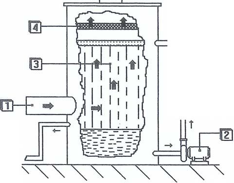
1) Extract air (OUT) 2) Supply air (IN) 3) Front supply vent 4) Side supply vent 5) Contra-
rotating vortexes 6) Extract ports in ceiling of enclosure.

Figure 4

Appendix C:

Wet scrubbed systems.
Fume cupboard systems used with high concentrations of corrosive substances (ie. perchloric and
hydrofluoric acids) require the dilution of the contaminated airstream prior to discharge to reduce the
environmental impact, and prevent damage to the system components. Dilution is achieved by directing
the airstream through an enclosure incorporating a water spray, and optionally filter media. This enables
the arrest (scrubbing) of the contaminant within the water stream, allowing the collection of waste within
a sump, and ultimate discharge in diluted concentration via a suitable drain.

Failure of plant providing the water wash would result in unacceptable release of concentrated fumes,
therefore it is necessary to make arrangements to ensure effective maintenance. In some cases it will
be valid to provide emergency back-up, for example by incorporating a second water pump. Planned
preventative maintenance and regular examination and testing of the scrubber system are
recommended.

The efficiency of the system can be determined by monitoring the concentrations of contaminant within
the airstream on both sides of the scrubbers by using Drager tubes or similar detectors. Concentrations
of contaminant within the liquid waste stream can be monitored using indicating papers. This will confirm
compliance with relevant Water Authority consents to discharge via the drains.
Figure 5

Key: 1. Airstream IN from fume cupboard enclosure: 2. Water circulation pump: 3. Shower: 4.
Spray eliminator:
5. Airstream OUT to fan.
Appendix D:

Example documents

1. Record of examination and test of laboratory fume
cupboard.

2. Fume cupboard pre-use operators checklist.
Record of examination and test of laboratory fume cupboard.
1.Equipment & Location. FC Number. Site:
Building:
Type: Room:
Manf: Date of last examination and test:
2.Process under control. Hazardous substances present.
1. 1.
2. 2.
3. 3.
4. 4.
3.Conditions at time of test
a) in service d) indicate contents at time of test.
b) stood down
c) other
4. Examination & test details Pass
Fail N/A Comments
a) Controls: i)Fan on/ off.
ii) Enclosure light
b) Flow indicators: i)Electro/mechanical
Light Audible warning
c) Enclosure: i)Sash operation
ii)Sash Height
warning.
iii)Sash Height limiter Light Audible warning
iv)Transparency of
sash
d) Face velocity measurements.
P1 P2 P3
Aperture width m Max sash Height m
Aperture area m² Sash Height during m P4 P5 P6
test
Mean velocity m/sec m³/Hr P7 P8 P9
Vol flow rate
Instrument used. Thermal anemometer Vane anemometer
Notes: 1. Recommended 0.45 to 0.5m sash Height.
e) Containment test. (Using safecheck SF6 gas challenge
Record file names:NERC
Classifcation SF6 Concentrations.
1 Mean SF6 Max SF6 P1 P2 P3
Mean Mean Mean
2 0.005-0.020 0.010-0.040
3 0.021-0.100 0.041-0.200 Max Max Max
4 0.101-0.200 0.201-0.400 P4 P5 P6
>0.201 >0.400 Mean Mean Mean
Max Max Max
1) See NERC “Safe use, maintenance and testing of laboratory fume cupboards (Part 6)” for
further details.
2) Use permit-to-work systems when interrupting normal FC operations.Record of examination and test of laboratory fume cupboard (cont).
f) Ducting measurements. Diameter m Temp in duct ºC
Velocity pressure Pa Transport Velocity m/sec
Volume flow rate m3/hr Measurements by Thermal anemometer Pitot-
tube
Visual inspection. Pass Fail Comments
i) Mechanical integrity.
ii) Condition of seals & vibration
dampers.
iii) Condition of volume control dampers.
iv) Operation of fire dampers.
g) Fan Type: Centrifugal. Serial Number:
In-line radial. Direction of rotation marked: CW ACW RPM
Bifurcated Motor details: RPM
Static pressure IN Pa (-) Static P OUT Pa (+) Efflux velocity m/sec
Visual Inspection. Pass Fail Comments.
i) Inside impeller clear of debris
ii) Impeller blades intact
iii) Drive belt.
iv) Mechanical parts (integrity &
corrosion)
v) Electrical system (as above)
5. Report, repairs and corrective maintenance requirements.
Fault Action Date completed
1. 1.
2. 2.
3. 3.
4. 4.
5. 5.
6. 6.
Further comments:6. Details of person carrying out examination and test.
Name: Designation:
Date of test: Signature:
Fume cupboard Pre-use operators checklist. (Tick to confirm)
To be completed on EACH day that the fume cupboard is used.
Fume cupboard No Location.
Date On/off Sash Flow Internal Fault conditions Signed.
indicator lightYou can also read