Lindab Industrial Doors Technical Information - Lindab Doorline TM

Page created by Emma Cooper
 
CONTINUE READING
Lindab Industrial Doors Technical Information - Lindab Doorline TM
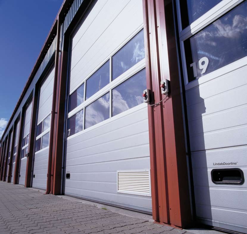
Lindab Doorline   |   Te c h n i c a l I n f o r m a t i o n I n d u s t r i a l D o o r s

Lindab Doorline TM

Lindab Industrial Doors
Technical Information
Lindab Doorline               |   Industrial Doors

A reliable, environmentally compatible system...

Fulfils the latest requirements for              are the constructional elements that nor-        Maintenance
applicability and safety in accor-               mally determine which rail system is             According to the new CE standard (EN
dance with EN 13241-1                            most appropriate, but requirements on            13241-1), maintaining doors on an on-
                                                 clearance etc. may be decisive in this           going basis is a requirement. But at least
Lindab Doorline is an all-round range of         connection (see page 4-7).                       one annual inspection must be carried
sectional overhead doors characterised                                                            out by an authorised fitter.
by convincing functionality, design, and         Delivery and installation                          In connection with a high rate of use
finish.                                          Lindab Doorline products are delivered           and/or a corrosive environment we rec-
    Great flexibility and many combination       and installed as agreed in connection            ommend more frequent attention to
options make it easy to »tailor-make« the        with each door system. After installation        these areas. Arrange a service agree-
door so that it fits perfectly into any build-   the fitter ensures correct tension of the        ment.
ing.                                             springs and balance of the door leaf, so
    Panorama sections should be chosen           that the door will function to the opti-         More information
where as much light as possible is re-           mum and is ready for use.                        You are always welcome to contact
quired. If insulation properties are deci-                                                        Lindab for more information, advice, and
sive insulated sections will meet this de-                                                        guidance.
mand – individually or com­bined, with
window types as required.
    Wicket doors can also be built into the
door leaf if needed.
                                                    Table of contents:                                                       Page:
    The wide range of different surfaces
and choice of colours also helps to pro-
                                                    Rail system:                                                                3-7
file Lindab Doorline sectional overhead             Main components · jamb installation · suspension · type list
doors as ideal architectural and con-
structional systems.                                Door leaf:                                                                8-11
    The environment and safety have also            Main components · materials · colours and surfaces
been given high priority. The ­choice of            Types and construction principles · windows and panels · weight
environmentally compatible materials                Sealing · heat insulation · safety
and tried and tested safety meas­ures
places Lindab Doorline at the fore­front of         Wicket doors:                                                                12
developments with regard to the envi-
                                                    Facade doors:                                                                13
ronment and safety.
    Lindab Doorline quite simply means
                                                    Facade options and range of colours:                                         14
high quality, individual systems, con­
sider­ation for the environment, and safe­          Attachment and door accessories:                                             15
ty on rails.
                                                    Electrical operation:                                                        17
Choice of rail system                               Space requirement
It is important as early as the planning
stage to consider the rail system, sus-             Choice of electrical operation:                                          18-19
pension, the side room, and clear­ance,             Level of safety · Type of operation · Level of training
etc., so that the door can be adapted to,
                                                    Control system:                                                          20-21
installed, and function in the building the
best possible way. Always try to install
                                                    Electrical operation – accessories:                                      22-28
the rail system as close to the ceiling as
possible. This will provide the most sta-           Lindab Doorline descriptions:                                            29-30
ble suspen­sion and the optimum utilisa-            Car wash – Sectional overhead doors
tion of room height.
Head room and the pitch of the ceiling

2
Lindab Doorline                   |     Industrial Doors

                                                                               12                                                         5

Rail system
                                                                                                                                                        11 6
                                                                                            11

                                                                                                                                     7

                                                                                                                  10                            9
                                                                                                       3                                   8
                                                                           4
                                                                                                                                 2
                                                                                                                         2

                                                                           When the torsion springs are in-
Main components                                                            stalled at the end of the rail sy-
                                                                           stem, two suspension fittings
Jamb                                                                       must also be mounted at the
1. Angled jamb (right and left side)              12                              end as shown here.
                                                                                                                                                                1
2. Profile for spring support (can be or-                                                                                    Jamb, rails, suspension
dered)                                                                                                                       fittings, etc., are made
                                                 Jamb – dimensions and                                                       of galvanised steel.
Rails
3. Horizontal rail (right and left side)         installation
4. Spring bumper                                                          A. Standard jamb
                                                                          dimensions and
5. Suspension fitting (see table on this                                  installation.
page for the necessary number of sus-                                     (The dimensions
                                                                          indicated are at floor
pension fittings).
                                                                     95

                                                                          level. Width and
Spring system                                                             depth are greater
                                                               72         higher up).
6.  Bearing plates (optionally with spring
break safety device).                                                 B. Light wall reinforced
                                                                      with an RHS jamb
7. Supporting plate (number depends on
                                                                      construction.
door specifications)                                                                                       Footing recessing for jamb
8. Spring shaft, diameter 25,4 mm
                                                                                                           Note: If the top edge of the footing is higher
9. Spring (torsion spring with a lifetime of                                                               than the finished floor a recess must be made
at least 22,000 openings and closings).                   min. 130    C. An RHS profile can                         a. Dybde
                                                                                                           in the footing for the=jamb.
                                                                                                                                    afstanden ind
                                                                      create the necessary                             til portramme / løsholt
10. Cable drum                                                                                             a. Depth ­distance to the door jamb / cross bar
                                                                      space at the side if this is
(Various types depending on rail system                               lacking.                                     b. Bredde min. 130 mm
                                                                                                           b. Width, min. 130 mm
and door size)                                                        See page 6 in connection
11. C-profile (not with L-rail system)                                with Low headroom.
(Used as a distance measurement to en-
sure that all rails are constantly parallel).   Floor construction around the door
12. On low lift rail systems the spring                                                                                                        a
should be placed at the end of the hori-
zontal rails. The bearing plates should be
installed on horizontal RHS profiles
which are attached to the horizontal
                                                                                                                                                           b
rails.

Installation – vertical jamb
A. The angled jamb is supplied with the                                                                 Suspension fitting
vertical rails and an effective, integrated                                                             Length of horizontal             Min. number of
side sealing. The jamb is normally                                                                      rails:                           suspension fittings:
                                                C. In situations where there is insufficient
screwed directly to the wall with only a                                                                0-2900 mm                        1 per rail
                                                side room for the door jamb, this can
single tight-fitting joint in between. In                                                               2901-4900 mm                     2 per rail
                                                normally be solved by installing a suit-
connection with particularly irregular
                                                able RHS profile in the door aperture as                4901-5900 mm                     3 per rail
walls there should also be an extra jamb
                                                a base for the jamb.                                    5901 mm -                        4 per rail
joint between the wall and the jamb pro-
                                                Note that this will reduce the effective
file. See table on Attachment, page 15.
                                                door width by the dimensions of the                    Installation ­horizontal rails
B. In connection with light and/or weak
                                                RHS profile (min. 2 × 130 mm).                         Horizontal rails are supplied with an inte-
wall constructions it may be necessary
to use a reinforced jamb construction                                                                  grated C-profile as reinforcement. The C-
such as RHS profiles. This jamb con-                                                                   profile is used to install bearing plates,
struction is an extra measure that can be                                                              spring bumpers and suspension fittings
supplied and installed by agreement.                                                                   which, with adjustable retaining plates,
                                                                                                       are easy to install and adjust.

                                                                                                                                                                3
Lindab Doorline                    |     Industrial Doors

Standard
Rail system: S and ST
                                                                                                                                                                                              S                                   ST

                                                                                                                                                                  Construction details
                                                                                                                                                                  H: Height of aperture
                                                                                                                                                                  B: Width of aperture
                                                                                                                                                                  Ov/Oh: Height above door, left and right
                                                                                                                                                                  Sv / Sh: Side room, left and right
                                                                                                                                                                  D: Depth
                                                                                                                                                                  T: Ceiling pitch
                                                                                                                                                                  A: Stable area for affixing screws
                                                                                                                                                                  G: Floor configuration adjacent to door
                                                                                                                                                                  – see p. 3
                                                                                                                                                                  Height above door, side room, and
                                                                                                                                                                  depth must be regulated to the near-
                                                                                                                                                                  est obstacle.
                                                                                                                                                                    Support frame

Side room (Sv and Sh)        Head room (Ov and Oh)                          Depth (D)                                   Clearance (F)                                               An extra support frame in

                                                                                                                                                                                                                                     H+O
                                                                                                                                                                                    connection with a light wall
                                                                                                                                                                                    must have a hight of:

                                                                                                                                                                                    Aperture + head room
               S                        O                                         D                                                      F
             SSS                        O
                                        OO                                       D
                                                                                 DD                                                    FFF                                          Also see "Jamb - dimensions
                                                                                                                                                                                    and installation" page 3.
    Horizontal section                 Vertical section                       Vertical section

    S standard                                              S                                                                                                 ST
                                                                                                                                                                                                     D
    ST standard with roof pitch                                                                                                                                                                                                            325
                                                                                                     D

                                                                                                                                             325
                                                             O                                                                                                  O
                                                                                  785                                                                                                785
                                                O
                                                                            350                                                          F                                                   Roof pitch max. 35º
                                                             H                                                                                                  H

                         Normally used where
                         head room
                         O = 430 - 1000 mm

                                                                   Sv                                                                    Sh                          Sv                                                                    Sh

                                                           The grey field around the rail system indicates the operating area of the door / necessary free space. The accompanying dimensions indicate the dimensions of the field in millimetres.

Installation dimensions                                                                    S Standard                                                                       ST Standard with roof pitch
Height of aperture, H mm                                       0-3860                         3361-5570                          5571-7850                            0-3860                      3861-5570                      5571-7850
Head room, min. O mm                                             430*                                450                                530                                -                               -                              -
Head room, min. O mm with roof pitch < 25°                           -                                   -                                -                             430*                             450                           530
Head room, min. O mm with roof pitch > 25°                           -                                   -                                -                              480                             500                           550
Depth, min. D mm                                              H + 700                            H + 700                            H + 700                          H + 700                        H + 700                         H + 700
Clearance, F mm (+ possible increased free                H + 105 (+ FF)                   H + 105 (+ FF)                     H + 105 (+ FF)                               -                               -                              -
clearance, FF)
Side room, Sv and Sh, min. mm                                130** /***                         130** /***                         130** /***                       130** /***                     130** /***                      130** /***
* Min. 450 mm with electrical operation. ** Minimum 200 mm for motors with chain pull on the side where the motor will be located (remember addition).
*** Min. 350 mm for standard motor location on the side where the motor is located.
FF: Increased free clearance. Height above door minus minimum height above door (see table) = the extra height that the free clearance can be increased by –
but 200 mm at maximum.

4
Lindab Doorline                                            |      Industrial Doors

High lift
Rail system: H and HT
                                                                                                                                                                                           H                                    HT

                                                                                                                                                              Construction details
                                                                                                                                                              H: Height of aperture
                                                                                                                                                              B: Width of aperture
                                                                                                                                                              Ov/Oh: Height above door, left and right
                                                                                                                                                              Sv / Sh: Side room, left and right
                                                                                                                                                              SvK / ShK: Side room, left and right,
                                                                                                                                                              with console
                                                                                                                                                              D: Depth. T: Ceiling pitch
                                                                                                                                                              A: Stable area for affixing screws
                                                                                                                                                              G: Floor configuration adjacent to door
                                                                                                                                                              – see p. 3
                                                                                                                                                              Height above door, side room, and
                                                                                                                                                              depth must be regulated to the nea-
                                                                                                                                                              rest obstacle.

                                                                                                                                                                 Support frame

Side room (Sv and Sh)       Head room (Ov and Oh)                       Depth (D)                                   Clearance (F)                                               An extra support frame in

                                                                                                                                                                                                                                 H+O
                                                                                                                                                                                connection with a light wall
                                                                                                                                                                                must have a hight of:

                                                                                                                                                                                Aperture + head room
             S                       O                                        D                                                      F
           SSS                       O
                                     OO                                      D
                                                                             DD                                                    FFF                                          Also see "Jamb - dimensions
                                                                                                                                                                                and installation" page 3.
  Horizontal section                Vertical section                      Vertical section

 H     high lift                                        H                                                                                                 HT
                                                                                                                                                                                                 D                                      325
 HT high lift with roof pitch

                                                                                                                                                                                 785
                                                                                                                                                             O
                                               O
                                                                                                                                                                                         Roof pitch max. 35º
                                                                                                                                                                                 Normalt 1000 mm

                                                                                                                                                             H
                       Normally used where
                       head room
                       O > 1000 mm

                                                                                                                                                                 Sv                                                                    Sh

                                                       The grey field around the rail system indicates the operating area of the door / necessary free space. The accompanying dimensions indicate the dimensions of the field in millimetres.

Installation dimensions                                     Installation dimensions                                                                  Hight of aperture ≤ 5050                                       Hight of aper­ture
– without console                                           – with console                                                                                                                                          > 5050
Head room, min., O mm              1000                     Head room, min., O mm                                                                    1850*-2519                     2520-3345                       3346-4425
Depth, min., D mm                  H + 910 ÷ HL             Depth, min., D1 mm                                                                      H + 910 ÷ HL                    H + 910 ÷ HL                   H + 910 ÷ HL
Clearance, F mm                    H + O ÷ 440              Depth, min., D2 mm                                                                      505                             505                            505
High lift, HL mm                   F ÷ H + 105              Clearance, F mm                                                                         H + O ÷ 440                     H + O ÷ 440                    H + O ÷ 440
Side room, Sv and Sh, min.         130-170** /***           High lift, HL mm                                                                        F ÷ H + 105                     F ÷ H + 105                    F ÷ H + 105
mm                                                          Side room, SvK and ShK, min. mm                                                         230                             230                            300
The minimum side room de-
pends on the height of the                                  Side room, SvK and ShK, min. mm, with                                                   350                             350                            420
door (H) and high lift (HL).                                ­electrical operation
The smaller HL, the greater                                 Note:                                                                                   Roof pitch                      Roof pitch                     Roof pitch
Sv/Sh.                                                                                                                                              not possible                    max. 35º                       max. 35º
* Minimum height with a console. ** Minimum 200 mm for motors with chain pull on the side where the motor will be located (remember addition).
*** Minimum 350 mm side room for standard motor location on the side where the motor will be installed.

                                                                                                                                                                                                                                                 5
Lindab Doorline                    |     Industrial Doors

Low lift
Rail system: L and LT
                                                                                                                                                                                              L                                     LT

                                                                                                                                                                 Construction details
                                                                                                                                                                 H: Height of aperture
                                                                                                                                                                 B: Width of aperture
                                                                                                                                                                 Ov/Oh: Height above door, left and right
                                                                                                                                                                 Sv / Sh: Side room, left and right
                                                                                                                                                                 D: Depth
                                                                                                                                                                 T: Ceiling pitch
                                                                                                                                                                 A: Stable area for affixing screws
                                                                                                                                                                 G: Floor configuration adjacent to door
                                                                                                                                                                 – see p. 3
                                                                                                                                                                 Height above door, side room, and
                                                                                                                                                                 depth must be regulated to the nea-
                                                                                                                                                                 rest obstacle.
                                                                                                                                                                     Support frame

Side room (Sv and Sh)        Head room (Ov and Oh)                         Depth (D)                                   Clearance (F)

               S                        O                                        D                                                      F
             SSS                        O
                                        OO                                      D
                                                                                DD                                                    FFF

    Horizontal section                 Vertical section                      Vertical section

    L    Low lift                                          L                                                                                                 LT
                                                                                                                                                                                                     D                                          50
    LT Low lift with roof pitch                                                                                                                                                                                                            220-2
                                                                                                    D

                                                            O                                                                                                    O
                                                                                                                                            220
                                                                                                                                             til
                                                                                                                                            250
                                                                                                                                                                                      590-666
                                                 O                                590-666
                                                            H                                                                           F                        H                                         Roof pitch max. 28º

                         Normally used where
                         head room
                         O = 220 - 430 mm                                                              B                                                                                                  B

                                                                  Sv                                                                    Sh                           Sv                                                                    Sh

                                                          The grey field around the rail system indicates the operating area of the door / necessary free space. The accompanying dimensions indicate the dimensions of the field in millimetres.

Installation dimensions
Width of aperture, B mm                                            0-6100
Head room, min. O mm                                               220*
Depth, min. D mm                                                   H + 1000
Clearance, F mm                                                    =H
Clearance, F mm with built-in wicket door                          F = H ÷ 50 / H ÷ 100
Side room, Sv and Sh, min. mm                                      130** /***
Max. door weight, kg                                               300 (ca. 25 m²)
Standard roof pitch degrees                                        5º / 10º / 15º / 20º / 28º
* Minimum 250 mm for electrical operation. ** Minimum 350 mm side room on the side where the motor will be installed.
*** Minimum 150 mm side room at suspension iron – and at cable tensions (if electrically operated).

6
Lindab Doorline         |     Industrial Doors

                                                                                                                          V

Vertical
Rail system: V

                                                                                                              Construction details
                                                                                                              H: Height of aperture
      500           A                          A       500                   A          500
                                                                                                              B: Width of aperture
                   Sv    Ov                                            Oh    Sh                               Ov/Oh: Height above door, left and right
                                                                                              D
                                                                                                              Sv / Sh: Side room, left and right
      500                                                                               500
                                                                                                              D: Depth
                                                                                                              T: Ceiling pitch
                                                                                                              A: Stable area for affixing screws
                  SvK                                                        ShK                              G: Floor configuration adjacent to door
                                                                                                              – see p. 3
                                                                                                              Height above door, side room, and
                    A                                                        A
                                                                                                              depth must be regulated to the nea-
                                                                                                              rest obstacle.
                                                                   H

                                                             B                                                 Support frame

              Min. 100                                                 Min. 100     G

Side room (Sv and Sh)         Head room (Ov and Oh)              Depth (D)                Clearance (F)

              S                      O                              D                                F
            SSS                      O
                                     OO                            D
                                                                   DD                              FFF

  Horizontal section                Vertical section             Vertical section

 V vertical

                                              O

                    Normally used where
                    head room
                    O = ≥ H + 400 mm

Installation dimensions
Height of aperture, H mm                                                                            0-3300          3300-5950        5951-7200
Head room, min. O mm                                                                                H + 400         H + 400          Ask Lindab
Depth, min. D1 mm                                                                                   475             520
Depth, min. D2 mm                                                                                   505             505              530
Side room, Sv and Sh, min. mm                                                                       130             130              130
Side room, Sv and Sh, min. mm, door with electrical operation (motor side)                          350             350              350
Side room, SvK and ShK, min. mm, door with console.                                                 210             230              300
Side room, SvK and ShK, min. mm, door with console and electrical operation                         350             350              420
(motor side).

                                                                                                                                                    7
Lindab Doorline             |   Industrial Doors

Door leaf

Main components
 1. Door section (LDI or LDP – see
    page 9)
 2. Window (several types ­– see page
    10)
 3. Window or filling (see page 9)
 4. Built-in wicket door (see page 12)
 5. Handle (internal/ external)
 6. Roller
 7. Barrel bolt (standard locking de-             Door leaf seen from inside
    vice)
 8. Bottom fitting (optionally with spring
    break safety device)                         LDI - vertical section                    LDP - vertical section
 9. Side hinge
10. Top fitting
11. Middle hinge
12. Wind reinforcement
13. Ventilation grid (various sizes)
14. Rubber seals along all edges (see
    page 11)

Materials
LDI ­insulated sections
LDI sections have a core of extruded
polystyrene ­ a strong, high insulation
and environmentally compatible mate-
rial which also effectively prevents bur-
sting due to frost, as the water absor-
bency of polystyrene is only 0.5%.
   The polystyrene core is laminated with
aluminium-stucco (a hard type of alumi-
nium sheet with a slight relief effect) or a
                                                                               A                                        A
steel-stucco sheet which has been given
a surface treatment of 25 my polyester
                                               A. Bottom rubber seal in connection with electrical operation: See page 21.
lacquer (the surface treatment fulfils the
requirements of corrosion class 3).            Colours and surfaces                      special lacquers as required. Top and
   The model with steel-stucco panels          LDI sections of aluminium-stucco are      bottom cassettes, panels, door cas-
is always recommended where there              available untreated, treated with one     settes, ventilation grids, etc., can be
is a need for a stronger surface to re-        of the many prelacquered standard         supplied lacquered as required at an
sist knocks and bumps.                         colours, or specially lacquered.          extra charge.
                                                 One of the many standard colours          A colour chart showing the many
LDP ­panorama sections                         or special lacquers can be chosen as      polyester and aluminium pre-lacque-
The jamb profiles of the LDP sections          required for LDI sections with poly-      red colours can be ordered.
are made of extruded and anodised              ester lacquer.
aluminium, which have great strength             LDP panorama sections are often         Note: There may be differences in sha-
and a high degree of finish. Windows           supplied anodised in the natural co-      des between wet and powder lacque-
and panels – see page 10.                      lour, but it is also possible to choose   red surfaces.

8
Lindab Doorline       |   Industrial Doors

Construction door leaf

                                                                                       LDI
Door leaf types and construction principle                                             Door leaf type LDI is constructed in 46
The door leaf is constructed in horizontal sections with a length that                 mm insulated sections and a height of
corresponds to the door aperture + side overlap.                                       600 mm.
                                                                                          The optimum insulation can be
                                                                                       achieved with the fewest possible sec-
                                                                                       tions (door joints). The ideal door
                                                                                       height for the LDI type are therefore as
                                                                                       shown in the table below.
   LDI                                                                                  Optimum door height - LDI
                                                                                            Number of          Door aperture
                                                                                             sections           height, mm
                                                                                                4                    2450
                                                                                                5                    3050
                                                                                                6                    3650
                                                                                                7                    4250
   LDP                                                                                          8                    4850
                                                                                                9                    5450
                                                                                                10                   6050
                                                                                                11                   6655
                                                                                                12                   7250

                                                                                       The different types of window for buil-
   LDC (LDI + LDP)
                                                                 980                   ding into LDI sections are shown on
Door section LDI                                                                       page 10.
window TT20
                                                                                       LDP
                                 600
                                 434

Window dimensions are from
the outside of the frame                                                               Door leaf type LDP is constructed in
                                                          792                 TT20     panorama sections. The sections can
                                                                980                    be manufactured in individual heights­
Door section LDI
                                                                                       see drawing to the right.
window TT10
                                 330

                                                                                         The flexible section heights make it
                                 600

Window dimensions are from
the outside of the frame                                                               possible to manufacture a door leaf
                                                        635                   TT10
                                                                                       with sections of the same height, irre-
                                                                980
Door section LDI
                                                                                       spective of the height of the door
window PCD                                                                             aperture.
                                       192
                                 600

Window dimensions are from                                                               The vertical field divisions of the pa-
the outside of the frame
                                                         624                  PCD      norama sections are also variable ­see
                                                                       88              drawing to the right.
Door sections LDP                                                                        Panorama frames are equipped with
a.          Top section                      88
b. Intermediate section          a     b                                               the window types and fillings that are
                                                                48
c. Bottom section                                                                      shown on page 10.
including bottom rubber seal
(A section height of 600 mm is                         133                             LDC
recommended)                     c                                                     LDI and LDP sections can be freely
                                                                                       combined to create door leaf type LDC.
30 mm overlap at top
25 mm overlap on each side                   88 1) / 168 2)      500 - 1400             Max. aperture width
                                                                                               LDI                  8000 mm
1) With aperture width < 4100    2) With aperture width > 4100
                                                                                               LDP                  6000 mm
Both dimensions are excl. the bottom rubber seal.
                                                                                               LDC                  7500 mm

                                                                                                                               9
Lindab Doorline                 |   Industrial Doors

Windows and fillings

LDI                                              Windows types                                                              LDI                                LDC/LDP
If windows are required in insulated
sections they will as standard be in-            Type:                                                  TT20               TT10               PCD               LDP section

stalled around the central axis of the           Shape:
section and with one window per
whole metre. Windows are installed
                                                 Light dimension, mm:                                708 × 350           551 × 246         570 × 135                 Variable
from the middle of the section and                                                                                                                                  se page 8
                                                 Light access, m²:                                      0,25                0,14              0,08
symmetrically to each side.
   Window types TT10, TT20, and                  U-value, total window section, W/m²K                   2,62                2,13              1,85             see type of pane

PCD are made with a solid plastic                Construction:                                      Plastic frame,     Plastic frame,     Plastic frame,       Extruded alu-
                                                                                                      screwed            screwed            screwed            minium profile
frame which is screwed together.
                                                                        SAN (two sides)
                                                                        28 mm ACRYL                                                                                 
LDP                                                                     Thermo                     U-value for window type SAN alone: 2,8 W/m²K
Panorama sections can be made with
                                                                        HD (two sides)
the required sizes of windows and fil-                                  28 mm HARD                                                                                   
                                                                        Scratch and chemical
lings within the limits stated on page 9.                               resistant                  U-value for window type HD alone: 2,8 W/m²K
Panorama sections will be made as
                                                                        WA (two sides)                                                                               
standard with the number of windows                                     28 mm WATER
                                                                        Car wash facilities        U-value for window type WA alone: 2,8 W/m²K
or fillings as shown in the table below.
                                                                        GP (single side)                                                                             
 Number of horizontal fields - LDP                                      28 mm PEARL
  Door aperture width       Min. and standard                           Granulated surface         U-value for window type GP alone: 2,8 W/m²K

        0-1400                      1
                                                                        GR (two sides)                                                                               
                                                                        28 mm Grey
      1401-2800                     2                                   Grey                       U-value for window type GR alone: 2,8 W/m²K
      2801-4000                     3                                   PC (single side)                                                                            
                                                                        28 mm POLYCARONAT
      4001-5400                     4                                                              U-value for window type PC alone: 2,8 W/m²K
                                                                        Burglary-proof
      5401-6000                     5
                                                                        DE3                                                                                           
                                                                        3 mm with single acrylic
Windows and/or fillings are installed in                                                           U-value for window type DE3 alone: 5,2 W/m²K
LDP sections with the help of elastic                                   DE4H                                                                                          
                                                                        4 mm hardened glass
butyl cord.                                                                                        U-value for window type DE4H alone: 6,0 W/m²K
                                                                        Filling
                                                                        28 mm polystyrene                                                                             
Note: If wicket doors are required in
                                                                        with aluminium or steel-
the door leaf, they will have an influ-                                 stucco surface             U-value for filling alone: 1,3 W/m²K
ence on the number and location of                                      STP1
windows ­- see page 12.                                                 Perforated steel sheet
                                                                                                                                                                      
                                                                        Hole size: 9,5 mm
                                                                        Air access: 50,8 %
 LDI door leaf
 Approximate weight per m²                                              STP2
                                                                        Perforated steel sheet
 LDI with aluminium-stucco              9,0 kg                          Hole size: 5,30 mm                                                                            
 LDI with steel/polyester           14,0 kg                             Air access: 40,0 %

 Calculating an estimated U-value for doors

 LDI 4 × 4 metre door without windows: U = 1,4 W/m²K.

 LDI with windows: U = 1,4 × sections without windows + UTT × sections with windows + Udoor                                                                Udør :
 		                          total number of sections        total number of sections
                                                                                                                                                           U     5
 LDP with windows and panels: U = 0,8 + Urude × sections with windows + Ufyldning × sections with fillings + Udoor                                               B×H
 		                                             total number of sections           total number of sections

 LDC with windows: U = 1,4 ×        LDI sections      + (Upane + 0,8) × sections with windows + Udoor
 		                          total number of sections                   total number of sections

10
Lindab Doorline               |   Industrial Doors

Tightness, heat insulation and safety                                                                                                                   cc
                                                                                                                                                             redited

                                                                                                                                                    A

                                                                                                                                                                       to
                                                                                                                                                  EN13241-1

                                                                                                                              Tightness
 Top seal                                                                                                                     Flexible, tightly-fitting rubber seals in
 A large, elastic rubber lip is installed on                                                                                  door joints and impact ensure optimum
 the top of the door leaf where it pres-                                                                                      sealing against the wind and thereby
 ses against the wall as an effective                                                                                         effective protection against irritating
 seal.                                                                                                                        draughts. The rubber seals are made
                                                                                                                              of 100% EDPM rubber, which main-
                                                                                                                              tains its elasticity in the entire tempera-
 Intermediate seal                                                                                                            ture range from +80º to ÷55° Celsius.

 The special design of the door joint to-
 gether with the built-in and securely
                                                                                                                              Heat insulation
 anchored rubber seal fully seals the                                                                                         The LDI sections have an insulation
 joints between sections.                                                                                                     property that is almost twice as good
                                                                                                                              as that provided by a similar thickness
                                                                                                                              of mineral wool.
 Bottom seal                                                                                                                     The table below shows the U values
                                                                                                                              for LDI sections and door leaves wit-
 At floor level the door is equipped with                                                                                     hout windows.
 a robust, flexible rubber seal.
                                                                                                                                 Naturally enough the number of
 The rubber seal is designed to effec-
 tively prevent draughts along the floor.                                                                                     windows has an influence on the over-
                                                                                                                              all insulation property of the door leaf.
                                                                                                                              Where panorama doors are concer-
                                                                                                                              ned it is primarily the type of window
 Side seal
                                                                                                                              and/or filling that determines the heat
 The side seal is installed on the door                                                                                       insulation provided by the door.
 jamb and is designed so that the rub-
 ber seal presses tightly against the
                                                                                                                              Safety
 door leaf when the door is closed.
                                                                                                                              All Lindab Doorline doors are CE label-
                                                                                                                              led and fulfil the requirements laid
                                                                                                                              down in EN 12453 and EN 13241-1
                                                                                                                              for electrically operated doors.
Lindab Doorline - applicability in relation to current standards
                                                                                                                                 The patented panel joints (Finger
Standard              Designation                 Standard class   Test result   Remarks                                      protection) effectively prevent fingers
EN 12424 / 12444      Wind load                   0-4              Class 3*      Normal use: must be min class 3 (25 m/s)     from becoming stuck in the door
EN 12425 / 12489      Water penetration           0-3              Class 3       Normal use: must be min class 2              joints. And further protection is provi-
EN 12426 / 12427      Air penetration             0-5              Class 3       Normal use: must be min class 2 - 4          ded against fingers becoming stuck in
EN 12428              Insulating property         Defined value    1,4 W/m² K    LDI, 4,0 × 4,0 m. door without wicket door   the door rollers by the safety discs that
                                                                                 and windows                                  these are equipped with.
*) A higher wind class can be obtained, please contact Lindab.                                                                   Accessories are also available for
                                                                                                                              Lindab Doorline in the form of a spring
 Finger protection door leaf and door roller                                                                                  break safety device** and a cable break
                                                                                                                              safety device so that it is also possible
                                                                                                                              to incorporate extra safety measures
                                                                                                                              into the door in these areas.

                                                                                                                              **) A spring break safety device is a demand in
                                                                                                                              the new CE standard for manually operated do-
                                                                                                                              ors and electrically operated doors that can be
                                                                                                                              released for manual operation.

                                                                                                                                                                         11
Lindab Doorline          |   Industrial Doors

Wicket doors

  Wicket door types                       Wicket door data
                                          Door type       Wicket       Min. / Max.        Min.              Remarks
                                                          door type    door aperture      door aperture
                                                                       width, mm          height, mm
                                          LDI                D31         1600-5000             2150         Door height < 2300 mm

                                                             D35         1600-5000             2300         Standard (recommended)*

                                                             D40         1600-5000             2565         Alternative

                                          LDP                D40         2200-5000             2000         Standard**
       D31
                                                             D30         2200-5000             2000         Alternative with high sections

                                          LDC                D31         2200-5000             2150         Not possible with windows in 4th section

                                                             D35         2200-5000             2565         Not possible with windows in 4th section

                                                             D40         2200-5000             2565         Standard**

                                          * With a door width > 3500 mm, door height must be at least 2500 mm.
                                          ** With a door width < 3500 mm, door height must be at least one section higher than the door.
                                          In order to achieve the optimum installation, panorama sections in the built-in door must be
                                          700 mm high at maximum.
                                          The free passage width of wicket doors is 910 mm (excluding protruding door handle, 65 mm).
                                          The wicket door has a bottom step at a height of 170 mm.
       D35
                                          The doors can be supplied with hinges on the right hand or left hand side, and always open
                                          outwards.
                                          Doors will be supplied as standard with a lock box, cylinder (drop-shaped), handle, and door closer.
                                          Doors can be supplied with other equipment by arrangement.

                                          LDI doors - wicket door location and windows per section

                                          Door aperture                                       Field                                    Max. number of
                                          width, mm                                                                                      windows
                                                                   1             2              3             4              5          per section

       D40                                1600-1959                                                                                           1

                                          1960-2939                                                                                           2

                                          2940-3919                                                                                           3

                                          3920-4899                                                                                           4

                                          4900-5000                                                                                           5

                                          With one window per section, this will always be installed in the wicket door. When several windows are
       D30                                required, these will always be installed symmetrically in relation to the centreline of the door.

Wicket door location in door leaf         LDP and LDC doors - wicket door location and windows per section
As the drawing to the right indicates     Door aperture                                       Field                                    Max. number of
the location options for wicket doors     width, mm                                                                                      windows
depend on the width of the door aper-                              1             2              3             4              5          per section
ture and thereby the number of fields     2200-3750                                                                                           3
that the door leaf can be divided into.
Also see page 9 for maximum and mi-       3751-4500                                                                                           4
nimum dimensions of LDP section
                                          4501-5000                                                                                           5
divi­sions.

12
Lindab Doorline       |    Industrial Doors

Facade doors

                                                                                          Facade doors are supplied ready for in-
Facade doors - types
                                                                                          stallation with jamb, lock box, cylinder,
                                                                                          handle, and door closer tailor made to
               1. (LDI)                 2. (LDC)                 3. (LDP)                 the dimensions of the door aperture.
                                                                                            Please note that door width must
                                                                                          not exceed:              Door height
                                                                                                                      1,9
                                                                                          LDI ­insulated sections
                                                                                          LDI sections have an extruded poly-
                                                                                          styrene core laminated with aluminium
                                                                                          or steel-stucco sheets.
                                                                                          LDP ­panorama sections
                                                                                           LDI facade doors
                                                                                           Min. aperture width with window type
                                                                                           TT20 = 1080 mm
                                                                                           TT10 = 955 mm
           1. Door constructed from LDI sections. Window types ­see page 10.
                                                                                           PCD = 905 mm

           2. Door constructed from LDI and LDP sections. Normally equipped with
                                                                                          Door sections constructed with extru-
           double-glazing (thermo). The doors are also available with two LDI sections.
                                                                                          ded and anodised aluminium profiles.
           3. Door constructed from LDP sections. Also available with all window and      LDC
           fillings types that are suitable for LDP sections.                             A choice of a combination of insulated
                                                                                          sections and panorama sections.

                                                                                          Vertical section
Facade doors: bottom and side details
                                                                                          The three different bottom fittings shown
                                                                                          can be chosen for facade doors. In ad-
Vertical                                                                                  dition, we recommend that facade do-
sections                                                                                  ors always open outwards and that a
                                                                                          slope is established on the floor as is the
                                                                                          case with the overhead doors.
                                                                                          B21
                                                                                          Standard bottom fitting with 50 × 30
                                                                                          mm anodised aluminium profile as a
                 B21                       B22                       B23                  door impact.
                                                                                          B22
                                                                                          Bottom door impact with 25 mm
                                                                                          brush seal.
                                                          Horizontal section A            B23
                                                                                          Bottom door impact with 25 mm
                                                                                          brush seal and floor profile in anodised
                                                                                          aluminium.
                                                                                          Horizontal section
                                                          Horizontal section B            Facade doors are installed in the door
                                                                                          aperture in prefabricated holes in the
                                                                                          jamb (see Horizontal section A) or in-
                                                                                          stalled with angles (see Horizontal
                                                                                          section B).

                                                                                                                                  13
Lindab Doorline               |      Industrial Doors

Facade options and colour program

It is always best to separate pedestri-       windows as those used in the door         Side panel and overhead panels are
an and vehicular traffic. It can therefo-     leaf.                                     well-functioning architectural options
re always be recommended to install                                                     in new buildings, but can also be used
entrance doors next to the door leaf,         Door apertures can similarly be equip-    in connection with renovation as it is
in a fixed side panel, for example.           ped with a fixed overhead panel made      possible to make a big door aperture
    Lindab can supply facade doors            of Lindab Doorline door elements. Si-     smaller, for example.
and side panels that match the door           milarly to the side panels, the over-
leaf with regard to shape, materials,         head panels can also come to create       Lindab Doorline door elements are
and colours.                                  a unified appearance in keeping with      also ideal for internal room divisions,
    Facade doors and side panels              the appearance of the door leaf.          such as in store-room divisions, fore-
can also be equipped with the same                                                      men’s offices, etc.

  Facade options                                                             d                                   c

  a. Door leaf
  b. Facade door
  c. Overhead panel facade door
  d. Overhead panel
  e. Side panel, optionally
     with wicket door

  Fields are supplied assembled or
  unassembled in consideration of
  transport.

                                                         e                   a                                   b

  Range af colours for doors - standard colours

  Colour                                                   Aluminium                             Steel - Polyester
                                                  LP-no.              RAL-no.*               LP-no.             RAL-no.*
  White                                           P9010                9010                   P010                9010
  Brick red                                          -                   -                    P742                8004
  Green                                           P6003                6003                   P874                6003
  Red                                             P3000                3000                   P412                3000
  Blue                                            P5010                5010                   P561                5019
  Brown                                           P8017                8017                   P434                8017
  Grey/white                                      P9002                9002                   P022                7044
  Yellow                                          P1023                1023                   P980                1021
  Steelmetallic                                      -                   -                    P045                9006
  Stone grey                                         -                   -                    P461                7038
  Slate grey                                         -                   -                    P087                7011
  Graphite grey                                      -                   -                    P036                7024
  Primed                                                           For further treatment by the customer
 *) Approximate

14
Lindab Doorline                          |     Industrial Doors

Attachment and accessories

 Attachment                                         Concrete                        Brick                           Hollow brick                  Lightweight                Steel                              Wood
                                                                                    (solid)                         (cellular brick)              concrete                                                      (full screw length)

                         Demand on underlying       Min. BN 25                      Compression strength            Compression strength          Compression strength       Min. steel 37                      Unclassified wood
Underlying

                         surface                                                    11 N/mm²                        20 N/mm²                      3 N/mm²                                                       Thickness: 45 mm
 surface

                                                                                                                                                                                                                Water content: 18-20%
                                                                                    Density                         Density                       Density                    Min. thickness
                                                                                    1720-1800 kg/m³                 1330-1380 kg/m³               535 kg/m³                  2 mm                               Tighten screws
  No. of screws per m.

                         Door width < 3 m                        2                               2                               6*                           3*                           2                                2

                         Door width 3-5 m                        2                               3                              10*                           4*                           2                                3

                         Door width 5-7 m                        3                               4                              14*                           6*                           3                                4

                         Door width 7-8 m                        3                               4                              15*                           7*                           4                                5

*) Lindab recommend installing an RHS jamb construction to attach the rail system of the door to.

            Various door accessories

            Spring break safety device                                                    Cable break safety device                                                Barrel bolt (internal)
            Type: FBS1                                                                    Type: WBS1                                                               Type: S

            Stops the movement of the door leaf immediately if the spring breaks.         Locks the door leaf immediately if the cable breaks.                     Supplied as standard for internal locking.

                                                                                                                                                                   Ventilation grid
                                                                                                                                                                   Type: Different varieties – ask Lindab.
            Outside lock                                                                  Safety lock
            Type: U2 (incl. cylinder)                                                     Type: S1                                                                 Type D11 is used in LDI section and in fillings. Available in two
                                                                                                                                                                   standard sizes, w x h: 600 × 157 mm and 600 × 297 mm. If a grid
            Lockable barrel bolt.                                                         Extremely robust barrel bolt with                                        is required in a complete LDP door filling, an E grid adapted to
            (Only for LDI sections).                                                      Ruko lock. (Only for LDI sections).                                      each individual door is used.

                                                                                                                                                                   Cable tension
            Spring cover                                                                  Hand chain with gear                                                     Type: RT1
            Type: FI1                                                                     Type: HT2                                                                A cable tension prevents the cable from leaving the
                                                                                                                                                                   wheel in connection with hand chain or electrical
            PVC tube to protect the spring, used in car washes, for example.              Steel chain and wheel for mounting on the spring shaft on the            operation. A cable tension can always be added.
                                                                                          right or left side.                                                      See page 18.

                                                                                                                                                                                                                                       15
Lindab Doorline   |   Industrial Doors

16
Lindab Doorline           |   Industrial Doors

                                                                                                                         redited
                                                                                                                    cc

                                                                                                                A

                                                                                                                                   to
Lindab Doorline electrical operation                                                                      EN13241-1

                                           Motor - possible locations
All Lindab Doorline industrial doors
can be fitted with electric control.
Electric control increases the con-
venience of the doors and reduces
operating costs.

Electric control consists of a motor
and a control system with control pa-
nel. The control system has a supply
                                           Motor with chain                           Motor with release device
cable with a CEE plug.

When required, basic electric control
can be expanded to include accesso-
ries such as an external push-button
box, remote control (allowing the door
to be operated at great distances), or
one of our other devices ­ see pages
22–24.

Space requirements
A. There must be at least 350 mm to
the side of the door at the point where
the motor is to be installed.              A. Space requirement for motor             Control system / control panel

B. The side room can be reduced to         A. Minimum 350 mm side room for stan-
                                           dard motor location.
200 mm by installing the motor in the
rail curve and using a chain pull. Plea-
se contact Lindab for information on
limitations on door weight and choice
of motor.

  B. Space requirement for motor

  B. Minimum 200 mm side room for motor
  installed in rail curve.

                                                                                      Motor - dimensions

                                                                 One metre of
                                                                 cable to the             106               175

                                                                 control system /
                                                                 operating panel.
                                                                                    218

                                                                                                                                        53
                                                                                                47,5
                                                                                                60

                                                                                          100          47,5
                                                                                                       60
                                                                                                          120
                                                                                                                     A 70 - 440

                                                                                                                                        17
Lindab Doorline               |   Industrial Doors

Choice of Lindab Doorline electrical operation

Before choosing electric control               Type of operation                          Choice of controls
It is important that the electric control      The text on the right and the table on     There is a description of the various ty-
system for your door matches your              the next page gives you an overview        pes of control and applicability options
needs and desires ­ while still meeting        of the various types of operation you      below.
the relevant safety requirements.              can choose between. Furthermore              Also see the table on the opposite
    You must find out in which sur-            you can see the connection between         page, which makes it easy to gain an
roundings the door will be installed (is       the level of safety and the type of ope-   insight into the different requirements
there public access?) and who will be          ration.                                    and choices in relation to the place the
authorised to operate it                                                                  door is located.
    (trained or untrained people?)             Level of training
    An example of public access is do-         The people who will be operating the       EHLDB without photocells
ors in car washes. Examples of places          door must have a level of training that    The door will operate automatically
to which there is not normally public          is in accordance with the door’s de-       when the control button is pressed.
access are agricultural and industrial         gree of automation.                        The door need not be visible from the
buildings, etc. Talk to your distributor if       It is a precondition that the people    place where it is operated.
you are in doubt regarding the require-        who will be operating the door in buil-    Use: Places where only trained per-
ments your door must meet.                     dings or areas with no or limited public   sonnel can operate the door.
                                               access, for example, have received         There is no requirement for photocells
Safety level                                   training in its use. There must be hig-    in this connection.
The level of security must be high in          her safety precautions in connection
surroundings to which there is public          with buildings or areas where there is     EHLDB with photocells
access and in principle anybody could          a risk that unauthorised persons could     The door can be operated automati-
press the operating buttons. The level         attempt to operate the door (at car        cally ­with the help of the push button
of security can be slightly lower in pla-      washes, for example).                      control, the hand transmitter, and
ces to which there is not public ac-              The table on the next page shows        other accessories ­ and the door can
cess and the people who operate the            the requirements in connection with        be operated even though it is not visi-
door have received training.                   the place the door is located, the type    ble when in operation.
                                               of building involved, and the type of      Use: Everywhere. Consideration need
                                               operation.                                 not be given to door location or to tra-
                                                                                          ining personnel to operate the door.
 Cable tension set
                                                                                          EHD – Dead-man electrical control
 Rail system, type        Number of               Prerequisites
                          cable tension sets                                              The door will only operate as long as
 S                        1
                                                                                          the push button on the control is held
                                                                                          down. Security lies in the fact that the
 ST                       1                       Roof pitch 10°
                                                                                          people who operate the door have re-
 L                        1                       Weight of door 125 kg                   ceived training.
                                                                                          External users can operate the door if
 LT                       1                       Weight of door 125 kg
                                                  Roof pitch 10°                          the »dead man control« is equipped
                                                                                          with a key switch that must be turned
 L                        2                       Weight of door > 125 kg
                                                                                          before the door can be operated. The
 LT                       2                       Weight of door > 125 kg                 users that will be operating the door
                                                  Roof pitch 10°                          must have received training before
 H                        1                       Head room 955 mm
                                                                                          they are given a key.
                                                                                          Use: Places with no or limited public
 HT                       1                       Head room 955 mm
                                                                                          access, e.g. agricultural buildings and
                                                  Roof pitch 10°
                                                                                          industrial buildings.

18
Lindab Doorline                  |    Industrial Doors

Choice of Lindab Doorline electrical operation

Choice of controls in accordance with EN 13241-1 / EN 12453

 Location                                            No or limited public access                           Public access
                                                      (few users)                                           (many users)

 Examples of types of                                - Agricultural buildings                              - Car washes building
 building                                             - Industrial buildings                                - Car repair shops
                                                      - Private property                                    - Supermarkets
                                                      - etc.                                                - etc.

 Users:                                              Owners and employees have access to operate           Everybody has access to operate the door and
                                                      the door (users are known).                           training is unnecessary.

 Type of operation:                                   Requirements:                                         Requirements:

 EHLDB without photocells                             Training required                                     Not possible

                                                                                                                                      ÷
 EHLDB with photocells                                Free access                                           Free access

 EHD - Dead-man electrical control*                   Training required*                                    Not possible

                                                                                                                                      ÷
*) External users can operate the door in places with limited public access if the door is equipped with a key switch and they have a key to this.

               The door must be visible during operation. Safe operation depends on the person operating the door.
       15-25 kg
               The door is operated by a push-button box. Will only open or close while the button is held down.

               The door is operated by a key switch. The key must be turned before the door can open or close.

               The door can be operated by a push-button box. Opens or closes automatically once the button is pressed.

               The door can be operated with a hand transmitter or other equipment.
               Operates automatically on a signal from the hand transmitter or other equipment.

      15-25 kg Indicates   the movement of the door during operation ­up or down.
       15-25 kg
          15-25 The
                kg    door will reverse direction if it meets an obstacle. The maximum pressure on the obstacle is 15-25 kg before reversing takes place.
           15-25 kg
               The door will stop and move upwards as soon as the light beam between the photocells is broken.

       15-25 kg
       15-25 kg
                                                                                                                                                            19
Lindab Doorline            |   Industrial Doors

Lindab Doorline electric control system

EHLDB-control
                                              EHLDB control
The control system has operating but-
tons and an error display function with                                                                  Frequency changer FO

light diodes.
                                              Supply voltage           3 × 230 V           3 × 400 V           1 × 230 V
•    Controls that fulfil EN 12453 regar-
                                              Frequency                 50 Hz               50 Hz                50 Hz
     ding safety and power monitoring
     (control of the »UP« movement).          Protection class           IP 65               IP 65               IP 65

     Tests carried out in accordance          Control voltage           12 VDC             12 VDC               12 VDC
     with EN 12453 regarding pressure
                                              Fuses                     3 × 10A            3 × 10A              1 × 10A
     on the bottom edge strip.
•    Monitoring of safety edge (DW            Connection            CEE 230V 3P+PE     CEE 400V 3P+PE      CEE 230V 1P+N+PE

     switch). Check carried out each
     time the door is closed.
•    Monitoring of photocells (foreign       •   DIP switch for selection of: auto-    •   Terminals for connecting external
     light ­short-circuiting of receiver).       matic closure, closure after per-         operating buttons or photocells.
•    Automatic recording of operating            sons have passed through, closu-      •   »Soft-touch« controls on control
     time.                                       re after vehicles have passed             unit and approved emergency
•    Electronic recording of closure             through, selection of pulsed/conti-       stop.
     time.                                       nuous post-run function.              •   Error signals on control unit for
•    Electronic recording of 1/2 open            This is an optional extra ­see page       easy fault tracing.
     position. This is an optional extra         24.                                   •   Read out off fault codes.
     ­- see page 24.                         •   Plug for communication to lighting    •   Read out off the number of times
•     Facility for mounting photocells in-       control and for connecting a ra-          opened.
      side the door jamb.                        dio.                                  •   Indicator for service intervals.

Motor system ­for EHLDB                      Motor t­ ype BF with release clutch       • Soft start/stop (FO2) is recommen-
• Mechanical end stop                        Motor with release clutch for emer-       ded in connection with large gates as
• 2 safety end stops                         gency opening in connection with a        this increases the lifetime of the gate.
• 2 available end stops for connec-          power failure.                            Also see page 28.
  tion to socket                                A spring break safety device is al-
• Control cable can be fitted with           ways necessary. For use with doors        Control system EHD ­with K motor
  plug                                       weighing more than 400 kg or where it     Dead man. Motor with built-in control
• 3 × 400 V/ 3 × 230 V selected by           is necessary to use the door as an        where the door can only be operated
  changing to a different socket.            escape route.                             if the push button on the control is
                                                                                       held down when opening or closing it.
Motor ­type BK with chain                    Motor - type FO with frequency            The motor is equipped with a chain for
Standard motor with chain for emer-          changer                                   emergency opening in connection
gency opening in connection with a           Motor with frequency changer which        with a power failure. The only acces-
power failure.                               provides the following options:           sories are a push switch or a key
  A spring break safety device is only                                                 switch.
necessary in special situations depen-       • Speed regulation and soft start/stop
ding on the weight of the door and           (FO1). Opening speed up to 500 mm
type of drum. On electrically operated       per second depending on drum. (Clo-
doors LP ensures this.                       sing speed up to 300 mm per se-
                                             cond).

20
Lindab Doorline                    |     Industrial Doors

Lindab Doorline electric control system

 Motor specification
                   Motortype              BK1                            BF1                              BF2                    BF3                        EHD
 Data
 Voltage                       3 × 230 V      3 × 400 V      3 × 230 V     3 × 400 V            3 × 230 V   3 × 400 V          3 × 230 V      3 × 230 V       3 × 400 V

 Frequency                      50 Hz            50 Hz        50 Hz             50 Hz            50 Hz           50 Hz         Variable            50 Hz           50 Hz

 Motor power                   0,52 kW          0,52 kW      0,37 kW           0,37 kW          0,52 kW         0,52 kW        0,52 kW            0,52 kW         0,52 kW

 Current                         3,8 A           2,2 A         2,9 A            1,7 A             3,8 A          2,2 A           3,2 A             3,3 A           1,9 A

 Protection class, motor         IP 54           IP 54         IP 54            IP 54             IP 54          IP 54           IP 54             IP 54           IP 54

 S3 running time               40 % ED          40 % ED      40 % ED           40 % ED          40 % ED         40 % ED        40 % ED         15 % ED        15 % ED

 Low bottom rubber seal (50 mm)

                                                                                          Types of motor
 Description
                                     BK1                       BF1                        BF2                      BF3**                               EHD

 Maximum door weight            330 kg ~ 30 m²            330 kg ~ 30 m²          500 kg ~ 45 m²            330 kg ~ 30 m²                   400 kg ~ 30–40 m²

 S/ST/L/LT rail system
 Max. aperture height***                 -                    5570                          -                         -                       -                    -

 H/HT rail system
 Max. height above door*             2305                     1780                        2665                        -                       -                   1500

 V rail system
 Max. aperture height                3170                     2670                        4040                        -                       -                   3300

 RPM                                     25                    29                          20                    27 v. 50Hz                  22                    30

 Closing and opening speed                                                                                  Max. 0,26 m/s v.
 (m/sec.)                                                                                                       330 kg
                                  0,14–0,27                 0,14–0,27                   0,14–0,27                                        0,14–0,27           0,18–0,39
                                                                                                            Max. 0,22 m/s v.
                                                                                                                500 kg

 High bottom rubber seal (100 mm) for use with H, HT, and V rail system

                                                                                          Types of motor
 Description
                                     BK1                       BF1                        BF2                      BF3**                               EHD

 Maximum door weight            330 kg ~ 30 m²            500 kg ~ 45 m²          500 kg ~ 45 m²            500 kg ~ 45 m²                   400 kg ~ 30–40 m²

 H/HT rail system
 Max. height above door ***              -                    4440                          -                         -                       -                   1500

 V rail system
 Max. aperture height                6640                     5600                          -                         -                       -                   3300

 RPM                                     25                    29                          20                    27 v. 50 Hz                 22                    30

 Closing and opening speed
 (m/sec.)                         0,18–0,39                 0,18–0,39                   0,18–0,39               Max 0,34 m/s             0,14–0,27           0,18–0,39

 Spring break safety device,
 compulsory                              No                    Yes                         Yes                      Yes                                No

 Cable break safety device        Additional                Additional                  Additional               Additional               Additional         Additional

* Maximum height above door cannot always be complied, due to size of drum.
** Opening speed up to twice closing speed, but not more than 0.5 m/sec.
*** Note that high bottom rubber seals cannot be installed on S and L rail system.

                                                                                                                                                                           21
Lindab Doorline          |   Industrial Doors

Technical Facts

Electrical operation – accessories
Push-button box, 3 buttons (rub3)
Extra control buttons UP-STOP-DOWN.

Type: BT1
70 × 135 × 50 mm.
Can be mounted as extra internal button or external push button.

Emergency stop, separate
Extra emergency stop.

Type: BT2
70 × 70 × 50 mm.
An emergency stop should be located at all operating points.

Push-button box, pulse type
Control button with pulse function.

Type: BT3
70 × 70 × 50 mm
Can be mounted as external button.
Standard FLIP-FLOP function, but can be used for UP, STOP or DOWN.

Key switch
Key operation with pulse function in key.

Type: BN3
75 × 90 mm.
Operated with single button operation in key. TILT is standard, but can also be
used for UP or DOWN. The cylinder can be replaced with a RUKO cylinder that
can be coded. Supplied with two keys.

Key switch
Key switch ON - OFF.

Type: BN4
75 × 75 mm.
Separate key switch for stop circuit or disconnection of the push button.
Is delivered with 2 keys.

22
Lindab Doorline   |   Industrial Doors

Technical Facts

Electrical operation – accessories
Key switch
Key switch UP-DOWN in key.

Type: BN1
70 × 130 × 70 mm.
Control button with UP-DOWN in key and separate stop.
Cylinder can be changed to encodable RUKO cylinder.
Supplied with two keys.

Key switch
Key switch ON/OFF in key.

Type: BN2
70 × 190 × 70 mm.
Control buttons opened by key. Cylinder can be replaced with encodable RUKO
cylinder. Supplied with two keys. The key must be inserted before the push-
buttons will work.

Code entry keyboard for door.

Type: BK1
70 × 70 × 15 mm.
UP is standard, but can also be used for FLIP-FLOP or DOWN.
Programmed with 4-digit code.
Requirement: Must be connected to 1 x 230 V.

Pull switch
Pull switch for cord operation.

Type: TK1
Control for ceiling mounting and activated by pulling a cord. FLIP-FLOP is
­standard but can also be used for UP.
 Requirement: Photocell, type FS1.

Bracket for pull-switch
Mounting bracket for pull switch.

Type: TG1
2000 × 500 mm. Used for mounting pull switch on wall.
Requirement: Pull switch, type TK1.

                                                                                                      23
Lindab Doorline           |   Industrial Doors

Technical Facts

Electrical operation – accessories
Photocell
Photocell protection of door aperture.

Type: FS1
Photocell protection must be used in accordance with the table on page 3.
(EHLDB control system cannot function with automatic closure or RM1 radio re-
ceiver unless photocells are fitted).

Automatic closing functions
Functions for automatic closure of doors are set by DIP switch. (Included as stan-
dard in EHLDB control systems). Type: AL1. Door closes after preset time. Type:
AL2. Door closes after preset time after vehicles have passed through photo­cells.
(Breaking time 1 second). Type: AL3. Door closes after preset time after persons
have passed through photocells. (Breaking time 0.05 seconds). Type A: When
Type A is added to AL2 and AL3, the door will close 10 minutes + preset time after
opening if photocells are not passed. Requirement: Photocells, type FS1.

1/2-1 open function
Encoding of 1/2-1 function.
(Included as standard in EHLDB control systems).
Type: EO2
Encoding of control system. Encode the control system for open in normal ope-
ration. Door can be fully opened by a long press on UP. Encoding is performed
directly on the control system.

Aerial, 433 MHz
433 MHz external aerial for receiver and fork-lift truck transmitter.

Type AM1, for aerial for receiver RM1.
Type AS1, for aerial for fork-lift truck transmitter TS99 200 mm.
Small aerial whip with fittings and 5 metres of cable. Can be connected to RM1
and TS99.

External selector switch,
automatic closing
Switch for automatic closure system.

Type: EO1
Switches automatic closing on and off.

24
Lindab Doorline   |   Industrial Doors

Technical Facts

Electrical operation – accessories
Radar
Radar operation of door.
Type: RA1
140 × 140 × 90 mm.
Directional radar able to distinguish between pedestrians and vehicles, cross
traffic, approaching or departing traffic. UP is standard, but can also be used for
FLIP-FLOP or DOWN. Requirements: Photocells, type FS1. Requires separate
12-24 V supply and socket (UD1 can be used).

Road detector
Inductive detection of vehicles.

Type: KD1
37 × 75 × 70 mm.
UP is standard but can also be used for FLIP-FLOP or DOWN.
Requirement: Photocells, type FS1. Requires separate 12-24 V supply.
Box UD1 or lamp control LS can be used.

Outlet module
PCB for connecting to radio plug with three outlets

Type UDM1
Plug-in PCB module for connecting to radio plug on EHB.
Has three no-voltage signal outlets, NO/NC.
Outlet 1 is a slave for the bottom edge stop.
Outlet 2 gives a signal at top point and ½ open.
Program 1: Outlet 3 activated when a photocell beam is blocked.
Program 2: Outlet 3 activated when stop circuit is broken.
Program 3: Outlet 3 activated in fail mode or when stop circuit is broken.
Requirement: Cannot be used together with RM1 radio receiver. Maximum vol-
tage per outlet is 300 mA.

Radio receiver
433 MHz plug-in radio module for EHLDB.
Type: RM1
The radio module can be used together with the single-button transmitter (FLIP-
FLOP) and 3-button transmitter (UP-STOP-DOWN). The receiver has a random
6-digit code for optimum safety. Please note that there may be extreme condi-
tions in the building or surroundings which reduce the range (heavy steel con-
structions, high-voltage plant etc.). Aerial AS1 can be attached. Requirement:
Photocells, type FS1.

                                                                                                             25
Lindab Doorline            |   Industrial Doors

Technical Facts

Electrical operation – accessories
Hand transmitter, two-channel, single button
433 MHz hand transmitter, two-channel,
single-button control.

Type: HS2
56 × 92 × 23 mm.
Hand transmitter which can be used together with RM1 radio receiver module.
Single-button operation (FLIP-FLOP). One press opens the door if closed, other-
wise it closes the door. Requirement: Radio receiver RM1.

Hand transmitter, 10-channel, three-button
433 MHz hand transmitter, 10-channel, three-button control.

Type: HS10
56 x 92 x 23 mm. Hand transmitter can be used with RM1 radio receiver ­module.
Three-button control (UP-STOP-DOWN). Change channel on the remote con-
trol. Optional coding for individual doors (e.g. doors 1, 3, 6, 7 ­not necessarily 1,
2, 3, 4, 5 etc.).
Requirement: Radio receiver, type RM1.

Fork-lift truck transmitter, 99-channel, three button
433 MHz fork-lift truck transmitter,
99-channel, 3-button control.

Type: TS99
For fixed mounting in fork-lift trucks etc.
Aerial AS1 can be attached in event of poor transmission conditions (e.g. tinted
glass in fork-lift truck). Choice of coding for individual doors (e.g. doors 1, 3, 6, 7­
not necessarily 1, 2, 3, 4, 5 etc.).
Requirement: Radio receiver, type RM1.
Must be connected to 12 ­24 V.

Radio receiver
433 MHz radio receiver for wall mounting

Type: RM4
80 × 130 mm
Radio receiver that can be used with all EHLDB receivers. It is similar to RM1, but
is equipped with four relay outlets so it can control other makes and types of
door.
Can be connected to 1 × 230 V, 10-30 V AC/DC.

26
Lindab Doorline   |   Industrial Doors

Technical Facts

Electrical operation – accessories
Chain pull
Chain pull unit for use in places where side room for the motor is limited.

Type KT1
Requires at least 200 mm side room.
Can be used with all types of motor with hollow shaft.
Maximum weight of door: 200 kg.

Warning lamp
Red/green LED lamp 12V.

Type: LA1
130 × 130 × 70 mm.
For use with lamp control system LS. With rotating wall fitting. Integral red/green
light. Requirement: Lamp control system, type LS1.

Lamp control system
Control box for connecting warning lamp. Includes 12 V/20 VA socket.
Type: LS1
180 × 180 × 125 mm.
The control box has two NO/NC output relays mounted for internal 12 V/20 VA
supply, but can be used as voltage-free switch sets. Standard function LS1
(green output) lights up when door is open, and red output lights up when door
is closed. The function changes the DIP setting. Requirement: 1 × 230 V

Lamp functions
Lamp functions that can be set by DIP switch.

Type: LS2, Green lights up when door is open, red lights up when door is not
open. Type: LS3, Green lights up when door is open, red lights up when door is
not open or not closed. (Red goes out when door is closed).
Requirement: Lamp control system, type LS1.

Advanced lamp functions
Further lamp functions attainable with DIP switch:

 Type: LF1, Red lamp flashes. Type: LF2, Red lamp comes on when closed signal
given, door begins to close after 5 seconds. For use with LS2/LS3. Type: LF3,
Red lamp flashes when closed signal is given, door begins to close after 5
­seconds. For use with LS2/LS3. Requirement: Lamp control system LS1.

                                                                                                             27
Lindab Doorline           |   Industrial Doors

Technical Facts

Electrical operation – accessories
Frequency transformer
Motor control system with frequency transformer.

Type: FO1, Speed optimisation (high opening speed - up to 500 mm normal
­closing speed). Requirement: Must be connected to 1 × 230 V Soft start/stop
Type: FO2, Soft start/stop. Requirement: For connection to 1 × 230 V.
Recommended for large gates.

Power box 24 V
Power box for various accessories.

Type: UD1
125 × 175 × 160 mm.
Box with 24 V socket. 11-pin outlet for plugging in road detector and DORMA,
LIFTBOY and TELERADIO radio equipment.
Requirement: For connection to 1 × 230 V.

End stop box
Connector box for additional end stop.

Type: EB1
75 × 75 × 40 mm.
Connection box for connecting 2 voltage-free end stops.
NC or NO.

Cable slack safety device 2
Switch set for detection of slack cables.

Type: WISL2
To be installed in PAIRS.
Cable slack safety device for installation on the cable under the drum.
Stops the motor when/if cable becomes too slack, so that service can be
­performed.

Switch on cable break safety device
Cover cap for cable break safety device.

Type: WK2
To be installed in PAIRS. To be fitted in conjunction with cable break safety de-
vice fittings in order to activate the stop circuit when the cable break safety de-
vice is activated. Functions at the same time as the cable slack safety device.
WISL2 should be used in very aggressive atmospheres.

28
Lindab Doorline           |   Industrial Doors

Car washes

Problems in connection with car              Door leaf                                   of the sensitive electronic compo-
washes:                                      • The door leaf can be an LDI, LDC, or      nents, which also eliminates the pro-
Industrial doors installed in car washes     LDP model as required.                      blem of condensation.
are exposed to extreme conditions in
                                             • The panelled surface in either alumi-     • The motor is a BF/BF2 with IP65 se-
the form of water, heat and cold, and
                                             nium or steel must have a lacquered         aling class.
corrosive chemicals. Lindab has there­
                                             finish.
fore developed a special »car wash                                                       • Communication to and from the car
concept« in which the door has been          • All cassettes (bottom, top, side, and     wash machine is installed in a plug-in
equipped to stand up to these condi-         door cassettes) and wind reinforce-         terminal board, which makes it easy to
tions.                                       ment, where applicable, must also           connect, provides a good overall view,
   There are many different makes and        have a lacquered finish.                    and has a fixed definition. It is a pre-
models of car wash machines with dif-                                                    condition that the car wash machine is
                                             • All hinges, rollers (type LP), and
ferent controls, so installing door con-                                                 equipped with a no-voltage relay out-
                                             screws must be stainless steel to
trols varies from car wash to car wash.                                                  put. Signals from the door controls to
                                             stand up to corrosive surroundings.
   Installations must comply with legis-                                                 the car wash machine are provided by
lation and this means that there must        • We recommend that load-bearing            a no-voltage contact set.
be a defined separation between the          cables are galvanised as a stainless
car wash controls and the door con-          steel finish will crack before the galva-   The signals to the car wash machine
trols.                                       nisation corrode (longer useful lifeti-     are:
   There must be no-voltage commu-           me). However, stainless steel cables        • Door closed
nication between the car wash machi-         can be chosen if required.                  • Photocell beam blocked
ne and the door.
                                             • Windows must be of type TT10, TT20,
   Servicing doors in car washes can                                                     The signals from the car wash machi-
                                             or LDP sections with insulated window
be difficult because of the difficulty in-                                               ne are:
                                             type HD (HARD) or WA (WATER).
volved in determining whether a fault                                                    • Close door
lies in the car wash machine, the door,                                                  • Open door
                                             Rail/spring system
or the communication between these.
                                             • Springs dimensioned for opening a         • The car wash machine itself must al-
   The door must be closed when the
                                             minimum of 70,000 times.                    ways control the opening and closing
machine is in operation and the ma-
                                                                                         of the door during normal operation,
chine must stop if the door is opened        • Springs are encapsulated.
                                                                                         possibly with the help of radar or a
during operation. (Restarting a car
                                             • Flange bearings (reinforced bear-         road detector.
wash machine is difficult).
                                             ings) are used.
   During the summer, is it desirable                                                    • The controls are equipped with a
for the door(s) to be kept open in bet-      • Jambs, rails, and other components        changeover switch for summer and
ween washes for the purpose of venti-        of the rail set are galvanised.             winter operation.
lation. During the winter, door(s) must
                                                                                         • Servicing has been simplified as the-
be kept closed to avoid ice formation        Electrical operation
                                                                                         re is only one place to search for
inside the car wash or in the machine.       • Lindab door controls must be instal-
                                                                                         communication between the car wash
   There are rigorous demands on the         led so that the door is visible from the
                                                                                         machine and the door (signals can be
sealing class of controls that are situ-     place it is operated, which means in
                                                                                         disconnected in the plug-in terminal
ated in the car wash itself.                 practice that the controls must be in-
                                                                                         board in connection with trouble-
                                             stalled inside the car wash. This re-
                                                                                         shooting).
The Lindab concept                           quires a high degree of sealing and
Lindab has developed a simplified            makes it necessary to take the pro-         • The door controls, including the in-
concept that fulfils the above-mentio-       blem of condensation into account.          terface, can be CE labelled as a single
ned demands in connection with car           Door controls are installed in a junc-      unit and the car wash machine can
washes.                                      tion box so there is double protection      also be labelled as single unit.

                                                                                                                              29
You can also read