User Manual RELIANCE Intelligent Lighting Remote Control Device (AGLAS-C) Remotes - ADB Safegate
←
→
Page content transcription
If your browser does not render page correctly, please read the page content below
RELIANCE Intelligent Lighting
Remote Control Device (AGLAS-C)
Remotes

User Manual
96A0481, Rev. B, 2019/10/01

A.0 Disclaimer / Standard Warranty
CE certification

The equipment listed as CE certified means that the product complies with the essential requirements concerning safety and
hygiene. The directives that have been taken into consideration in the design are available on written request to ADB
SAFEGATE.

ETL certification

The equipment listed as ETL certified means that the product complies with the essential requirements concerning safety and
FAA Airfield regulations. The directives that have been taken into consideration in the design are available on written request
to ADB SAFEGATE.

LED Product Guarantee

Where applicable, per FAA EB67 (applicable edition), ADB SAFEGATE L858(L) Airfield Guidance Signs are warranted against
electrical defects in design or manufacture of the LED or LED specific circuitry for a period of 4 years. ADB SAFEGATE LED light
fixtures (with the exception of obstruction lighting) are warranted against mechanical and physical defects in design or
manufacture for a period of 12 months from date of installation; and are warranted against electrical defects in design or
manufacture of the LED or LED specific circuitry for a period of 4 years per FAA EB67 (applicable edition).

        Note
        See your sales order contract for a complete warranty description. In some specific cases, deviations are (to be)
        accepted in the contract, which will supersede the standard warranty.

Standard Product Guarantee

Products of ADB SAFEGATE manufacture are guaranteed against mechanical, electrical, and physical defects (excluding lamps)
which may occur during proper and normal use for a period of one year from the date of installation or 2 years from date of
shipment and are guaranteed to be merchantable and fit for the ordinary purposes for which such products are made. ADB
SAFEGATE L858 Airfield Guidance Signs are warranted against mechanical and physical defects in design or manufacture for a
period of 2 years from date of installation per FAA AC 150/5345-44 (applicable edition).

        Note
        See your sales order contract for a complete warranty description.

All Products Guarantee

LED Products of ADB SAFEGATE, manufactured and sold by ADB SAFEGATE or its licensed representatives, meets the
corresponding requirements of FAA, ICAO and IEC.
ADB SAFEGATE will correct by repair or replacement per the applicable guarantee above, at its option, equipment or parts
which fail because of mechanical, electrical or physical defects, provided that the goods have been properly handled and
stored prior to installation, properly installed and properly operated after installation, and provided further that Buyer gives
ADB SAFEGATE written notice of such defects after delivery of the goods to Buyer. Refer to the Safety section for more
information on Material Handling Precautions and Storage precautions that must be followed.
ADB SAFEGATE reserves the right to examine goods upon which a claim is made. Said goods must be presented in the same
condition as when the defect therein was discovered. ADB SAFEGATE furthers reserves the right to require the return of such
goods to establish any claim.
ADB SAFEGATE’s obligation under this guarantee is limited to making repair or replacement within a reasonable time after
receipt of such written notice and does not include any other costs such as the cost of removal of defective part, installation
of repaired product, labor or consequential damages of any kind, the exclusive remedy being to require such new parts to be
furnished.

96A0481, Rev. B, 2019/10/01                                                                                                        iii
Copyright © ADB Safegate, All Rights Reserved
RELIANCE-C Remote Control Device

ADB SAFEGATE’s liability under no circumstances will exceed the contract price of goods claimed to be defective. Any returns
under this guarantee are to be on a transportation charges prepaid basis. For products not manufactured by, but sold by ADB
SAFEGATE, warranty is limited to that extended by the original manufacturer.
This is ADB SAFEGATE’s sole guarantee and warranty with respect to the goods; there are no express warranties or warranties
of fitness for any particular purpose or any implied warranties of fitness for any particular purpose or any implied warranties
other than those made expressly herein. All such warranties being expressly disclaimed.

Liability

                    WARNING
                    Use of the equipment in ways other than described in the catalogue leaflet and the manual may result in personal
                    injury, death, or property and equipment damage. Use this equipment only as described in the manual.

ADB SAFEGATE cannot be held responsible for injuries or damages resulting from non-standard, unintended uses of its
equipment. The equipment is designed and intended only for the purpose described in the manual. Uses not described in the
manual are considered unintended uses and may result in serious personal injury, death or property damage.
Unintended uses includes the following actions:

• Making changes to equipment that have not been recommended or described in this manual or using parts that are not
    genuine ADB SAFEGATE replacement parts or accessories.
• Failing to make sure that auxiliary equipment complies with approval agency requirements, local codes, and all applicable
    safety standards if not in contradiction with the general rules.
• Using materials or auxiliary equipment that are inappropriate or incompatible with your ADB SAFEGATE equipment.
• Allowing unskilled personnel to perform any task on or with the equipment.
©   ADB SAFEGATE BVBA

This manual or parts thereof may not be reproduced, stored in a retrieval system, or transmitted, in any form or by any means,
electronic, mechanical, photocopying, recording, nor otherwise, without ADB SAFEGATE BVBA’s prior written consent.
This manual could contain technical inaccuracies or typographical errors. ADB SAFEGATE BVBA reserves the right to revise this
manual from time to time in the contents thereof without obligation of ADB SAFEGATE BVBA to notify any person of such
revision or change. Details and values given in this manual are average values and have been compiled with care. They are not
binding, however, and ADB SAFEGATE BVBA disclaims any liability for damages or detriments suffered as a result of reliance
on the information given herein or the use of products, processes or equipment to which this manual refers. No warranty is
made that the use of the information or of the products, processes or equipment to which this manual refers will not infringe
any third party’s patents or rights. The information given does not release the buyer from making their own experiments and
tests

iv
Copyright © ADB Safegate, All Rights Reserved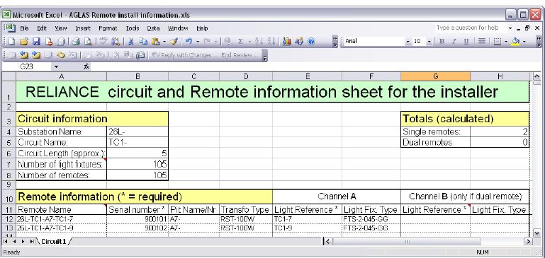
TABLE OF CONTENTS

1.0 Safety.........................................................................................................................................................................................1
     1.1 Safety Messages.......................................................................................................................................................................................................... 1
          1.1.1 Introduction to Safety...................................................................................................................................................................................2
          1.1.2 Intended Use.................................................................................................................................................................................................... 2
          1.1.3 Material Handling Precautions: Storage................................................................................................................................................ 3
          1.1.4 Maintenance Safety....................................................................................................................................................................................... 3
          1.1.5 Arc Flash and Electric Shock Hazard........................................................................................................................................................3
2.0 RELIANCE Remote.................................................................................................................................................................... 5
    2.1 Manual Introduction...................................................................................................................................................................................................5
         2.1.1 How to work with the manual................................................................................................................................................................... 5
         2.1.2 Terms....................................................................................................................................................................................................................5
    2.2 AGLAS Remote Introduction...................................................................................................................................................................................6
         2.2.1 Individual Lamp Control &                                Monitoring System .......................................................................................................................6
         2.2.2 General............................................................................................................................................................................................................. 10
         2.2.3 Illustration....................................................................................................................................................................................................... 11
         2.2.4 Checking the Device....................................................................................................................................................................................11
         2.2.5 View of the device with connections....................................................................................................................................................12
         2.2.6 View of the device with connections....................................................................................................................................................13
         2.2.7 Theory of Operation....................................................................................................................................................................................14
3.0 Installation.............................................................................................................................................................................. 17
     3.1 Installation in a Transformer Pit...........................................................................................................................................................................17
     3.2 Connection to the Series Transformer and the Light Fitting(s)...............................................................................................................18
     3.3 Utility Remote Enclosure Wiring Diagram.......................................................................................................................................................20
     3.4 Earth Grounding........................................................................................................................................................................................................21
     3.5 Safety Instructions.................................................................................................................................................................................................... 21
     3.6 Replacing an RELIANCE Remote......................................................................................................................................................................... 21
4.0 Modes of Operation of an RELIANCE Remote.................................................................................................................... 23
    4.1 Frequency Scan..........................................................................................................................................................................................................23
    4.2 Operating Mode........................................................................................................................................................................................................23
         4.2.1 Self-test Mode............................................................................................................................................................................................... 23
    4.3 Switch Status of the Connected Lights.............................................................................................................................................................23
    4.4 Switch Status under Special Circumstances....................................................................................................................................................24
         4.4.1 Power-up Mode............................................................................................................................................................................................ 24
         4.4.2 Fail-safe Mode...............................................................................................................................................................................................24
         4.4.3 Delayed Start/Stop.......................................................................................................................................................................................24
    4.5 Spreadsheet................................................................................................................................................................................................................ 25
         4.5.1 A sample spreadsheet would contain:................................................................................................................................................. 25
5.0 Parts.........................................................................................................................................................................................27
     5.1 Spare Components...................................................................................................................................................................................................27
A.0 SUPPORT................................................................................................................................................................................ 29
    A.1 ADB SAFEGATE website..........................................................................................................................................................................................29
    A.2 Recycling......................................................................................................................................................................................................................30
         A.2.1 Local authority recycling...........................................................................................................................................................................30
         A.2.2 ADB SAFEGATE recycling.......................................................................................................................................................................... 30

96A0481, Rev. B, 2019/10/01                                                                                                                                                                                                            v
Copyright © ADB Safegate, All Rights Reserved
RELIANCE-C Remote Control Device
TABLE OF CONTENTS

vi
Copyright © ADB Safegate, All Rights Reserved
1.0 Safety
Introduction to Safety

This section contains general safety instructions for installing and using ADB SAFEGATE equipment. Some safety instructions
may not apply to the equipment in this manual. Task- and equipment-specific warnings are included in other sections of this
manual where appropriate.

1.1 Safety Messages

HAZARD Icons used in the manual

For all HAZARD symbols in use, see the Safety section. All symbols must comply with ISO and ANSI standards.
Carefully read and observe all safety instructions in this manual, which alert you to safety hazards and conditions that may
result in personal injury, death or property and equipment damage and are accompanied by the symbol shown below.

                    WARNING
                    Failure to observe a warning may result in personal injury, death or equipment damage.

                    DANGER - Risk of electrical shock or ARC FLASH
                    Disconnect equipment from line voltage. Failure to observe this warning may result in personal injury, death, or
                    equipment damage. ARC Flash may cause blindness, severe burns or death.

                    WARNING - Wear personal protective equipment
                    Failure to observe may result in serious injury.

                    WARNING - Do not touch
                    Failure to observe this warning may result in personal injury, death, or equipment damage.

                    CAUTION
                    Failure to observe a caution may result in equipment damage.

Qualified Personnel

                    Important Information
                    The term qualified personnel is defined here as individuals who thoroughly understand the equipment and its safe
                    operation, maintenance and repair. Qualified personnel are physically capable of performing the required tasks, familiar
                    with all relevant safety rules and regulations and have been trained to safely install, operate, maintain and repair the
                    equipment. It is the responsibility of the company operating this equipment to ensure that its personnel meet these
                    requirements.
                    Always use required personal protective equipment (PPE) and follow safe electrical work practice.

96A0481, Rev. B, 2019/10/01                                                                                                                    1
Copyright © ADB Safegate, All Rights Reserved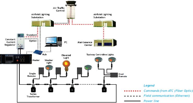
RELIANCE-C Remote Control Device
Safety

1.1.1 Introduction to Safety

                   CAUTION
                   Unsafe Equipment Use
                   This equipment may contain electrostatic devices, hazardous voltages and sharp edges on components
                   •    Read installation instructions in their entirety before starting installation.
                   •    Become familiar with the general safety instructions in this section of the manual before installing,
                        operating, maintaining or repairing this equipment.
                   •    Read and carefully follow the instructions throughout this manual for performing specific tasks and
                        working with specific equipment.
                   •    Make this manual available to personnel installing, operating, maintaining or repairing this
                        equipment.
                   •    Follow all applicable safety procedures required by your company, industry standards and
                        government or other regulatory agencies.
                   •    Install all electrical connections to local code.
                   •    Use only electrical wire of sufficient gauge and insulation to handle the rated current demand. All
                        wiring must meet local codes.
                   •    Route electrical wiring along a protected path. Make sure they will not be damaged by moving
                        equipment.
                   •    Protect components from damage, wear, and harsh environment conditions.
                   •    Allow ample room for maintenance, panel accessibility, and cover removal.
                   •    Protect equipment with safety devices as specified by applicable safety regulations
                   •    If safety devices must be removed for installation, install them immediately after the work is
                        completed and check them for proper functioning prior to returning power to the circuit.

                   Failure to follow this instruction can result in serious injury or equipment damage

Additional Reference Materials

                    Important Information

                    •   IEC - International Standards and Conformity Assessment for all electrical, electronic and related technologies.

                    •   IEC 60364 - Electrical Installations in Buildings.

                    •   FAA Advisory: AC 150/5340-26 (current edition), Maintenance of Airport Visual Aid Facilities.

                    •   Maintenance personnel must refer to the maintenance procedure described in the ICAO Airport Services Manual,
                        Part 9.

                    •   ANSI/NFPA 79, Electrical Standards for Metalworking Machine Tools.

                    •   National and local electrical codes and standards.

1.1.2 Intended Use

                   CAUTION
                   Use this equipment as intended by the manufacturer
                   This equipment is designed to perform a specific function, do not use this equipment for other purposes

                   •    Using this equipment in ways other than described in this manual may result in personal injury, death
                        or property and equipment damage. Use this equipment only as described in this manual.

                   Failure to follow this instruction can result in serious injury or equipment damage

2
Copyright © ADB Safegate, All Rights Reserved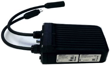
1.1.3 Material Handling Precautions: Storage

                   CAUTION
                   Improper Storage
                   Store this equipment properly
                   •   If equipment is to be stored prior to installation, it must be protected from the weather and kept free
                       of condensation and dust.

                   Failure to follow this instruction can result in equipment damage

1.1.4 Maintenance Safety

                   DANGER
                   Electric Shock Hazard
                   This equipment may contain electrostatic devices

                   •   Do not operate a system that contains malfunctioning components. If a component malfunctions,
                       turn the system OFF immediately.
                   •   Disconnect and lock out electrical power.
                   •   Allow only qualified personnel to make repairs. Repair or replace the malfunctioning component
                       according to instructions provided in its manual.

                   Failure to follow these instructions can result in death or equipment damage

1.1.5 Arc Flash and Electric Shock Hazard

                   DANGER
                   Series Circuits have Hazardous Voltages
                   This equipment produces high voltages to maintain the specified current - Do NOT Disconnect while
                   energized.

                   •   Allow only qualified personnel to perform maintenance, troubleshooting, and repair tasks.
                   •   Only persons who are properly trained and familiar with ADB SAFEGATE equipment are permitted to
                       service this equipment.
                   •   An open airfield current circuit is capable of generating >5000 Vac and may appear OFF to a meter.
                   •   Never unplug a device from a constant current circuit while it is operating; Arc flash may result.
                   •   Disconnect and lock out electrical power.
                   •   Always use safety devices when working on this equipment.
                   •   Follow the recommended maintenance procedures in the product manuals.
                   •   Do not service or adjust any equipment unless another person trained in first aid and CPR is present.
                   •   Connect all disconnected equipment ground cables and wires after servicing equipment. Ground all
                       conductive equipment.
                   •   Use only approved ADB SAFEGATE replacement parts. Using unapproved parts or making
                       unapproved modifications to equipment may void agency approvals and create safety hazards.
                   •   Check the interlock systems periodically to ensure their effectiveness.
                   •   Do not attempt to service electrical equipment if standing water is present. Use caution when
                       servicing electrical equipment in a high-humidity environment.
                   •   Use tools with insulated handles when working with airfield electrical equipment.

                   Failure to follow these instructions can result in death or equipment damage

96A0481, Rev. B, 2019/10/01                                                                                                      3
Copyright © ADB Safegate, All Rights Reserved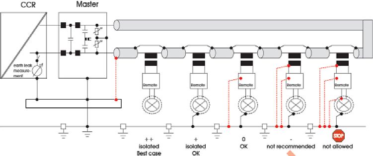
RELIANCE-C Remote Control Device
Safety

4
Copyright © ADB Safegate, All Rights Reserved
2.0 RELIANCE Remote
Reliance™ Remotes – User Manual
General notice: other product names used here are for identification purposes only and may be trademarks of their respective
companies.
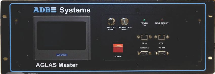
Master Remote
2.1 Manual Introduction
• This document provides detailed information how to correctly install and maintain Airfield Ground Lighting Automation
System RELIANCE remotes.
2.1.1 How to work with the manual
1. Be familiar with the structure and content.
2. Carry out the actions completely and in the given sequence.
2.1.2 Terms
General Aviation Terms and Acronyms that you may encounter using our manuals.
Table 1: Terms
Term Definition
Acronym for Airfield Lighting Control Monitoring System. An ALCMS
incorporates many components that are used to control and monitor
an airport’s entire airfield lighting system. The ALCMS may include
ALCMS
Touch Screens for lighting control, Maintenance Center(s) for data
viewing and archiving, Electrical Lighting equipment for CCR control
and monitoring.
Abbreviation for Constant Current Regulator. The CCRs are located
within the Airfield Lighting Vault (ALV). They produce a constant
CCR
current output to the airfield series circuit that light the airfield
lighting fixtures.
ADB SAFEGATE’s trademarked abbreviation for Airfield Ground
Lighting Automation System which is a term that describes the
Reliance™ Remore, Master, PC
technology used to transmit and receive data across airfield lighting
series circuit cabling.
Unit installed in the airfield (normally in pull-pits or base cans) which
provides control and monitoring of individual or blocks of light
Remote
fixtures. Each Remote has its own unique address for control and
monitoring data communication to the Master.
96A0481, Rev. B, 2019/10/01 5
Copyright © ADB Safegate, All Rights ReservedRELIANCE-C Remote Control Device
RELIANCE Remote
Table 1: Terms (continued)
Term Definition
Unit installed within the lighting vault that provides the means for
data communication on the airfield series circuit cables. The Master
Master is connected in parallel (across) to the output of the CCR. Each series
circuit that contains Remotes must also have a Master installed at the
CCR.
This term is used to reference the device used to control and monitor
the controllable stopbars and the associated lighting equipment. The
Control Panel control panel could be either an L-821 style pushbutton panel or a
Touchscreen style control panel. The control panel is located in the
Air Traffic Control Tower cab.
Acronym which means Surface Movement Guidance and Control
SMGCS System. SMGCS is an organized system created to improve and
enhance low visibility operations.
2.2 AGLAS Remote Introduction
2.2.1 Individual Lamp Control & Monitoring System
Compliance with Standards
FAA: Approved for use with SMGCS Systems. This includes both Stop Bar and Runway Guard Light control/monitoring
according to AC 150/5340-28 (Current Edition); manufactured to AC 120-57 (Current Edition).
ICAO: Complies with CAT I/II/III ICAO lamp supervision requirements. Supports A-SMGCS for enhanced aircraft guidance in all
weather conditions. Supports safety of airport operations by integration in runway safety nets.
IEC: Developed in accordance with IEC 61508
Introduction
The RELIANCE® Intelligent Lighting (IL) is ADB SAFEGATE's state-of-the art individual lamp control and monitoring system.
RELIANCE Intelligent Lighting provides a radical leap in performance over prior airfield power line carrier systems. The system
is designed to communicate on the existing airfield series circuit power line without requiring separate dedicated cabling.
Uses
RELIANCE Intelligent Lighting provides distributed intelligence in the airfield to control and monitor a variety of airfield
lighting devices. It can be used in the following applications:
• Key component of (Advanced-) Surface Movement Guidance Control Systems: (A-)SMGCS
• Stop bar control and monitoring: taxiway routing support.
• Elevated and in-pavement Runway Guard Light (RGL) control and monitoring, CAT II/III monitoring support.
• Failed-lamp detection and location identification.
• Interface with aircraft/vehicle presence sensors (option).
• Selective control and monitoring of various airfield lighting devices.
The system provides relevant information concerning the status of connected airfield lighting devices to both airport
maintenance and air traffic control personnel.
6
Copyright © ADB Safegate, All Rights ReservedFurthermore RELIANCE Intelligent Lighting: • Supports the optimization of traffic volume, flexibility, maintainability and airside safety. • Ensures reliable guidance for aircraft on the ground during CAT I, II or III conditions, increasing safety and reducing the risk of runway incursions. • Automatically detects and reports lamp failures, decreasing downtime and maintenance costs. Customer Benefits • Faster, predictable and more robust power line carrier communication method ensures highest reliability even for long airfield circuits that contain large number of lamps. • Increased number of slots per day as a result of higher traffic throughput and better control of ground traffic movements. • Flexible routing functionality and safe operation under all traffic and environmental conditions resulting in reduced ATC workload. • Precise control of each segment of runways, taxiways, and stop bar lighting. • Adjacent lamp failure reporting. • Most economic solution for modernization projects through power line communication on existing circuits. • Easy future upgrade of installed RELIANCE Intelligent Lighting systems. • A step-by-step migration strategy can then be implemented. • Optimized planning of runway and taxiway maintenance downtimes. • Worldwide availability of our regional Technical Service staff for technical support and site services on short notice. RELIANCE Intelligent Lighting Platform II Technology • Communicates using a radio frequency signal imposed on the high- voltage airfield series circuit cable - no separate communication cable needed. • Communication quality is automatically optimized for each series circuit in a permanent background process. • New communication principle together with forward error correction drastically reduces signal disturbance caused by impulse and narrow band interferences. • Main system elements: RELIANCE IL Master (in the substation), RELIANCE IL Remotes (for individual control and monitoring of lights in the field). In addition, RELIANCE IL Utility Remote for communication with and energy supply for local field sensors. Features • No separate communication cable required. RF signal on high voltage power cable for lighting control. • Most cost-effective and proven solution for existing ground lighting systems. • User friendly integrated web server allows easy operation and system status recognition. • Up to 11 different frequency bands can be used in parallel, and up to 32 different timeslots which allow an increase in the number of independent communication channels up to 176. • Fast and predictable switching times through the use of reliable communication methods and limited repeater levels. • Synchronizing of control systems in different vaults by Ethernet in compliance with IEEE 1588. • Single Frequency Network system includes an automatic network configuration function. This functionality provides for dynamic communication adaptation in all environmental conditions (such as humidity variation). The system dynamically checks repeater settings and automatically sets them, even if a Remote in the communication path has failed. • Less crosstalk due to symmetrical design of coupling components (transmit and receive path), independent communication channels and lower transmission power compared to similar systems in the market. • Can be used as a stand-alone monitoring system or integrated with an ALCS (Airfield Lighting Control System). 96A0481, Rev. B, 2019/10/01 7 Copyright © ADB Safegate, All Rights Reserved
RELIANCE-C Remote Control Device
RELIANCE Remote

• Individual control of different functions in one lamp circuit. For example, a combination of Stop Bar and Lead-In Circuit.
• Optional Runway Guard Light Remotes, automatic start and net-synchronous Wig-Wag operation, independent from
   Master meeting FAA requirements.
• Firmware and application software can be downloaded into either the Master (substation) or Remotes (field units).
• State-of-the-art diagnostic tools provide a quick overview about communication behavior. Network management system
   provides detailed routing statistics to ensure reliable communication quality.
• Communication measurements can be taken in advance within one day to analyze existing airfield infrastructure.
• Field sensors can be integrated via Utility Remotes into the RELIANCE Intelligent Lighting lamp control and monitoring
   circuit for detection and transmission of local surveillance information via power line communication.
• Able to work with any kind of CCR and designed for 40 Ampere peak current.

Main Characteristics and Figures

• Up to 300 Remotes per circuit, providing a potential of 600 individually addressable lights per circuit.
• Up to 20 km roundtrip circuit length.
• Configurable block evaluation modes include full feedback, small sample feedback, and optimistic feedback.
• Can command 10 blocks to 10 distinct states with one power-line message. Can command all blocks to one state with one
   powerline message.
• Switches up to 120 lights in 10 different groups in less than 1 second.
• Switches 5 stopbar/lead-on lights simultaneously and presents real-back indication in less than 1 second.
• Status poll provides detailed Remote and lamp parameters.

Integrated System Control

Overall system configuration and control is realized via a control process with integrated web server for configuration and
maintenance.

• Each circuit is equipped with a microprocessor-controlled Master for tracking, recording and management of state of all
   Remotes in the circuit.
• The Master communicates with all the Remotes (not light fixtures) in a circuit and polls all lamps independent from the
   control system.

Overall System Specifications

Description                                     Remote                                Master

Operating temperature                           -40 °C to +65 °C                      0 °C to +55 °C

Storage temperature                             -55 °C to +85 °C                      -40 °C to +75 °C

Operating humidity                              Max. 100 %                            Max. 95 % non condensing

Series circuit operating voltage                                      -               Max. 5000 V AC RMS

Min. / max. Power line current                  1.8 up to 6.9 A RMS                   1.8 up to 6.9 A RMS

Series circuit peak voltage                                           -               Max. 15 kV

Maximum switching power secondary side of 300 W (single Remote) Ch A + Ch B < 300 W                          -
transformer                               (dual)

Maximum circuit load (CCR power)                                      -               30 kVA

Power consumption                               Max. 8 W at 6.6 A                     Max. 15 W for power supply 115-230 V Max.
                                                                                      65 W on primary circuit at 6.6 A

8
Copyright © ADB Safegate, All Rights Reserved
Description Remote Master
Enclosure protection level IP 68 / NEMA 6 P IP 20
LAN connection to upper control system - IEEE 802.3 100 BaseT / IEEE1588 PTP
Net voltage of power supply - 115 - 230 V AC ±15 %, 50/60 Hz
MTBF > 200.000 h > 200.000 h
Indicative MTTR < 30 min < 60 min
Lightning protection 20 kA (8/20 micro sec.) 17 kA (8/20 micro sec.)
Description Remote Master
EMC (CE approved) Compliant to the EN 61000-6-4 (EMC emission standard)
Compliant to the EN 61000-6-2 and 6-5 (EMC immunity standard)
Compliant to the 60950 (IT equipment standard)
Power Up Mode On; Off; Flashing; Maintained (last commanded state)
Fail-Safe Mode On; Off; Flashing, Maintained (last commanded state)
Number of controlled and monitored lamps 1 or 2 Up to 300 Remotes or 600 lights, if dual
per unit Remotes are used
Number of I/O Remotes per circuit - Max. 16
Transmit Frequency 11 different frequency bands between 20 kHz and 200 kHz
Data transmission rate power line Up to 8 kbps Up to 8 kbps
Description Remote Master
Dimensions (W x H x D) / Weight 208 x 78 x 142 / 2.2 kg (single Remote) / 2.3 435.8 x 177.5 x 421.5mm / 22.3 kg
kg (dual)
Lamp failure reaction Short is placed across isolation transformer -
as soon as lamp flament failure detected
Power Storage after Power-Off Remote does not reset and remains in -
operation, if circuit power loss < 1.5 sec.
Remote start up time is less than 1 sec.
Circuit Specifications
Cable type L-824 is recommended, for example FLYCY or equivalent. The following parameters (∗) represent the specific
characteristic needed in an equivalent L-824 cable. Reuse of existing installations and layout with maximum cable length or
number of lights to be verified.
Cable type (specification) L-824
Capacity of the cableRELIANCE-C Remote Control Device
RELIANCE Remote
System Overview
Air Traffic
Control
Airfield Lighting Airfield Lighting
Substation Substation
Standard
Constant
Option
Current PC Maintenance
Regulator Center
Hub Elevated Taxiway Centerline Lights
Lights
Master Stopbar
Lights
Single Dual
Remote Remote
Legend
Commands from ATC (Fiber Optic)
Series
Transformer
Field communication (Ethernet)
Power line
Ordering Code: Masters
RELIANCE IL Master, 19″ Rack Mount AGC1110
RELIANCE IL Master, Wall Mount, Door Open Left AGC2110
RELIANCE IL Master, Wall Mount, Door Open Right AGC3110
Ordering Code: Remotes
RELIANCE IL Single Channel Remote, FAA Style 7 AGC4170
RELIANCE IL Single Channel Remote, FAA Style 8 AGC4180
RELIANCE IL Single Channel Remote, FAA Style 7, Initial Flash Off AGC4270
RELIANCE IL Single Channel Remote, FAA Style 7, Initial Flash On AGC4370
RELIANCE IL Dual Channel Remote, FAA Style 7 AGC5170
RELIANCE IL Dual Channel Remote, FAA Style 7, Channel A Initial Flash On, Channel B Initial Flash Off AGC5470
RELIANCE IL Utility Remote AGC6110
2.2.2 General
The RELIANCE Remotes are intelligent powerline addressable field devices that operate on the secondary side of airfield
isolation transformers. They serve as slave nodes in a master/slave network that is controlled by a RELIANCE Master. The
RELIANCE Remote is available in the following four versions:
• RELIANCE Remote single channel for controlling one light (airfield ground lighting)
• RELIANCE Remote dual channel for controlling two lights (airfield ground lighting)
10
Copyright © ADB Safegate, All Rights Reserved• RELIANCE Remote RGL single channel for network-synchronized blinking after switching on, without master synchronization (Runway Guard Light) • RELIANCE Remote RGL dual channel for continuous, network-synchronized, alternating blinking of both channels after switching on, without master synchronization (Runway Guard Light) In terms of construction, they differ in the number of channels which in turn determines the number of lights that can be switched. RGL Remotes leave the factory with a special configuration that ensures synchronous start-up after power-up of the regulator and network-synchronized blinking without master synchronization. The factory setting also includes the choice whether the blinking is to start with “initial flash On” or “Off”. This option makes it possible to have different groups of Remotes flash alternately, leveling the load on the constant current regulator caused by synchronous switching of all groups of Remotes. In the following sections all four devices will be referred to as AGLAS Remotes. 2.2.3 Illustration Figure 1: RELIANCE Remote single 2.2.4 Checking the Device 2.2.4.1 Scope of Supply The RELIANCE-C Remote single channel is supplied with two 12-inch (30 cm) cord-set cables for connection to the series transformer and the light. The RELIANCE-C Remote dual channel is supplied with three 12-inch (30 cm) cord-set cables, 1 for connection to the series transformer and 2 for connection to the lights. The RELIANCE-C Remote single channel RGL is supplied with two 12-inch (30 cm) cord-set cables for connection to the series transformer and the light, adjusted at the factory for configured start-up after switching on (consistent adjustment for all RGL Remotes in a project). The RELIANCE-C Remote dual channel RGL is supplied with three 12-inch (30 cm) cord-set cables, 1 for connection to the series transformer and 2 for connection to the lights; adjusted at the factory for configured start-up after switching on. See Parts for the complete list of remote variants. 2.2.4.2 Unpacking The device has been fully assembled, tested and packed at the factory and has no internal transport locks. 2.2.4.3 Inspection The delivery must be checked to make sure that it is complete and in perfect condition. The supplier must be notified of any complaints within 2 weeks. After this period, complaints about the delivery will not be accepted. In the event of the goods being returned, the same transport packaging must be used. See Figure 2. The number on the nameplate must be checked against the order number on the delivery note. 96A0481, Rev. B, 2019/10/01 11 Copyright © ADB Safegate, All Rights Reserved
RELIANCE-C Remote Control Device
RELIANCE Remote
The nameplate is located on the side of the device (example: RELIANCE-C Remote single channel).
Figure 2: Nameplate of the RELIANCE Remote Duel Channel
For commissioning, the serial number on the nameplate (e.g. serial number 4015000220, see Figure 2) must be recorded. This
is then utilized for installation and configuration.
2.2.4.4 Storage
When storing the device, it is advisable to leave it in its original packaging. The storage temperature is shown in “Technical
Specifications”.
Storage Temperature: Remote: -67°F to +167°F (-55°C to +75°C)
2.2.5 View of the device with connections
Figure 3: View of the RELIANCE Remote Dual Channel
5. Reliance Remote, Dual Channel
X1
X4
X3
4. Ground Screw 6. Remote ID Label
X2
1. Cable with 2-pin plug (in compliance with FAA L-823) for connection to the series circuit isolation transformer (X3)
2. Cable with 2-pin socket (in compliance with FAA L-823) for connection to the light on channel A (X1)
3. Cable with 2-pin socket (in compliance with FAA L-823) for connection to the light on channel B (for dual Remote only)
(X4)
4. Ground cable connection (X2)
5. RELIANCE Remote housing
6. RELIANCE Remote Label for Remote ID number.
Note
See nameplate of RELIANCE Remote (Figure 2) for identification of connections marked “X”.
12
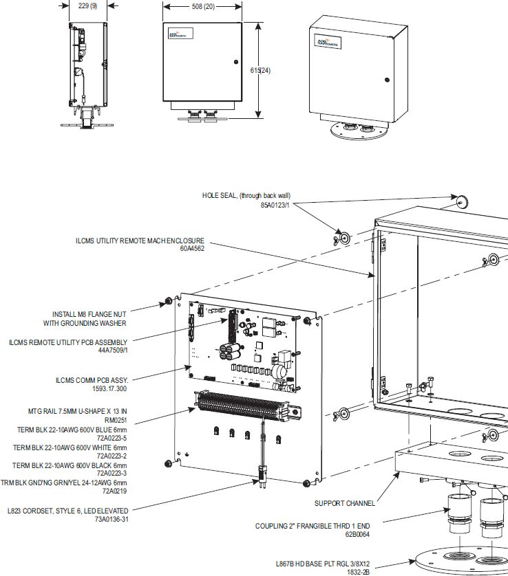
Copyright © ADB Safegate, All Rights Reserved2.2.6 View of the device with connections
Figure 4: View of the RELIANCE Utility Remote Cabinet
Note
See the remote cabinet wiring diagram for connections.
2.2.6.1 Construction
The AGLAS Remote is sealed to make it watertight and gas-tight and must not be opened.
96A0481, Rev. B, 2019/10/01 13
Copyright © ADB Safegate, All Rights ReservedRELIANCE-C Remote Control Device
RELIANCE Remote
Note
Once the Remote has been opened, the warranty is void.
A defective or open Remote must be returned to the manufacturer.
2.2.6.2 Block diagram
Figure 5: Block diagram of the RELIANCE Remote dual
2.2.7 Theory of Operation
Background Information: RELIANCE uses power line carrier technology to communicate between controlling units on an
airfield lighting series circuit. A RELIANCE system typically consists of one high voltage modem, or Master, connected with the
Constant Current Regulator (CCR) powering the airfield lighting circuit and many slave units, or Remotes, collocated with
individual lights in the field. A typical RELIANCE topology is provided in Figure 6.
Figure 6: Typical RELIANCE Topology
14
Copyright © ADB Safegate, All Rights Reserved2.2.7.1 Architecture Figure 7 depicts the general nature of the system components and their interactions. The “Control System”, shown in grey, is an external ALCMS system that provides controlling commands and digests Master and Fixture status reports. There is typically only one control system in the architecture. The “Master”, shown in blue, is the high voltage modem that communicates commands to and receives status from the fixtures. There can be many masters in a given system. Masters digest commands from the control system and provide status to it. Masters also communicate amongst themselves to maintain communication timing synchronization. Each master communicates with the fixtures on its respective circuit. Figure 7: Series Circuit Master / Fixture Architecture 96A0481, Rev. B, 2019/10/01 15 Copyright © ADB Safegate, All Rights Reserved
RELIANCE-C Remote Control Device
RELIANCE Remote

16
Copyright © ADB Safegate, All Rights Reserved
3.0 Installation
Installation is identical for all RELIANCE Remote versions.
Figure 8: Diagram of RELIANCE installation in series circuit

1. Light Fixture                                                 5. Remote Input Plug (TRANSFORMER)

2. Light Fixture Plug                                            6. Transformer Secondary Receptacle

3. Remote Output Receptacle (LAMP)                               7. Primary Series Circuit

4. Remote                                                        8. L-830/L-831 Isolation Transformer

3.1 Installation in a Transformer Pit

The orientation required for installation is indicated by the labeling on the nameplate.
This ensures optimum heat dissipation through the housing. If the device is installed by suspension, free air circulation must
be provided for the RELIANCE Remote.

        Note
        If several RELIANCE Remotes are installed in a single pit, they should be spaced with a distance of at least 2-inch
        (50mm) from each other and from the series transformers to have optimum communication signal separation.
        Because the communication signal is coupled magnetically, the distance between the transformers should also not be
        less than 2-inch (50mm).

Minimum distance between remote cable feed-through and pit walls is 2-inch (50 mm).
Figure 9: Remote max. bending radius

96A0481, Rev. B, 2019/10/01                                                                                                      17
Copyright © ADB Safegate, All Rights Reserved
RELIANCE-C Remote Control Device Installation 3.2 Connection to the Series Transformer and the Light Fitting(s) The 2-pin plug on cable X1 is connected to the socket for the secondary circuit of the series transformer. The light(s) is/are connected to the 2-pin socket(s) of the cable(s) X3 (and X4 for the dual AGLAS Remote). All plug connections must be sealed with self-bonding insulation tape or using “heat shrink” sleeves. To improve watertightness, an optional watertight heat shrink sleeve can be installed at the junction of the plug and receptacle: (see Figure 10) Figure 10: Connection to series transformer and light fitting 1. Place the heat shrink sleeve over the light inset plug wire. 2. Connect the inset light plug to the Remote receptacle designated CHANNEL A (and CHANNEL B if used). 3. Pull the heat shrink sleeve over the plug-to-receptacle connection. Heats shrink the sleeve. 18 Copyright © ADB Safegate, All Rights Reserved
Repeat steps 1 through 3 for the Remote plug designated TRANSFORMER and the transformer secondary receptacle.

96A0481, Rev. B, 2019/10/01                                                                                        19
Copyright © ADB Safegate, All Rights Reserved
RELIANCE-C Remote Control Device
Installation

3.3 Utility Remote Enclosure Wiring Diagram

20
Copyright © ADB Safegate, All Rights Reserved
3.4 Earth Grounding

To protect it against a surge generated by lightning, each RELIANCE Remote should be provided with a separate, low
induction and low resistance ground connection via the ground screw. The ground cable must be connected to the ground
screw by means of a suitable cable lug. The cross-sectional area of the cable should be at least AWG 8 (6 mm2) with a
maximum cable length of 36- inch (1m).
If the isolation value of the earth ground is bad, it is better NOT to connect the remote to earth ground (see Figure 11).
Figure 11: Connection to a series circuit isolation transformer and light fitting

3.5 Safety Instructions

        DANGER
        Read this entire manual prior to starting any work.
        Work on 120/240 V power supply systems or the series circuit must only be carried out by trained, qualified staff. The
        currently applicable regulations according to international standards must be followed. Also see the “Safety” section.

        Note
        The RELIANCE Remote is maintenance free.
        The RELIANCE Remote must never be opened, otherwise warranty will be void.

3.6 Replacing an RELIANCE Remote

 1. In each case, inspect the technical condition of the RELIANCE Remote which has to be removed or replaced, or the
    RELIANCE Remote which is to be installed as a replacement device.
 2. If the old remote is still communicating with the master (can be verified with the RELIANCE Configuration software), it is
    recommended to logout this remote prior to removal.
   Follow the “Logout procedure” procedure as described in “96A0430 RELIANCE Configuration Software User Manual”. If the
   remote is completely dead, Step 2 is not applicable.
 3. Switch off and disconnect the associated series circuit from the incoming power by removing the fuses of the Constant
    Current Regulator (CCR).
 4. Pull out the cut-out for the series circuit, if possible ground the series circuit and wait about 5 minutes until the circuit is
    fully discharged.
 5. Removing a RELIANCE Remote: first, separate the series circuit connections X3 and X1 and, in the case of the dual
    RELIANCE Remote, X4 at the cable plug connections.
   Then, open the ground connection X2 by unscrewing the earth ground screw.

96A0481, Rev. B, 2019/10/01                                                                                                            21
Copyright © ADB Safegate, All Rights Reserved
RELIANCE-C Remote Control Device
Installation
6. Installing a RELIANCE Remote: install the new AGLAS Remote according to the Installation.
7. Switch on the associated series circuit and verify if the replaced remote connected lamp(s) are functioning (for RGL
remotes: blinking).
8. Follow the “change remote” procedure as described in “96A0430 RELIANCE Configuration Software - User Manual” to
make the replaced remote operational.
22
Copyright © ADB Safegate, All Rights Reserved4.0 Modes of Operation of an RELIANCE Remote 4.1 Frequency Scan Initial State on a new remote from the factory. State on delivery On delivery, each new RELIANCE Remote that has not yet been logged on with a RELIANCE Master is in “frequency scan mode”. For power-up mode (“On”), fail-safe mode (“On”) and Delayed Start/Stop (“Off”) it uses the factory settings, which are given here in brackets (default values). RGL//Wig-wag remotes are pre-configured with “Blink” for power-up and fail-safe mode. Base state A RELIANCE Remote that has been logged off from a circuit also reverts to frequency scan mode. However, for power-up mode, fail-safe mode and Delayed Start/Stop it uses the most recent settings received from the RELIANCE Master (most recent configuration). In frequency scan mode, a RELIANCE Remote, when it is installed in a series circuit and the latter is turned on, searches on all frequency bands for a master telegram containing its serial number. If this search is successful, the RELIANCE Remote logs on to the corresponding RELIANCE Master. When an RELIANCE Remote is logged off from a circuit, it reverts to base state. 4.2 Operating Mode After successfully logging on, a RELIANCE Remote automatically switches to “operating mode” (normal operation) and receives its configuration parameters from the RELIANCE Master. All parameters are stored firmly in the AGLAS Remote. In operating mode, all lights connected to the RELIANCE Remotes can be switched independently of each other via single or block commands (i.e. a command switches a predefined group of lights).The switch commands can be “On”, “Off” or “Blink”. When a RELIANCE Remote receives a switch command it returns the message “switch command executed” (block command) or “switch command received” (single command). However, the real status of the lights is only determined at the next status polling by the RELIANCE Master. In the RELIANCE Remote, each switching operation for the light is carried out first via an electronic switch and then via a relay (“blink” mode is established with electronic switch only). Each RELIANCE Remote monitors the status of the lights connected to it (maximum of two lights). The monitoring takes place when the light is switched on by default. Whether the lamp should be monitored in the “Off” state too, is configurable. Once a lamp failure has been detected (“Open”), the light is no longer monitored during this operation period and switch commands for this light are ignored. It will not be checked again until the circuit has been switched off and on again or after the reception of a reset command (software function) from the RELIANCE PC. 4.2.1 Self-test Mode After the series circuit has been switched on, each RELIANCE Remote runs a self-test. If an error is detected through this test, the RELIANCE Remote switches to error mode. This means that communication with a RELIANCE Master is not possible. During normal operation, the remote also checks the switching and high voltage protection devices. If any problem should occur with these devices (after 9 lightning strike for example), a specific error message is sent to the master. 4.3 Switch Status of the Connected Lights One light can be connected to each single channel RELIANCE Remote, and up to two lights (“A” and “B”) can be connected to each dual channel RELIANCE Remote. A light can assume the following types of status: • “Off” (light is switched off and not burning). • “On” (light is switched on and the electric circuit is closed). • “Open” (light is switched on but the electric circuit is not closed, i.e. the light filament is broken or the light is not connected). • “Blink” (light flashing; no information as to whether the light is “On” or “Off” at the time of polling). On the Graphical User Interface (GUI), the status of each light is indicated by the terms given in quotation marks. 96A0481, Rev. B, 2019/10/01 23 Copyright © ADB Safegate, All Rights Reserved
RELIANCE-C Remote Control Device
Modes of Operation of an RELIANCE Remote

4.4 Switch Status under Special Circumstances

With the help of the RELIANCE PC software, the user has to configure each AGLAS Remote of a circuit to which the Remote
shall switch its connected lights:

• When the series circuit is powered up (power-up mode),
• When the communication between the RELIANCE PC and the RELIANCE Master or between the RELIANCE Master and the
   RELIANCE Remote is interrupted (fail-safe mode),
• And if there is to be a Delayed Start/Stop or not (when several lights are switched simultaneously by a block command).

4.4.1 Power-up Mode
The “power-up mode” defines to which status the RELIANCE Remotes should switch their lights directly after power-up of the
series circuit. The parameters of the following types of switch status can be set via the RELIANCE PC:

• “On”.
• “Off”.
• “Blink” (flashing).
• “Last Commanded State” (maintain the last operating status).
This mode ends after a switch command from the RELIANCE Master has been received.

4.4.2 Fail-safe Mode
As soon as the RELIANCE Remote detects a failure of the communication with its RELIANCE Master or receives a failsafe
telegram from it, it switches the connected light(s) into a predefined status. This status can be parameterized via the
RELIANCE PC software as follows:

• “On”.
• “Off”.
• “Blink” (flashing).
• “Last Commanded State” (maintain the last operating status).
The duration of the interval before a communication problem is identified can be configured via the RELIANCE PC software as
well. The failsafe mode is not exited automatically after communication has been restored but only after the RELIANCE
Remote has received a switch command from the RELIANCE Master.

4.4.3 Delayed Start/Stop
When switching several lights via a block command, the lights can be controlled using a defined delay (ms), which can be
configured. This setting ensures constant current regulator stability in case of large load fluctuations. The following
parameters can be set:

• No delayed switching.
• Delayed switch-on/off setting 1 (10ms delay per lamp)
• Delayed switch-on/off setting 2 (20ms delay per lamp)
• Delayed switch-on/off setting 3 (30ms delay per lamp)
• Delayed switch-on/off setting 4 (40ms delay per lamp)
• Delayed switch-on/off setting 5 (50ms delay per lamp)

24
Copyright © ADB Safegate, All Rights Reserved
You can also read