Development of a Novel Omnidirectional Treadmill-Based Locomotion Interface Device with Running Capability
←
→
Page content transcription
If your browser does not render page correctly, please read the page content below
applied
              sciences
Article
Development of a Novel Omnidirectional Treadmill-Based
Locomotion Interface Device with Running Capability
Sanghun Pyo             , Hosu Lee and Jungwon Yoon *

                                          Integrated Institute of Technology, Gwangju Institute of Science and Technology (GIST), 123 Cheomdan-gwagiro,
                                          Buk-gu, Gwangju 61005, Korea; pyopyo83@gist.ac.kr (S.P.); lakelee77@gist.ac.kr (H.L.)
                                          * Correspondence: jyoon@gist.ac.kr

                                          Abstract: To achieve an immersive virtual reality (VR) environment, omnidirectional treadmills
                                          (ODTs) allow users to perform locomotion in any direction. However, existing ODTs are heavy and
                                          complex, and operate at low speeds. This limits fast user motion and prevents natural interactions
                                          in real applications such as military training programs and interactive games. In this paper, we
                                          introduce a novel locomotion interface device with running capability, which uses an omnidirectional
                                          treadmill with a new power transmission mechanism and a locomotion controller that enables the
                                          user to make fast movements. As a result of the improved power transmission performance due
                                          to the simple and relatively lightweight structure, the proposed two-dimensional treadmill can
                                          generate a maximum speed of 3 m/s, with an acceleration of 3 m/s2 . Moreover, through a pilot test
                                          with the proposed locomotion interface device, we verified that the fast directional changes during
                                          walking and running with the designed speed adaptation controller do not exceed the acceleration
                                          performance of the proposed system. Due to its wide range of movement speeds and acceleration
                                capabilities, and lack of any motion constraints, the proposed locomotion interface device with a

                                          novel ODT can be used as a representative platform in various VR environments to enhance the
Citation: Pyo, S.; Lee, H.; Yoon, J.
                                          immersive experience.
Development of a Novel
Omnidirectional Treadmill-Based
                                          Keywords: human-machine interfaces; modeling and design of mechatronics systems; virtual reality
Locomotion Interface Device with
                                          and human interface
Running Capability. Appl. Sci. 2021,
11, 4223. https://doi.org/10.3390/
app11094223

                                          1. Introduction
Academic Editor: Yuichi Kurita
                                               A locomotion interface (LI) can support walking and running through appropriately
Received: 23 March 2021                   generated ground surfaces to provide active participation in virtual environments (VEs)
Accepted: 3 May 2021                      with realistic spatial sensations [1]. Therefore, an LI provides a sense of mobility based on
Published: 6 May 2021                     energy input/consumption of actual walking [2]. To create more immersive locomotion, a
                                          LI system should allow the user to arbitrarily change not only the walking speed, but also
Publisher’s Note: MDPI stays neutral      the walking direction. Such features may motivate a user to participate more actively in
with regard to jurisdictional claims in   VR experiences, such as military training programs, physical education programs, disaster
published maps and institutional affil-   preparedness training, and rehabilitation programs [3].
iations.                                       To simulate omnidirectional locomotion, several types of devices have been suggested,
                                          such as balls [4], large spheres [5], mobile robots [6], a rotating one-dimensional (1D) tread-
                                          mill [7], and a robotic foot platform [8–10]. However, these devices have limitations with
                                          respect to omnidirectional walking. As the most natural mechanism for two-dimensional
Copyright: © 2021 by the authors.         (2D) LI, an omnidirectional treadmill (ODT) can simulate the over-ground walking of
Licensee MDPI, Basel, Switzerland.        humans [11–13]. An ODT or 2D treadmill usually consists of “unit segments” (transverse
This article is an open access article    treadmills) installed in such a way as to form a continuous loop (Figure 1). Each unit
distributed under the terms and           segment is a narrow treadmill with its own belt.
conditions of the Creative Commons
Attribution (CC BY) license (https://
creativecommons.org/licenses/by/
4.0/).

Appl. Sci. 2021, 11, 4223. https://doi.org/10.3390/app11094223                                               https://www.mdpi.com/journal/applsci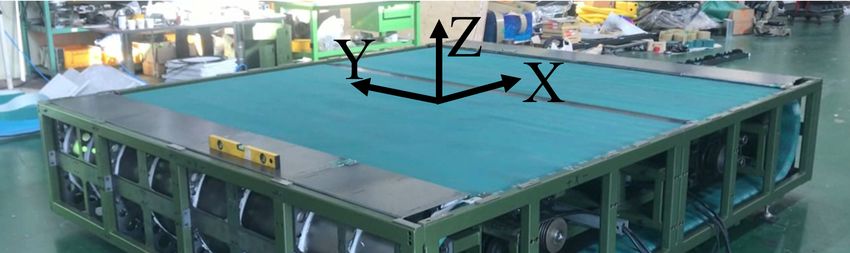
Appl.
Sci. 2021, 11, Sci. 2021,
x FOR PEER11, 4223
REVIEW 2 of 20 2 of 20
Appl. Sci. 2021, 11, x FOR PEER REVIEW 3 of 20
the following capabilities: (1) X- and Y-axis translational motion generation through a
novel gear-based power transmission mechanism; (2) a distributed power scheme in
which two motors installed on each axis are synchronized using low-level synchronized
motor control [17]; and (3) high-level feedback using robust integral of the sign of the error
(RISE) control [18] to allow fast movements while changing the walking direction.
The remainder of the paper is organized as follows; the main design concepts for the
locomotion interface device with high speed and acceleration are presented in Section 2,
the high-level controller design for the proposed locomotion interface and pilot study re-
sults are in Sections 3 and 4. Finally, the conclusions drawn are given in Section 5.
2. LI Device Design for Fast Motion
2.1. Actuation of Unit Segment Belt by Geared Transmission
For 2D treadmills, the main issue is how to actuate the segment belt for Y-axis motion.
In Torus and Cyberwalk treadmills, as shown in Figure 2a, each segment requires a dedi-
Figure 1. Omnidirectional
Figure 1. Omnidirectional treadmill (ODT)treadmill
cated actuator, concept
which(ODT)
(see concept
Figure
increases (see
2the
for Figure
the 2 mass
for thedue
cross-sectional
segment cross-sectional
view), theview),
gearedand
andinclusion
to the omni-pulley
of the actuating
the geared omni-pulley
(GOP)-based actuation scheme of and
parts (GOP)-based
the proposed actuation
ODTitto
thus makes scheme
a generate of the proposed
infinite 2Ddesign
disadvantageous ODT to generate infinite
ground.for implementing fast X-axis motion.
2D ground.
In an ODT, as shown in Figure 1, the X-axis translational motion is generated by the
rotation of all the unit segments along AX vector, while the Y-axis translational motion is
generated by rotational actuation of the belt of each segment along AY vector. Thus, the
2D treadmill combines small treadmills assembled orthogonally to create a single, large
treadmill. An ODT provides an infinite ground plane by generating independent belt mo-
tions along two orthogonal axes (X and Y). In the cases of Cyberwalk [12] and Torus tread-
mill [14], Y-axis translational motion is generated by individual actuators attached directly
to each unit segment. This increases the inertia of the segments; thus, this design requires
a very large amount of power to rotate all the segments (X-axis motion). As the weight of
each segment is increased, the acceleration performance is greatly reduced.
The ODTs developed by the United States Army Research Institute (US ARL) ODT
[15] and the InfinaDeck treadmill [16] use a different mechanism to generate Y-axis mo-
tion. The transverse treadmill belt (segment belt) is actuated by stationary actuator(s)
through a special transmission system. This design, due to the light weight of the individ-
ual segments, may improve the maximum speed and acceleration of the systems during
X-axis translational motion as compared to those of the Cyberwalk and Torus treadmill.
To drive each segment belt while allowing free movement in the X-axis direction, these
ODTs use a frictional
Figure transmission mechanism composed of omni-wheels. However, since Transver-
Figure2. 2.Cross-sectional
Cross-sectionalview view ofof the
the Y-axis
Y-axis motion of a 2D treadmill (unit segment): (a) Transversal
the omni-wheels-based
sal treadmill frictional
actuated transmission
directly by actuatormechanism
an actuator (Torus has a low power
or Cyberwalk transmission
treadmill), (b) Frictional trans-
treadmill actuated directly by an (Torus or Cyberwalk treadmill), (b) Frictional transmission
efficiency, the maximum
mission speed
mechanism and
based acceleration
on the Omni-wheel of these ODTs for
via the frame-fixed Y-axis
motor translational
(US army(c)
ODT), (c) The
mechanism based on the Omni-wheel via the frame-fixed motor (US army ODT), The proposed
motion are limited.
proposed Thus, due tobased
mechanism the high inertia of the
on gear-driven unit segment
transmission via a treadmills
frame-fixed for X-axis
motor.
mechanism based on gear-driven transmission via a frame-fixed motor.
translational motion and the low efficiency of power transmission for Y-axis translational
motion, the currently In
In the US ARL
anavailable
ODT, as 2D ODT
shown (United
treadmills
in FigureareStates
1,only Army
the able
X-axis Research Laboratory
to translational
accommodate is Omnidirectional
slow human
motion generated by the
Treadmill), as shown in Figure 2b, a motor→ attached to theinsystem framean can drive the
walking speeds and accelerations. This limitation is the main obstacle
rotation of all the unit segments along AX vector, while the Y-axis translational motion isdeveloping
immersive VR segment belt through
environment an and
with fast omni-wheel-based
natural locomotion. power transmission mechanism. → The power
A further generated
fromcomplexity by inrotational
the frame-fixedthe design actuation
motor can
of beoftransmitted
a past the belt
paced ODTof each
to
is thesegment
that segment
even afteralong
belt AYY-axis
for
improvingvector.motion
Thus, the
by
2D
the treadmill
omni-wheels, combines
while small
the treadmills
rollers of the assembled
omni-wheels
the power transmission efficiency for Y-axis motion and reducing the mass of moving orthogonally
that are in to
contactcreate
witha single,
the large
segment
componentsbelt treadmill.
for passively Anrotate
X-axis motion, ODTthe provides
when an scheme
infinite
the segments
actuation ground
move along
of the plane
ODT X-axis.by This
must generating independent
transmission
be carefully de- is basedbelt on
motions
line–contact along two
friction, orthogonal
which axes
limits frame;(X and
the ability Y). In the
of the segmentcases of Cyberwalk
belt should
to follow [12]fast
the andmove-
Torus
signed to reduce structural stress in the ODT’s additionally, the design min-
treadmillof a [14], Y-axis translational motion theistransmission
generated byefficiency
individual of actuators attached
imize energymentsloss from user along Y-axis.
the actuators to theTopower
enhance transfer components during motor segment
ac- belt actu-
directly to each unit segment. This increases the inertia of the segments; thus, this design
tuation. ation, we propose the novel gear transmission method shown in Figure 2c to directly drive
requires a very large amount of power to rotate all the segments (X-axis motion). As the
each segment
In this study, we have belt [19]. Since
developed the locomotion
a novel segment belts are driven
interface device, bywhich
geared-pulleys,
is based the trans-
weight of each segment is increased, the acceleration performance is greatly reduced.
mission efficiency
on an omnidirectional treadmill is with
significantly enhanced
a transmission as compared
mechanism that to the frictional
is referred to as transmission
the by
The ODTs developed by the United States Army Research Institute (US ARL) ODT [15]
an omni-wheel.
geared omni-pulley (GOP). To Moreover,
overcome thetheproposed
limitations concept is suitable ODTs
of conventional to generate
and tofast X-axis motion
deal
and the InfinaDeck treadmill [16] use a different mechanism to generate Y-axis motion.
due to a lightweight
with the complexities of fast ODT platform
design, with low segment
the proposed mass/inertia.
locomotion interface device has
The transverse treadmill belt (segment belt) is actuated by stationary actuator(s) through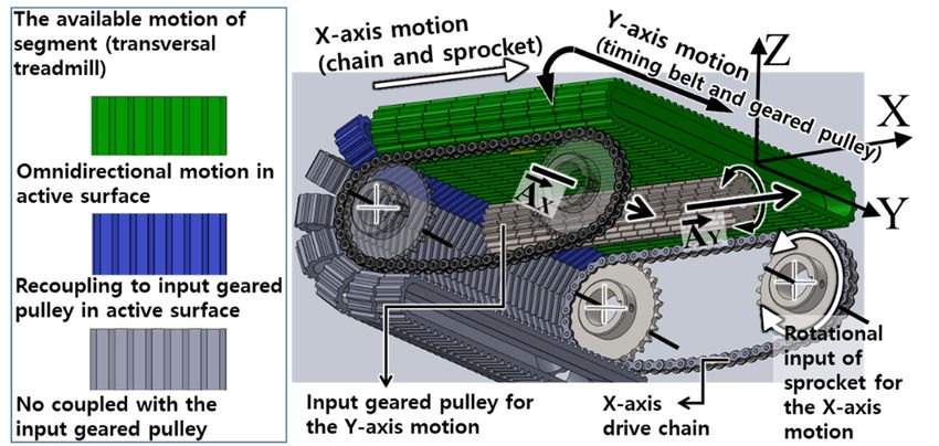
Appl. Sci. 2021, 11, 4223                                                                                            3 of 20

                            a special transmission system. This design, due to the light weight of the individual
                            segments, may improve the maximum speed and acceleration of the systems during X-axis
                            translational motion as compared to those of the Cyberwalk and Torus treadmill. To drive
                            each segment belt while allowing free movement in the X-axis direction, these ODTs use a
                            frictional transmission mechanism composed of omni-wheels. However, since the omni-
                            wheels-based frictional transmission mechanism has a low power transmission efficiency,
                            the maximum speed and acceleration of these ODTs for Y-axis translational motion are
                            limited. Thus, due to the high inertia of the unit segment treadmills for X-axis translational
                            motion and the low efficiency of power transmission for Y-axis translational motion, the
                            currently available 2D treadmills are only able to accommodate slow human walking
                            speeds and accelerations. This limitation is the main obstacle in developing an immersive
                            VR environment with fast and natural locomotion.
                                  A further complexity in the design of a past paced ODT is that even after improving
                            the power transmission efficiency for Y-axis motion and reducing the mass of moving
                            components for X-axis motion, the actuation scheme of the ODT must be carefully designed
                            to reduce structural stress in the ODT’s frame; additionally, the design should minimize
                            energy loss from the actuators to the power transfer components during motor actuation.
                                  In this study, we have developed a novel locomotion interface device, which is based
                            on an omnidirectional treadmill with a transmission mechanism that is referred to as the
                            geared omni-pulley (GOP). To overcome the limitations of conventional ODTs and to deal
                            with the complexities of fast ODT design, the proposed locomotion interface device has
                            the following capabilities: (1) X- and Y-axis translational motion generation through a
                            novel gear-based power transmission mechanism; (2) a distributed power scheme in which
                            two motors installed on each axis are synchronized using low-level synchronized motor
                            control [17]; and (3) high-level feedback using robust integral of the sign of the error (RISE)
                            control [18] to allow fast movements while changing the walking direction.
                                  The remainder of the paper is organized as follows; the main design concepts for the
                            locomotion interface device with high speed and acceleration are presented in Section 2,
                            the high-level controller design for the proposed locomotion interface and pilot study
                            results are in Sections 3 and 4. Finally, the conclusions drawn are given in Section 5.

                            2. LI Device Design for Fast Motion
                            2.1. Actuation of Unit Segment Belt by Geared Transmission
                                  For 2D treadmills, the main issue is how to actuate the segment belt for Y-axis motion.
                            In Torus and Cyberwalk treadmills, as shown in Figure 2a, each segment requires a ded-
                            icated actuator, which increases the segment mass due to the inclusion of the actuating
                            parts and thus makes it a disadvantageous design for implementing fast X-axis motion.
                                  In the US ARL ODT (United States Army Research Laboratory Omnidirectional
                            Treadmill), as shown in Figure 2b, a motor attached to the system frame can drive the
                            segment belt through an omni-wheel-based power transmission mechanism. The power
                            from the frame-fixed motor can be transmitted to the segment belt for Y-axis motion by
                            the omni-wheels, while the rollers of the omni-wheels that are in contact with the segment
                            belt passively rotate when the segments move along X-axis. This transmission is based
                            on line–contact friction, which limits the ability of the segment belt to follow the fast
                            movements of a user along Y-axis. To enhance the transmission efficiency of segment belt
                            actuation, we propose the novel gear transmission method shown in Figure 2c to directly
                            drive each segment belt [19]. Since the segment belts are driven by geared-pulleys, the
                            transmission efficiency is significantly enhanced as compared to the frictional transmission
                            by an omni-wheel. Moreover, the proposed concept is suitable to generate fast X-axis
                            motion due to a lightweight platform with low segment mass/inertia.
                                  The omnidirectional rack described in [20] may be considered a suitable mechanism for
                            orthogonal translation motion. However, it is not appropriate for creating infinite ground
                            because the rack gear is made using a rigid material, which is not flexible such as timing
                            belt. The proposed transmission mechanism for Y-axis translation can use commercially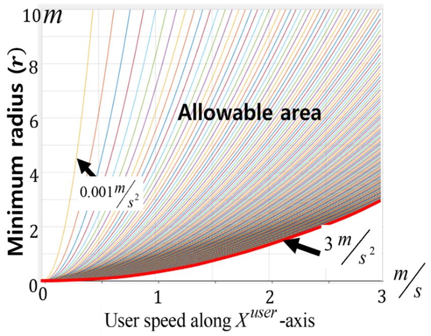
Appl. Sci. 2021, 11, x FOR PEER REVIEW 4 of 20
The omnidirectional rack described in [20] may be considered a suitable mechanism
Appl. Sci. 2021, 11, 4223 for orthogonal translation motion. However, it is not appropriate for creating infinite
4 of 20
ground because the rack gear is made using a rigid material, which is not flexible such as
timing belt. The proposed transmission mechanism for Y-axis translation can use com-
mercially available timing belts as segment belts (Standardized name: T10 Urethane belt,
available timing belts as segment belts (Standardized name: T10 Urethane belt, pitch
pitch specification: 10 mm).
specification: 10 mm).
2.2.
2.2.Transmission
TransmissionDesign
DesignforforOmnidirectional
OmnidirectionalMotion
Motion
Figures
Figures1 1and
and2c2cshow
showthetheconceptual
conceptualdesign
designofofthe
theproposed
proposed2D 2Dtranslational
translationalmotion
motion
with geared-pulley transmission. This simple holonomic design
with geared-pulley transmission. This simple holonomic design allows generationallows generation of infi-of
nite motion in both axes. In addition, this actuation method only drives
infinite motion in both axes. In addition, this actuation method only drives the segmentthe segment belts
that
beltsare onare
that theonactive surface
the active where
surface the user
where can can
the user locate andand
locate walk. This
walk. Thiscancanreduce
reducethe the
required
required motor power as less than half of the segment belts are actuated at any giventime.
motor power as less than half of the segment belts are actuated at any given time.
However,
However,when whenthe theproposed
proposedmechanism
mechanismcreates
creates2-dimensional
2-dimensionalground
groundby byactuating
actuatingbothboth
XXandandYYaxes,
axes,the
thecoupled
coupledsurfaces
surfacesofofthethegeared-pulleys
geared-pulleysand andsegment
segmentbelts
beltsget
getfrictional
frictional
forces
forcesbecause
becausethe segment
the segment belt should
belt should alsoalso
move
movein aindirection perpendicular
a direction perpendicular to the
todi-the
rection of the transmitted force of the input geared pulley. Thus, the geared
direction of the transmitted force of the input geared pulley. Thus, the geared pulley needs pulley needs
totobebemodified
modifiedtotoinclude
includea apassive
passiverotation
rotationmechanism
mechanismfor forreducing
reducingthis
thisfriction.
friction.InInthis
this
paper,
paper, we implement the Y-axis motion using a geared omni-pulley set (GOPS)equipped
we implement the Y-axis motion using a geared omni-pulley set (GOPS) equipped
with
withtoothed
toothedrollers
rollersinstead
insteadofofthe
theconventional
conventionalgeared
gearedpulley,
pulley,as
asshown
shownin inFigure
Figure3a.3a.
(a)
(b)
Figure
Figure3.3.(a)(a)GOPS
GOPSdesign
designincluding
includingtoothed
toothedrollers,
rollers,(b)
(b)The
Thefront
frontprojection
projectionofofGOPS
GOPSdesign
designwith
with a
a normal
normal geared-pulley
geared-pulley parameter,
parameter, and
and GOPS
GOPS configuration
configurationwith
withits
itsgeometric
geometricanalysis.
analysis.
The
Thedesign
designconcept
conceptofofGOPS
GOPSisisorganized
organizedbybyan
anomni-wheel
omni-wheelwith withgear.
gear.The
Thehigh
high
→
transmission
transmissionefficiency
efficiencyofofthe
thegear
gearisisused
usedfor
formotion
motionin the AA
inthe Y direction, while the friction
Y direction, while the friction
on the tooth surface caused by motion in the AX direction→ is reduced by the passive rota-
on the tooth surface caused by motion in the AX direction is reduced by the passive
tion of the toothed rollers, similar to an omni-wheel. The toothed roller for reducing the
rotation of the toothed rollers, similar to an omni-wheel. The toothed roller for reducing
frictional force is designed by body of rotation of an involute toothed part of a normal
the frictional force is designed by body of rotation of an involute toothed part of a normal
geared pulley along the rotational vector → shown in Figure 3b. This rotational vector
geared pulley along the rotational vector N shown in Figure 3b. This rotational vector also
represents the axis of the passive rotation of the toothed rollers when segments move along
the X-axis.
In the presented system, the design of the GOPS uses the specifications of the com-
mercial product called the T10 type geared pulley that works with the T10 Urethane belt.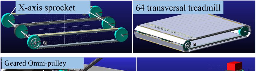
Appl. Sci. 2021, 11, x FOR PEER REVIEW 5 of 20
also represents the axis of the passive rotation of the toothed rollers when segments move
Appl. Sci. 2021, 11, 4223 5 of 20
along the X-axis.
In the presented system, the design of the GOPS uses the specifications of the com-
mercial product called the T10 type geared pulley that works with the T10 Urethane belt.
The
The parameters
parameters of of the
thenormal
normalgeared
gearedpulley,
pulley, which
which areare independent
independent of number
of the the number of
of teeth,
teeth, pitch (p = 10 mm), tooth height (t = 3.2 mm), tooth width (w
pitch (p = 10 mm), tooth height (th = 3.2 mm), tooth width (wh = 2.76 mm) and input angle
h h = 2.76 mm) and input
angle
of theoftooth
the tooth
(λ = 25 (λdeg).
= 25 deg). Moreover,
Moreover, GOPSGOPS designdesign also considers
also considers the parameters
the parameters de-
depended
pended on the number
on the number of teethof(Z teeth
= 36)(Zsuch
= 36)as such as radius
radius of theof the pitch
pitch circle circle (rp = 57.295
(rp = 57.295 mm),mm),
total
total radius
radius (r =(r56.375
= 56.375 mm)mm) of of
thethe GOPS
GOPS andand theradius
the radiusofofthethebase
basecircle
circle (r
(rbb == 53.175
53.175mm)mm)
because the frontal projection of the GOPS is identical to a normal geared-pulley
because the frontal projection of the GOPS is identical to a normal geared-pulley profile. profile.
Among
Amongthe theGOPS
GOPSconfiguration
configurationparameters
parametersshown shownininFigure
Figure3b, 3b,the
thenumber,
number,n, n,ofof
toothed
toothedrollers
rollersisisthe
themain
maindeterminant.
determinant.Figure Figure44shows
showsthe theexample
exampleofofhow howto toproperly
properly
setup
setupthetheGOPS
GOPSconfiguration
configuration in in
thethe
case thatthat
case the the
number
number of toothed rollers
of toothed is 6. The
rollers is 6.rela-
The
tionship between
relationship the total
between number
the total of teeth
number (Z) and
of teeth (Z) the
andnumber
the numberof toothed rollers
of toothed (n) de-
rollers (n)
defines
fines to the
to the module
module of the
of the GOPSGOPS(mGOP(m)GOP ) as follows:
as follows:
mGOP Z / n(n (=n =2a2a≥≥6,6,aa≥≥ 33)),, ((a,a,Z,
mGOP==Z/n Z ,n,
n, m GOP ∈
mGOP ),,
∈ N) (1)
(1)
where
wherea∈ℕa∈N isis aa positive
positive natural
natural number
number greater than or
greater than or equal
equal toto 3.
3. Thus,
Thus, mmGOP
GOP represents
represents
the
the number of teeth in one toothed roller. It can also define an appropriatenumber
number of teeth in one toothed roller. It can also define an appropriate numberfor fornn
because
becausethe
thenumber
numberofofteeth
teethmust
mustbe beaanatural
naturalnumber.
number.All Alltoothed
toothedrollers
rollershave
haveananindex
index
number
number(i(ith) according
th ) according to the
to range
the range 1 ≤1 i∈≤ℕ ≤
i n,
∈N as
≤ shown
n, as in
shownFigure
in 4. Odd
Figure 4. and
Oddeven
andnum-
even
bers in thein
numbers toothed roller roller
the toothed indexindex
(i) make up each
(i) make up separate geared
each separate omni-pulley
geared (GOP)(GOP)
omni-pulley (see
also
(seeFigure 3), and
also Figure 3),two
andGOPs are combined
two GOPs are combined to form one GOPS.
to form one GOPS.
.
GOPSdesign
Figure4.4.GOPS
Figure designparameters
parametersand
andrange
rangeofoftoothed
toothedroller
rollersize.
size.
InInthe
thedesign
designofofGOPS,
GOPS,the thetotal
totalnumber
numberofofteeth teeth(Z)(Z)ofofthe
theGOPS
GOPSisis 36,36, andanditsits 66
toothed rollers are configured with a uniform angular spacing of 60 ◦ . To configure the
toothed rollers are configured with a uniform angular spacing of 60°. To configure the
frontalprojection
frontal projectionofofthis
thisGOPS
GOPSaccording
according toto the
the normal
normal geared-pulley
geared-pulley profile,
profile, oneone GOP
GOP is
is placed behind the other with a phase offset of 60 ◦ between the toothed rollers of both
placed behind the other with a phase offset of 60° between the toothed rollers of both the
the GOPs.
GOPs.
Oncethe
Once theGOP
GOParrangement
arrangementisisset, set, the
the next
next stepstep is
is selecting
selecting the
the size of rrroller
size of asthe
rolleras the
GOPS design parameter, whose range is calculated by the general geared-pulley parameters
GOPS design parameter, whose range is calculated by the general geared-pulley parame-
(p, th , etc.) and the GOPS configuration parameter (n) that has already been determined.
ters (p, th, etc.) and the GOPS configuration parameter (n) that has already been deter-
Due to the shape of the toothed roller, the radius at its end (r ) is used to define its size.
mined. Due to the shape of the toothed roller, the radius at itsroller end (rroller) is used to define
Moreover, rroller_thick is defined as the largest radius at the center of the toothed roller, as
its size. Moreover, rroller_thick is defined as the largest radius at the center of the toothed roller,
shown in the right-side image of Figure 4. r has the following range:
as shown in the right-side image of Figure 4.roller rroller has the following range:
th r
< rroller < . (2)
sin π 1.5n−1
+ p/4r p 4 sin(2π/n)
n
Thus, the minimum rroller is calculated to maintain the proper tooth shape, and its
maximum size corresponds to the circumcenter point to avoid interference between the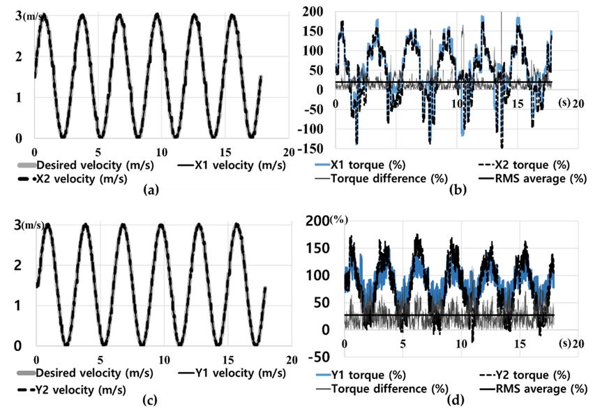
th r
< rroller < .
Appl. Sci. 2021, 11, 4223
(
sin π 1.5nn−1 + p / 4rp ) 4sin ( 2π / n) (2)
6 of 20
Thus, the minimum rroller is calculated to maintain the proper tooth shape, and its
maximum size corresponds to the circumcenter point to avoid interference between the
arrangements of each toothed roller installed in a GOP. The selected rroller defines the value
arrangements of each toothed roller installed in a GOP. The selected rroller defines the value
of rroller_thick according to the following relationship:
of rroller_thick according to the following relationship:
( (
rroller _ thick==rrroller ++r(r−−r sin
rroller_thick roller
π 1.5n −1 / n . ))
|r sin((π (1.5n )− 1)/n)|). (3)(3)
In In
thethe
presented
presented design, the
design, value
the ofof
value rroller is 10.82
rroller mm,
is 10.82 mm,which
whichis selected considering
is selected considering
thethe
range of rroller calculated using Equation (2) (3.6~16.27 mm), and do is selected as 28.5
range of rroller calculated using Equation (2) (3.6~16.27 mm), and do is selected as
mm to mm
28.5 avoidtointerference between
avoid interference the toothed
between rollers rollers
the toothed of the GOPs.
of the GOPs.
2.3.2.3.
Realization of Stable
Realization Omnidirectional
of Stable Motion
Omnidirectional Motion
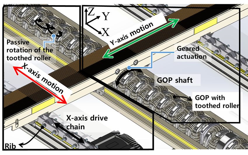
Figure
Figure5a5ashows
shows howhow thethe
ODT
ODT can generate
can generate X-axis
X-axismotion
motion through
through segment
segment rotation
rotation
→
along
alongA Adefined in Figure 1. The segments are pin-constrained to the rib of the X-axis
X defined in Figure 1. The segments are pin-constrained to the rib of the X-
drive chain. As compared
axis drive chain. As compared to a timing to belt mechanism
a timing [19], the chain
belt mechanism [19],mechanism improves
the chain mechanism
theimproves
transmission efficiency of X-axis drive by allowing the precise positioning
the transmission efficiency of X-axis drive by allowing the precise positioning of each seg-
ment without collisions between segments at high speeds. In the unit
of each segment without collisions between segments at high speeds. In the unit segment segment (transverse
treadmill) design
(transverse with a timing
treadmill) design belt
withdriven
a timingusing
beltGOPS,
driventhe segment
using GOPS, belt
thehas been turned
segment belt has
inside
beenout so that
turned the toothed
inside side the
out so that of the belt is side
toothed coupled
of thewith the
belt is teeth of the
coupled GOPS,
with while of
the teeth
a belt tensioner
the GOPS, retains
while a beltthe segmentretains
tensioner belt tension. A frame-fixed
the segment motor(s)
belt tension. drives the
A frame-fixed seg-
motor(s)
ment timing
drives belt continuously
the segment timing belt through the GOPS
continuously to achieve
through Y-axistomotion,
the GOPS achievewhile
Y-axisallow-
motion,
ingwhile
translational
allowingmotion of segments
translational motion along the X-axisalong
of segments throughthe the passive
X-axis rotation
through the of the
passive
toothed rollers [19,21]. It should be noted that the number of contact teeth
rotation of the toothed rollers [19,21]. It should be noted that the number of contact teeth between one
segment
between belt
oneand one GOPS
segment belt is setone
and to be the same
GOPS is set as
to mbeGOP . same as mGOP .
the
(a)
Figure 5. Cont.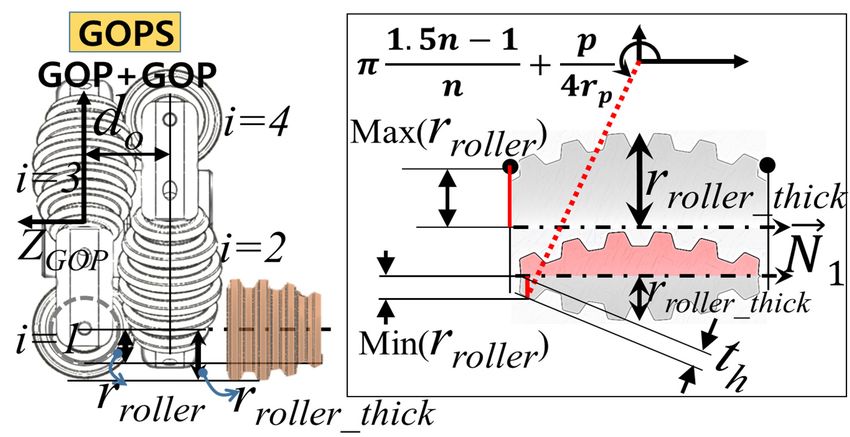
Appl. Sci. 2021, 11, 4223 7 of 20
Appl. Sci. 2021, 11, x FOR PEER REVIEW 7 of 20
Appl. Sci. 2021, 11, x FOR PEER REVIEW 7 of 20
(b)
(b)
Figure 5.
Figure 5. (a) Drive chain of segment
segment treadmills
treadmills for
for X-axis
X-axismotion,
motion,(b)
(b)Design
Designand
andoperation
operationofofthe
the
Figure 5. (a) Drive
synchronizer chain of segment treadmills for X-axis motion, (b) Design and operation of the
mechanism.
synchronizer mechanism.
synchronizer mechanism.
When
Whenaasegment
segmentbelt beltenters
entersthetheactive
activesurface,
surface, asasshown
shown in in
Figure
Figure5b 5b
(See alsoalso
(See Figure 1),
Figure
When aspeed
a1),rotational segment belt enters
mismatch occurs thebetween
active surface,
the the as shown
segment beltin Figure 5b
entering the(See alsosurface
active Figure
a rotational speed mismatch occurs between segment belt entering the active sur-
1), a rotational
without GOPS speed mismatch
coupling and the occurs between the segment belt entering the Therefore,
active sur-
face without GOPS coupling andsegment
the segment beltsbelts
already in the
already inactive surface.
the active surface. There-
face
speed without GOPS
synchronization coupling
should and the segment
be considered belts
to prevent already
damage in the active
to the to surface.
teeth, and toandThere-
guar-
fore, speed synchronization should be considered to prevent damage the teeth, to
fore,
antee speed
smooth synchronization
gear coupling should
during be considered
the re-coupling to prevent
stage.stage. damage to the teeth, and to
guarantee smooth gear coupling during the re-coupling
guarantee
For smooth gear coupling during the re-coupling stage.
For the
the proposed
proposed F-ODT,F-ODT, aa speed
speedsynchronizer
synchronizer is is used
used totoaccelerate
accelerate thethere-coupling
re-coupling
segment For the proposed F-ODT, a speed synchronizer isAs used to accelerate the re-coupling
segment beltbelt in in advance
advance through
through frictional
frictional actuation.
actuation. As aa unit unit segment
segment approaches
approaches the the
segment
edge of belt
the in advance
GOPS, a cone through
shaped frictional actuation.
synchronizer increases As its
a unit
belt segment
speed to approaches
match that the
of
edge of the GOPS, a cone shaped synchronizer increases its belt speed to match that of the
edge
the of
belts the GOPS,
already a cone
coupled shaped
with synchronizer
the GOPS. increases
Thus, the its belt
synchronizer speed to match
minimizes that
the of the
speed
belts already coupled with the GOPS. Thus, the synchronizer minimizes the speed mis-
belts already
mismatch betweencoupled with the GOPS. Thus, therecoupled.
synchronizer minimizes the speed mis-
match between the the
GOPS GOPSandandthethe
beltbelt
beingbeing
recoupled.
match between the GOPS and the belt being recoupled.
2.4.
2.4. Design
Design of of Actuation
Actuation System
System forfor Desired
DesiredPerformance
Performance
2.4. Design
When a human try to run orDesired
of Actuation System for Performance
stop quickly during straight walking, a maximum
When a human try 2 to run or stop quickly during straight walking, a maximum accel-
acceleration
When aof 32 m/stryistogenerated
human run or stop[22]. Thus,
quickly the target
during straightperformance of velocityaccel-
walking, a maximum and
eration of 3 m/s is generated [22]. Thus, the target performance 2 , respectively, of velocity and accelera-
acceleration
eration of 3 m/s of the
2 isODT were set
generated [22].toThus,
3 m/sthe and 3
targetm/s performance of to simulate
velocity and running
accelera-
tion of the ODT were set to 3 m/s and 3 m/s2, respectively, to simulate running and stop-
and
tionstopping.
of the ODT To were
validate the3target
set to m/s and performance, dynamic analysis
3 m/s2, respectively, to simulate wasrunning
performed andusing
stop-
ping. To validate the target performance, dynamic analysis was performed using a com-
aping.
commercial multibody dynamics software (ADAMS), as shown
To validate the target performance, dynamic analysis was performed using a com- in Figure 6. To obtain
mercial multibody dynamics software (ADAMS), as shown in Figure 6. To obtain realistic
realistic analysis results,
mercial multibody dynamicsthe boundary conditions,asincluding
software (ADAMS), shown inthe mass
Figure 6. and inertia,
To obtain were
realistic
analysis results, the boundary conditions, including the mass and inertia, were set based on
set basedresults,
analysis on 3D modeling,
the boundary gravity, the initial
conditions, X-axisthe
including drivemasschain
andtension
inertia, (3000
were setN) based
and the on
3D modeling, gravity, the initial X-axis drive chain tension (3000 N) and the Coulomb fric-
Coulomb
3D modeling, friction due to
gravity, contact
the initial between
X-axis drivethe segment
chain tension belt and
(3000 theN)Teflon-coated
and the Coulomb segmentfric-
tion due to contact between the segment belt and the Teflon-coated segment structure [19].
structure
tion due to [19].
contact between the segment belt and the Teflon-coated segment structure [19].
Figure 6. Dynamics simulation for X and Y axes.
Figure6.6.Dynamics
Figure Dynamicssimulation
simulationfor
forXXand
andYYaxes.
axes.
The X-axis motion simulation was done by actuating all 64 unit segments (total
TheX-axis
The X-axis motion simulation
waswas done by actuating all 64 unit segments (total
weight: 576 kg)motion simulation
and human mass (150 done by actuating
kg) through all 64 unit
the rotation segments
of the (totalsprocket,
chain and weight:
weight:
576 576 kg) and mass
human mass (150 kg) through the rotation of the chain and sprocket,
and Y-axis motion was performed with one segment among the 27 segment belts onand
kg) and human (150 kg) through the rotation of the chain and sprocket, the
and Y-axis
Y-axis motionmotion was performed
was performed with
with one one segment
segment amongamong
the 27 the 27 segment
segment belts onbelts on the
the active
active surface loaded with 150 kg to simulate a human mass. The additional information
surface loadedloaded
active surface with 150 kg150
with to simulate a human
kg to simulate mass.mass.
a human The The
additional information
additional informationof
of the proposed ODT is summarized in Table 1, which is used to determine the actuator
of the proposed ODT is summarized in Table 1, which is used to determine the actuator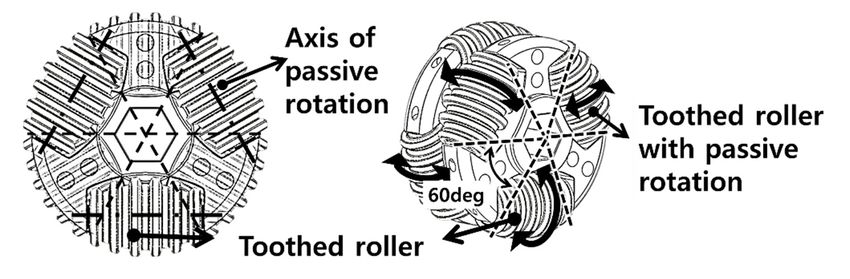
Appl. Sci. 2021, 11, 4223                                                                                                 8 of 20

                            the proposed ODT is summarized in Table 1, which is used to determine the actuator
                            power. The X-axis and Y-axis motor instantaneous powers required to maintain a speed of
                            3 m/s were determined to be 28 kW and 8 kW, with average values of 8.8 kW and 4.2 kW,
                            respectively. Table 2 summarizes the power requirements for each axis actuation.

                            Table 1. The ODT Specifications for Dynamic Simulation.

                                             Item                                        Specifications
                                 System frame dimensions                        2780 mm × 3310 mm × 640 mm
                                    Active surface area                                 2.5 m × 2.5 m
                                 Unit segment dimensions                        100 mm × 2577 mm × 70.5 mm
                                   Unit segment weight                                        9 kg
                                   Number of segments                                       64 units
                                 Number of active segments                                  27 units
                               Number of GOPS in 1 GOP shaft                       54 units per 1 GOP shaft
                                    Chain and timing belt                X-axis drive chain         Y-axis segment belt
                                             Pitch                          18.875 mm                     10 mm
                                            Width                             9.4 mm                      96 mm
                                  Actuation part specification               Sprocket                   GOP shaft
                                        Pitch diameter                      396.375 mm                  114.59 mm
                                     The number of teeth                         21                          36

                            Table 2. Power Requirements.

                                                                                Required Pulley
                                  Axis          Required Pulley Torque                                        Power
                                                                                Angular Velocity
                                                     1768 Nm (max.)                                        28 kW (peak)
                                   X                                               15.63 rad/s
                                                      563 Nm (avg.)                                       8.8 kW (nominal)
                                                     148.5 Nm (max.)                                        8 kW (peak)
                                   Y                                               52.35 rad/s
                                                      81 Nm (avg.)                                        4.2 kW (nominal)

                                 In the presented system, 3-rows of GOP shafts were installed to connect 6 GOPS per
                            one segment, as shown in Figure 7a, to secure the performance of the geared-coupling
                            between the segment and GOPS. Thus, this mechanism reduces the power concentration
                            on the contacted teeth of a segment belt by increasing the number of the contacted teeth
                            by 3 times. Therefore, it can guarantee the power transmission performance because the
                            generated motor torque required to drive the segment belt is distributed over the 3-row
                            GOP shaft. The motors (Motor1y , Motor2y ) actuate the power transmission belts, which
                            in turn drive the gearboxes. The gearboxes actuate timing belts for rotation of the 3 GOP
                            shafts simultaneously as a mechanically coupled power transmission system. The actuation
                            mechanism for the X-axis also uses a distributed power design, in which the four drive
                            chains are mechanically coupled. In Figure 7b, Motor1x and Motor2x simultaneously
                            actuate the drive chains by actuating the sprockets.
Appl. Sci. 2021, 11, 4223 9 of 20
Appl. Sci. 2021, 11, x FOR PEER REVIEW 9 of 20
(a)
(b)
Figure7.7. Mechanically
Figure Mechanicallycoupled
coupledactuation
actuationsystem
systemdesign:
design:power
powertransmission
transmissionmechanisms
mechanismsofof(a)(a)the
the Y-axis and (b) the X-axis.
Y-axis and (b) the X-axis.
As the
As thedesigned
designedODTODTrequires
requires(1) (1)aapower
powertransmission
transmissionmechanism
mechanismfor fordriving
drivingthethe
3-row GOP
3-row GOP shafts
shaftssimultaneously,
simultaneously,(2) (2)aachain-sprocket
chain-sprocketmechanism
mechanismfor forconstraining
constrainingand and
carryingthe
carrying thesegments,
segments,and and(3)
(3)aa frame
frame stiffness
stiffnesssuitable
suitableforfor high
high velocity
velocity and
and acceleration,
acceleration,
the
theinterior
interiorofofthe
theODT
ODT has very
has limited
very limitedspace. Therefore,
space. motion
Therefore, actuation
motion alongalong
actuation each axis
each
isaxis
generated using using
is generated two synchronized
two synchronized motors, as shown
motors, in Figure
as shown in 7. Under
Figure 7. this
Underdistributed
this dis-
actuation, the motors’
tributed actuation, thepower
motors’ can be distributed
power uniformly
can be distributed to all thetopower
uniformly all thetransmission
power trans-
components
mission components without excessive stress. Moreover, this actuation designcompara-
without excessive stress. Moreover, this actuation design provides provides
tively faster command
comparatively response than
faster command responsea single
thanmotor
a singledesign
motor[23].
design [23].
Since
Since the
the system uses
uses aa distributed
distributedpower powerscheme,
scheme,ititisisimportant
important to to achieve
achieve pre-
precise
cise
speedspeed control
control of both
of both actuators
actuators to prevent
to prevent damagedamage
to the to the power
power transmission
transmission com-
components
ponents [17]. To simultaneously
[17]. To simultaneously minimizeminimize the differences
the differences in speed andin speed
torqueand torque
of both of botha
actuators,
actuators, a cross-couple control scheme [24] was incorporated into the
cross-couple control scheme [24] was incorporated into the low-level control of the pro- low-level control of
the proposed ODT, as shown
posed ODT, as shown in Figure 8. in Figure 8.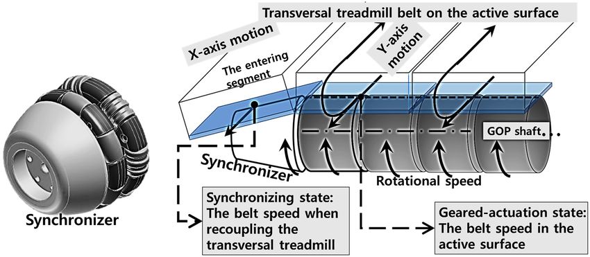
mission components without excessive stress. Moreover, this actuation design provides
comparatively faster command response than a single motor design [23].
Since the system uses a distributed power scheme, it is important to achieve precise
speed control of both actuators to prevent damage to the power transmission components
Appl. Sci. 2021, 11, 4223 [17]. To simultaneously minimize the differences in speed and torque of both actuators,
10 of 20a
cross-couple control scheme [24] was incorporated into the low-level control of the pro-
posed ODT, as shown in Figure 8.
Appl. Sci. 2021, 11, x FOR PEER REVIEW 10 of 20
Figure 8. Low-level speed controller for motor synchronization.
Figure 8. Low-level speed controller for motor synchronization.
Thelow-level
The low-levelcontroller
controller synchronizes
synchronizes the the motor
motor speeds
speeds according
according to the to the desired
desired speed
speed command i (vci), where vcx= [vycx,Tvcy]T is the desired speed of the active surface, and vi 1i
command (vc ), where vc = [vc , vc ] is the desired speed of the active surface, and v1
andvv2i i correspond
and correspond to to the
thevelocity
velocityof ofeach eachmotor,
motor,determined
determinedvia viaencoder
encoderfeedback
feedbackwith
with
2
respecttotothe
respect theXXororY-axis,
Y-axis,Tc1 i andTTc2c2i are
Tc1i and i are the
the torque
torque values.
values. Synchronization
Synchronizationfor forreducing
reducing
the difference of each motor’s speed (vvi) and torque (vTi i) in each axis was achieved by
i
the difference of each motor’s speed (vv ) and torque (vT ) in each axis was achieved by
proportional-derivative(PD)
proportional-derivative (PD)control,
control,asasfollow:
follow:
d (v −− v2i v) i i
vv = Cv v = C ( v , v ) = k ( v − v )+
i i i i i i i i 1 1i
i id v
+k 2, i = X , Y ,
i i
vv 1 i , v2v i 1= k
2 Pv vPv1 i −1 v2 i2
, i = X, Y, kDv (4)
(4)
Dv
dt dt
wherekPv
where kPvand
andkkDv Dv are the positive gains of the speed
speed controller.
controller.The
Thetorque
torquesynchronization
synchronization
controllerisisalso
controller alsoimplemented
implementedusing
usingPD
PDcontrol,
control,asasfollows:
follows:
ddTcT1i c1−iT− (
i
c 2 Tc2
i
)
( ) ( )
ii iii i i ii i ii
i
v T = Ct i
Tvc1T ,=TCc2t Tc1=,Tkc2Pt = kTPtc1 T−
c1 T−c2Tc2 +
+ kkDtDt , i = X, ,Y
i=, X, Y, (5)
(5)
dt dt
wherekPt
where kPti i and
andkkDtDti are the positive
positive gains
gains of ofthe
thetorque
torquesynchronization
synchronizationcontroller,
controller,andandTc1 i i
Tc1
and
and Tc2 Tc2i are the torque values for the control input of C i
i. To secure control
the torque values for the control input of Ct . To secure control stability of
t stability of the
low-level
the low-level controller, suitable
controller, suitablegains were
gains selected
were based
selected on the
based Nyquist
on the Nyquist criterion by con-
criterion by
sidering thethe
considering backlash
backlash model
model[19,25].
[19,25].InInterms
termsof of the criterion, the
the Nyquist criterion, theintersection
intersection
showsaamarginally
shows marginallystable stablecondition,
condition, i.e.,
i.e., within
within 0.40.4
Hz.Hz. Regarding
Regarding thethe
gaingain of the
of the control-
controller,
i = 0.1i and 0.5, k i = 0.02
kPvas; i = 0.2i and 0.4, and
the
ler,Xthe
andXYand values were set
Y values wereas;set kPv = 0.1 andDv 0.5, kDvi =and and k0.04,
0.020.04, Pt kPt = 0.2 and 0.4,
kandi = 0.08 and 0.1, respectively.
Dt kDt = 0.08 and 0.1, respectively.
i
2.5.
2.5.Fabricating
FabricatingthetheODT
ODTandandVerifying
VerifyingthethePerformance
Performance
The proposed ODT fabricated as
The proposed ODT fabricated as shown shown inin
Figure 9 has
Figure thethe
9 has following major
following character-
major charac-
istics: (1) high transmission efficiency via the novel GOPS for driving the segment
teristics: (1) high transmission efficiency via the novel GOPS for driving the segment beltsbelts
for
Y-axis motion, (2) low-weight unit segments for fast X-axis motion, (3) distributed
for Y-axis motion, (2) low-weight unit segments for fast X-axis motion, (3) distributed mo- motor
actuation to reduce
tor actuation the motion
to reduce response
the motion timetime
response and the
andstrain on transmission
the strain parts.parts.
on transmission
Figure9.9.The
Figure Thedeveloped
developedODT
ODTusing
usingGOP
GOPactuation
actuationon
onthe
theactive
activesurface,
surface,distributed
distributedactuation,
actuation,
and
and the dynamics simulations results.
the dynamics simulations results.
To verify the performance of the proposed ODT, we measured the maximum accel-
eration and velocity of the active surface. The motion command was given as a sinusoidal
signal of a magnitude of 3 m/s at 0.16 Hz for generating the maximum acceleration of 3
m/s2. In addition, to verify the low-level controller, the velocity and torque transmitted
from the motors were also measured.Appl. Sci. 2021, 11, 4223 11 of 20
To verify the performance of the proposed ODT, we measured the maximum accelera-
tion and velocity of the active surface. The motion command was given as a sinusoidal
signal of a magnitude of 3 m/s at 0.16 Hz for generating the maximum acceleration of
3 m/s2 . In addition, to verify the low-level controller, the velocity and torque transmitted
from the motors were also measured.
Figure 10 shows the results of the maximum speed and acceleration. The root mean
square (RMS) value of the speed difference was 0.0087 m/s for the Y-axis, and 0.0013 m/s
Appl. Sci. 2021, 11, x FOR PEER REVIEW 11 of 20
for the X-axis, respectively, as shown in Figure 10a,c. Thus, the speed synchronization
and command-following performance are considered to be stable. In the Y-axis case, the
RMS value of the torque bias was 27%, while in the X-axis case, the RMS value of torque
was
bias20%,
was as shown
20%, FigureFigure
as shown 10b,d. 10b,d.
Thus, the low-level
Thus, controller
the low-level can overcome
controller the nonlin-
can overcome the
earities presentpresent
nonlinearities in the in
power transfer
the power process
transfer and adequately
process distribute
and adequately the load
distribute to the
the load to
the motors
motors while
while executing
executing the motion
the motion commands.
commands. It also
It can can also adequately
adequately compensate
compensate for
for the
the torque
torque difference.
difference.
Figure10.
Figure Verification of
10.Verification of the
the performance
performance using
using aa sinusoidal
sinusoidal motion
motion command
command for
for surface
surface acceler-
accelera-
tion of 3 m/s 2 . (a) Y-axis speed synchronous performance, (b) Y-axis torque synchronous performance,
ation of 3 m/s . (a) Y-axis speed synchronous performance, (b) Y-axis torque synchronous perfor-
2
(c) X-axis
mance, (c) speed
X-axissynchronous performance,
speed synchronous and (d)and
performance, X-axis
(d)torque
X-axis synchronous performance.
torque synchronous perfor-
mance.
In the maximum performance, both axes showed a torque requirement of about
1.75 In
times
the the rated motor
maximum capacity, due
performance, bothtoaxes
the showed
implicit friction
a torqueofrequirement
the real system. However,
of about 1.75
the servo motors guarantee operation at 200% of the rated torque capacity
times the rated motor capacity, due to the implicit friction of the real system. However, for a period
of 5~10-min.
the servo motors Therefore,
guaranteetheoperation
system can safelyofachieve
at 200% the ratedhigh velocities
torque andfor
capacity accelerations
a period of
exceeding 3 m/s and 3 m/s 2 , respectively.
5~10-min. Therefore, the system can safely achieve high velocities and accelerations ex-
ceedingTable 3 compares
3 m/s and 3 m/sthe specifications of the existing 2D treadmills and the proposed
2, respectively.
ODT. The proposed ODT has a workspace
Table 3 compares the specifications of 2.5
of the m × 2.5
existing 2Dm, which isand
treadmills sufficient for safe
the proposed
running and various other types of locomotion, such as crawling.
ODT. The proposed ODT has a workspace of 2.5 m × 2.5 m, which is sufficient for It can achieve the higher
safe
velocities and accelerations than the others. Also, due to the use of the distributed
running and various other types of locomotion, such as crawling. It can achieve the higher actuation
system, the
velocities and overall system height
accelerations than theisAppl. Sci. 2021, 11, 4223 12 of 20
Table 3. Comparison with Existing 2D Treadmills.
Y-axis Drive Active Surface Max. vel. Max. acc.
Actuator Specification
Mechanism Area/Thickness (km/h) (m/s2 )
Frame stationery motor 1.3 × 1.3 m2 X-axis 4 kW (1 EA)
US army ODT 1 7.2 Under 1
with omni-wheel /0.46 m Y-axis 4 kW (1 EA)
Segment attached 6.5 × 6.5 m2 X-axis 40 kW (4 EA) 7.2 0.5
Cyber Walk
motor /1.5 m Y-axis 37.5 kW (25 EA) 10.8 0.75
Segment attached 1 × 1 m2 X-axis 200 W (1 EA) 4.3 1
Torus treadmill
motor /0.5 m Y-axis 960 W (12 EA) 4.3 0.8
Frame stationery motor 2.5 × 2.5 m2 X-axis 8.8 kW (2 EA) 10.9 3
Proposed ODT
Appl. Sci. 2021, 11, x FOR PEER GOPS 2
withREVIEW /0.64 m Y-axis 5.8 kW (2 EA) 10.9 3 12 of 20
ODT 1 : omnidirectional treadmill, GOPS 2 : geared omni-pulley set.
3. LI
3. LI Control
Control for
for Omnidirectional
OmnidirectionalRunning
Running
3.1.
3.1. Design
Design of
of High-Level
High-Level Controller
Controller
For
Foreffective
effectivetreadmill-based
treadmill-basedgait gaitexercise,
exercise,aauser
userspeed
speedadaptation
adaptationcontroller
controllershould
should
converge
converge toto an
an intentional
intentional speed
speed of
of aauser
userfast
fastand
andprecisely
precisely[26].
[26]. Moreover,
Moreover, ititshould
should
effectively
effectivelycompensate
compensatethe theposition
positionerror
error from
from the reference
the referenceposition to prevent
position to prevent feetfeet
twisting
twist-
within turning
ing within motions
turning in 2Din
motions treadmill simulations
2D treadmill [15]. This
simulations [15].isThis
because if a userifperforms
is because a user per- a
step turning while too away from the reference position, an excessively
forms a step turning while too away from the reference position, an excessively unin- unintended motion
of the active
tended motionsurface
of the inactive
ODT occurs
surfaceininlateral direction.
ODT occurs in lateral direction.
To verify that the fast directional changes
To verify that the fast directional changes duringduring walking and running
walking and runningis possible using
is possible
to the proposed
using ODT byODT
to the proposed conducting turn walking,
by conducting the high-level
turn walking, controller
the high-level facilitating
controller is
facili-
designed by using the
tating is designed by 1D treadmill
using the 1Dsystem
treadmillmodel shown
system in Figure
model shown 11.inWhen
Figurewalking
11. Whenor
running,
walking the position the
or running, error is derived
position errorasisfollows
derived[27]:
as follows [27]:
.
d( x d−( xd−)/dt
xd ) /=dt−=v−cv+ vww, ,vcv=
c +v c =a
ac ,c , (6)
(6)
wherexxisisthe
where thecurrent
currentuser userposition
positionwith
withrespect
respecttotothe thereference position,xxd disisthe
referenceposition, thedesired
desired
position, v is the intentional velocity of the
position, vww the intentional velocity of the user, and vc anduser, and v c and a c the treadmill beltbelt
ac areare the treadmill ve-
velocity
locity and and acceleration
acceleration commands,
commands, respectively.
respectively. In the
In the modelmodel
shownshown in Equation
in Equation (6), v(6),
c is
vapplied
c is applied to treadmill
to the the treadmillservoservo motors,
motors, where where its dynamics
its dynamics are compensated
are compensated by thebylow-
the
low-level controller.
level controller. To avoid
To avoid sudden
sudden variations
variations in belt
in belt acceleration,
acceleration, the the dynamics
dynamics areareex-
extended using a . The final control input (v ) can be obtained by time-domain
tended using ac. The final control input (vc) can be obtained by time-domain integration of
c c integration
ac.aTo
of c . To maintain
maintain thethe user
user at the
at the center
center position,
position, the the desired
desired position
position (xd) (x ) is to
isdset setzero
to zero
(i.e.,
(i.e., x = 0) and saturation is applied to
xd = 0)d and saturation is applied to vc to remove vc to remove
the oscillatory command due to thetonega-
the oscillatory command due the
negative position error when a user does not
tive position error when a user does not intend to walk. intend to walk.
Figure11.
Figure 11.High-level
High-levelLI
LIcontroller
controllerfor
foraa1D
1Dtreadmill.
treadmill.
As shown
As shown in Figure 12, for
for expanding
expandingto tothe
the2D
2Dtreadmill
treadmillmodel,
model,the user
the should
user should be
able
be ableto maintain
to maintainforward locomotion
forward locomotionwhile changing
while the the
changing walking direction.
walking Thus,
direction. the con-
Thus, the
controller uses user
troller uses thethe measured
measured userorientation
user orientationangle
angle(θ)
(θ) to
to create the
the user
usercoordinates
coordinates(X(X user,,
Y ). The X -axis is set up along the anterior-posterior (AP) direction of the user’s body,
user user
and the Yuser-axis is along the medio-lateral (ML) direction. The walking intention ( ),
referred to in treadmill coordinates, is converted to in the user coordinates. To in-
terface with the walking intention , the control command =
[ , ,
] is generated by the high-level controller with respect to the user coor-Appl. Sci. 2021, 11, 4223 13 of 20
Yuser ). The Xuser -axis is set up along the anterior-posterior (AP) direction of the user’s body,
and the Yuser -axis is along the medio-lateral (ML) direction. The walking intention (vw ),
referred to in treadmill coordinates, is converted to vuser
w in the user coordinates. To interface
h iT
X, user
with the walking intention vuser w , the control command vc
user =
vc vY,user
c is
generated by the high-level controller with respect to the user coordinates. Then, this
control command is transformed into treadmill coordinates as vc . According to the adaptive
treadmill controller, which can be considered to be a cascade system [28], the linear growth
rate of the interconnection term and the convergence property represented by Equation (6)
guarantee the stability of the entire system. Thus, the control command (vc ) for interfacing
Appl. Sci. 2021, 11, x FOR PEER REVIEW
with the 2D gait information is derived as follows: 13 of 20
vc =Rz,θ vuser
c = Rz,θ (v̂user
w +µ
user
), (7)
where , is the orientation matrix of the Z-axis according to the orientation of the user,
where Rz,θ is the orientation matrix of the Z-axis according to the orientation of the user,
is a continuous input using the RISE controller [29] to compensate for the user po-
µuser is a continuous input using the RISE controller [29] to compensate for the user position
sition error due to error in the estimation of user , and is the 2D feed-forward term
error due to error in the estimation of vw , and v̂w is the 2D feed-forward term based on
based on the user’s coordinates, which is simply expanded from [27], as follows:
the user’s coordinates, which is simply expanded from [27], as follows:
w = ko ( p
vˆ user -ξ ) ., ξ = -vuser +ko ( puser -ξ ) ,
user
c (8)
v̂user
w =ko (p
user
-ξ), ξ=-vuser
c +ko (p
user
-ξ), (8)
user, yuser]T represents the position error in the user coordinate system, ko∈
where user = [xuser
where
× p = [x , yuser ]T represents the position error in the user coordinate system,
is a diagonal positive constant matrix which determines the convergence rate of the
ko ∈ R2×2 is a diagonal positive constant matrix which determines the convergence rate
observer output to the true value of stably [30], and ξ is the state of the feed-forward
of the observer output to the true value of v̂user stably [30], and ξ is the state of the feed-
w the
term, Finally, the total control law including feedback command ( ) in the user
forward term, Finally, the total control law including the feedback command (µuser ) in the
coordinate system can be derived as follows:
user coordinate system can be derived as follows:
p user +α1puser dt +Zβ t sgn (. puser
user +α1puser) dt
t t t
vuser
c = vˆ user
Z q( t ) dt + ( ks + IZ) αt2 .user
w +tka
user
= v̂user q t0 dt + (ks p0
user 0 user (9)
vc w + ka + I) α2 +α1 p dt + β sgn p +α1 p dt, (9)
0 0 , 0
×2
whereαα11∈
where ∈ R 2× andkkss∈ R2××2 are
and are diagonal positive matrices,
matrices, β, α22 ∈ R are
β, kaa and α arepositive
positive
user − RT v. The applied
constants,
constants,and
andqqisisthe
theerror of of
error thethe
velocity
velocitycommand
command defined as vas
defined c −
z,θ , v. The ap-
RISE
pliedcontrol schemescheme
RISE control for the for
uncertainty compensation
the uncertainty reducesreduces
compensation positionposition
error viaerror
a closed-
via a
loop system while
closed-loop system guaranteeing stability stability
while guaranteeing and asymptotic convergence
and asymptotic of the position
convergence of theerror
posi-
by the
tion estimation
error property property
by the estimation of the RISE control
of the schemescheme
RISE control with the
with applied observer
the applied [22].
observer
Similar
[22]. Similar procedure of the high-level control design for a user-driven treadmill suchas
procedure of the high-level control design for a user-driven treadmill such as
observer-based
observer-basedcontrol
controlisisalso
alsoperformed
performedin inthe
theother
otherresearch
research[30].
[30].
Figure12.
Figure 12. Expansion of high-level
high-level LI
LI controller;
controller;2D
2Dlocomotion
locomotioncontrol
controlcommands
commandsand
andthe
thedead
dead
zonein
zone inthe
thesaturation
saturationdirection
directionof
ofthe
themotion
motioncommand
commandininthe
theuser
usercoordinates.
coordinates.
Moreover,the
Moreover, thestability
stabilityissue
issueby
bythe
theapplied
appliedsaturation
saturationisiseliminated
eliminatedby
byaasupervisory
supervisory
algorithmwhich
algorithm whichperform
performinitializing
initializing
to to
thethe integral
integral term
term of RISE
of the the RISE controller
controller whenwhen
a usera
user stays behind the reference position [22]. It also solves the chattering problem that
usually affects sliding mode control (SMC) systems [29].
To apply the designed controller to the 2D treadmill, the dead zone should be defined
with respect to the user’s ML direction (Yuser-axis), as shown in Figure 12. Although the
user walks straight ahead, the waist shows a swaying motion in the ML direction. The ML
motions of a user during walking can affect the treadmill controller by inducing a contin-You can also read