Deliverable D2.1 DESIGN OF 5G-BASED TESTBED FOR INDUSTRIAL ROBOTICS - The 5G-SMART project has received funding from the European Union's Horizon ...
←
→
Page content transcription
If your browser does not render page correctly, please read the page content below
Deliverable D2.1
DESIGN OF 5G-BASED TESTBED FOR INDUSTRIAL ROBOTICS

The 5G-SMART project has received funding from the European
Union’s Horizon 2020 research and innovation programme under
grant agreement no 857008.
Deliverable D2.1 Design of 5G-Based Testbed for Industrial
Robotics
Grant agreement number:         857008
Project title:                  5G Smart Manufacturing
Project acronym:                5G-SMART
Project website:                www.5gsmart.eu
Programme:                      H2020-ICT-2018-3

Deliverable type:               Report (R)
Deliverable reference number:   D6
Contributing workpackages:      WP2
Dissemination level:            Public
Due date:                       May 31, 2020
Actual submission date:         May 29, 2020
Responsible organization:       ABB
Editor(s):                      Ognjen Dobrijevic (ABB)
Version number:                 v1.0
Status:                         Final
Short abstract:                 This deliverable details functional design and deployment plans
                                for the 5G testbed at the Kista trial site of 5G-SMART, which will
                                be used to validate and evaluate 5G technologies against the
                                requirements of advanced industrial robotics’ use cases.
                                It identifies key functions from the application perspective, such
                                as robot motion planning and object recognition, which are
                                needed to realize the use cases as well as main functional
                                components with specific roles in the 5G testbed. “High-level”
                                communication interactions among these components are
                                specified to provide a complete functional architecture. The
                                equipment for building the 5G testbed, both from the robotics
                                and 5G network domains, is defined, listing required hardware
                                and software features. Plans for deploying the 5G network
                                infrastructure at the Kista trial site are also presented.
Keywords:                       Robot collaboration, human-robot interaction, information
                                visualization, functional architecture, motion planning, object
                                recognition, object localization, augmented reality, single-arm
                                YuMi® robot, mobile robot, external video cameras, non-
                                standalone 5G architecture, mmWave radio, Edge cloud

Contributor(s):                 Ognjen Dobrijevic (ABB)
                                Pietro Falco (ABB)
                                Duy Khanh Le (ABB)
                                Saad Azhar (ABB)
                                Krister Landernäs (ABB)
                                Peter de Bruin (ERI-SE)
                                Leefke Grosjean (ERI-SE)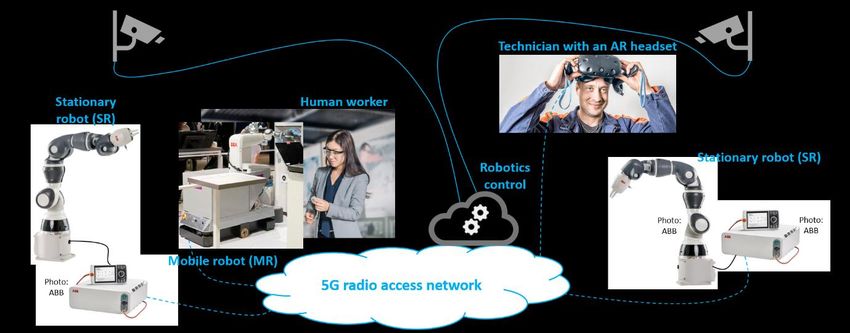
Document: Deliverable D2.1 Design of 5G-Based Testbed for Industrial
Robotics
Version: v1.0               Dissemination level: Public
Date: May 29, 2020          Status: Final

       Disclaimer
       This work has been performed in the framework of the H2020 project 5G-SMART co-funded by the
       EU. This information reflects the consortium’s view, but the consortium is not liable for any use that
       may be made of any of the information contained therein.

       This deliverable has been submitted to the EU commission, but it has not been reviewed and it has
       not been accepted by the EU commission yet.

       857008 5G-SMART                                                                                     1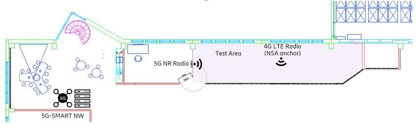
Document: Deliverable D2.1 Design of 5G-Based Testbed for Industrial
Robotics
Version: v1.0               Dissemination level: Public
Date: May 29, 2020          Status: Final

       Executive summary
       This document reports on the design of the 5G-based testbed at the Ericsson smart factory in Kista,
       Sweden, which is one of the trial sites for the 5G-SMART project. The testbed will be used for
       validating and evaluating 5G technologies against the requirements of three industrial robotics’ use
       cases from ABB. One use case relates to vision-based control of a collaboration between industrial
       robots, another to interaction between an industrial robot and a human worker on factory floor,
       while the remaining use case refers to visualization of factory-floor information by means of
       augmented reality (AR). The 5G testbed encompasses hardware equipment and software
       applications to realize the advanced use cases as well as the underlying 5G network infrastructure.

       A general overview of the three use cases is provided, followed by summarizing their main
       requirements from work for another 5G-SMART report, deliverable D1.1 “Forward looking smart
       manufacturing use cases, requirements and KPIs”. In order to identify key demands for building the
       5G testbed, a functional architecture for it is defined based on envisioned use case scenarios.
       Description of the functional architecture starts by abstracting and explaining essential robotics
       functions from the application perspective, then grouping them into functional components based
       on their planned roles in the 5G testbed, and finally presenting the communication interactions
       among the components in all three use cases by using sequence diagrams.

       The deliverable further specifies the equipment that is planned for the 5G testbed realization, also
       highlighting main hardware and software features of the equipment. For key software components
       which need to be prototyped, such as for robot motion planning and AR-based visualization, a
       functional design is described. The main functional components are “mapped” to equipment items,
       which illustrates how the robotics-related equipment will be inter-connected via the 5G network
       infrastructure and, especially, which data types will be exchanged over 5G wireless links. In the end,
       specific plans for implementing the 5G network infrastructure are laid out, including the type of 5G
       network architecture, spectrum and specific frequency bands to be used, but also on physical
       equipment deployment in the testing area at the Kista trial site.

       857008 5G-SMART                                                                                     2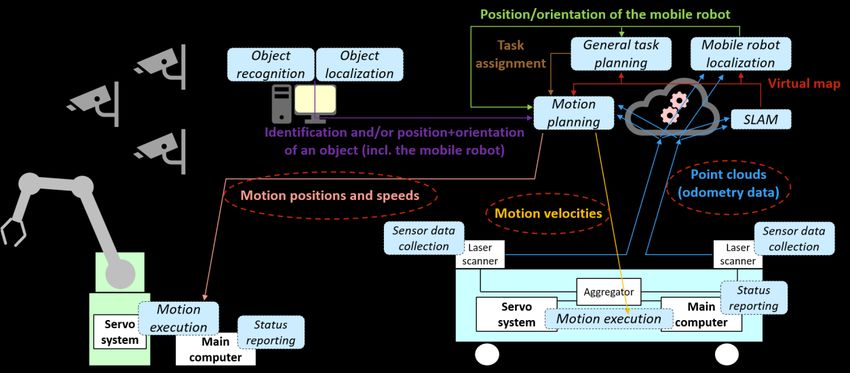
Document: Deliverable D2.1 Design of 5G-Based Testbed for Industrial
Robotics
Version: v1.0               Dissemination level: Public
Date: May 29, 2020          Status: Final

       Contents
       Executive summary ................................................................................................................................. 2
       1      Introduction .................................................................................................................................... 4
           1.1        Objective of the document ..................................................................................................... 4
           1.2        Structure of the document ..................................................................................................... 5
       2      Trial use cases ................................................................................................................................. 6
           2.1        Overview ................................................................................................................................. 6
           2.2        Expected benefits and key research objective ....................................................................... 7
           2.3        Summary of requirements ...................................................................................................... 8
       3      Functional architecture ................................................................................................................. 11
           3.1        Essential functions ................................................................................................................ 11
           3.2        Main functional components ................................................................................................ 14
           3.3        High-level communication interactions ................................................................................ 16
       4      Hardware and software equipment for the testbed .................................................................... 19
           4.1        Features of the equipment ................................................................................................... 19
           4.2        Mapping main functional components to the equipment ................................................... 20
           4.3        Functional design of key robotics software .......................................................................... 21
           4.4        Functional design of a prototype application for the AR visualization ................................. 23
       5      5G testbed deployment plan ........................................................................................................ 26
           5.1        Inter-connectivity configurations.......................................................................................... 26
           5.2        5G communication network deployment ............................................................................. 27
              5.2.1          Wireless infrastructure architecture............................................................................. 27
              5.2.2          Network solution for the Kista trial site ........................................................................ 28
       6      Conclusions ................................................................................................................................... 31
       7      References .................................................................................................................................... 32
       Appendix ............................................................................................................................................... 33
           List of abbreviations .......................................................................................................................... 33

       857008 5G-SMART                                                                                                                                          3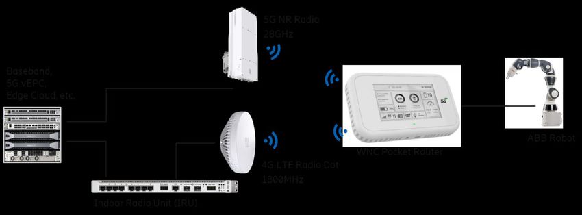
Document: Deliverable D2.1 Design of 5G-Based Testbed for Industrial
Robotics
Version: v1.0               Dissemination level: Public
Date: May 29, 2020          Status: Final

       1        Introduction
       In a continuous effort to boost productivity, industrial automation and, in particular, smart
       manufacturing are seeking to embrace state-of-the-art technologies from the domains of, e.g.,
       Internet of Things, artificial intelligence, and robotics. Industrial robots have a key role in smart
       manufacturing, allowing to relieve human workers of highly repetitive tasks as well as to improve
       their safety. The manufacturing landscape is also witnessing an increasing number of production
       lines, on which stationary robots need to collaborate with human workers or which are supported by
       mobile robots for transporting materials and goods.

       In such an ecosystem, 5G is expected to be a major wireless communication enabler. Besides
       offering native mobility support for mobile robots and other moving assets across large factory
       areas, 5G promises network performance guarantees tailored to the requirements of industrial
       applications. This would also facilitate disposing of cables for stationary machinery, which would, in
       turn, enable easier commissioning of production lines, but also their more flexible (re)configuration.
       5G-SMART focuses on validating and evaluating several 5G features, such as ultra-reliable and low-
       latency communications, and architectural aspects, such as Edge cloud computing, against the
       requirements of the most advanced manufacturing applications.

       1.1      Objective of the document
       Taking as an input work for 5G-SMART deliverable D1.1 “Forward looking smart manufacturing use
       cases, requirements and KPIs” [5GS20-D11], which defines in detail three industrial robotics’ use
       cases to be trialed at the Ericsson smart factory in Kista, this document presents the functional
       design and implementation plans for the 5G testbed that is going to be used for the trials.

       Driven by the motivation to produce a self-contained report for interested readers, a general
       overview of the advanced industrial robotics’ use cases is first given, followed by a summary of their
       main requirements from the work for deliverable D1.1 “Forward looking smart manufacturing use
       cases, requirements and KPIs”. In order to identify key demands for developing such a 5G testbed, a
       functional architecture for it is specified based on envisaged use case scenarios. Presentation of the
       functional architecture starts by explaining robotics-related functions from the application
       perspective, which are required to implement all three use cases. Examples of the robotics functions
       include robot motion planning and visual-based object recognition. These functions are then
       grouped into several functional components, based on envisaged roles of the components in the 5G
       testbed. Furthermore, the “high-level” communication interactions among the functional
       components are defined by means of sequence diagrams.

       This deliverable also specifies the equipment that is needed to build the 5G testbed. The equipment
       covers both the industrial robotics domain, such as commercial stationary robots from ABB, video
       cameras, and an augmented reality (AR) headset, as well as the 5G network infrastructure, such as
       Ericsson’s solutions for radio access and core networks. For all the equipment, its main hardware
       and software features are highlighted. Besides, a functional design is provided for key software
       which needs to be prototyped, e.g. robot motion planning and AR-based visualization. The identified
       functional components are “mapped” to the testbed equipment, which serves to illustrate how the
       robotics-related equipment will be inter-connected through the 5G network infrastructure and,

       857008 5G-SMART                                                                                     4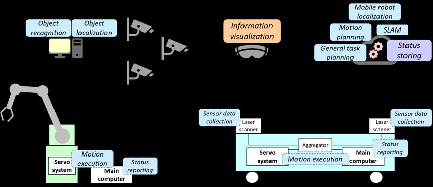
Document: Deliverable D2.1 Design of 5G-Based Testbed for Industrial
Robotics
Version: v1.0               Dissemination level: Public
Date: May 29, 2020          Status: Final

       especially, which data types will need to be exchanged over 5G radio. In the latter part, different
       inter-connectivity configurations for the robotics-related equipment are presented, which will allow
       studying system-wide tradeoffs between application-level requirements and network-level
       performance. In the end, specific plans for deploying and installing the 5G network solution are
       presented, including the 5G network architecture type, spectrum and specific frequency bands to be
       used for the trials, but also a schematic overview of the testing area at the Kista trial site.

       1.2      Structure of the document
       The rest of this document is structured as follows. Section 2 outlines the use cases that are to be
       trialed as well as their main requirements on the underlying 5G network. The functional architecture
       for the 5G-based testbed is presented in Section 3, including the essential functions to realize the
       use cases, main functional components from the application perspective and their testbed roles, and
       the communication interactions among these components. Section 4 lists the equipment that is
       required to implement the whole 5G testbed, along with the equipment’s hardware and software
       features. The 5G network solution and different equipment inter-connectivity configurations are
       specified in Section 5. Section 6 concludes the report.

       857008 5G-SMART                                                                                   5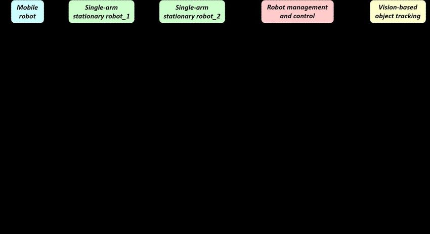
Document: Deliverable D2.1 Design of 5G-Based Testbed for Industrial
Robotics
Version: v1.0 Dissemination level: Public
Date: May 29, 2020 Status: Final
2 Trial use cases
Several 5G features, such as ultra-reliable and low-latency communications (URLLC), and
architectural aspects, such as Edge cloud computing, will be evaluated at the Kista trial site against
the requirements of three industrial robotics’ use cases. Each such use case (UC) revolves around a
factory-automation-like scenario that includes interactions between industrial robots, or between
industrial robots and human workers. The following scenarios are considered by the UCs:
• transport of materials and goods between stationary robots (i.e., robot workstations) by a
mobile robot (UC 1),
• safe movement of a mobile robot among human workers (UC 2), and
• supervision of factory-floor machinery and equipment by novel means of information
visualization (UC 3).
To realize efficient manufacturing processes, actions of each industrial robot, both a stationary robot
(SR) and a mobile robot (MR), are planned and inter-coordinated. For instance, the inter-
coordination encompasses collaboration between two SRs which process the same material or
between an MR and an SR, when the SR needs to place an object onto the MR.
2.1 Overview
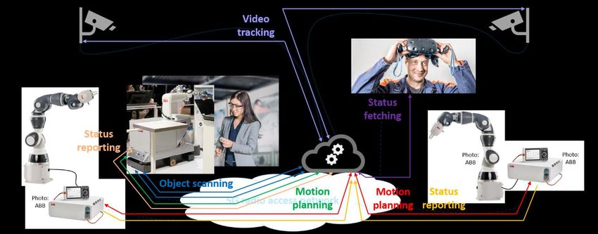
The overall setup for UC 1, UC 2, and UC 3 is illustrated in Figure 1. The setup assumes that all the
robotics-related equipment, except for a video camera system that “oversees” the trials area,
communicates over wireless to rest of the 5G testbed. UC 1 deals with the transport of materials and
goods by an MR, which is tasked to deliver an object from one SR to another. For that, a
collaboration of the robots is needed: after the MR approaches first SR, that SR will be tasked to
place the object onto the MR. Then, after the MR reaches the second SR, that SR is to pick up the
object from the MR. One of the main UC 1 ambitions is to deploy robotics intelligence for controlling
such collaborative operations to Edge cloud, a computing platform in the 5G network at close
proximity to the robotics equipment. The video camera system will be utilized as the main
information source for vision-based navigation of the MR towards SRs, but also for vision-based
tracking of the object in the pick and place operation.
Figure 1: A setup illustration for UC 1, UC 2, and UC 3
857008 5G-SMART 6
Document: Deliverable D2.1 Design of 5G-Based Testbed for Industrial
Robotics
Version: v1.0               Dissemination level: Public
Date: May 29, 2020          Status: Final

       UC 2 complements UC 1 by considering a human worker who moves on the factory floor that is
       populated with mobile robots, with the specific objective of navigating the MR by robotics
       intelligence in Edge cloud so that the MR avoids a physical contact with the human worker. The
       video camera system will be exploited as one of the main information sources for vision-based MR
       navigation relative to the current position of the moving human worker. Finally, UC 3 regards
       factory-floor technicians who are responsible for supervising the operation of industrial robots and
       other machinery based on gathered information. For UC 3, a technician will be equipped with an AR
       headset, which will allow displaying information on stationary and mobile robots by utilizing
       different gestures. Depending on the headset’s field of view, information display will report on an
       operational status of the robot that is physically closest to the technician, while also providing an
       indication of other robots which are near her/him, but not in the field of view. The objective in this
       use case is as well to evaluate using the video camera system for tracking the current position and
       orientation of the moving technician, i.e., her/his headset.

       2.2        Expected benefits and key research objective
       Software, which is responsible for, e.g., inducing electrical and mechanical parts to move one or
       more arms in an SR or the base of an MR, commonly executes on a hardware which is embedded in
       robots themselves. A key reason for that is to cater for demands on safety and execution efficiency.
       However, this also imposes several challenges. With respect to commissioning, an engineer usually
       needs to connect to each of industrial robots and configure their software one by one. A similar
       procedure is carried out if the robot software needs to be upgraded. In that sense, it would be
       beneficial if that software could be decoupled from the hardware in each industrial robot and
       executed on a common computing platform. This “offloading” of software would also enable
       simplification and miniaturization of the robot hardware, which might, in turn, lead to savings in
       overall robot footprint and manufacturing cost. Another positive impact regarding a robot hardware
       reduction might be achieved as follows: instead of equipping each industrial robot, e.g., with its own
       video camera that provides the robot with vision capabilities, a shared video system on a remote
       platform could be employed. Removing video cameras and, possibly, other peripheral devices might
       prove beneficial especially for mobile robots, for which the battery charge level is a critical working
       aspect. Furthermore, running different software on a common computing platform might pave a
       new way for introducing novel robotics services – for instance, one could integrate the planning of
       task assignments for industrial robots and a database on their operational status, which would allow
       an increased utilization of factory-floor machinery.

       An overarching research question for the three industrial robotics’ use cases is:

                  can 5G systems offer high-reliability and low-latency communication performance,

       that would

             1) support offloading robot software from its dedicated hardware to a common Edge cloud
                platform that is in close proximity to the robotics equipment, and
             2) support deploying other software for advanced industrial robotics applications (e.g., with
                regards to machine vision) onto that common platform,

                         so that critical operational demands of the use cases are satisfied?

       857008 5G-SMART                                                                                      7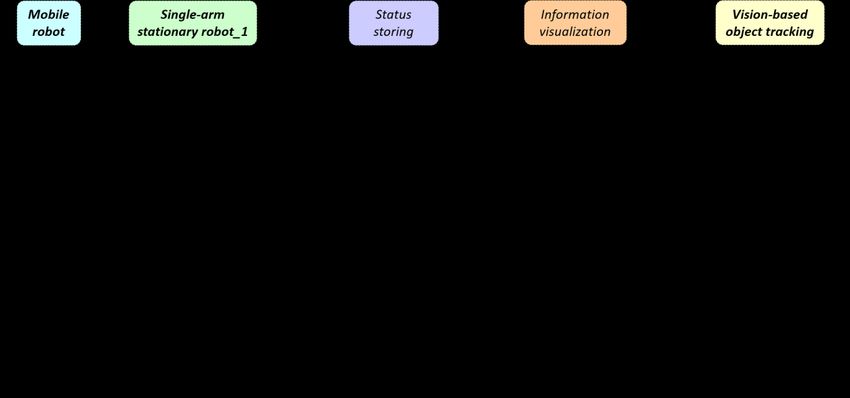
Document: Deliverable D2.1 Design of 5G-Based Testbed for Industrial
Robotics
Version: v1.0               Dissemination level: Public
Date: May 29, 2020          Status: Final

       2.3      Summary of requirements
       Work for 5G-SMART deliverable D1.1 “Forward looking smart manufacturing use cases,
       requirements and KPIs” [5GS20-D11] specifies in detail the three use cases to be set up at the Kista
       trial site. That specification includes a set of functional features which the 5G network needs to
       support for the use cases as well as non-functional requirements which the use cases impose on the
       underlying 5G network. This subsection provides a summary of the requirements, with the focus on
       performance-related metrics and their values planned for the 5G evaluation.

       The performance requirements are expressed per each of the main communication streams that are
       presented in the use case specification. Communication streams carry the data among key entities in
       the 5G testbed that is needed to achieve different features of the use cases (Figure 2). Most of the
       streams will be exchanged over 5G wireless links, except for the video tracking streams from the
       video camera system that will exploit wired connectivity. Further explanations on these
       communication aspects can also be found in the remaining part of this report.

                     Figure 2: An overview of communication streams in the Kista trial site use cases

       The performance requirements put forth are summarized in Table 1 and Table 2, and correspond to
       the application perspective of the communication services. The outlined subset of the metrics is
       selected to briefly explain the need for 5G wireless connectivity. Average data rates are highlighted
       for both 5G radio downlink (DL) and uplink (UL). For the two motion planning communication
       streams in Table 1 as well as status fetching in Table 2, two-way end-to-end (E2E) latency, or round-
       trip time, is assumed. When it comes to characterizing the communication streams in terms of traffic
       models, then two major aspects are considered: communication periodicity and communication
       determinism. The periodicity relates to transmitting messages with a certain time interval between
       the consecutive transmissions. If that transmission interval is known and repeated, then the
       communication is said to be periodic, otherwise it is aperiodic. The determinism regards the time
       between the transmission and the reception of a message. If that time is bounded, then the
       communication is said to be deterministic, otherwise it is non-deterministic.

       857008 5G-SMART                                                                                    8
Document: Deliverable D2.1 Design of 5G-Based Testbed for Industrial
Robotics
Version: v1.0 Dissemination level: Public
Date: May 29, 2020 Status: Final
End-to-end Communication
Communication Average data
latency service Remarks
stream rate
(max.) availability
Deterministic and periodic
Motion planning DL < 1 Mbit/s < transfer_ communication, with
≥ 99.99 %
for SR UL < 1 Mbit/s intervalSR transfer_intervalSR of
[5-40] ms
Deterministic and periodic
Motion planning DL < 0.5 Mbit/s < transfer_ communication, with
≥ 99.99 %
for MR UL < 0.5 Mbit/s intervalMR transfer_intervalMR of
[10-50] ms
DL < 2 Mbit/s To be
Object scanning To be explored Periodic communication
UL < 2 Mbit/s explored
Table 1: A summary of performance requirements from UC 1 and UC 2
Motion planning for both SR and MR employs sending motion commands and receiving
acknowledgments for them. It is important to note that these communications are not only periodic,
with a pre-set transfer interval between sending two consecutive commands, but also deterministic.
Such a characterization on determinism stems from motion planning design and its correct
operation assuming that next motion command is sent after the previous command is
acknowledged. For that reason, the two-way E2E latency needs to be lower than the transfer
interval value, while, given the communication service availability demand, it is allowed that only
one in 10000 such commands is not acknowledged in the due time. Object scanning relates to a laser
scanner on-board MR that collects “readings” of physical objects and, in such a way, recognizes
potential obstacles in the MR’s environment (the illustration in Figure 2 assumes two such scanners
on the MR).
End-to-end Communication
Communication Average data
latency service Remarks
stream rate
(max.) availability
Status reporting DL < 1 Mbit/s Not Non-deterministic and
Not relevant
for SR UL < 1 Mbit/s relevant aperiodic communication
Status reporting DL < 1 Mbit/s Not Non-deterministic and
Not relevant
for MR UL < 1 Mbit/s relevant aperiodic communication
Deterministic
DL < 5 Mbit/s
Status fetching < lag ≥ 99.0 % communication, lag of
UL < 1 Mbit/s
[100-200] ms
Table 2: A summary of performance requirements from UC 3
The status reporting streams for SR and MR target storing the robots’ operational status in a
centralized data repository, and both stream types are categorized as non-deterministic and
aperiodic. This is due to a common utilization of reliable transport protocols for such purpose. Status
fetching, on the other hand, refers to acquiring information which will be visualized in the AR
headset from the centralized data repository. To avoid the technician wearing such headset notice
any lags regarding the time interval between issuing a respective fetching command and displaying
the information in the headset, the two-way E2E latency needs to be lower than a lag value.
857008 5G-SMART 9Document: Deliverable D2.1 Design of 5G-Based Testbed for Industrial
Robotics
Version: v1.0 Dissemination level: Public
Date: May 29, 2020 Status: Final
The examples of both stationary and mobile robots and their strict requirements on bounded
communication latency and communication service availability with respect to the motion planning,
as well as of a technician with the AR headset who moves around factory floor and the demand on
timely delivery of robot status information to be visualized, clearly motivate leveraging 5G
technologies and their service of URLLC.
857008 5G-SMART 10Document: Deliverable D2.1 Design of 5G-Based Testbed for Industrial
Robotics
Version: v1.0 Dissemination level: Public
Date: May 29, 2020 Status: Final
3 Functional architecture
This section presents the functional architecture related to envisioned use case scenarios, which is
the key input for designing overall 5G testbed. The essential functions to realize the three use cases,
such as motion planning for an SR, motion planning for an MR, object recognition, and information
visualization, are described in subsection 3.1. Based on the planned roles in the 5G testbed, these
essential functions are grouped into main, application-perspective components and presented in
subsection 3.2. An anticipated sequence of operational steps across all three use cases and the
associated “high-level” communication interactions among these functional components are
specified and illustrated in subsection 3.3.
3.1 Essential functions
Scenarios of UC 1, UC 2, and UC 3 are based on two robot actions: moving an arm of an SR and
moving the base of an MR. In order to regulate movement path, or motion, of a robotic arm so that
it achieves a needed action, a control process is executed (Figure 3). This control process involves a
motion planning function that periodically computes sequential arm positions needed to reach the
target motion position. The computed arm positions are sent as references to a motion execution
function, along with the value of motion speed for reaching each such position. After receiving a
motion reference with the value of a future position, the motion execution function induces
electrical and mechanical parts to move a given robotic arm to that position. For each received
motion reference, motion execution feeds back the actual position of the arm to the motion planning
function to facilitate monitoring of reaching the motion target. When an SR contains more than one
arm, then for each of them a separate control process would formally be executed. However, the
control process could also be implemented to have a single motion planning instance regulating
movement of multiple robotic arms.
Figure 3: Simplified control processes for stationary and mobile robots
A similar control process is employed for the base of an MR (Figure 3). However, for an MR to be
autonomous, at least two other functions need to be in place, namely simultaneous localization and
mapping (SLAM) and mobile robot localization. The SLAM function is used to produce a
857008 5G-SMART 11Document: Deliverable D2.1 Design of 5G-Based Testbed for Industrial
Robotics
Version: v1.0 Dissemination level: Public
Date: May 29, 2020 Status: Final
representation of an MR’s physical environment in the form of a virtual map, so that the MR can
navigate through the environment and avoid any potential obstacles. When it comes to realizing it,
SLAM most commonly relies on a “pre-operational” run of an MR and using, possibly, different types
of sensors on-board the MR to collect so-called point clouds. Point clouds represent “readings” of
physical objects and are exploited to produce the virtual map of the environment. In parallel to
acquiring point clouds, SLAM is also used to determine the MR’s initial location on the virtual map.
After the virtual map is produced by means of SLAM, mobile robot localization is responsible for
tracking the actual position and orientation of the MR as it moves in physical space. For that
purpose, mobile robot localization takes advantage of the virtual map as well as point clouds which
are continuously collected. Both the virtual map and the actual position of the MR are fed into
motion planning, which then calculates desired future position of the MR base. Motion references
for the MR base may include information on speeds and steering angles for the base wheels. After
receiving this input, motion execution drives the base towards a destined position.
An MR may be equipped with one or more robotic arms, which are mounted on top of its base. In
that sense, this report distinguishes between the functions of motion planning for robotic arm,
which may regard any arm of either SRs or MRs, and of motion planning for mobile robot base,
which relates only to MR. When robotic arms of a given MR are employed in tasks, then the control
process of the whole MR might also comprise a coordination between planning motion of the MR
base and of one or more robotic arms. An illustration of the control process for an MR with two
robotic arms is shown in Figure 4. It is worthwhile emphasizing that the instances of motion planning
for two or more robotic arms could also be realized as a common function for the purposes of
harmonizing motion among the arms.
Figure 4: Simplified control process for an MR with two arms
One of the ambitions in UC 1 and UC 2 is to achieve mobile robot navigation and the robot
collaboration by using video cameras, which are e.g. wall-mounted, as the main source of
information. More broadly, the plan is to use the same set of video cameras for several essential
functions across UC 1, UC 2 and UC 3:
857008 5G-SMART 12Document: Deliverable D2.1 Design of 5G-Based Testbed for Industrial
Robotics
Version: v1.0 Dissemination level: Public
Date: May 29, 2020 Status: Final
• object recognition – to aid in distinguishing, e.g. via marker tag detection, between SR, MR,
the object being handed over in the collaborative robot operation, and a human worker
moving on the factory floor; and
• object localization – to aid in determining the position of an object and its orientation in
space, which is used to help tracking the human worker relative to the MR in UC 2, but also
to determine the field-of-view of the AR headset in UC 3.
The function of object recognition is differentiated from object localization to support the usages
that do not call for, e.g., determining the position and orientation of an object. The function of
object localization will be regarded separately from mobile robot localization, to support specific
scenario aspects in the use cases.
Another relevant function across all use cases is general task planning, which is responsible for
assigning “high-level” tasks to industrial robots. One such task would be instructing an MR (“worker
X”) to transport required materials from one SR (“worker Y”, also referred to as a “robot
workstation”) to another SR (“worker Z”), while another task would be commanding “worker Y” to
pick material and place it on “worker X” or commanding “worker Z” to pick the material from
“worker X”. To facilitate SLAM, object recognition and object localization, an auxiliary function of
sensor data collection is mandatory. The latter function is a generalization regarding different data
sources, including video cameras and laser scanners. Status reporting addresses the capability of
industrial robots to periodically publish information on their operational status, such as time in
production for SRs and battery charge level for MRs, while status storing represents the function
that allows to collect status information on different industrial robots into a centralized data
repository. A key function for UC 3 is information visualization, which exploits the information
gathered by status storing to display it in a systematic way (in this case, by means of AR techniques).
A summary of key functions from the industrial robotics domain is given in Table 3. Besides a short
description, the usage of each function is noted: for SR, MR, or it is universal, meaning that the
function is applied to other UC “actors” as well.
857008 5G-SMART 13Document: Deliverable D2.1 Design of 5G-Based Testbed for Industrial
Robotics
Version: v1.0 Dissemination level: Public
Date: May 29, 2020 Status: Final
Function Description Usage
General task Assigns tasks to industrial robots SR, MR
planning
Motion planning for Computes motion references for a single robotic arm SR
robotic arm
Motion planning for Computes motion references for the base of an MR MR
mobile robot base
Motion execution Receives motion references and induces motion of SR, MR
moveable robot parts
Status reporting Publishes information on operational status of an SR, MR
industrial robot
Status storing Collects information on operational status of different Universal
industrial robots
SLAM Produces a virtual map of the physical environment Universal
Object recognition Identifies an object on the factory floor (e.g., determines Universal
whether it is an SR or an MR)
Object localization Estimates position and orientation of an object based on Universal
machine vision principles
Mobile robot Estimates position and orientation of an MR based on the MR
localization virtual map and point clouds
Sensor data Retrieves data about the factory floor environment to Universal
collection support other functions such as SLAM
Information Displays the information gathered by status storing in a Universal
visualization systematic way
Table 3: Summary of key functions required to realize the trial use cases
3.2 Main functional components
The functional architecture for the 5G testbed identifies the main components from the application-
level perspective, i.e., considering specifics of the three use cases which do not depend on the
underlying 5G communication infrastructure. Each such component is defined to contain a minimum
number of the afore-presented functions, having in mind key challenges across UC 1, UC 2, and UC 3
as well as the specified UC scenarios. The following components are identified (Figure 5):
• Single-arm stationary robot – represents an SR with one arm, with its motion planning
function offloaded from the SR hardware;
• Mobile robot – corresponds to an MR that does not comprise robotic arms, with its motion
planning function also offloaded from the MR hardware;
• Robot management and control – acts as a centralized “brain” for all industrial robots that is
responsible for planning both their high-level tasks and specific motions; and
• Vision-based object tracking – allows identifying different components and/or determining
their position and orientation based on computer vision.
857008 5G-SMART 14Document: Deliverable D2.1 Design of 5G-Based Testbed for Industrial
Robotics
Version: v1.0 Dissemination level: Public
Date: May 29, 2020 Status: Final
Figure 5: Main functional components
The MR comprises one instance of motion execution and two instances of sensor data collection,
which capture its overall role across all UCs. Motion execution converts respective references into
movement of the MR base. The sensor data collection instances relate to two laser sensors, which
are producing point clouds for SLAM and mobile robot localization. One of the sensors is placed, e.g.,
at front of the MR base and the other is located at rear of the base. Like the MR, Single-arm
stationary robot (SASR) holds one instance of motion execution, which deals with the SR’s arm. On
the contrary, no sensor data collection instances are shown for the SR, since its external sensors are
not required for any of the three use cases. Both components encompass status reporting, but
interaction of that function towards Robot management and control is omitted from the figure for
the readability purposes.
Robot management and control (RMC) is the most complex component, consisting of general task
planning, motion planning, SLAM, and mobile robot localization. SLAM is envisaged to collect point
clouds from the laser sensors and then centrally generate the virtual environment map. In a more
general case, that process may involve multiple instances of MR, which would then provide more
“readings” of physical objects and allow to create a more accurate map. General task planning is
envisaged to assign tasks to all industrial robots, both the MR type and SASR. Combined with robot
reports which are received by RMC, the general task planning function can take advantage of the
virtual map produced by SLAM to improve overall utilization of robots. Based on the computed task
assignments and the produced virtual map, motion planning regulates movement of the MR and the
SASR. For the latter objective, motion planning further exploits outputs of Vision-based object
tracking or VOT (Figure 5). Mobile robot localization is used to determine the current position and
orientation of a specific MR as it is navigated through the physical space. Object recognition and
857008 5G-SMART 15Document: Deliverable D2.1 Design of 5G-Based Testbed for Industrial
Robotics
Version: v1.0 Dissemination level: Public
Date: May 29, 2020 Status: Final
object localization, on the other hand, are employed to supply the current position and orientation
of the MR as it approaches a SASR for the pick and place operation, but also indicate, e.g., when an
object is placed on the MR by a SASR.
Status storing and Information visualization are both considered as the main components in the
functional architecture for the 5G testbed.
3.3 High-level communication interactions
Figure 6 shows the sequence diagram that illustrates essential interactions in UC 1 among the
identified components. In order to achieve UC 1 objectives, MR is first tasked to collect point clouds
describing the physical environment and send that sensor data to the SLAM function in RMC. Based
on the received input, SLAM produces the corresponding virtual map. (Alternatively, point clouds
could be collected by some other means, e.g. via video cameras, and used to produce such a map,
which would then be loaded to RMC for further usage.) Assuming that MR is already in the field of
view of VOT, VOT identifies it (e.g. via its unique marker) and then continuously tracks its position
and orientation further on. At a certain point in time, general task planning of RMC assigns MR the
task of transporting an object from Single-arm stationary robot_1 (SASR_1) to Single-arm stationary
robot_2 (SASR_2). Motion planning of RMC then starts navigating MR by periodically sending motion
references and receiving motion feedback. Just after MR starts moving, its actual position and
orientation are also estimated by mobile robot localization in RMC (that part of the overall scenario
is not shown in Figure 6). Since, as compared to mobile robot localization, VOT can also recognize a
particular SASR, the position/orientation information from VOT is exploited by motion planning
when MR is near a SASR and needs to be put in a right position for the pick and place operation.
Before that, the position/orientation information from mobile robot localization is used by RMC to
compute future motion references for MR.
Figure 6: A high-level interaction in UC 1
857008 5G-SMART 16Document: Deliverable D2.1 Design of 5G-Based Testbed for Industrial
Robotics
Version: v1.0 Dissemination level: Public
Date: May 29, 2020 Status: Final
After RMC determines that MR reached vicinity of SASR_1, general task planning in RMC first
transfers from mobile robot localization to utilizing VOT as the main source of MR’s position and
orientation. This is done to help navigate MR more accurately to the position next to SASR_1 where
the pick and place operation will be carried out. General task planning then assigns SASR_1 with the
task of placing an object onto MR. For that purpose, RMC also relies on VOT to track position of the
transferred object and motion planning calculates motion references for SASR_1 until the object is
placed onto MR. After that, RMC stops computing motion references for SASR_1 and could assign
other tasks to it. Very similar sequence of events and messages applies for navigating MR towards
SASR_2 and tasking SASR_2 to pick the object from MR, so those steps are omitted from Figure 6.
Continuing from Figure 6 and moving MR, the sequence diagram in Figure 7 outlines communication
interactions among the main components to realize the UC 2 scenario. The actual position and
orientation of MR are still tracked by mobile robot localization in RMC and by VOT. When VOT
recognizes a human worker (e.g. by having her/him wear a unique marker tag), it notifies RMC of
that, starts also tracking the position and orientation of the human worker, and continuously sends
that information to RMC. The notification may be used by motion planning in RMC to, e.g., decrease
the moving speed of MR out of precaution. If RMC estimates that the human worker is approaching
MR and getting close to it, motion planning in RMC proactively guides MR away and around the
human worker. In the latter process, a pre-defined safety area around MR is considered. It is
important to emphasize that UC 2 also considers functional safety aspects, which require, e.g., MR
not to solely depend on communication with RMC to stop it if the human worker gets too close to
the robot, but as well to employ sensor data collection on-board MR to detect her/him.
Figure 7: A high-level interaction in UC 2
Figure 8 shows functional cooperation in UC 3. During the entire operational phase, SASR_1, SASR_2
and MR continuously report status information to the Status storing component. At a certain point
in time, a technician who is equipped with the AR headset starts moving on the factory floor, also
getting recognized by VOT (e.g. by having a marker tag attached to the headset). While the
technician is present in the area covered by VOT, it constantly sends tracked position and orientation
of her/his headset in the physical environment to the Information visualization component. That
857008 5G-SMART 17Document: Deliverable D2.1 Design of 5G-Based Testbed for Industrial
Robotics
Version: v1.0 Dissemination level: Public
Date: May 29, 2020 Status: Final
way, Information visualization can exploit the position/orientation information determined by VOT
and regularly estimate the technician’s field-of-view. After MR is recognized by VOT, the information
on position/orientation of the technician is extended to include that of MR as well. By receiving
actual position/orientation of both the technician and MR, Information visualization can compute
their relative distance and orientation. When MR enters the field-of-view of the AR headset,
Information visualization “captures” that event and fetches status information on MR from Status
storing. Then, it updates the technician’s display with the retrieved information. Another option
would be for Information visualization to begin pre-fetching the status information when it
estimates that MR will enter the field-of-view.
Figure 8: A high-level interaction in UC 3
The technician continues to move on the factory floor and reaches such relative position and
orientation that, e.g., both MR and SASR_1 are seen through the headset’s display. Information
visualization then calculates the distances between the technician, MR and SASR_1, allowing it to
determine which of the two robots is closer to the technician (that calculation step is not shown in
Figure 8). If that robot is SASR_1, Information visualization stops augmenting the technician’s display
with the status of MR, retrieves operational status of SASR_1 from Status storing, and visualizes the
new information to the technician.
857008 5G-SMART 18Document: Deliverable D2.1 Design of 5G-Based Testbed for Industrial
Robotics
Version: v1.0 Dissemination level: Public
Date: May 29, 2020 Status: Final
4 Hardware and software equipment for the testbed
Based on the functional architecture, this section specifies the primary equipment that is planned for
realization of the 5G testbed. It refers both to 5G network components, such as communication
routers and radio units, and to robotics-related equipment, e.g. stationary robot arms and video
cameras. Essential hardware and software features of all the equipment are listed in subsection 4.1
for the sake of completeness, with more details on the 5G network components provided in
Section 5. A “mapping” of the presented functional components to the 5G testbed equipment is
outlined in subsection 4.2, which further illustrates data types to be exchanged over 5G wireless
links. A functional design for key software applications which will realize the functional components
from the application perspective is described in subsection 4.3 and subsection 4.4.
4.1 Features of the equipment
Single-arm stationary robots: ABB’s IRB 14050, Single-arm YuMi® Collaborative Robot [YuMi], with
an external hardware box that contains the main computer and runs operating system (OS)
RobotWare 7 in it; Externally Guided Motion (EGM) feature in RobotWare will be used to receive
motion references (on position and speed) for the robot.
Mobile robot: ABB’s “in-house” research platform with an Intel NUC main computer on the MR base
that runs Robot Operating System (ROS), the Melodic edition [ROS], and with two 2D laser scanners,
for which the SICK TiM781S LiDAR model is planned.
Video camera system: at least three RGB (red, green, and blue) cameras connected over Gigabit
Ethernet to a personal computer are planned, aiming to use the Genie Nano-1GigE family of cameras
by Teledyne DALSA [Teledyne].
Marker tags: at least six AprilTags [ATag] are planned; two for SASRs (for object recognition), one for
MR (for object recognition and object localization), one for the human worker in UC 2 (for object
recognition and object localization), one for the technician’s AR headset in UC 3 (for object
recognition and object localization), and one for the object being handed over in the collaborative
robot operation (for object recognition and object localization).
AR headset: Microsoft HoloLens 2 [HoloLens2], which is worn by a technician and, among other
things, supports a USB Type-C connection (that connection is planned also to serve as the
communication interface towards the 5G testbed). The AR headset will be equipped with 64 GB of
Flash memory storage and 4 GB of DRAM memory. HoloLens 2 is light-weight (566 g) and equipped
with a Lithium-Ion battery, which offers 2-3 hours of active use.
5G communication router (User Equipment, UE): Several units of the 5G router, with both 4G and
5G modems, are provided by Wistron NeWeb Corporation (WNC). It uses a Qualcomm®
Snapdragon™ X50 chipset. The router is integrating 5G communication capabilities into the robots
and the AR headset.
5G radio access network: In the 5G Non-standalone Architecture (NSA) both 4G LTE and 5G NR
radios are used. The 4G LTE anchor handles all control traffic and is implemented with Ericsson Radio
Dot System. Data traffic is primarily transmitted over 5G NR, which is handled by a small footprint,
857008 5G-SMART 19Document: Deliverable D2.1 Design of 5G-Based Testbed for Industrial
Robotics
Version: v1.0 Dissemination level: Public
Date: May 29, 2020 Status: Final
millimeter Wave (mmWave) radio. Baseband processing is managed by Ericsson’s Baseband Units.
The radio network runs on commercially available software, deployed in the Baseband Units.
5G core network: A virtualized Evolved Packet Core solution, based on 3GPP Release 15, that also
supports 5G NR as a radio access technology is installed in a small 19” rack. This rack further includes
switches, routers and network equipment necessary for internal and remote access. The core
network runs on commercially available software.
Edge cloud platform: Separate computing resources, co-located with the 5G core network, will be
used to execute additional software and are referred to as the application server. The application
server is implemented on a multi-core server, which also runs virtual machines (VMs) for some
network-related functionality.
4.2 Mapping main functional components to the equipment
Figure 9 presents how main functional components, which are identified in Section 3, “map” to
previously listed industrial robotics equipment. Functions of SASR will be provided by ABB’s single-
arm YuMi® robot. Main computer in the YuMi’s external hardware box runs a Robot Web Services
(RWS) server that provides information on the robot’s operational status. Function of motion
execution is divided between the robot’s main computer and its internal servo system, with the
RobotWare OS in the main computer receiving motion references for the robotic arm via its EGM
module. The MR functions will be implemented by the afore-mentioned ABB’s research platform.
Like in YuMi®, the on-board NUC main computer executes software which gathers status
information on the MR such as its battery charge level. Motion execution is jointly realized in the
servo system of the MR base and in the NUC computer, with the latter hardware unit running the
ROS platform which will receive motion references from RMC. Two laser scanners will collect point
clouds for SLAM and mobile robot localization. More functional design specifics on that software can
be found in the next subsection.
VOT corresponds to the video system with RGB cameras. Video cameras are connected over Gigabit
Ethernet to a personal computer. Functions of object recognition and object localization will be
realized by a prototype software, which will run in the personal computer local to the video
cameras. Such a design decision of retaining video processing “close” to the source of that data also
enables a rational usage of 5G network resources. RMC will be achieved by a set of software
applications, where each of them executes an RMC function: general task planning, SLAM, mobile
robot localization, and motion planning. All that RMC software will run “on top of” computing
resources of the Edge cloud platform. A functional design for these software components is given in
the next subsection. In addition, the Status storing function will be realized by a software
implementation of the status data repository that will also exploit the Edge cloud computing
resources (Figure 9). Relevant for UC 3, Information visualization will be offered by a prototype
application for AR-based visualization that is executed in the HoloLens 2 headset. A set of functional
design requirements with respect to the AR-related software can be found in subsection 4.4.
857008 5G-SMART 20Document: Deliverable D2.1 Design of 5G-Based Testbed for Industrial
Robotics
Version: v1.0 Dissemination level: Public
Date: May 29, 2020 Status: Final
Figure 9: Mapping main functional components to the defined testbed equipment
4.3 Functional design of key robotics software
Previously explained robotics functions will be implemented in the form of software components.
This subsection describes a functional design behind general task planning, SLAM, mobile robot
localization, motion planning (which combines planning for both the MR base and arms of the YuMi®
robots), motion execution, object recognition, object localization, and status reporting.
SLAM will receive point clouds from laser scanners of the MR and construct a virtual map of the
physical environment that is previously unknown to the MR (Figure 10). The point cloud flows are
marked with a dashed ellipse, indicating that the data will be exchanged over a 5G wireless link. The
plan is to execute the SLAM software only at the beginning of each experiment/demo run, when a
virtual map of the environment is non-existing. Each point cloud will be described with a (x, y, z)
value triplet, which represents a coordinate system point. This software component will consider
two coordinate systems. A global coordinate system will represent the real world, serve as the basis
for constructing the virtual map, and be used for expressing position of, e.g., the MR’s centroid in
the virtual map. On the other hand, a local coordinate system will be associated to the MR and used
for expressing, e.g., position of the MR’s laser scanners relative to the virtual map. The map of the
physical environment will be grid-based, represented by a set of cells. Each cell will be described
with the value of “0” (which means there is no object, i.e., an MR obstacle, associated with the cell),
“1” (the cell is “occupied”, i.e., there is an obstacle associated with the cell), or “X” (status of the cell
is unknown). The probability that a virtual map cell is occupied depends on the number of points
from the point clouds that are contained in the cell. The SLAM component will be developed based
on the ROS 2D navigation stack [ROSnav]. The latter navigation stack will also be used for the
communication purposes, since point clouds from the laser scanners will be encapsulated into ROS
messages and then sent to SLAM. In parallel to constructing the virtual map, SLAM will also
determine initial position of the MR base’s centroid in the virtual map.
857008 5G-SMART 21Document: Deliverable D2.1 Design of 5G-Based Testbed for Industrial
Robotics
Version: v1.0 Dissemination level: Public
Date: May 29, 2020 Status: Final
Figure 10: Data exchange among key robotics software. Dashed ellipses emphasize the data flows that will be
sent via 5G wireless links.
After the virtual map is created and saved, mobile robot localization is a software component that
will estimate position (x, y) and orientation (θ) of the MR with respect to the virtual map, and
support motion planning. Besides using the virtual map from SLAM, mobile robot localization will
receive point clouds from the MR’s laser scanners as well as odometry data, i.e., an estimation of the
MR’s current position based on speeds and steering angles of the robot’s wheels. As for SLAM, this
component will be realized based on the ROS 2D navigation stack [ROSnav]. Mobile robot
localization will feed the estimated position/orientation information to the motion planning
component as a complementary input to the one from the object localization component. As
previously explained, this is to accommodate different UC scenarios for which the MR is navigated,
and the required position/orientation precision needed for them.
The software components for object recognition and object localization will be based on a marker
tag detection, assuming that each “object” which needs to be recognized and/or localized (each
YuMi® robot, the MR, the human worker, the technician’s AR headset, and the object handed over
between the robots) is equipped with a marker tag. As the input, these components will receive RGB
images from the video cameras and then recognize all marker tags in the field-of-view of the
cameras, while also estimating position and orientation of each “object” that is recognized in the
marker detection process. The position and orientation information will be estimated for each RGB
image and then sent to the motion planning component. For realizing object recognition and object
localization, the AprilTag visual system software will be considered [ATag].
Considering the virtual map received from SLAM, general task planning will send out “high-level”
task assignments. As an example for the MR, a task assignment comprises targeted position and
orientation that the robot needs to reach on the virtual map. Furthermore, the general task planning
component will be able to decide if motion planning can exploit mobile robot localization (e.g. for
“regular” navigation) or to rely on the position/orientation information from the object localization
component. The visual-based motion planning mode will be used, e.g., for the object handover
between a YuMi® robot and the MR. For both stationary and mobile robots, an input to the general
857008 5G-SMART 22You can also read