Navigation of a magnetic micro robot through a cerebral aneurysm phantom with magnetic particle imaging
←
→
Page content transcription
If your browser does not render page correctly, please read the page content below
www.nature.com/scientificreports
OPEN Navigation of a magnetic
micro‑robot through a cerebral
aneurysm phantom with magnetic
particle imaging
Anna C. Bakenecker 1,2*, Anselm von Gladiss 1, Hannes Schwenke3, André Behrends1,2,
Thomas Friedrich1,2, Kerstin Lüdtke‑Buzug1, Alexander Neumann1, Joerg Barkhausen4,
Franz Wegner4,5 & Thorsten M. Buzug1,2,5*
Cerebral aneurysms are potentially life threatening and nowadays treated by a catheter-guided coiling
or by a neurosurgical clipping intervention. Here, we propose a helically shaped magnetic micro-robot,
which can be steered by magnetic fields in an untethered manner and could be applied for a novel
coiling procedure. This is shown by navigating the micro-robot through an additively manufactured
phantom of a human cerebral aneurysm. The magnetic fields are applied with a magnetic particle
imaging (MPI) scanner, which allows for the navigation and tomographic visualization by the same
machine. With MPI the actuation process can be visualized with a localization accuracy of 0.68 mm
and an angiogram can be acquired both without any radiation exposure. First in-vitro phantom
experiments are presented, showing an idea of a robot conducted treatment of cerebral aneurysms.
Magnetic actuation (MA) is of great potential for a variety of different application scenarios. The advantage of
applying external magnetic fields to steer a robot is that no onboard energy supply is needed and miniaturiza-
tion towards the micrometer scale becomes possible. Steerable capsules for the inspection of the gastrointestinal
tract1,2, millimeter-sized robots for vascular a pplications3–5 and micrometer-sized helical s wimmers6,7 have been
already developed. They enable targeted drug delivery8,9 and can be deployed inside very small cavities, such as
the eye10,11. However, the tomographic visualization in real-time remains challenging. Medical imaging tech-
niques such as X-ray-based modalities, Magnetic Resonance Imaging (MRI), Ultrasound or PET have been inves-
tigated, but they show disadvantages in either spatial or temporal resolution or utilize ionizing r adiation9,12,13.
Magnetic Particle Imaging (MPI) appears as a highly promising imaging modality for tracking the move-
ment of magnetic r obots13. MPI is a medical imaging technique, which has been intensively developed within
the last fifteen years and is nowadays at the stage of preclinical investigations. It utilizes the nonlinear magneti-
zation behavior of superparamagnetic iron oxide nanoparticles (SPIONs) and visualizes their concentration
distribution14. MPI is of great interest for vascular i nterventions15 and n
euroimaging16. A beating mouse-heart
as well as SPION-coated interventional devices have been visualized so f ar17,18. The advantage of combining
MA with MPI is that the magnetic fields generated by an MPI scanner allow MA as well, therefore no imaging
modality has to be integrated into an actuation setup or vice versa, despite that MPI is capable of tomographic
real-time imaging without the need of ionizing radiation and nephrotoxic contrast a gents17. An MPI scanner
induces a magnetic force by its gradient field, such that magnetic devices19,20 or particles21,22 can be moved.
Furthermore, a rotation of magnetic devices or particles can be generated by using the homogeneous magnetic
fields of the focus fields and applying alternating currents to the coils resulting into a rotating field vector4,23,24.
In comparison, MRI machines also feature a magnetic gradient field, which can be utilized for MA. However,
the gradient strength is smaller and therefore, the force applied is weaker. Furthermore, rotating magnetic fields
1
Institute of Medical Engineering, University of Lübeck, Ratzeburger Allee 160, 23562 Lübeck,
Germany. 2Fraunhofer Research Institution for Individualized and Cell-Based Medical Engineering IMTE,
Mönkhofer Weg 239a, 23562 Lübeck, Germany. 3Department of Neuroradiology, University Hospital
Schleswig-Holstein, Campus Lübeck, Ratzeburger Allee 160, 23562 Lübeck, Germany. 4Department of
Radiology and Nuclear Medicine, University of Lübeck, Ratzeburger Allee 160, 23562 Lübeck, Germany. 5These
authors contributed equally: Franz Wegner and Thorsten M. Buzug. *email: bakenecker@imt.uni-luebeck.de;
thorsten.buzug@imte.fraunhofer.de
Scientific Reports | (2021) 11:14082 | https://doi.org/10.1038/s41598-021-93323-4 1
Vol.:(0123456789)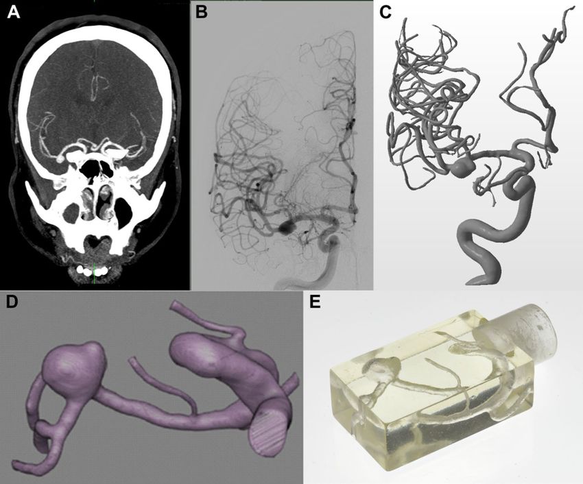
www.nature.com/scientificreports/
cannot be applied with an MRI machine and SPIONs are visualized as a cancellation of signals in MRI. Hence,
the localization can be imprecise, and a quantification of tracer material is not possible.
The navigation of robots towards a targeted position in an untethered manner opens the possibility to reach
regions of the body, which are difficult to access even by interventional techniques. Nowadays, endovascular
interventions are increasingly replacing surgical procedures as they are related to less (peri)-operative complica-
tion rates and faster rehabilitation of the patients. Thus, catheter-guided endovascular interventions have become
the standard therapy for the treatment of numerous vascular diseases. Major parts of the vascular system can
be reached minimal invasively including a wide range of therapeutic options, e.g. balloon dilatation and stent
implantation, thrombectomy of occluded vessels and embolization/coiling of aneurysms.
Typical localizations of aneurysms are the cerebral arteries. Between 3 and 5% of the population carry cerebral
aneurysms25 with a rupture rate of 0.95%26. The rupture of a cerebral aneurysm is potentially life threatening.
Cerebral aneurysms are often incidental findings or are diagnosed as the origin of severe intracranial bleeding.
Next to minimal surgical clipping, they are treated by inserting metallic coils or intrasaccular embolization
devices during a catheter-guided intervention. The most critical part of these interventions is the advancement
of the microcatheter into the aneurysm, which can cause life-threatening complications, especially in the case of
aneurysms located far peripherally and individual anatomies that are difficult to probe. Skill and experience of the
interventionalist are crucial for the success of the procedure and many complications, such as perforation of the
aneurysm wall or inadvertent occlusion of the carrier vessel are often due to human error. In a highly technologi-
cal future, it may be possible to eliminate such sources of error and replace the critical process of catheter-based
aneurysm probing and catheter-based aneurysm embolization with the use of remote-controlled micro-robots.
Here, we introduce a magnetic micro-robot, which can be steered through a phantom of a human cerebral
aneurysm and can be localized with high accuracy by using an MPI scanner, which demonstrates the potential
application of conducting aneurysm coiling in an untethered manner. The micro-robot is additively manufac-
tured and coated with magnetic particles. The latter allows both MA with rotating focus fields of a preclinical
MPI scanner and visualization with MPI. This is a new approach for the interventional treatment of cerebral
aneurysms without the use of iodine-based contrast agent and ionizing radiation.
Results
The magnetic micro‑robot. The magnetic micro-robot (see Fig. 1A–C) has a helical Savonius shape and is
coated with SPIONs for the visualization with MPI. The shape is adopted from vertical axis wind turbines27 and
was already found to be suitable as a magnetic robot at larger scales4. The robot’s tip is painted with neodymium-
iron-boron (NdFeB) particles to introduce a defined magnetic moment. Details about the manufacturing and
coating of the robot can be found in “Materials and methods”. The magnetization behavior (Fig. 1D) shows two
regimes of magnetization, a superparamagnetic and a ferromagnetic, corresponding to the two types of parti-
cles, which were measured with a vibrating sample magnetometer (VSM). The SPIONs are being magnetized at
much lower field strengths than the NdFeB particles. The latter introduce a remanence. The amplitude spectrum
measured with a magnetic particle spectrometer shows higher harmonics beyond the 50th harmonic, indicating
the suitability of the micro-robot for MPI (Fig. 1E). Numerical simulations have been carried out on the fluid
dynamics of the magnetic micro-robot (Fig. S1). They show a velocity of about (1.56 ± 0.11) mm/s at a rotation
frequency of 5 Hz inside water. Experimental results show an increasing velocity as a function of the applied
rotation frequency until a certain step-out frequency, where the synchronous regime of motion passes over into
a slip-stick motion. The point of transition depends on the applied field amplitude (Fig. S2). Details can be found
in the Supplementary Material.
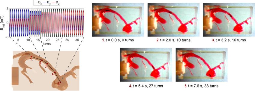
The aneurysm phantom. A patient-representative 3D-printed model of the right middle cerebral artery
was produced, which shows an aneurysm with maximum diameters of 7.24 mm, 5.37 mm and 6.12 mm in each
spatial direction, respectively. The data was acquired by using a 3D rotational angiography scan with a slice
thickness of 0.238 mm (see Fig. 2). More detailed information on the data acquisition can be found in “Materials
and methods”.
Tracking accuracy for the micro‑robot. To measure the accuracy for a later tracking of the micro-robot,
it was attached to a sample holder and images of 27 spatial positions were acquired. Details can be found in
“Materials and methods”. The visualization of the micro-robot as well as the center-of-mass calculations of the
images can be seen in Fig. 3. From these measurements it can be stated that the micro-robot can be tracked with
an average accuracy of 0.68 mm with a standard deviation of 0.35 mm, which corresponds to less than the voxel
size (2 × 2 × 1 mm3) in the experiments carried out. A maximum deviation between the center-of-mass calcula-
tion and the actual position of the micro-robot was found to be 1.5 mm.
Navigation of the → micro‑robot.
− A magnetic− →object carrying a magnetic moment − →
m experiences a torque
of the form − τ = B ×−
→ →
m inside a magnetic field B , i.e. the magnetic moment aligns with the magnetic field
vector. For navigating the micro-robot on an intended pathway, a homogeneous magnetic field with a rotating
field vector is needed. The micro-robot follows the rotation and performs a forward velocity due to its shape.
The field vector is rotated in the plane perpendicular to the intended direction of movement. Such a magnetic
field can be generated with an MPI scanner by using the focus fields, which are typically used to shift the field of
view (FOV) in space. The focus field consists of three coils, each generating a homogeneous magnetic field with
a magnetic field vector orthogonally to each other. By the superposition of the three focus fields in x-, y- and
z-direction, an arbitrary resulting field vector can be generated. When applying sinusoidal currents with a phase
shift of 90° to the focus field coils, a rotating field vector can be generated. Detailed information can be found
Scientific Reports | (2021) 11:14082 | https://doi.org/10.1038/s41598-021-93323-4 2
Vol:.(1234567890)
www.nature.com/scientificreports/
Figure 1. The magnetic micro-robot. (A) The CAD model of the micro-robot. The geometry is inspired by
vertical axis wind turbines and is called helical Savonius shape. (B) The micro-robot is 3D-printed using a
stereolithographic printing procedure. (C) It is coated with SPIONs for the visualization with MPI. The tip
consists of NdFeB particles, introducing a magnetic moment for MA. (D) The magnetization curve of the
micro-robot, acquired with a VSM showing a superposition of a paramagnetic and a ferromagnetic behavior.
(E) The odd harmonics of the amplitude spectrum, acquired with a magnetic particle spectrometer with an
excitation frequency of 25 kHz and an amplitude of 20 mT.
in “Materials and methods” and a schematic drawing is shown in Fig. 8. The pathway through the aneurysm
phantom is discretized into four straight path segments, which seemed to approximate the actual path curvature
sufficiently, and converted into corresponding magnetic field strengths for the focus field coils (see Fig. 4). The
number of turns for each segment was calculated based on the experimentally observed velocity, which was
found to be suitable to cover the path length. Since the used MPI scanner allows to read in discretized values of
the focus fields, the calculated field sequences are discretized into 20 steps per rotation. The video, showing the
micro-robot moving through the middle cerebral artery into the aneurysm of the phantom can be found in the
Supplementary Material, selected frames of the video are displayed in Fig. 4.
Tomographic visualization and navigation. As in clinical procedure, an angiogram of the aneurysm
phantom is conducted at first. Here, the angiogram is recorded using MPI and a homogeneous tracer distribu-
tion filled into the phantom. Parameters for image acquisition, reconstruction and visualization are given in
“Materials and methods”.
For tracking the micro-robot during MA, sequential images were acquired at the beginning and after each
manipulation step resulting into five recordings (see parameters in “Materials and methods”). It has to be noted,
that the aneurysm phantom was not filled with tracer material for MA but with the same glycerol–water mixture
as for the navigation experiments. The reconstruction results of the micro-robot inside the aneurysm phantom
can be seen in Fig. 5. An animated view can be found in the Supplementary Material. The reconstructed micro-
robot is superposed with the reconstructed image of the angiogram (first row). Furthermore, the calculated
center of mass of the micro-robot is superposed with the angiogram (second row) for demonstrating the tracking
ability of the micro-robot.
Hyperthermia of micro‑robot. A fluid, which contains magnetic nanoparticles, can be heated by apply-
ing fast alternating magnetic fields. This technique is widely used for therapeutic reason to locally heat abnormal
tissue28. Since heat facilitates the clotting of blood it is aimed at increasing the temperature inside the aneurysm.
A temperature increase of about 4 K was observed in the sample chamber within a heating time of 3 min, before
the sample cooled down when switching off the field. The measurement results can be seen in Fig. 6.
Scientific Reports | (2021) 11:14082 | https://doi.org/10.1038/s41598-021-93323-4 3
Vol.:(0123456789)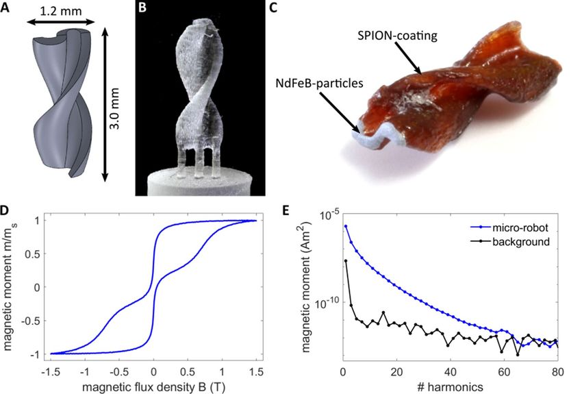
www.nature.com/scientificreports/

                                            Figure 2.  Aneurysm phantom. The aneurysm is located at the right middle cerebral artery and indicated by the
                                            blue arrow. (A) The patient’s CT image. (B) One image from patient’s 3D rotational angiography images. (C) 3D
                                            rendered representation of the patient’s rotational angiography. (D) For further processing, the aneurysm and
                                            the access route were isolated as shown by the coronary oblique view. (E) The 3D-printed phantom is enclosed
                                            by a cuboid and can be attached to the sample holder of the MPI scanner by a plug-in connection.

                                            Figure 3.  Tracking accuracy for the micro-robot with MPI. (A) Robot movement for the acquisition of
                                            27 spatial positions of the micro-robot. (B) Visualization of the micro-robot exemplarily at three different
                                            positions. Projection images for each spatial direction are shown. (C) The center-of-mass (CoM) calculation for
                                            27 different positions, compared to the actual position of the micro-robot. A mean deviation of 0.68 mm and
                                            maximum deviation of 1.5 mm between the CoMs and the actual position were found.

          Scientific Reports |   (2021) 11:14082 |              https://doi.org/10.1038/s41598-021-93323-4                                                4

Vol:.(1234567890)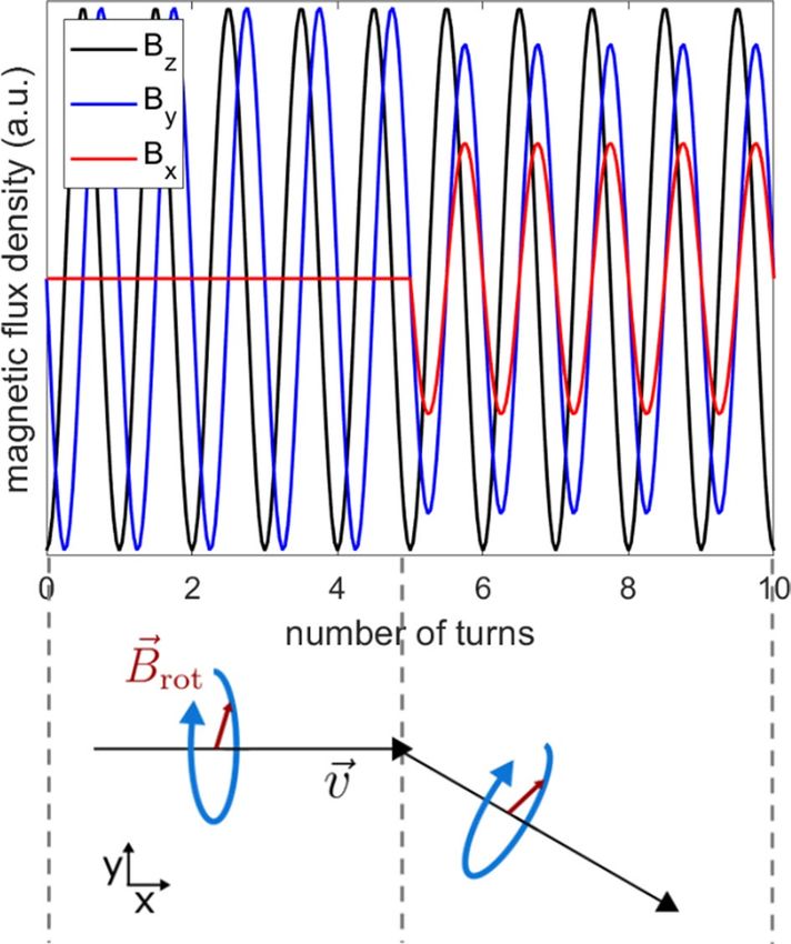
www.nature.com/scientificreports/
Figure 4. Navigation of the micro-robot with an MPI scanner through the aneurysm phantom. The path
through the aneurysm phantom is approximated by four straight path segments by using the CAD model.
According to the path segments the focus fields are calculated, such that the field vector rotates in the plane
perpendicular to the path segment. A rotation frequency of 5 Hz and an amplitude of 3 mT is applied. The video
stills show the resulting movement of the micro-robot through the human phantom, which was filled with a red
stained glycerol-water mixture to mimic the viscosity of blood. The measurement is conducted inside an MPI
scanner. The video can be found in the Supplementary Material.
Figure 5. MPI images of the micro-robot inside the aneurysm phantom. Superposition of the reconstructed
and registered images of the angiogram and the micro-robot at five positions along the pathway through the
middle cerebral artery (see Fig. 4 for path segments). In the bottom row, the calculated center of mass of the
micro-robot is visualized.
Discussion
In this work we show the potential of MPI for the steering and visualization of a micro-robot with the perspec-
tive of cerebral aneurysm coiling. Our previous work already showed the feasibility of a 2D visualization and
actuation of a coated swimmer with MPI4. Here, we improved the manufacturing process of the micro-robot in
terms of smaller size (because another 3D-printing technique was used) sufficient imaging signal even though a
smaller object provides less surface for coating and larger magnetic moment (because another coating procedure
and different particles were used). The larger magnetic moment can be assumed as a much lower field strength
led to a rotation of the micro-robot (here 3 mT, in4 18 mT). Further, the new opportunity of path planning
allowed the steering through a model of a real vascular structure. The investigation of the tracking accuracy,
the 3D visualization with the overlay of an angiogram as well as the ability to conduct hyperthermia show the
potential for future medical applications. In the last decade, numerous studies have proven the potential of MPI
guided cardiovascular interventions. For example, a balloon-angioplasty was monitored in real time with MPI29.
Furthermore, safety measurements of endovascular s tents30 and catheters/guidewires31 were conducted. Flow
measurements of aneurysms were given32 in a comparison study with digital subtraction angiography (DSA) and
magnetic resonance angiography (MRA). Furthermore, the detection of ischemic stroke and cerebral bleeding in
rodents is possible with MPI33,34. Thus, in principle MPI seems to be eligible to conduct monitoring of aneurysm
coiling. Especially due to the absence of nephrotoxic contrast agents and ionizing radiation for the acquisition
of the angiogram, MPI is a very promising alternative to the clinically established DSA. Clinical MPI scanners
Scientific Reports | (2021) 11:14082 | https://doi.org/10.1038/s41598-021-93323-4 5
Vol.:(0123456789)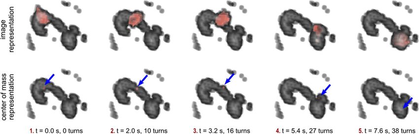
www.nature.com/scientificreports/
Figure 6. Hyperthermia measurement. (A) A schematic drawing of the hyperthermia setup. The micro-
robot was covered with water inside an Eppendorf tube. An oscillating magnetic field of 30 mT amplitude and
557.5 kHz frequency was applied for 3 min. (B) The temperature of the water, surrounding the micro-robot is
displayed.
are not available yet, but a first human sized MPI scanner for brain application was p resented35. This scanner
already features a FOV which would be large enough to image the cerebral vessels of a single hemisphere. So far,
perfusion imaging was sufficiently performed with this scanner utilizing in-vitro flow models.
The used phantom is a representation of a patient’s anatomy. However, the used material and the conditions
are not directly comparable. The phantom was filled with a glycerin-water mixture and the experiments were
conducted without flow. In a subsequent in-vivo procedure it could be possible to stop the blood flow by means
of a balloon catheter to achieve significantly improved control of the microrobot, which should both improve
the accuracy of the procedure and increase patient safety by reducing embolic complications. Further, it needs
to be mentioned that the navigation of the here presented micro-robot is limited in terms of uphill and downhill
navigation. It can overcome some obstacles and smooth ascents, but for navigating against the gravity a micro-
robot of larger buoyancy would be needed or much larger rotation frequencies need to be applied.
The micro-robot may get washed away by the blood flow causing embolic complications as soon as it has
reached the aneurysm and the rotating magnetic fields are turned off. To hold the micro-robot in its designated
position until a sufficient thrombosis of the aneurysm occurs it is possible to switch on the MPI scanner’s gradient
field. It induces a magnetic gradient field, which applies a force and can therefore hold the micro-robot inside the
aneurysm, where it remains. One might also think of the development of a micro-robot carrying a coil, which is
made off a micro platinum wire and can be detached as soon as a proper placement is achieved.
The acquisition of an angiogram and the tracking of the micro-robot are feasible with a satisfying accuracy of
less than 1 mm, which is reasonable for the intended application as the middle cerebral artery diameter in humans
is ~ 2.5 mm36. Furthermore, the achieved imaging accuracy is in the range of the spatial resolution of MRA, but
less than DSA37. If necessary, the tracking accuracy could be further improved by using a gradiometric receive
coil38. For the investigation of the accuracy and reliability of the steering process a systematic study inside dedi-
cated phantoms and under in-vivo conditions need to be conducted in future. In-vivo, a bolus of SPIONs would
be administered for the acquisition of an angiogram. For a real-time tracking the sequences between imaging
and actuation need to be altered much faster, which is a constraint of the used MPI scanner. Nevertheless, the
perspective of this approach should be a closed loop control of the micro-robot.
The therapeutic effect of aneurysm coiling is achieved by cutting off the blood supply from the carrier ves-
sel into the aneurysmal lumen by filling the aneurysm with embolization coils, whereby more than one coil is
usually required for complete aneurysm occlusion. In our study we used a single micro-robot to illustrate the
potential for aneurysm coiling, where the aneurysm phantom would have required multiple conventional coils
using standard endovascular treatment. To achieve complete aneurysm occlusion in this case, several micro-
robots would have to be used and ideally functional coating material should be applied. The use of a c oating39
or 3D-printing m aterial40 that swells in liquid surrounding could be an option or a thrombogenic coating of
the micro-robot could be an approach to improve the embolization effect. The feasibility of the micro-robot to
conduct hyperthermia opens the opportunity to apply heat to the surrounding of the micro-robot as soon as
it has reached the aneurysm to induce blood coagulation f aster41. Local temperatures of 42 °C are n ecessary9,
which are potentially applicable with the micro-robot since a temperature difference of 4 °C was already achieved
after 3 min of heating. In relation to a core body temperature of 38 °C the measured temperature increase thus
should be sufficient to induce blood coagulation. Furthermore, the heating of the micro-robot could be used
as a trigger for the release of a thrombogenic drug coating to ensure the embolizing effect of the s wimmer42,43.
However, heat perfusion needs to be considered for in-vivo treatments and the nanoparticles used for the coating
could be optimized for the induction of heat. It has been shown previously that it is possible to monitor the heat
transfer with M PI44–46. Recently, a hyperthermia insert has been presented, which can be attached to the used
MPI scanner and allows the alternation of heating and visualization in one m achine47. Hence, the here presented
study is pointing the way towards MA, hyperthermia and visualization with MPI.
Scientific Reports | (2021) 11:14082 | https://doi.org/10.1038/s41598-021-93323-4 6
Vol:.(1234567890)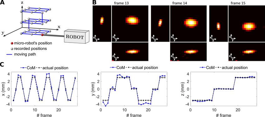
www.nature.com/scientificreports/
There are some limitations of our work which should be addressed: the overall biocompatibility of the micro-
robot has not been investigated and was not in the focus within the presented study, the used material NdFeB and
the impregnating agent of the coating are non-biocompatible ingredients. Further, studies need to be conducted
which show the effectiveness of the micro-robot compared to nowadays used coiling procedures. Especially, the
use of multiple micro-robots should be investigated in future. Furthermore, in vivo studies are needed to prove
the introduced concept under more realistic conditions. Especially the effect of the micro-robot on the wall of the
vessel, where it is moving through, as well as on the aneurysm should be investigated in detail. In addition, the
influence of the blood flow and the feasibility of balloon induced hemostasis should be investigated. In this study
we focused on the investigation of the interaction of the micro-robot with a rotating magnetic field, its steer-
ability through an anatomic vessel structure and the accuracy of localizing the micro-robot’s position with MPI.
Conclusion
A magnetic micro-robot was developed, which can be navigated by rotating focus fields of an MPI scanner
through the anatomy of a human middle cerebral artery towards an aneurysm. The aim of using the micro-robot
as an untethered embolization device was presented using a human aneurysm phantom, which was additively
manufactured from patient’s anatomy. A magnetic coating of the 3D printed micro-robot was developed, to
induce magnetic properties for actuation and visualization with MPI. The micro-robot’s location can be tracked
accurately with a mean deviation of 0.7 mm using a center of mass calculation. For steering the micro-robot into
the aneurysm, the intended pathway was discretized into four path segments and the corresponding magnetic
fields were programmed and applied with a preclinical MPI scanner. The micro-robot was successfully maneu-
vered on the intended pathway into the aneurysm. An angiogram of the phantom, which was filled with tracer
material, was acquired with MPI, showing the middle cerebral artery and the aneurysm. Sequential images were
acquired of the micro-robot, which have been superposed with the angiogram showing the stepwise movement
using MPI. The presented phantom study opens a new idea for cerebral aneurysm coiling with a magnetic micro-
robot, conducted and monitored by an MPI scanner.
Materials and methods
Manufacturing and coating of the magnetic micro‑robot. The SPIONs for the coating of the micro-
robots were produced by the coprecipitation m ethod48. The solution had an iron content of 0.3 mol/l. 1 ml of
the particle solution was mixed with 0.5 ml of an impregnating agent (Nanoseal 180 W, JELN Imprägnierung
GmbH, Schwalmtal, Germany). A little basin with an inner volume of (26 × 6 × 7) mm3 = 1.1 ml, was filled with
the SPION-impregnating agent suspension. The magnetic micro-robot and the basin were 3D-printed (Form2,
Formlabs Inc., Somerville, USA) with “High Temp Resin” (Formlabs Inc.). Three micro-robots were printed
with three pillars each on top of the basin’s cap. When closing the basin, the micro-robots are dipped into the
SPION-Nanoseal suspension. It was then put into the oven for 100 min at 60 °C. The water of the solution could
evaporate through holes in the cap. Figure 7 illustrates the SPION-coating procedure. Further, NdFeB particles
(5 µm Magnequench, Singapore) were mixed into an acrylic lacquer (Cryl Studio, Lukas, Nürnberg, Germany)
with 20 wt%. The tip of the micro-robot was then painted with the NdFeB-lacquer. The micro-robot was imme-
diately positioned onto the surface of a permanent NdFeB magnet during drying to align the magnetic moments
of the particles.
Characterizing the micro‑robot’s magnetic behavior. The magnetic behavior was analyzed with a
vibrating sample magnetometer (8607 VSM System, Lake Shore Cryotronics, Inc., Westerville, Ohio, USA). A
magnetic field of up to 1.5 T was applied. The dynamic behavior was measured with a magnetic particle spec-
trometer, featuring a one-dimensional excitation of 25 kHz and a field amplitude of 20 mT with a spectral resolu-
tion of 2.5 kHz49. The odd-harmonics of the amplitude spectrum are displayed in Fig. 1E, which is the Fourier
transform of the time dependent signal induced by the SPIONs’ nonlinear change of magnetization.
The aneurysm phantom. The 3D clinical rotational angiography data was acquired using an angiography
system (Allura Xper FD 20/20, Philips Healthcare, Best, Netherlands) with the following acquisition parameters:
5 s acquisition time, 220° rotation, 150 individual images at a frame rate of 30/s, (15 × 48) cm2 detector FOV
with a 512 × 512 pixel acquisition matrix. The images were reconstructed with a soft tissue kernel of isotropic
voxel size (edge length 0.238 mm).
Segmentation was performed with Analyze Pro 1.0 (AnalyzeDirect, Overland Park, Kansas, USA), while a
semi-automated approach using a region growth algorithm was used. For this purpose, seed areas were defined
at different points in the vessels. Small perforator arteries were removed if the diameter was smaller than 0.1 mm.
The segmented anatomy was converted into stereolithography (.stl) format. A rectangular box with a size of
(36.5 × 13.1 × 22.2) mm3 was designed to enclose the target vessels of the anatomy and an adapter for the sample
holder of the MPI scanner was attached to the model. Printing was performed on a stereolithography printer
(Form2, Formlabs Inc.) using a 25 µm layer thickness and clear photopolymer resin (Formlabs Inc.). After the
printing process and post-processing steps, the application of clear coat was p erformed50.
Tracking accuracy for the micro‑robot. With a preclinical MPI scanner (MPI 25/20FF, Bruker BioSpin,
Ettlingen, Germany) a system matrix was acquired at first that enables posterior image reconstruction. Drive
field amplitudes of 12 mT have been applied in x-, y-, and z-direction and a gradient strength of 0.625 T/m in
x- and y-direction and 1.25 T/m in z-direction was set, leading to a drive field FOV of (38.4 × 38.4 × 19.2) mm3.
The FOV has been discretized in steps of 2 mm in x- and y-direction and 1 mm in z-direction, according to
the size of the used point sample, resulting in a system matrix of 21 × 21 × 22 voxels and (42 × 42 × 22) mm3,
Scientific Reports | (2021) 11:14082 | https://doi.org/10.1038/s41598-021-93323-4 7
Vol.:(0123456789)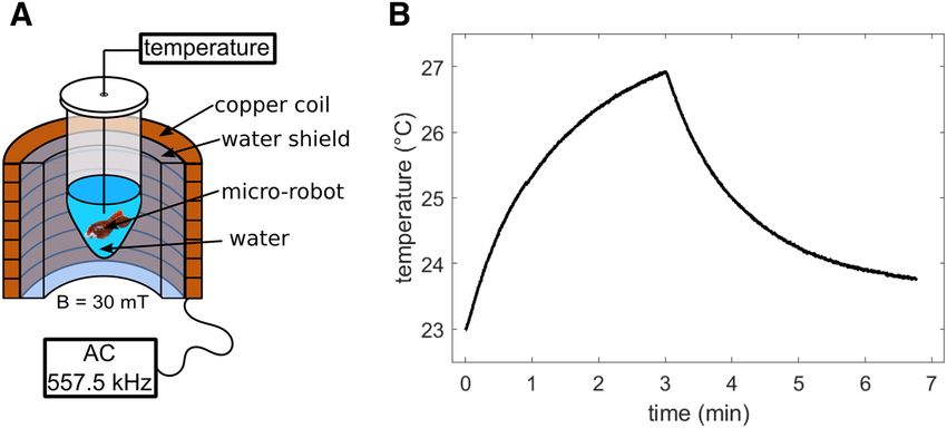
www.nature.com/scientificreports/
Figure 7. Coating procedure of the micro-robot. (A) CAD model of three micro-robots attached to a cap of
a little basin. (B) 3D-printing of the micro-robots and the basin. (C) The tank was then filled with the SPION-
impregnating agent suspension. The tank was closed with the cap, such that the micro-robots are dipped into
the suspension. (D) The evaporation of the water in the suspension formed the SPION coating of the micro-
robot. Afterwards the swimmers are being detached from the cap and the tip is painted with a NdFeB containing
lacquer, as can be seen in Fig. 1.
respectively. This way, an overscan of the system matrix was performed, such that the resulting FOV is larger
OV51. A measurement
than the drive field FOV to avoid potential artifacts from particles outside the drive field F
sample of 4 µl (liquid volume) of SPION-Nanoseal coating was dried to get the same properties as for the micro-
robot’s coating. The receive signal has been averaged 50 times.
The micro-robot (see “Manufacturing and coating of the magnetic micro-robot”) has been attached to a
sample holder, which can be driven precisely by a robot within the scanner bore. MPI measurements of the
micro-robot have been taken at 27 different spatial positions using a 3 × 3 × 3 pattern with a spacing of 3 mm.
The same drive field amplitudes and gradient strength as for the system matrix measurement were applied. The
receive signal has been averaged 500 times.
Image reconstruction for the 27 spatial positions was performed using frequency components of the system
matrix ≥ 80 kHz that feature SNR values above 3. An unregularized Kaczmarz algorithm with one iteration has
been used. An intensity value threshold of 40% of the maximum value has been applied prior to visualization and
center of mass calculation. Three of the reconstructed images are exemplarily displayed in Fig. 3A. The center
of mass (CoM) of all reconstructed images was calculated using
n
ri ) · �ri
i=1 I(�
�rCoM = n
i=1 ri )
I(�
with −
→r the spatial position, I the intensity value between 0 and 1 and n the number of voxels in the 3D image. The
calculated CoMs are visualized in Fig. 3B. The actual position of the micro-robot may differ from the position
calibrated by the system matrix due to e.g. misplacement of the object in the sample holder. Therefore, the center
position of the micro-robot was calibrated for each spatial direction independently by using the reconstructed
images corresponding to a spatial position of the micro-robot in the zero plane of x-, y- and z-direction. These
calibrated actual positions have been averaged and were then subtracted from all the calculated CoMs as a
global offset. The accuracy was calculated as the mean euclidean distance between the evaluated CoMs and the
calibrated actual positions of the micro-robot
N −
||→
r CoM − − →
i i
r actual ||2
accuracy = i=1
N
with N = 27 the number of frames.
Navigation of the micro‑robot with an MPI scanner. Assuming a direction of movement − →
v , defined
by the azimuth angle φ and the polar angle θ in spherical coordinates, the direction of movement reads:
Scientific Reports | (2021) 11:14082 | https://doi.org/10.1038/s41598-021-93323-4 8
Vol:.(1234567890)www.nature.com/scientificreports/
Figure 8. Magnetic actuation with an MPI scanner by using rotating focus fields. The resulting field vector
−
→
B rot (t) needs to rotate in the plane perpendicular to the direction of movement −
→
v of the micro-robot. Such a
field vector is generated by the superposition of orthogonally generated focus fields of an MPI scanner.
cos φ sin θ
v� = sin φ sin θ .
cos θ
The two vectors, perpendicular to −
→
v , define the plane of rotation for the magnetic field vector:
−sin φ cos φcos θ
B� 1 = Brot cos φ , B � 2 = Brot sin φ cos θ
0 −sin θ
with Brot the amplitude. A rotating field vector with an angular frequency ω has the form:
�
−sin φcos ωt + cos φ cos θ sin ωt Bx
�
B � 1 cos ωt + B
� rot (t) = B � 2 sin ωt = Brot cos φ cos ωt + sin φ cos θ sin ωt = By .
− sin θ sin ωt Bz
The currents, which need to be applied to the three focus field coils of the MPI scanner are proportional to
Bx , By and Bz , respectively. The used MPI scanner (Bruker BioSpin) allows a maximum focus field strength of
18 mT. The application of slow alternating currents to the focus field coils is possible. For a movement of the
micro-robot only in the horizontal plane (θ = 90◦) the rotating magnetic field simplifies to
−sin φ cosωt
� rot (t) = Brot cos φ cos ωt .
B
−sin ωt
A schematic drawing, showing the rotating magnetic field vector dependent on the direction of movement
as well as the corresponding magnetic fields Bx , By and Bz can be found in Fig. 8.
The path segments are chosen from the CAD model of the phantom by placing five points along the middle
cerebral
→artery. From the five points the intended direction of movement is calculated for each path segment
−
giving B rot (t) for four path segments. The number of turns have to be chosen according to the velocity of the
micro-robot, the applied frequency and the path-length. The aneurysm phantom was filled with a red stained
water-glycerol mixture with a mixing ratio of 2:1. The fluid had a viscosity of about 3.5 mPa·s (according to
Cheng et al.52) to better imitate the conditions of blood. The micro-robot was inserted into the phantom and
the openings were sealed. At a frequency of 5 Hz 38 turns in total resulting into an actuation time of 7.6 s were
found to be suitable to cope the pathway with the micro-robot. Each period was discretized into 20 focus field
steps, which can be read in by the MPI scanner. A ramping at the beginning and at the end within 10 focus field
Scientific Reports | (2021) 11:14082 | https://doi.org/10.1038/s41598-021-93323-4 9
Vol.:(0123456789)www.nature.com/scientificreports/
steps have been added to avoid large amplitude changes. That gives a total of 780 focus field steps. The ramping
time between each focus field step was set to 10 ms, resulting into a rotation frequency of 5 Hz.
Tomographic visualization and navigation with an MPI scanner. The angiogram and sequential
images of the micro-robot have been acquired using the same preclinical MPI scanner as above (see “Tracking
accuracy of the micro-robot”). The drive field amplitudes, gradient strength and system matrix shape have been
constant throughout this work.
The aneurysm phantom was filled with tracer material (Resovist, 0.5 mmol Fe/ml, I’rom Pharmaceuticals,
Tokyo, Japan) with a dilution of 1:100 for acquiring the angiogram. The angiogram was acquired within 15 s,
such that the receive signals have been averaged 700 times. For image reconstruction a system matrix with a
sample volume of 4 µl and a dilution of 1:3 of the same tracer material was recorded. Image reconstruction has
been performed using frequency components of the system matrix ≥ 65 kHz that feature SNR values above 10.
A Kaczmarz algorithm with 10 iterations and a Tikhonov-regularization with a regularization factor of 10–3 have
been used. An intensity value threshold of 10% has been applied prior to visualization.
For visualizing the micro-robot within the aneurysm phantom during MA, the aneurysm phantom has
been carefully rinsed and filled with the same water-glycerol mixture as for the navigation experiments. Then,
the micro-robot has been inserted in the aneurysm phantom (see Fig. 4, first position). Since the micro-robot’s
movement is approximated as a movement in the plane, the aneurysm phantom had to be rotated a little in
comparison to the angiogram measurement. During MA, an MPI measurement was performed at the beginning
and after each manipulation step. The measurements have been reconstructed using the system matrix described
above (see “Tracking accuracy of the micro-robot”). Frequency components featuring minimum SNR values of
10 have been selected for reconstruction. A Kaczmarz algorithm with one iteration and a Tikhonov regulariza-
tion with a regularization factor of 0.1 have been used. For visualization and CoM calculation, an intensity value
threshold of 50% has been applied.
As stated above, the aneurysm phantom had to be rotated before MA. Therefore, the reconstructed image
of the aneurysm phantom is rotated against the reconstructed images of the micro-robot within the aneurysm
phantom. A registration is carried out by rotating the reconstructed 3D volume of the aneurysm phantom before
MA. The superposition of the (rotated) angiogram and the reconstructed images of the micro-robot are visual-
ized in Fig. 5 (top). Furthermore, the CoM of the reconstructed images of the micro-robot are superposed to
the angiogram in Fig. 5 (bottom).
Hyperthermia of micro‑robot. The micro-robot is placed inside an Eppendorf tube with 16 µl water, such
that the micro-robot is completely covered with water. Hyperthermia measurements are conducted with a self-
built setup featuring a magnetic field of 557.5 kHz with 30 mT amplitude and a water shield absorbing the heat
of the excitation coil. Additional polystyrene insulation separates the sample chamber from the water shield. A
fiber optical temperature sensor measured the temperature of the water surrounding the micro-robot and two
additional sensors measure the temperature of the excitation coil and the interface between the water shield and
the insulation.
Ethical approval and informed consent. All methods were carried out in accordance with relevant
guidelines and regulations. The use of the clinical data was approved by the institutional review board of the
University of Lübeck (registry number 20-121a) in this single-center retrospective study with waived individual
consent. Informed consent was waived by the same ethics committee that approved the study.
Received: 14 December 2020; Accepted: 11 June 2021
References
1. Rey, J. et al. Feasibility of stomach exploration with a guided capsule endoscope. Endoscopy 42, 541–545 (2010).
2. Munoz, F., Alici, G. & Li, W. A review of drug delivery systems for capsule endoscopy. Adv. Drug Deliv. Rev. 71, 77–85 (2014).
3. Sitti, M. et al. Biomedical applications of untethered mobile milli/microrobots. Proc. IEEE 103, 205–224 (2015).
4. Bakenecker, A. C. et al. Actuation and visualization of a magnetically coated swimmer with magnetic particle imaging. J. Magn.
Magn. Mater. 473, 495–500 (2019).
5. Lee, S. et al. Fabrication and characterization of a magnetic drilling actuator for navigation in a three-dimensional phantom vascular
network. Sci. Rep. 8, 1–10 (2018).
6. Ghosh, A. & Fischer, P. Controlled propulsion of artificial magnetic nanostructured propellers. Nano Lett. 9, 2243–2245 (2009).
7. Nelson, B. J., Kaliakatsos, I. K. & Abbott, J. J. Microrobots for minimally invasive medicine. Annu. Rev. Biomed. Eng. 12, 55–85
(2010).
8. Tottori, S. et al. Magnetic helical micromachines: Fabrication, controlled swimming, and cargo transport. Adv. Mater. 24, 811–816
(2012).
9. Ceylan, H., Yasa, I. C., Kilic, U., Hu, W. & Sitti, M. Translational prospects of untethered medical microrobots. Prog. Biomed. Eng.
1, 012002 (2019).
10. Dogangil, G. et al. Toward targeted retinal drug delivery with wireless magnetic microrobots. In IEEE/RSJ International Conference
on Intelligent Robots and Systems (2008).
11. Wu, Z. et al. A swarm of slippery micropropellers penetrates the vitreous body of the eye. Sci. Adv. 4, 4388 (2018).
12. Medina-Sánchez, M. & Schmidt, O. G. Medical microbots need better imaging and control. Nature 545, 406–408 (2017).
13. Pané, S. et al. Imaging technologies for biomedical micro-and nanoswimmers. Adv. Mater. Technol. 4, 1800575 (2019).
14. Gleich, B. & Weizenecker, J. Tomographic imaging using the nonlinear response of magnetic particles. Nature 435, 1214–1217
(2005).
Scientific Reports | (2021) 11:14082 | https://doi.org/10.1038/s41598-021-93323-4 10
Vol:.(1234567890)www.nature.com/scientificreports/
15. Bakenecker, A. C. et al. Magnetic particle imaging in vascular medicine. Innov. Surg. Sci. 3, 179–192 (2018).
16. Wu, L. C. et al. A review of magnetic particle imaging and perspectives on neuroimaging. Am. J. Neuroradiol. 40, 206–212 (2019).
17. Weizenecker, J., Gleich, B., Rahmer, J., Dahnke, H. & Borgert, J. Three-dimensional real-time in vivo magnetic particle imaging.
Phys. Med. Biol. 54, L1–L10 (2009).
18. Haegele, J. et al. Magnetic particle imaging: Visualization of instruments for cardiovascular intervention. Radiology 265, 933–938
(2012).
19. Nothnagel, N. et al. Steering of magnetic devices with a magnetic particle imaging system. IEEE Trans. Biomed. Eng. 63, 2286–2293
(2016).
20. Rahmer, J., Wirtz, D., Bontus, C., Borgert, J. & Gleich, B. Interactive magnetic catheter steering with 3-D real-time feedback using
multi-color magnetic particle imaging. IEEE Trans. Med. Imaging 36(7), 1449–1456 (2017).
21. Le, T.-A., Zhang, X., Hoshiar, A. K. & Yoon, J. Real-time two-dimensional magnetic particle imaging for electromagnetic naviga-
tion in targeted drug delivery. Sensors 17, 2050 (2017).
22. Griese, F. et al. Simultaneous magnetic particle imaging and navigation of large superparamagnetic nanoparticles in bifurcation
flow experiments. J. Magn. Magn. Mater. 498, 166206 (2020).
23. Rahmer, J., Stehning, C. & Gleich, B. Spatially selective remote magnetic actuation of identical helical micromachines. Sci. Robot.
2, 2845 (2017).
24. Bakenecker, A. C., von Gladiss, A., Friedrich, T. & Buzug, T. M. 3D-printing with incorporated iron particles for magnetic actua-
tion and MPI. Int. J. Magn. Particle Imaging 5, 1–10 (2020).
25. Chalouhi, N., Hoh, B. L. & Hasan, D. Review of cerebral aneurysm formation, growth, and rupture. Stroke 44, 3613–3622 (2013).
26. Morita, A. The natural course of unruptured cerebral aneurysms in a Japanese cohort. N. Engl. J. Med. 366, 2474–2482 (2012).
27. Savonius, S. The Wing-Rotor: In Theory and Practise (Savonius und Co., 1926).
28. Kozissnik, B., Bohorquez, A. C., Dobson, J. & Rinaldi, C. Magnetic fluid hyperthermia: Advances, challenges, and opportunity.
Int. J. Hyperth. 29, 706–714 (2013).
29. Herz, S. et al. Magnetic particle imaging guided real-time percutaneous transluminal angioplasty in a phantom model. Cardiovasc.
Intervent. Radiol. 41, 1100–1105 (2018).
30. Wegner, F. et al. First heating measurements of endovascular stents in magnetic particle imaging. Phys. Med. Biol. 63, 045005
(2018).
31. Duschka, R. et al. Safety measurements for heating of instruments for cardiovascular interventions in magnetic particle imaging
(MPI): First experiences. J. Healthc. Eng. 5, 79–94 (2014).
32. Sedlacik, J. et al. Magnetic particle imaging for high temporal resolution assessment of aneurysm hemodynamics. PLoS ONE 11,
e0160097 (2016).
33. Ludewig, P. et al. Magnetic particle imaging for real-time perfusion imaging in acute stroke. ACS Nano 11, 10480–10488 (2017).
34. Orendorff, R. et al. First in vivo traumatic brain injury imaging via magnetic particle imaging. Phys. Med. Biol. 62, 3501–3509
(2017).
35. Graeser, M. et al. Human-sized magnetic particle imaging for brain applications. Nat. Commun. 10, 1–9 (2019).
36. Serrador, J. M., Picot, P. A., Rutt, B. K., Shoemaker, J. K. & Bondar, R. L. MRI measures of middle cerebral artery diameter in
conscious humans during simulated orthostasis. Stroke 31, 1672–1678 (2000).
37. Guimaraes, M., Schönholz, C., Uflacker, R. & Huda, W. Vascular imaging and radiation safety. in Comprehensive Vascular and
Endovascular Surgery, 73–116 (Elsevier, 2009).
38. Graeser, M. et al. Towards picogram detection of superparamagnetic iron-oxide particles using a gradiometric receive coil. Sci.
Rep. 7, 7 (2017).
39. Cloft, H. J. hydrocoil for endovascular aneurysm occlusion (HEAL) study: Periprocedural results. AJNR Am. J. Neuroradiol. 27(2),
289–292 (2006).
40. Wirth, D. M. et al. Highly expandable foam for lithographic 3D printing. ACS Appl. Mater. Interfaces. 12, 19033–19043 (2020).
41. Cohen, O., Zhao, M., Nevo, E. & Ackerman, J. L. MR coagulation: A Novel minimally invasive approach to aneurysm repair. J.
Vasc. Interv. Radiol. 28, 1592–1598 (2017).
42. Lv, F. et al. Fabrication of step-by-step drug release system both sensitive to magnetic field and temperature based on layered double
hydroxides and PNIPAM. Nanotechnology 30, 055103 (2018).
43. Zhu, X., Li, J., Peng, P., Nassab, N. H. & Smith, B. R. Quantitative drug release monitoring in tumors of living subjects by magnetic
particle imaging nanocomposite. Nano Lett. 19, 6725–6733 (2019).
44. Dhavalikar, R. & Rinaldi, C. Theoretical predictions for spatially-focused heating of magnetic nanoparticles guided by magnetic
particle imaging field gradients. J. Magn. Magn. Mater. 419, 267–273 (2016).
45. Hensley, D. et al. Combining magnetic particle imaging and magnetic fluid hyperthermia in a theranostic platform. Phys. Med.
Biol. 62, 3483–3500 (2017).
46. Stehning, C., Gleich, B. & Rahmer, J. Simultaneous magnetic particle imaging (MPI) and temperature mapping using multi-color
MPI. Int. J. Magn. Particle Imaging 2(2), (2016).
47. Wei, H., Behrends, A., Friedrich, T. & Buzug, T. A heating coil insert for a preclinical MPI scanner. Int. J. Magn. Particle Imaging
6(2), 1 (2020).
48. Gupta, A. K. & Gupta, M. Synthesis and surface engineering of iron oxide nanoparticles for biomedical applications. Biomaterials
26, 3995–4021 (2005).
49. Biederer, S. et al. Magnetization response spectroscopy of superparamagnetic nanoparticles for magnetic particle imaging. J. Phys.
D 42, 205007 (2009).
50. Schwenke, H., Kemmling, A. & Schramm, P. High-precision, patient-specific 3D models of brain aneurysms for therapy planning
and training in interventional neuroradiology. Trans. AMMM 1(1), (2019).
51. Weber, A., Werner, F., Weizenecker, J., Buzug, T. M. & Knopp, T. Artifact free reconstruction with the system matrix approach by
overscanning the field-free-point trajectory in magnetic particle imaging. Phys. Med. Biol. 61, 475–487 (2015).
52. Cheng, N.-S. Formula for the viscosity of a glycerol–water mixture. Ind. Eng. Chem. Res. 47, 3285–3288 (2008).
Acknowledgements
The authors thank Carlos Chinchilla for his support to conduct the numeric simulations on the micro robot’s
velocity and Zuzana Penxova for undertaking the magnetic coating procedure.
Author contributions
A.C.B. developed the micro-robot, programmed and implemented the magnetic field calculation, planned,
performed and evaluated the experiments, visualized the results and wrote the original draft. A.v.G. realized the
sequential image reconstruction including registration and visualization. H.S. developed and built the human
aneurysm phantom. A.v.G. and H.S. edited the manuscript. A.B. and A.C.B. built the table-top actuation setup
and performed the velocity measurements. K.L.B. and A.C.B. realized the magnetic coating. A.N. performed
hyperthermia measurements. T.F. supported the experiments conducted with the MPI scanner. H.S., J.B. and F.W.
Scientific Reports | (2021) 11:14082 | https://doi.org/10.1038/s41598-021-93323-4 11
Vol.:(0123456789)www.nature.com/scientificreports/
contributed to the interpretation of the data and critically revised the manuscript towards the medical application
scenario. F.W. had the initial application idea and contributed to the conception and performance of the experi-
ments. T.M.B. planned, supervised and coordinated the project and was involved in the data interpretation and
the editing of the manuscript. All authors approved the final version of the manuscript.
Funding
Open Access funding enabled and organized by Projekt DEAL. The authors gratefully acknowledge the Fed-
eral Ministry of Education and Research, Germany (BMBF) for funding this project under Grant Numbers
13GW0230B (FMT), 13GW0069A (SAMBA PATI), 01DL17010A (IMAGINE) and 13GW0071D (SKAMPI).
Competing interests
The authors declare no competing interests.
Additional information
Supplementary Information The online version contains supplementary material available at https://doi.org/
10.1038/s41598-021-93323-4.
Correspondence and requests for materials should be addressed to A.C.B. or T.M.B.
Reprints and permissions information is available at www.nature.com/reprints.
Publisher’s note Springer Nature remains neutral with regard to jurisdictional claims in published maps and
institutional affiliations.
Open Access This article is licensed under a Creative Commons Attribution 4.0 International
License, which permits use, sharing, adaptation, distribution and reproduction in any medium or
format, as long as you give appropriate credit to the original author(s) and the source, provide a link to the
Creative Commons licence, and indicate if changes were made. The images or other third party material in this
article are included in the article’s Creative Commons licence, unless indicated otherwise in a credit line to the
material. If material is not included in the article’s Creative Commons licence and your intended use is not
permitted by statutory regulation or exceeds the permitted use, you will need to obtain permission directly from
the copyright holder. To view a copy of this licence, visit http://creativecommons.org/licenses/by/4.0/.
© The Author(s) 2021
Scientific Reports | (2021) 11:14082 | https://doi.org/10.1038/s41598-021-93323-4 12
Vol:.(1234567890)You can also read