Version: 1.3.2 REVISED 05/18/2021 - Please read this manual carefully before using the PuriFi Purification System. Serial Number: ...
←
→
Page content transcription
If your browser does not render page correctly, please read the page content below

Version: 1.3.2
            REVISED 05/18/2021

Please read this manual carefully before using
        the PuriFi Purification System.

Serial Number: __________________________

Installation Date: ________________________

Licensed Installer: _______________________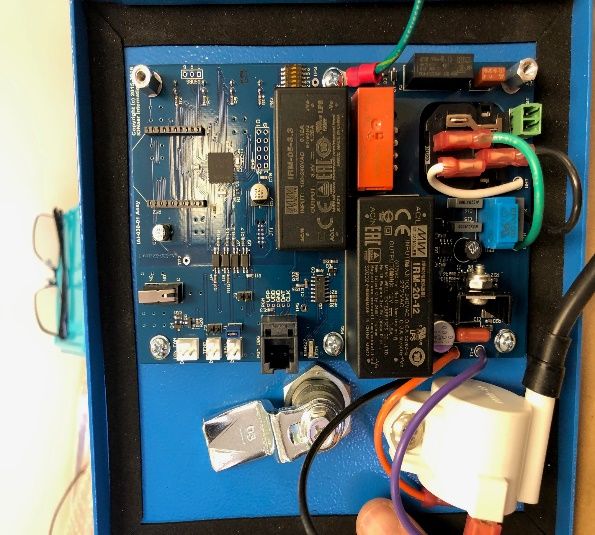
No part of this manual, including the product and peripheral components described in it, may be
reproduced, transmitted, stored in a retrieval system, or translated into any language in any form or by
any means, except documentation kept by the purchaser for backup purposes, without the express
written permission of PuriFi Labs.

Product warranty or service will not be extended if the product is repaired, modified or altered, unless
such repair, modification or alteration is authorized in writing by PuriFi Labs.

PURIFI LABS PROVIDES THIS MANUAL “AS-IS” WITHOUT WARRANTY OF ANY KIND, EITHER EXPRESS OR
IMPLIED, INCLUDING BUT NOT LIMITED TO THE IMPLIED WARRANTIES OR CONDITIONS OF
MERCHANTABILITY OR FITNESS FOR A PARTICULAR PURPOSE.

IN NO EVENT SHALL PURIFI LABS, ITS DIRECTORS, OFFICERS, EMPLOYEES OR DISTRIBUTORS BE LIABLE FOR
ANY INDIRECT, SPECIAL, INCIDENTAL, OR CONSEQUENTIAL DAMAGES (INCLUDING DAMAGES FOR LOSS
OF PROFITS, LOSS OF BUSINESS, LOSS OF USE OR DATA, INTERRUPTION OF BUSINESS, ETC.), EVEN IF
PURIFI LABS HAS BEEN ADVISED OF THE POSSIBILITY OF SUCH DAMAGES ARISING FROM ANY DEFECT OR
ERROR IN THIS MANUAL OR PRODUCT.

SPECIFICATIONS AND INFORMATION CONTAINED IN THIS MANUAL ARE SUBJECT TO CHANGE AT ANY
TIME WITHOUT NOTICE. PURIFI LABS ASSUMES NO RESPONSIBILITY OR LIABILITY FOR ANY ERRORS OR
INACCURACIES THAT MAY APPEAR IN THIS MANUAL, INCLUDING THE PRODUCT DESCRIBED IN IT.

PRODUCT AND CORPORATE NAMES APPEARING IN THE MANUAL MAY OR MAY NOT BE REGISTERED
TRADEMARKS OR COPYRIGHTS OF THEIR RESPECTIVE COMPANIES, AND ARE USED ONLY FOR
IDENTIFICATION OR EXPLANATION TO THE OWNERS’ BENEFIT, WITHOUT INTENT TO INFRINGE.

PuriFi Labs                                     Page 2 of 40                          Phoenix, Arizona, USA
INTRODUCTION

Specifically designed for use in residential, commercial, and industrial applications, the PuriFi™ Generator
is an electronic air purification unit that generates a blend of both negative and positive high-energy ions.
Compact and lightweight, the unit is intended to be installed in duct systems, air handling units, or furnace
plenums – ensuring that the entire occupant space receives beneficial ionization.

The PuriFi Generator introduces an overabundance of natural ions into your system’s airflow. This
patented blend of powerful ions breaks down air and surface contaminants, oxidizing viruses and bacteria,
neutralizing odors and VOCs while driving particulates out of the air.

The proprietary PuriFi O2 Catalyst converts ozone to oxygen, providing the powerful effect of air
purification without the negative byproduct.

This revolutionary air purification technology is a part of PuriFi’s intelligent, responsive air quality
management system. When a change in your indoor air quality is detected, the PuriFi Air Quality Sensor
notifies the PuriFi Smart Hub, and the PuriFi Generator is signaled to respond—all in real-time.
The Smart Hub is compatible with popular digital assistants, including Amazon Alexa and Google Assistant,
as well as standard smart home protocols, including Zigbee, Z-Wave, Lutron®, LAN, and cloud-connected
home automation devices.

Sized for residential homes, a single PuriFi Generator will maintain 2000-2500 square feet of living space.
Your application may require additional units; please consult with your licensed PuriFi contractor to
determine how many units are necessary and which installation method best fits your needs.

Thank you for your investment in the latest air purification technology from PuriFi Labs.
Respectfully,

The PuriFi Labs Team

PuriFi Labs                                      Page 3 of 40                             Phoenix, Arizona, USA
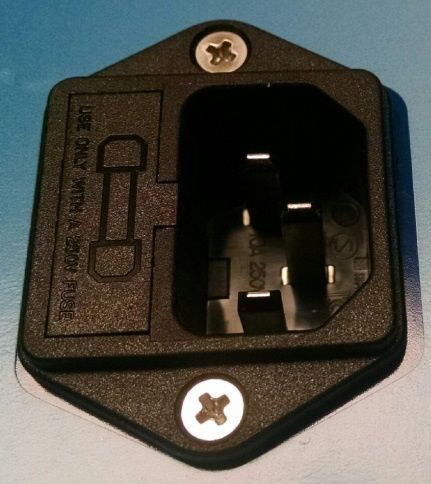
TABLE OF CONTENTS
INTRODUCTION .................................................................................................................................................... 3
PRODUCT SPECIFICATIONS ................................................................................................................................... 6
   APPLICATIONS .................................................................................................................................................. 7
   APPROVALS & CERTIFICATIONS ....................................................................................................................... 7
INSTALLATION – SET UP GUIDE (SOFTWARE & HARDWARE INSTRUCTIONS) ...................................................... 8
   1.      Planning your installation – Site Survey ................................................................................................. 10
   2.      Connecting to and Communicating with the HUB ................................................................................. 11
   3.      Required software and network connections........................................................................................ 11
RESIDENTIAL INSTALLATION INSTRUCTIONS (CONTINUED) ............................................................................................... 13
   4.      Installing the Hardware (Skip to page 19).............................................................................................. 13
   5.      Confirm proper install using the Hubitat. .............................................................................................. 13
   6.      Renaming the PM Sensors and Generators based on the locations ...................................................... 14
COMMERCIAL / CUSTOM INSTALLATION INSTRUCTIONS (CONTINUED) .............................................................................. 14
   4.      Add PuriFi Equipment to the Network................................................................................................... 14
   5.      Installing the Hardware (Skip to page 19).............................................................................................. 16
   6.      Configure the System Settings and Pair Devices.................................................................................... 16
   7.      Tuning the system.................................................................................................................................. 18
   8.      Registering the System .......................................................................................................................... 20
INSTALLATION – MECHANICAL........................................................................................................................... 22
   RECOMMENDED INSTALLATION TOOLS ......................................................................................................... 23
   INSTALLATION SEQUENCE .............................................................................................................................. 24
INSTALLATION – ELECTRICAL.............................................................................................................................. 29
   POWER CONNECTION REQUIREMENTS ......................................................................................................... 30
   HVAC CONNECTION REQUIREMENTS............................................................................................................. 30
OPERATION ........................................................................................................................................................ 31
MAINTENANCE & SERVICE ................................................................................................................................. 32
   FRONT PANEL STATUS LEDs ........................................................................................................................... 32
INSTALLATION – PM PARTICULATE MATTER SENSOR ........................................................................................ 33
TROUBLESHOOTING & FAQ ................................................................................................................................ 34
Factory Reset Generator or Sensor .................................................................................................................... 37
SAFETY INSTRUCTIONS ....................................................................................................................................... 39
WARRANTY INFORMATION ................................................................................................................................ 40

PuriFi Labs                                                               Page 4 of 40                                                  Phoenix, Arizona, USA
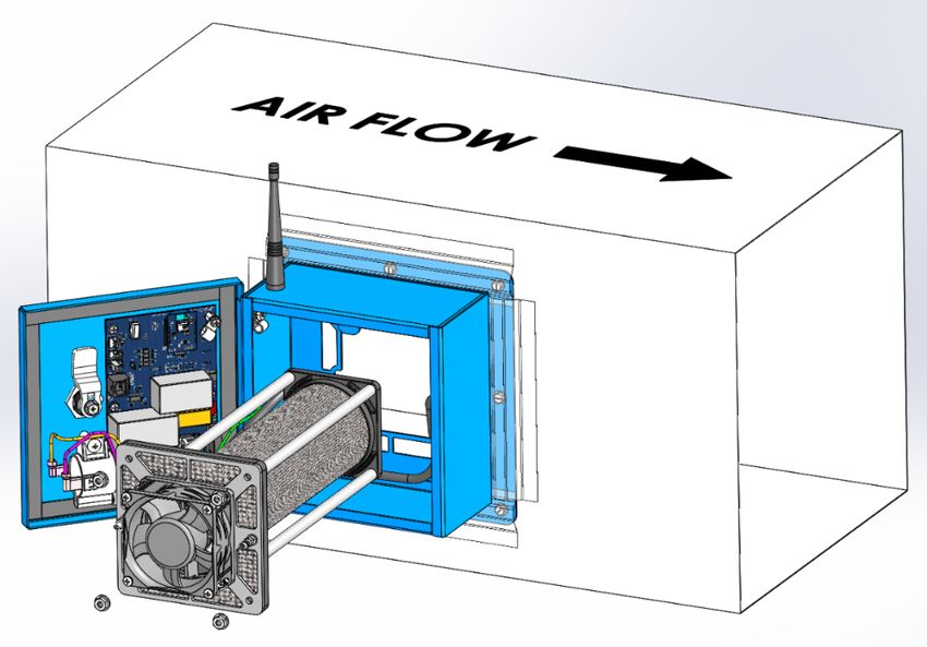
TABLE OF FIGURES
Figure 1 – PuriFi™ Generator Unit Dimensions ............................................................................................ 7
Figure 2 - PuriFi Base System ....................................................................................................................... 8
Figure 3 - Inner “Replaceable Core Module” Assembly Removal .............................................................. 22
Figure 4 – Installation Tools ....................................................................................................................... 23
Figure 5 – Installed PuriFi™ Generator Unit ............................................................................................... 29
Figure 6 - Power Entry Module .................................................................................................................. 30
Figure 7 - HVAC Connections...................................................................................................................... 31

PuriFi Labs                                                         Page 5 of 40                                             Phoenix, Arizona, USA
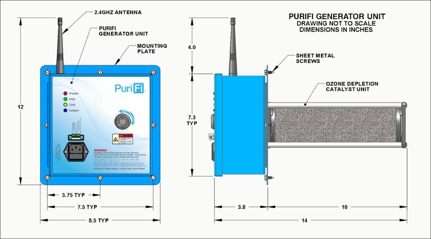
PRODUCT SPECIFICATIONS
Physical Dimensions (Maximum) – H x W x D   12 x 8.5 x 14 inches (305 x 216 x 356 mm) – with Antenna

(Body only)                                 7.3 x 7.5 x 3.8 inches (185 x 191 x 97 mm)

Weight including Mounting Bracket           5.0 pounds (2.3 kg)

Housing Material                            Aluminum 5052

Mounting Bracket Material                   Aluminum 5052

Maximum Ambient Temperature                 200° F (93° C)

Maximum Internal Operating Temperature      150° F (66° C) Safety Shutoff; UL Certified to 180°F (82.2°C)

Input Voltage                               100VAC – 240VAC; 50 or 60 Hz; NEMA 15 Receptacle

Input Current Protection                    2A @ 120VAC, 1A @ 220VAC

Current Draw                                0.10-0.25 Amps @ 120 VAC

Power Consumption (Ionizing Mode)           14-20 Watts

Power Consumption (Ozone Depletion Mode)    3-5 Watts

Effective Area (Volume)                     1,000 - 3500 square feet (~20,000 cubic feet with an 8-foot ceiling)

Air Flow Volume (Min–Max)                   (100CFM – 3000CFM)

Ionization Plasma Tube                      Proprietary (Borosilicate Glass, Stainless Steel, Aluminum)

High Voltage (HV) Transformer Output        5-7kVAC

Safety Features (Access)                    Door Interlock Switch, Special Access Key

Safety Features (Operation)                 Fan Monitoring (RPM), Current Monitoring of HV Transformer

Safety Features (Temperature)               Unit will turn off if internal temperature exceeds 150° F (66° C)

Wireless Capability                         2.4GHz ZigBee 802.15.4 Standard

PuriFi Labs                                     Page 6 of 40                                 Phoenix, Arizona, USA
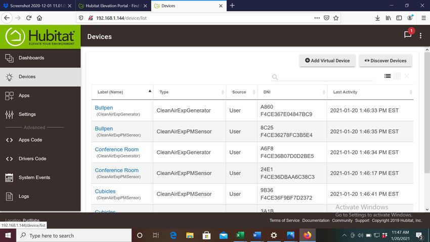
Figure 1 – PuriFi™ Generator Unit Dimensions

APPLICATIONS
   Ø Residential Settings (Homes, Condos, Hotels, Motels)
   Ø Commercial Environments (Small Businesses, Restaurants, Beauty Salons)
   Ø Industrial Locations (Factories, Large Scale Processing Operations)
   Ø Health & Well-Being (Hospitals, Doctor Offices, Therapy Establishments)
   Ø Education & Childcare (Nurseries, Pre-Schools, Schools & Universities)
   Ø Public Health (Bathrooms)
   Ø Public Transportation (Aircraft, Buses, Trains, Taxis, et cetera)
   Ø Agricultural, Farms (Odor Mitigation)

APPROVALS & CERTIFICATIONS
   1. UL STANDARD 1995
   2. UL STANDARD 867
   3. CSA STANDARD C22.2 NO. 236
   4. CSA STANDARD C22.2 NO. 187
   5. FCC COMPLIANCE TO CFR PART 15 SUBPART B FOR CLASS B DIGITAL DEVICE
   6. CE RED EN 301 489-1: 2017 (V2.2.0), RED EN 301 489-17: 2017 (V3.2.0)
   7. CE EN55032 Class B, EN61000-3-2, EN61000-3-3, EN61000-4-2, EN61000-4-3, EN61000-4-4,
      EN61000-4-5, EN61000-4-6, EN61000-4-11

PuriFi Labs                                 Page 7 of 40                       Phoenix, Arizona, USA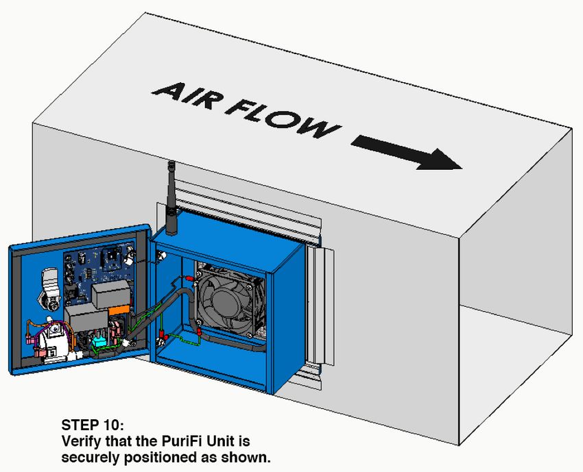
INSTALLATION – SET UP GUIDE (SOFTWARE & HARDWARE INSTRUCTIONS)

      WARNING: This product must be installed by a licensed HVAC contractor.
Failure to do so will void the warranty of the PuriFi™ System.

WARNING: The electrical service to this unit must conform to local, national, and international safety
codes where applicable, and must be carried out by qualified individuals. Make sure that 100-240VAC
50/60Hz is available at the site of installation.

1. Unpackage the PuriFi Generator and verify that all items are present.

                                        Figure 2 - PuriFi Base System

     1.   PuriFi Generator Unit                                    5.   Installation Guide (not pictured)
     2.   Power Cord (110V / 240V as required)                     6.   Hex Nuts (4)
     3.   Antenna – 2.4GHz (Install finger tight)                  7.   PM Particulate Matter Sensor
     4.   Mounting Plate (attach to duct)                          8.   Home Automation “HUB”

NOTE: For best results, pair the RF Radios in the HUB & PM Sensor that will be
associated with their specific Generator before installing the Generator into the
HVAC duct.

PuriFi Labs                                         Page 8 of 40                              Phoenix, Arizona, USA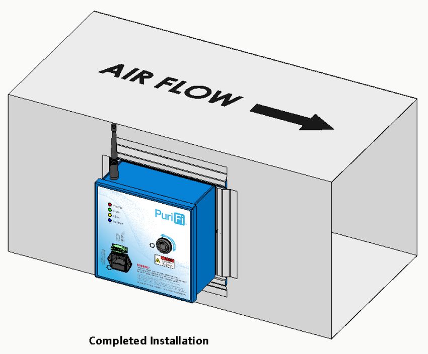
2. Make sure all necessary tools are available for installation (see page 22 below in this document).

3. Select a location in the duct downstream of the Air Handler that provides adequate air flow.
          a. NEVER install unit downstream of anything that produces moisture (e.g. evaporative cooler).
          b. Ensure that duct size is at least 12 x 12 inches where the PuriFi™ Generator is to be mounted.
          c. CAUTION: This product shall not be installed behind a suspended floor/ceiling or a structural
             wall, ceiling, or floor.
          d. CAUTION: This product is suitable for mounting to duct of metallic construction only.
             Installation must be such that the structural integrity of the ducting is not compromised.
4. Make sure that 100-240VAC 50/60Hz is available to the unit (qualified electrician or contractor).
5. Prepare ducting for the Generator unit.
          a. Trace cutout and mark screw locations.
          b. Cut out traced portion using tin snips or other means.
          c. Screw the Mounting Plate to duct using No. 10 sheet metal screws.
6. Run control wires from 4-Position removable connector (front door of Generator) to HVAC fan unit
          a. Option A – the HVAC unit relay output controls PuriFi Generator operation
          b. Option B – PuriFi Generator can control HVAC unit fan.
7. Apply power and verify System operation.
          a. Generator in radio communication and ionizing.
          b. PM Sensor positioned correctly and showing PM Particulate Matter on LCD Display.
          c. HUB unit linking PM Sensor & Generator working properly.
                  i. For localized close-loop control
                  ii. For transmitting IAQ data to the AWS Cloud Repository (Recommended but Optional)
8. Register the systems online at app.purifilabs.com.

PuriFi Labs                                      Page 9 of 40                            Phoenix, Arizona, USA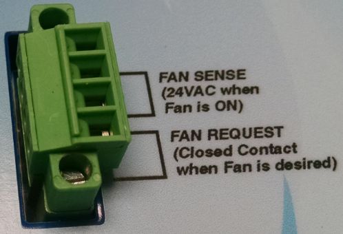
- PLEASE REVIEW THIS GUIDE BEFORE INSTALLATION -

Overview:
This guide will lead through the following steps:
     1. Planning your installation – Site Survey (Site Survey Document- see partner portal)
     2. Required software and network connections
     3. Connecting to and communicating with the HUB
     4. Installing the hardware
     5. Confirm proper install using the Hubitat.
     6. Renaming the PM Sensors and Generators based on the locations
     7. Tuning the system
     8. Registering the System

Appendices:
     1. HUB Placement Tips
     2. How to Build a Solid Zigbee Mesh
     3. Setting up a wired-to-wireless bridge utilizing a GL-iNet mini router

1. Planning your installation – Site Survey
1a: HUB Location: Depending upon how many heating/cooling zones there are, the approach used for
planning where the HUB is located might change.
     •    If there is a single zone used in the residence or office, the HUB should be located within 20-40
          feet of the Generator and/or PM Sensor.
     •    For best results, it is recommended that you locate the HUB in a central location.
The mesh network formed by the PuriFi system can “hop” through Generator or PM Sensor devices to
communicate with other devices on the network. This means that devices normally just need to be within
20-40 feet of another Zigbee RF radio device, not the main HUB.

1b: Sensor Location: PM Sensors are normally placed at a level of 3 feet (1 meter) above ground or higher
on a shelf or wall outlet within the zone of the associated (paired) Generator. For best results, it is
recommended that you:
     •    Avoid areas that would have excessive smoke or grease such as close to a kitchen stove or oven.
     •    Avoid bathrooms (specifically tubs/showers) where steam is likely to be present.
     •    Avoid positioning too low to the ground where dust particle measurements are not truly in the
          desired “breathing zone.”

PuriFi Labs                                     Page 10 of 40                           Phoenix, Arizona, USA
2. Connecting to and Communicating with the HUB
Use the provided network cables to connect the HUB.
To Internet: MUST be To Power: The HUB can
plugged directly into be connected to any
an open LAN port* on USB-compatible power
customer’s modem, source, including the
router, or switch. supplied plug.
*Note: If a hardwired local area network (LAN) connection is difficult to access or forces the HUB to be in
a non-optimum location, consider using a wired-to-wireless bridge as described in Appendix 3. Please
consult with your Licensed Installer.
Wait until the LED on the front of the HUB turns GREEN. This indicates it is in the final stages of powering
up or fully powered up and should be “discoverable.”
3. Required software and network connections
Software - There are two options for software, and both provide similar user interfaces:
• Option A - You can visit the Apple App Store or Google Play Store and download the Hubitat Elevation
app for your mobile device.
• Option B - you can use any laptop, PC, or tablet with a modern browser (Firefox or Chrome
recommended) to access the online portal.
Network - The HUB requires a hardwired connection to the LAN to function properly. This hardwired
setup expects to receive an IP address from a dynamic host configuration protocol (DHCP) Server. For
initial setup, it will need to be able to access the internet for configuration data (pre-configured setups for
PM Sensors, Generators, and Dashboards). In addition, if the mobile app or geofencing is used, internet
service is required to function properly.
The HUB also creates a local radio mesh network (via Zigbee protocol) to communicate between the PuriFi
devices. This is different from the LAN used in the residence or office. In the average residence or small
office, the HUB should maintain connection with equipment regardless of location. If equipment will be
installed more than 50 feet from the HUB, ZigBee routers / repeaters or an additional HUB may be
required.
NOTE: Do not attempt to continue the installation until the local HUB has been discovered as described
below.
PuriFi Labs Page 11 of 40 Phoenix, Arizona, USAMobile App – First make sure that your mobile device is on the same
LAN subnet as the HUB. This means you should be connected to the
same Wi-Fi within the residence or office that is also part of the LAN
physically connected to the HUB.
1. Open the App and go to “Settings” in the lower right
corner of the main (default) screen.
2. From the Settings menu, scroll down to “Local HUB
Discovery” and press that button.
3. A new screen will appear and then select “Search” – After
clicking this button, the HUB that is physically located on
your network should appear.
Web Browser – First make sure that your computer is on the same LAN subnet as the HUB. This means
you should be connected to the same LAN that is physically connected to the HUB.
1. Open a web browser and navigate to portal.HUBitat.com/findmyHUB
2. Upon navigating to this web page, the browser should begin searching for HUBs located on
the local LAN and should look similar to the following image (it will find as many HUBs as it
can on the LAN – four are showing below, but typically it would be a single HUB)
STOP: If the device you are installing came PRE-PAIRED for residential use from the factory,
refer to the Quick Start Guide in the box and continue on PAGE 13.
If you will be pairing systems on-site for a commercial/custom installation, please turn
to PAGE 14.
PuriFi Labs Page 12 of 40 Phoenix, Arizona, USARESIDENTIAL INSTALLATION INSTRUCTIONS (CONTINUED)
4. Installing the Hardware (Skip to page 19)
Use the INSTALLATION - MECHANICAL instructions located on page 19 to install the Generator and PM
Sensor. Generators must be mounted on the supply side of the HVAC in the plenum. PM Sensors should
be placed in a central area within each zone. Simply plug the sensor into the wall using the supplied parts
or power the PM Sensor with either of two (2) standard USB cables if not using a wall outlet.
For best results, we recommend placing PM Sensors away from kitchens and bathrooms where high
particulate counts are common.
5. Confirm proper install using the Hubitat. (for trouble shooting see page 32)
1. On the Hubitat App, click on the device tab on the left hand side of your screen. Then
check the “LAST ACTIVITY” section on the right for current dates and times. If using your
phone, click devices and scroll to the right to find “LAST ACTIVITY.” If both devices are
showing current dates and times then you have established a proper radio connection.
2. On your laptop click on Dashboards on the left side of the screen and select EXP-1. On
your phone click on the three horizontal lines on the top left of your screen to locate the
dropdown menu. Click Dashboards and select EXP-1. The tiles on the left should update
every 90 seconds. Click on the tiles on the right to turn on the fans.
PuriFi Labs Page 13 of 40 Phoenix, Arizona, USA6. Renaming the PM Sensors and Generators based on the locations Once the configuration has been loaded, it may be desirable to rename the Zone X / Sensor X names into something that represents the area served. For example, “Kitchen” or “Office” may be more appropriate names for the Devices. This is accomplished by: 1. Clicking on the Devices menu 2. Selecting the Device to rename 3. Scrolling down to Device Information and changing the Device Label 4. Clicking on the Save Device button when done. PLEASE TURN TO PAGE 18, STEP 7 TO CONTINUE. COMMERCIAL / CUSTOM INSTALLATION INSTRUCTIONS (CONTINUED) 4. Add PuriFi Equipment to the Network For best results, we recommend adding the PuriFi devices to the Hub before installation into the ductwork. Additionally, we recommend adding devices in pairs (one sensor, one generator at a time). If installing multiple systems at once, adding devices in pairs will provides the opportunity to label the air purifiers and sensors individually by location. This will make the pairing process (STEP 6) much easier. PuriFi Labs Page 14 of 40 Phoenix, Arizona, USA
To begin adding equipment to the Zigbee network, power up the PuriFi devices you want to pair within a
few feet of the Hub and wait for them to power up completely. From the Hubitat Elevation Main Menu,
select Devices: Discover new LAN, Zigbee and Z-Wave Devices.

On the following screen, select “Zigbee.” After making this selection, a new set of instructions will
appear. Select “Start Zigbee Pairing.” Your Hub will go into pairing mode for 60 seconds.

Once a connection is made, you will momentarily see a message with the device’s radio ID.

When the connection is established, all of the device details will be added to the screen. Air purification
devices will be labeled as CleanAirExpGenerator and sensors appear as CleanAirExpSensor. You will also
see that you have an option to add a label to each device. You MUST label each device by a ZONE
NUMBER. You MUST use the following names to add devices:

      •       PuriFi Generators: Zone 1 (that is, Zone [space] assigned zone number)
      •       PuriFi Sensors: Sensor 1 (that is, Sensor [space] assigned zone number)

PuriFi Labs                                       Page 15 of 40                          Phoenix, Arizona, USA
Once this is done, press “Save” and wait for the confirmation that the device has been added to your network. We recommend using a piece of masking tape to physically label each piece of equipment with its installation location and ZONE NUMBER after it has been added to the network. After your equipment has been added to the network and labeled, it is safe to power it down and set it aside. Repeat this step as many times as needed to add all equipment to the network. 5. Installing the Hardware (Skip to page 19) Use the INSTALLATION - MECHANICAL instructions located on page 19 to install the Generator and PM Sensor. Generators must be mounted on the supply side of the HVAC in the plenum. PM Sensors should be placed in a central area within each zone. Simply plug the sensor into the wall using the supplied parts or power the PM Sensor with either of two (2) standard USB cables if not using a wall outlet. For best results, we recommend placing PM Sensors away from kitchens and bathrooms where high particulate counts are common. 6. Configure the System Settings and Pair Devices With all the devices installed in their correct position and powered on, it is time to pair devices and configure the system. Please note: It can take up to five minutes to establish the Zigbee network after installing the final device. Open the Hubitat App and select “Apps” then look for “Snap Selector.” PuriFi Labs Page 16 of 40 Phoenix, Arizona, USA
The Snap Selector App will load with a pull-down menu of pre-configured Dashboard options. Select the
Dashboard configuration that corresponds to the total number of ZONES you added in Step 4 (for
example, two PuriFi Generators paired to two PuriFi sensors needs the EXP-2 Configuration).

After making your selection, select “Configure Hub” then select “Done.”

When you return to the Apps menu, you will notice that the App “Clean Air EXP Stat” has been added
along with a EXP Dashboard. The EXP Dashboard (pictured below) allows you to view system status
within the Hubitat App. You will need the Clean Air EXP Stat app in Step 7.

PuriFi Labs                                   Page 17 of 40                         Phoenix, Arizona, USA
Once the configuration has been loaded, it may be desirable to rename the Zone X / Sensor X names into
something that represents the area served. For example, “Kitchen” or “Office” may be more appropriate
names for the Devices.
This is accomplished by:
5. Clicking on the Devices
   menu
6. Selecting the Device to
   rename
7. Scrolling down to Device
   Information and
   changing the Device
   Label
8. Clicking on the Save
   Device button when
   done.

7. Tuning the system (ALL INSTALLATION TYPES CONTINUE HERE)
Go to the Hubitat App and select Apps, then open the CleanAir EXP Stat app. The first screen of the
CleanAir EXP Stat includes the default system run settings. We do not recommend changing these
settings. Scroll to the bottom and hit next.

PuriFi Labs                                  Page 18 of 40                          Phoenix, Arizona, USA
The CleanAir EXP Stat App will show the paired PM Sensors and
Generators.
Select whether that zone is set to:
     •    “Clean” (airborne particulates between 300-500 parts
          per cm3),
     •    “Cleaner” (airborne particulates between 100-300 parts
          per cm3), or
     •    “Cleanest” (airborne particulates between 75-100 parts
          per cm3).

NOTE: Changing the setting from “Clean” to “Cleanest” will
cause the Generator to run more often.

Once completed, take note of the “Claim ID” number at the top
of the page. You will use this in the final step of registering the
system.
NOTE: To activate your “Claim ID” number, scroll down to the
bottom of the page and click “Done.” You MUST click “DONE” to
generate the Claim ID.

Setting Run Time on Generators (Optional)

The PuriFi System can be programmed with a minimum running time setting to ensure that it will activate
each hour even when normal HVAC cycles or the PuriFi sensor are not activating the system. This setting
guarantees that the system will be operational for a minimum number of minutes each hour.

1. Select “Devices” from the               2. Under “Set on Minutes Per Hour,” enter the minimum hourly
Navigation Menu and then select the        run time under “newMinutes.” If you’re on a phone, hit “Done.”
Generator to program.                             3. Click/Tap “Set on Minutes Per Hour.” You should see the
                                                                “Current States” update to reflect the change.

PuriFi Labs                                     Page 19 of 40                          Phoenix, Arizona, USA
8. Registering the System
Go to app.purifilabs.com and register for an account linked to the customer or end user’s email. When
you select “Register as a new user” you will need the Claim ID from the previous step to complete this
registration. This online portal will allow the customer or end user to see their device history, track their
air quality over time, and view the amount of time the system runs throughout the day.
Navigating app.purifilabs.com
From the moment your is installed it begins collecting data on your indoor air quality. This section
provides an overview of the basic features on app.purifilabs.com.
Air quality events that increase
particulates (opening windows,
cooking, cleaning, etc.) will appear
as spikes with orange (intermediate
air quality) and red (poor air
quality) dots. Vertical blue lines
demonstrate when PuriFi activates
the HVAC fan to clean the air.
Green dots indicate that air
quality is within the desired
Managing your Account range
On the top of the page from left to right: Time Span, Combined Chart, Claim, Account User, Log Off.
• Time Span: You can choose from 1 hour up to 1 week of data shown on the graphs below (Fig. 1)
• Combined Chart: You have a chart for each generator/sensor paired system. If you have more
than one paired system you can combine and overlap the data onto one graph.
• Claim: The Claim tab offers an area to add additional systems to your PuriFi account (Fig. 2).
• Account User: Click on your name to view/edit your account information.
Fig. 1. Adjust the time span. Fig. 2. You can add multiple hubs to each account.
PuriFi Labs Page 20 of 40 Phoenix, Arizona, USAAppendix 1 – From HUB documents:
https://docs.hubitat.com/index.php?title=Hub_Placement_Tips#:~:text=Maintain%20a%20minimum%2
0of%201,TOP%20OF%20YOUR%20WiFi%20ROUTER!
Hub Placement Tips
Proper planning of the placement for your hub will greatly improve the Zigbee and Z-Wave™ radio performance.
Here are some tips one where to place your shiny new Hubitat Elevation® hub. Setting up your mesh network
properly is as important as your hub placement. Repeaters (non-battery powered devices) are necessary for most
homes work effectively. For more information on setting up Zigbee and Z-Wave mesh devices, see How to Build a
Solid Zigbee Mesh and How to Build a Solid Z-Wave Mesh.
Tip for Success
• Hubitat Elevation® requires a constant wired connection to your network. While this may limit your
available location choices, it may be worth relocating your router or switch to a more ideal location
whenever possible. If it isn't possible to relocate your ISP router, consider using adding a mesh router or
Powerline adapters. Many mesh routers will allow a device like a hub to receive IP packets via the Ethernet
port on one of the remote wireless node. Alternately, Powerline adapters allow you to extend Ethernet
connections by using a set of special modules to send data by converting Ethernet to transmit over your
home power mains.
• Try to place your hub in a central location of your home whenever possible. While Zigbee and Z-Wave both
claim to have enough range to cover most houses, the reality is that every wall, floor, piece of furniture, as
well as other electronic interference will reduce their effective range. The more central you locate your
hub, the more you can help reduce your need for Zigbee and Z-Wave repeaters. This range extends
vertically, too, so if you place your hub in the basement you may have a harder time reaching the upper
floors. Radio signals can also have trouble passing through cement and stucco so you may need to rethink
your hub placement or have strategically located repeaters to get past cement floors and walls.
• Maintain a minimum of 1 foot (0.3 meters) of separation between your router and hub to prevent potential
interference to the Zigbee radio which also operates the 2.4 GHz radio spectrum.
• DO NOT LOCATE YOUR HUB DIRECTLY ON TOP OF YOUR WiFi ROUTER!
• Metal is not a friend of radio transmission. Zigbee and Z-Wave™ use radio frequencies that cannot pass
through metal. Metal surfaces, structures and objects will reflect all radio signals and reduce their ability
to travel long distances. Avoid metal shelves, large metal appliances such as refrigerators, vehicles, etc.
Appendix 2 – From HUB documents:
https://docs.HUBitat.com/index.php?title=How_to_Build_a_Solid_Zigbee_Mesh
Appendix 3
https://docs.gl-inet.com/en/3/setup/mini_router/first-time_setup/
PuriFi Labs Page 21 of 40 Phoenix, Arizona, USAINSTALLATION – MECHANICAL
WARNING: This product should be installed in a dry airstream. If very high humidity is likely in the
airstream, installing a plenum shield is recommended.
WARNING: This product should be installed as far from heating elements or furnace burners as possible.
The PuriFi air purification device has a maximum internal operating temperature of 150°F.
WARNING: DO NOT mount before the Return Air duct (system) filter.
FOR BEST RESULTS: We recommend installing on the SUPPLY side (downstream of cooling coil / furnace)
to maximize performance. Installing on the return side (post-filter) is possible, but performance will vary.
CAUTION: This product must be mounted into ducting that is structurally suitable to support it. The
strength and integrity of the ducting must not be compromised. Verify that there is at least 12 inches of
depth inside the duct to allow clearance for the Inner Replaceable Core Module Assembly.
SUGGESTIONS:
• Mount the unit in a location that will allow the replaceable Inner “Replaceable Core Module”
Assembly to be removed. This requires service or replacement on a two-year basis.
Figure 3 - Inner “Replaceable Core Module” Assembly Removal
• The preferred location for mounting the unit is in the supply air duct leaving the Air Handler Unit
and before any branch duct take-offs.
• The PuriFi™ Generator should not be installed behind a structural wall, ceiling, or floor, or
underneath a suspended floor.
• The PuriFiTM Generator should be installed in a position where it will receive adequate airflow.
The Generator can be installed vertically (top/bottom of a duct) or horizontally (side of the duct).
PuriFi Labs Page 22 of 40 Phoenix, Arizona, USA• If the unit will be mounted directly either ON or INSIDE of an Air Handler Unit (AHU) or Furnace,
be sure that this will not affect any Warranty associated with the AHU or Furnace.
• Use Temperature - Maximum Ambient temperature in which unit shall be used: 180°F (82.2°C).
A safety feature will shut the unit off if the Operating Temperature exceeds 150°F (66° C).
• This product may send and receive instructions via radio frequency (RF). The installer should,
wherever possible, position the antenna to maximize RF data transmissions.
RECOMMENDED INSTALLATION TOOLS
Figure 4 – Installation Tools
1. Drill (Electric or Battery Powered) 8. Utility Knife (Removing Insulation)
2. Drill Bit – 1/4” [.25”] Dia. (Corner Holes) 9. Socket – 3/8” Hex
3. Drill Bit – 1/8” [.125”] (Pilot Holes – Opt) 10. Socket Extension – 6”
4. Hole Saw – 1-1/2” Recommended 11. Ratchet
5. Nut Driver Bit – 1/4” w/ Magnet 12. Nut Driver – 1/4”
6. Pencil (Marking Cutout and Holes) 13. Nut Driver – 9/32”
7. Tin Snips (Cutting Plenum) 14. Dust Mask (not shown)
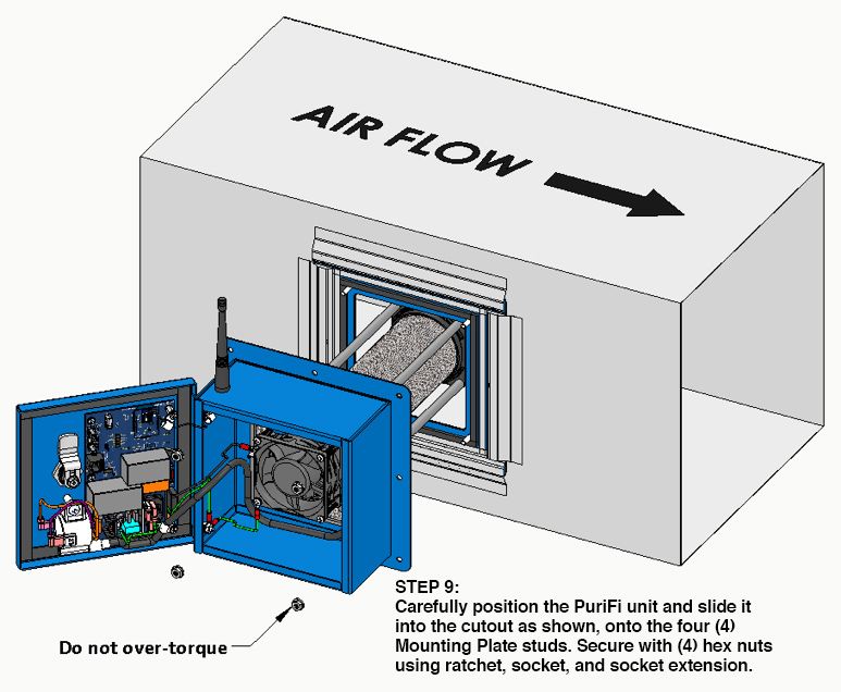
PuriFi Labs Page 23 of 40 Phoenix, Arizona, USAINSTALLATION SEQUENCE PuriFi Labs Page 24 of 40 Phoenix, Arizona, USA
PuriFi Labs Page 25 of 40 Phoenix, Arizona, USA
PuriFi Labs Page 26 of 40 Phoenix, Arizona, USA
PuriFi Labs Page 27 of 40 Phoenix, Arizona, USA
PuriFi Labs Page 28 of 40 Phoenix, Arizona, USA
Figure 5 – Installed PuriFi™ Generator Unit

INSTALLATION – ELECTRICAL

WARNING: This product should only be installed by a trained and certified electrician or HVAC
contractor. This unit generates nearly 5000 VAC at the ionization tube. DO NOT connect supply power
until installation is complete. ALWAYS disconnect power before handling any of the unit components.
There is a door safety interlock switch that prevents the PuriFi™ unit from operating if the enclosure door
is open. DO NOT attempt to defeat this safety switch and DO NOT ever attempt to operate the unit while
the door is opened.

NOTE: the PuriFi™ high voltage components and control circuitry are protected inside of a metal
enclosure, and should only be accessed by a licensed professional. There are no user serviceable
replacement parts inside the unit. A special key is required to open the enclosure door.

PuriFi Labs                                    Page 29 of 40                            Phoenix, Arizona, USA
CAUTION: This unit has a grounding type 3-prong plug to reduce the risk of electrical shock. Contact a
qualified, certified electrician to ensure that the outlet is grounded. NEVER remove the third prong or
alter the plug in any way.

The PuriFi Generator has been designed to operate with a wide
range of input voltages, and is shipped from the factory with a 1
Amp slow-blow fuse inside of the IEC-60320 C14 standard power
entry module.

A C13 to 5-15P (standard USA 3-Prong Style) power cord is
provided with the unit from the factory. If your particular
installation requires a different plug than what is provided as
standard, PuriFi Labs suggests contacting Interpower Corporation
(www.interpower.com) for obtaining the proper cord, which will
be a C13 (Purifi end) to the wall socket you are providing power
with.                                                                 Figure 6 - Power Entry Module

POWER CONNECTION REQUIREMENTS
The PuriFi unit requires a primary power source between 100-240VAC, at either 50 or 60Hz. The electrical
service to this unit must conform to local, national, and international safety codes where applicable, and
must be carried out by qualified individuals.

It is imperative that the unit be properly grounded to local codes. The standard PuriFi unit draws
approximately 15 Watts of power, and its power source should be protected by either a 15 or 20A breaker
(maximum).

NOTE: The unit is designed to operate with a continuous power supply voltage. Do not install this unit
where it can be turned on or off remotely, or where the supply voltage can be cycled.

HVAC CONNECTION REQUIREMENTS
The PuriFi™ Generator can interface with the HVAC system in two specific ways, and has an additional
‘Ozone Depletion Mode’ that it can operate in without interfacing with the HVAC system:
     1) (Mode 1) the unit will ionize air when it senses that the HVAC fan unit has turned on. When the
        HVAC fan turns off, the PuriFi Generator will stop ionizing. This is basic operation and does not
        include smart/adaptive air quality monitoring.
     2) (Mode 2) The PuriFi Generator can take control of the HVAC unit’s fan, turning the system fan on
        whenever the PuriFi Sensor detects an air quality issue and alerts the Generator. NOTE: make
        sure that any warranties that you have with the HVAC unit are not affected should you choose to
        run the PuriFi unit in this mode. Mode 1 will still be functional and the Generator will continue
        to run when the HVAC fan is manually activated or during HVAC heating and cooling cycles.
     3) Ozone Depletion Mode – the PuriFi unit will turn on its own internal fan and turn off ion
        generation for some percentage of time. This will draw system air from the plenum thru the
        proprietary catalyst and introduce it back into the plenum – thereby ‘scrubbing’ ozone from the
        air.

PuriFi Labs                                    Page 30 of 40                           Phoenix, Arizona, USA
Decide which mode (either Mode 1 or Mode 2 above) that you want the PuriFi Generator to operate in.
Once decided, make the proper relay control connections as follows. The major benefit of an ionization
system is best realized when the HVAC supply fan is running. To maximize your air quality and the negative
ion count in your environment, run the HVAC fan continuously or use an Indoor Air Quality (IAQ) type
thermostat that will cycle the fan several times an hour or at specified times during the day.
MODE 1 – the PuriFi unit will operate whenever the source HVAC unit fan is
powered on and distributing air through the duct system into the living space.
- Wire the HVAC fan connections to the left two connection points on the
4-position terminal block (front of PuriFi unit) titled FAN SENSE (24VAC
when Fan is ON). (See standard wiring diagram below)
MODE 2 – the PuriFi unit can operate the HVAC fan remotely, thus controlling
the distributed air through the duct system into the living space.
- Wire the HVAC fan connections to the right two connection points on the
4-position terminal block titled FAN REQUEST (Closed Contact when Fan
is desired). (See standard wiring diagram below) Figure 7 - HVAC Connections
OPERATION
The PuriFi Generator is designed to provide negative ionization into your living space in a smooth manner
by coordinating its operation with your HVAC unit’s fan or blower motor, and in conjunction with the PM
Particulate Matter Sensor and Home Automation “HUB” provided with the system. In the two modes
available, your HVAC unit can ‘turn on’ the PuriFi unit, thereby generating ions, or the PuriFi unit can ‘turn
on’ the blower motor. In either case, the air movement across the Purifi Generator will be distributed
throughout your home or establishment.
NOTE: Please discuss with your licensed HVAC contractor which mode will be best for your installation
requirements.
PuriFi Labs Page 31 of 40 Phoenix, Arizona, USAOnce the PuriFi™ Generator is correctly installed, you will enjoy the benefits of electronically purified air.
There are no end-user serviceable components in the PuriFi unit, and the STATUS LED information is
included here as reference only – please contact your licensed HVAC contractor for any service issues
related to the unit. The removable core unit has a service life of two (2) years before requiring
replacement.
MAINTENANCE & SERVICE
The PuriFi Generator has been designed to provide years of trouble-free service. To ensure the highest
quality air filtration, the unit monitors its run-time hours and requires that the Inner Module Assembly be
replaced on an annual basis. This replacement may be scheduled with your PuriFi Service Provider.
Diagnostic data is available wirelessly from the PuriFi unit to your home automation system (future) or
applications using internet and smart device technology. This data may be used for troubleshooting your
unit.
There are no user serviceable components inside the PuriFi unit. If the unit does not seem to be operating,
first check that the breaker has not tripped in your electrical panel. Second, disconnect power from the
unit and make sure that the fuse in the power entry module (front door of PuriFi unit) has not blown.
For any other service to the PuriFi Generator, please contact your Service Provider or Contractor.
FRONT PANEL STATUS LEDs
• [RED] Power Status: Solid RED = Normal Power; Blinking RED = Service Life Expired
• [GREEN] Solid Green = Radio Connected to another device, else not connected
• [YELLOW] Blinking Yellow = Radio Transmission occurring
• [BLUE] ION Generator Status (Detail Below)
1 Startup : 10 fast Blinks
2 Normal Operation : Solid Blue
3 Normal Standby : Blink Count = 1 (No External Fan is sensed, unit is waiting)
4 Normal Hold : Blink Count = 2 (Unit is temporarily in hold mode, see note below*)
5 Interlocked : Blink Count = 3 (Door is Open or other Interlock)
6 Internal Fan Failure : Blink Count = 4 (Internal Fan is not spinning)
7 Low Current : Blink Count = 5 (Core High Voltage path interrupted)
8 Excessive Current : Blink Count = 6 (Core High Voltage path potential leak)
9 Excessive Current : Blink Count = 7 (Unit is inoperable, possible short circuit)
* NOTE: There are a number of different reasons the unit might be on hold. These include the off cycle of Ozone
Depletion Mode, the unit receiving radio commands to go on hold as ions are high enough, excess temperature or
even core service life expiration. Most of these are temporary and will clear by themselves (except for the core
service life expiration case, which is uniquely identified by the red LED blinking).
PuriFi Labs Page 32 of 40 Phoenix, Arizona, USAINSTALLATION – PM PARTICULATE MATTER SENSOR
The PuriFi™ PM Sensor has been designed to plug directly into a wall outlet, for convenience, or to be
positioned wherever the end user would like to sample the air. In the instance where it is not suitable to
plug in to an outlet, the 110-240VAC transformer may be removed from the bottom of the sensor by
grasping it firmly and sliding it downward.
Once the transformer is removed, it will expose a standard USB
2.0 Type A plug. (See Figure at right)
The PM Sensor may be powered and is operational by three
methods:
1. Using the 100-240VAC transformer and plugging into a wall
outlet or suitable extension cord.
2. Removing the transformer and plugging a standard USB
Micro cable into the backside connector (rear of Sensor)
3. Removing the transformer and plugging a standard USB 2.0
Type A cable into the appropriate connector (bottom of
Sensor as seen at right).
A colored LCD Display on the front of the PM Sensor will show the particulate
counts and will change color according to the settings of “Clean”, “Cleaner” or
“Cleanest as described elsewhere in this manual. These PM settings can be
user defined but PuriFi Labs does not suggest changing the default settings,
however.
Most importantly, locate the sensor at least 3 feet off of the ground, and most
preferably in the “breathing zone”. We suggest not locating near bathrooms
or kitchen areas because of the typically high particulate
count.
The PM Sensor particulate measurements are sent via Zigbee
RF radio module to the Generator, which will enable and
control the ionization and purification based upon the User
Settings or Factory Defaults.
PuriFi Labs Page 33 of 40 Phoenix, Arizona, USATROUBLESHOOTING & FAQ
Wired internet connection is not available for the Hub / Internet connection is weak.
If a customer’s internet connection is weak and/or you need to provide a hardwired port for internet
connectivity, we recommend the GL.iNET GL-MT300N-V2 Wireless Mini Portable Travel Router WiFi
device available from Amazon ($32)
The Hub recognizes that it is “plugged in” to the network but cannot connect to the internet.
This is most likely a problem tied to network configuration. In the majority of cases, customers’ routers
are too old to support the Hubitat and they might need a new router (routers that are older than about
10 years old generally have difficulty supporting smart home devices). The other possibility is that
customer’s network has static IP addresses and/or they have intentionally limited internet access to
certain devices (MAC control). For the Hub to work properly, DHCP (dynamic routing) should be turned
ON at the network level and MAC access control should be turned OFF (or the Hub’s MAC address must
be added to the network as an approved device).
Devices have lost communication with the Hubitat app.
If dates and times are not showing current then proceed to the following:
(You will have to repeat each of these steps for every device that is not showing a current date
and time.)
Step 1: Click on Devices on the left hand side of the screen and select the device that
we want to reestablish communication with.
Step 2: Click the “POLL” tab to reestablish communication. Then scroll down to the
Bottom of the page to check current activity. If it changed to a current date and
Time then you are finished. (If the date and time did not change see how to
Perform a factory reset on page 34.)
In dashboard, if you click on the tiles on the right and the corresponding fan does not turn on then
perform the following:
PuriFi Labs Page 34 of 40 Phoenix, Arizona, USAStep 1: First check the wiring diagram on page 28 to make sure the low voltage to the
generator is correct.
Step 2: Open the door on the generator check the fuse on the circuit board shown
below. (If Steps 1 & 2 do not turn the fan on then perform a factory reset on
page 37.)
Air quality issues can trigger a heating or cooling request rather than a fan request as intended.
This issue is most likely related to the power configuration in the thermostat. Thermostats that include a
jumper that bridges RH/RC can create a feedback loop that activates the cooling/heating cycle. Remove
any jumpers (if possible) or upgrade the thermostat.
If the thermostat needs to be replaced, we recommend upgrading to a modern/smart thermostat.
Using a relay to take control of the fan wire is another way to bypass the thermostat:
PuriFi Labs Page 35 of 40 Phoenix, Arizona, USANo fan wire is available for installation and/or the HVAC system is a “communicating” system. Many higher-end HVAC systems do not include the conventional thermostat wiring because the system communicates directly with the thermostat wirelessly. If you encounter a communicating system, you will need to install a current sensing relay to activate the PuriFi system. How do I change my settings (clean, cleaner, cleanest)? You cannot change settings from the PuriFi™ Dashboard or on the PuriFi App, but they are customizable in the Hubitat App (see p. 12 in the Setup and Installation Guide). Go to Settings > Local Hub Discovery > [tap the name of the hub to be configured] > PuriFi Stat. You can adjust the ON ABOVE and OFF BELOW settings for all three modes within this menu. You DO NOT have to adjust the values. When values have been set to the desired level, hit NEXT at the bottom. The second screen allows you to specify air quality levels of Clean, Cleaner, or Cleanest by zone. If the dashboard does not reflect clean, cleaner, or cleanest setting, then the sensors themselves might need to be reset due to connectivity. If connectivity is the issue, then the dashboard will not show that the settings have been adjusted on the PuriFi Stat. PuriFi Labs Page 36 of 40 Phoenix, Arizona, USA
Factory Reset Generator or Sensor
(Only perform this on devices not reporting to the Hubitat App as expected)

Step 1:           Remove devices from the hubitat.
          Step 1a:      Click on “Devices” on the left hand side of the screen
          Step 1b:      Click on the device you would like to remove
          Step 1c:      Scroll to the bottom and click “Remove Device”

Step 2:           Cycle power 5 times on either generator or sensor
          Step 2a:        On the generator- after you cycle power the green hub light will be removed.
          Step 2b:        On the sensor- after you cycle power the blue light in the top left corner
                          should begin to blink.

Step 3:           Remove Hubitat Dashboard and CleanAirEXP Stat from Apps
          Step 3a:      Click on “Apps” on the left hand side of screen then click on the “gear” next to
                        the Hubitat Dashboard. Scroll down and click “Remove Hubitat Dashboard.”

PuriFi Labs                                     Page 37 of 40                          Phoenix, Arizona, USA
Step 3b: Click on the “gear” next to the CleanAirEXP Stat. Scroll down and click
“Remove CleanAirEXP Stat.”
TURN TO PAGE 14 AND COMPLETE STEPS 4-7 UNDER
“COMMERCIAL/CUSTOM INSTALLATION”
TO RECONNECT THE PURIFI HARDWARE TO THE HUB.
PuriFi Labs Page 38 of 40 Phoenix, Arizona, USASAFETY INSTRUCTIONS
Directions for Use
It is a violation of Federal Law to use this product in a manner inconsistent with its labeling.
• This product is intended for use in central HVAC systems (“duct-mounted” installation) only. Consistent airflow of 100 – 3000 CFM is
required while the unit is in operation. This product has not been tested for use in any other settings.
• Only a Certified Professional Installer should perform the installation of the PuriFi ionization system.
• This product must be installed in accordance with all applicable building codes.
This device complies with Part 15 of the FCC Rules. Operation is subject to the following two conditions: (1) This device may not cause harmful
interference, and (2) this device must accept any interference received, including interference that may cause undesired operation.
NOTE: This equipment has been tested and found to comply with the limits of Part 15 of the FCC Rules. These limits are designed to provide
reasonable protection against harmful interference in a residential installation. This equipment generates, uses and can radiate radio frequency
energy and, if not installed and used in accordance with the instructions, may cause harmful interference to radio communications. However,
there is no guarantee that interference will not occur in a particular installation. If this equipment does cause harmful interference to radio or
television reception, which can determined by turning the equipment off and on, the user is encouraged to try and correct the interference by
one or more of the following measures:
• Reorient or relocate the receiving antenna
• Increate the separation between the equipment and receiver
• Connect the equipment into an outlet on a circuit different from that to which the receiver is connected.
• Consult the dealer or an experienced radio/TV technician for help.
The PuriFi Generator’s main controller board has two (2) female headers that accept different plug-in radio modules. These radio modules are
pre-certified, and the FCC certification may be found at https://www.fcc.gov/oet/ea/fccid for the source of the PDF files noted in this manual.
There are presently four (4) RF radio module variations already available or in development.
1. U-BLOX BMD-34X BLE 5.0 ZIGBEE MODULE 2.4GHZ
a. FCC ID: XPYBMD341
2. DIGI XBEE AND XBEE-PRO MODULES 2.4GHZ
a. FCC ID: MCQ-XBSX or MCQ-XBPSX or CE/RED
3. ESPRESSIF SYSTEMS ESP32-WROOM-32XX WIFI PLYS BLE IOT MODULE 2.4GHZ
a. FCC ID: 24AC7Z-ESPWROOM32UE or 2AC7Z-ESPWROOM32E
4. MURATA CMWX1ZZABZ-078 LORA MODULE SMD 868/915 MHZ
a. FCC ID: VPYCMABZ
Caution: This product shall not be installed behind a suspended floor/ceiling or a structural wall, ceiling, or floor.
Caution: This product is suitable for mounting to duct of metallic construction only. Installation must be such that the structural integrity of the
ducting is not compromised.
Use temperature – Maximum Ambient temperature in which unit shall be used: 180 degree F / 82.2° C.
CAUTION – HIGH VOLTAGE.
WARNING: RISK OF ELECTRICAL SHOCK. Can Cause Injury or Death: Disconnect All Remote Electric Power Supplies Before Servicing.
CE Listed: You may request a copy of the CE Declaration of Conformity at any time by contacting brand@purifilabs.com
PuriFi Labs Page 39 of 40 Phoenix, Arizona, USAWARRANTY INFORMATION LIMITED FIVE (5) YEAR WARRANTY Customer should not repackage and ship the PuriFi™ system due to possibility of irreparable damage. For warranty service, please contact your independent HVAC contractor for the address of the nearest service center or call PuriFi Labs Customer Service at 1-602-253-2624. WHAT IS COVERED BY THIS WARRANTY We warrant the PuriFi air purification device (p/n: IAI-100) to the Customer, subject to the conditions below, against defects in workmanship or material, provided that the products are returned to a service location within five (5) years of date of purchase. PuriFi Sensors (p/n: IAI-400) and Hubs (p/n: IAI-HUB7) are warranted for 24 months from date of installation or 34 months from the date of shipping from the manufacturer, whichever comes first. INSTALLATION AND MAINTENANCE REQUIREMENTS This warranty is expressly conditioned upon proper installation, operation, cleaning and maintenance according to this Owner’s Manual. Failure to meet any of these requirements will void this warranty. Servicing of the PuriFi system by parties other than our authorized representatives and/or using parts other than genuine parts will also void this warranty. HOW TO OBTAIN WARRANTY SERVICE Customer must contact their independent HVAC Contractor and provide proof of purchase within the above time periods. PuriFi Labs will repair or replace and return the product, without charge and within a reasonable period of time, subject to the conditions herein, if its examination shall disclose any part to be defective in workmanship or material. If we, in our discretion, are unable to repair the product after a reasonable number of attempts, we will provide either a refund of the purchase price or a replacement unit, at the company’s option. We reserve the right to inspect and /or require confirmation of installation method. WHAT IS NOT COVERED BY THIS WARRANTY Ordinary wear and tear shall not be considered a defect in workmanship or material. These warranties do not apply for loss or damage caused by accident, fire, abuse, misuse, improper installation, leaking, modification, misapplication, or by any repairs other than those provided by our authorized Service Center. This Warranty is non-transferrable. MISSING SERIAL NUMBERS AND UNAUTHORIZED CHANNELS If a valid serial number is missing from the product, the Warranty will be voided. PuriFi Labs products are for sale through authorized Independent HVAC Contractors only. Warranties are voided if a product is purchased through unauthorized channels; this includes company sponsored or independent websites that are not authorized to use PuriFi Labs’ trademarked names, images and logos as well as Internet auction sites (e.g. EBAY and Craigslist). The only approved company sponsored or independent Internet sites for PuriFi Labs products is www.purifilabs.com. To confirm warranty coverage prior to purchasing a product or requesting service on a product, first contact your Licensed Installer, or contact PuriFi Labs at 1-602-253-2624 (1-602-CLEAN-AIR) with the serial number located on the unit. EXCLUSION OF OTHER WARRANTIES AND CONDITIONS EXCEPT AS PROVIDED HEREIN, PURIFI LABS MAKES NO REPRESENTATION OR WARRANTY OF ANY KIND. ALL OTHER WARRANTIES OF ANY KIND, EXPRESS OR IMPLIED, ARE HEREBY EXPRESSLY DISCLAIMED, INCLUDING ANY IMPLIED WARRANT OF MERCHANTIBILITY OR FITNESS FOR A PARTUICULAR PURPOSE. LIMITATION OF LIABILITY FOR SPECIAL, INCIDENTAL, OR CONSEQUENTIAL DAMAGES PURIFI LABS SHALL NOT IN ANY CASE BE LIABLE FOR SPECIAL, INCIDENTAL OR CONSEQUENTIAL DAMAGES ARISING FROM BREACH OF EXPRESSED OR IMPLIED WARRANTIES, CONDITIONS, GUARANTEES OR REPRESENTATIONS, BREACH OF CONTRACT, NEGLIGENCE OR ANY OTHER LEGAL THEORY. FOR U.S. APPLICATION ONLY This Warranty gives you specific legal rights, and you may also have other rights which vary from state to state. Some states do not allow limitations on warranties, or on remedies for breach. In such states, the above limitations may not apply to you. SERVICE Every effort is made to ensure customers receive an up-to-date Owner’s Manual on the use of PuriFi Labs products; however, from time to time, modifications to PuriFi Labs products may without notice make the information contained herein subject to change. For the latest information on PuriFi Labs products, please visit our website. PuriFi Labs Page 40 of 40 Phoenix, Arizona, USA
You can also read