ECU LAN For the Building Access System or Stand-Alone Applications - USER MANUAL - DPS Telecom
←
→
Page content transcription
If your browser does not render page correctly, please read the page content below

ECU LAN
      For the Building Access System
        or Stand-Alone Applications
                                 USER MANUAL

        Visit our website at www.dpstelecom.com for the latest PDF manual and FAQs.

February 19, 2021                 D-UM-ECULN-12001                    ECU LAN Firmware Version 1.0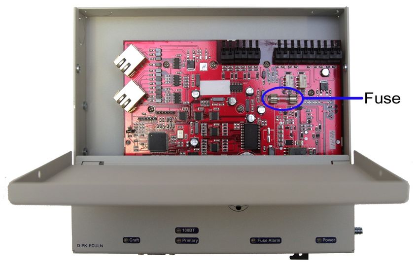
Revision History

               February 19, 2021        Section 3.5.2 update

               October 23, 2020         Display Mapping update

               October 20, 2015         Speaker Settings

               August 10, 2015          Update screenshots

               June 30, 2015            Update to Email Notifications

               May 27, 2015             Minor additions to web browser sections

               April 28, 2015           BAC Global Provisioning update

               February 26, 2014        Added HID Proxy/Keypad Combo to Hardware Installation Section

               May 13, 2011             Initial Release

This document contains proprietary information which is protected by copyright. All rights are reserved. No part of this
document may be photocopied without prior written consent of DPS Telecom.

All software and manuals are copyrighted by DPS Telecom. Said software and manuals may not be reproduced, copied,
transmitted or used to make a derivative work, by either mechanical, electronic or any other means in whole or in part, without
prior written consent from DPS Telecom, except as required by United States copyright laws.

© 2021 DPS Telecom

Notice
The material in this manual is for information purposes and is subject to change without notice. DPS Telecom shall not be
liable for errors contained herein or consequential damages in connection with the furnishing, performance, or use of this
manual.
Contents
                  Visit our w ebsite at w w w .dpstelecom .com for the latest PDF m anual and FAQs

1 Introduction                                                                                        1
  1.1 Proxy and Keypad Support                                                                        3
  1.2 Shipping List                                                                                   4
2 Specifications                                                                                      7
3 Hardware Installation                                                                               8
  3.1 Site Preparation                                                                                8
  3.2 Installation Overview                                                                           8
  3.3 Mounting Instructions                                                                           9
       3.3.1 Entry Control Unit                                                                       9
       3.3.2 ECU with conduit                                                                         9
       3.3.3 Keypad                                                                                  10
       3.3.4 Card Reader                                                                             10
  3.4 Opening the Case                                                                               11
  3.5 Power Connection                                                                               12
       3.5.1 Entry Control Unit                                                                      12
       3.5.2 Door Strike                                                                             14
       3.5.3 ECU LAN Internal Fuse                                                                   16
  3.6 Communication Lines                                                                            17
       3.6.1 Keypad                                                                                  17
       3.6.2 Proxy Reader                                                                            18
       3.6.3 HID ProxPro Keypad/Proxy Reader                                                         19
4 Speaker and LEDs                                                                                   20
  4.1 Front Panel LEDs                                                                               21
       4.1.1 LED Verification and Local Testing                                                      22
  4.2 Speaker Operation                                                                              22
       4.2.1 ECU Internal Speaker                                                                    23
  4.3 Keypad LED Operation                                                                           24
       4.3.1 Basic Operation                                                                         24
5 Basic Unit Configuration                                                                           26
  5.1 Provisioning an IP Address                                                                     26
6 Advanced Unit Configuration (Web Interface)                                                        28
  6.1 Logging in to the Web Interface                                                                28
  6.2 Edit Menus                                                                                     29
       6.2.1 System                                                                                  30
       6.2.2 Ethernet                                                                                31
       6.2.3 Notifications                                                                           32
               6.2.3.1 Email Notification Settings                                                   33
               6.2.3.2 SNMP Notification Settings                                                    33
               6.2.3.3 Relay Notification Settings                                                   34
               6.2.3.4 Notification Schedules                                                        34
       6.2.4 Alarms                                                                                  35
               6.2.4.1 System Alarms                                                                 35
       6.2.5 Controls                                                                                36
       6.2.6 BAC Globals                                                                             37
       6.2.7 BAC Profiles                                                                            39
       6.2.8 Date and Time                                                                           40
       6.2.9 Timers                                                                                  41
       6.2.10 Reboot                                                                                 41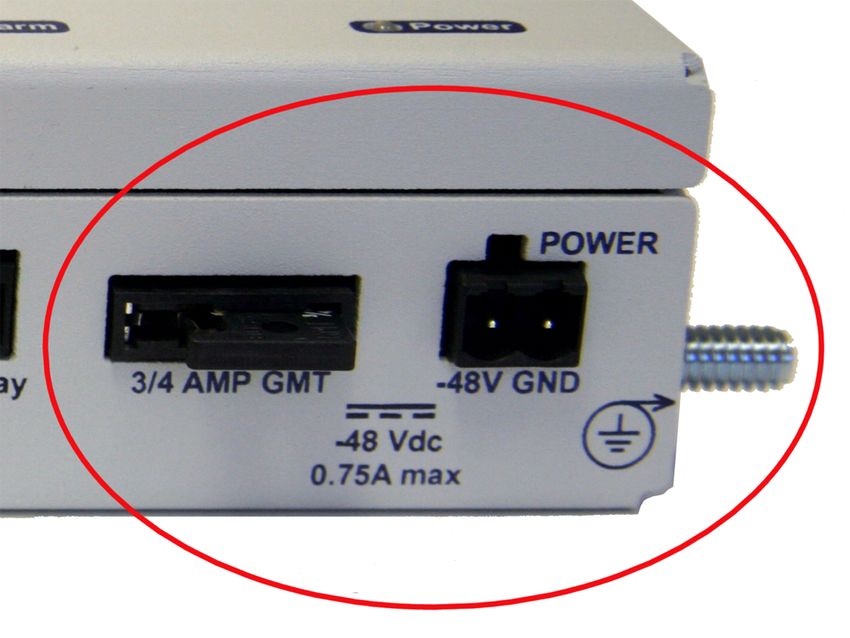
7 Monitoring Alarms and Issuing Controls   42
   7.1 Monitoring Alarms                   42
   7.2 Issuing Control Commands            43
   7.3 Site Access Log                     44
8 Firmware Upgrade                         45
9 Determining Proximity Card Number        46
10 T/Mon Configuration                     48
11 Display Mapping Appendix A              50
12 Technical Support                       52
13 End User License Agreement              53
1

1 Introduction
The Building Access System (BAS) is a comprehensive building entry management system that provides
centralized door access control utilizing your existing DPS network monitoring systems. With the system in place,
managers can maintain a database of all personnel access as well as the time of day and location that access was
granted.

Building access functionality typically requires an RTU to report to T/Mon and locally process entry requests made
through an entry control unit (ECU). The ECU LAN, however, grants or denies access on its own, performing both
the RTU and ECU functions of the traditional DPS building access environment. It communicates directly with T/Mon
to retrieve and report access data, stores its own access data locally, and issues control logic for a single door.

                        In the Building Access System, the ECU LAN operates independently of an RTU

With the ECU LAN, you can cheaply and easily add individual doors to your building access system to control
building access at small sites where you don't have or need an RTU. This allows you to extend building access
functionality to sites that would've otherwise been unmonitored or controlled by a completely separate system.

The ECU LAN:
    • Controls and regulates a single door entry point.
    • Stores entry data and access permissions locally so your site functions independent of the master.
    • Supports both keypad and proxy card entry methods.
    • Supports a dual proxy reader build option.
    • Is configurable through simple TTY and Web Browser interfaces
    • Can run in stand-alone mode for applications without T/Mon
2

           In "Standalone" mode, the ECU LAN can control door access without receiving access information from T/Mon

Keypad (Accessory Sold Separately)
The weather-shielded keypad is mounted on the exterior of the building and is designed to withstand a wide
temperature range. To prevent unauthorized access, there is no amount of tampering that can be done to the keypad
to cause the door to open.

Proxy Reader (Accessory Sold Separately)
The weather-proofed proximity reader is mounted on the exterior of the building and is designed to withstand a wide
temperature range. As with the keypad, there is no amount of tampering that can be done to the proxy reader to
cause the door to open. The ECU LAN supports +12V, 26-bit or 37-bit Wiegand card readers.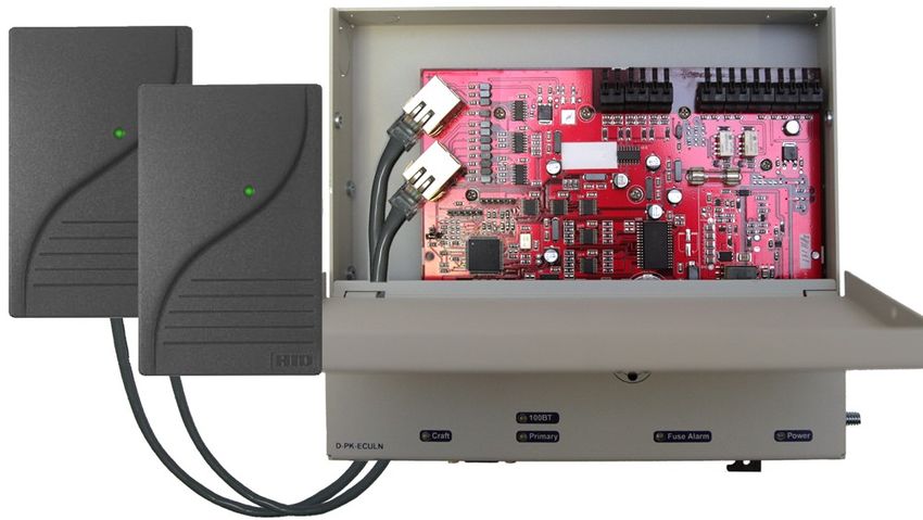
3

1.1 Proxy and Keypad Support
The ECU LAN is capable of working in multiple configurations with keypads, proxy readers, door strikes, and
magnetic door locks. While it supports dual proxy readers (one inside, one out) or one proxy reader and one
keypad, the ECU LAN cannot be used with two keypads.

                            ECU LAN Supports Proxy Reader and Keypad (1 each)

                                                        Or
                                    Dual Proxy Readers (1 inside, 1 outside)

Specialized Door Control Modes

"Dual Proxy Mode" - When purchased for this hardware configuration, you will mount one Proxy Card Reader
inside your building and one outside. This is used for logging personnel in and out of facilities.

"Magnetic Door Mode" - This configurable mode may be used with doors equipped with magnetic door locks. In
this mode, the door will remain magnetically locked until unlocked via proxy card scan, Request-to-Exit button, or
motion sensor.

 NOTE: Door violations occur when the door is opened without being unlocked. Pushing a Request-to-Exit button or
triggering the motion sensor after the intrusion will not cancel the violation.

"Lock When Closed Mode" - This mode causes the door to lock a few seconds after it has been detected closed,
and can be usefully combined with "Magnetic Door Mode" to ensure the door closes before being locked. In this
mode, if the door does not open after it has been unlocked, It will lock again after 2-3 seconds.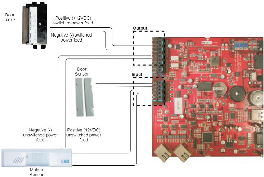
4

1.2 Shipping List
While unpacking the ECU, please make sure that all of the following items are included. If some parts are missing,
or if you ever need to order new parts, please refer to the part numbers listed and call DPS Telecom at (800) 622-
3314.

ECU LAN Box

Entry Control Unit
(D-PK-ECULN)                                                    Building Access user manual
                                                                (D-UM-ECULN-12001)

Two Mounting Ears                                               Four Ear Screws

                                                                One 2-pin power screw-lug jack
 One 2-pin fuse relay screw lug                                 (2-820-00862-02)
(2-820-00812-02)

Two 3/4 amp fuses
(2-741-00750-00)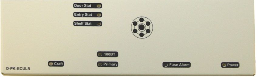
5

Keypad Box (Sold Separately)

                                     One 14 foot cable.
                                     (D-PK-KEYPD-12001.0001)
One environmentally sealed Keypad.
(D-PK-KEYPD-12001.0001)

Keypad mounting template
(D-OC-ECUMOUNTING)                   Four mounting screws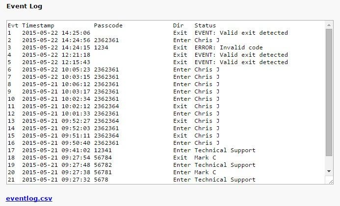
6

Proximity Reader Box (Sold Separately) (D-PK-PROXI-12001)

One HID ThinLine Proximity Card Reader      One demo card from HID
w/12" RJ-45 Cable                           (D-PR-534-10A-00)
(D-PR-530-10A-00)

One Unshielded RJ45 to RJ45 CAT 5 Coupler
(D-PR-534-10A-01)                           One HID Mounting Instructions

Two HID Mounting Screws
7

2 Specifications
       Specification          ECU LAN             Keypad (Sm)            Keypad (Lg)        Proxy Reader
         Dimensions      8.56” x 7.5” x 1.72”     3”x 5” x 2 ½ “       4 ½” x 5” x 2 ½”     4.7" x 3" x 0.68"
          Mounting           wall mount            wall mount             wall mount           wall mount
         Power Input          -48 VDC                  N/A                   N/A               5-16 VDC
        Current Draw           35 mA                   N/A                   N/A                 30 mA
          Interfaces        1 RJ45 LAN                RJ45                   RJ45                RJ45
                          1 DB9 Craft Port
          Protocols              N/A                   N/A                   N/A            Wiegand (26/37
                                                                                                 bit)
        Temp. Range          0° to 60°C            -40° to +80°C         -40° to +80°C        -30° to 65°C
                           (32° to 140°F)        (-40° to +176°F)      (-40° to +176°F)     (-22° to +150°F)
          Humidity           0% to 95%           environmentally       environmentally         0%-95%
           Range           non-condensing             sealed                sealed          non-condensing
            Fuse          Int. GMA 1 amp               N/A                   N/A                  N/A
                          Ext. GMT ¾ amp
           Audible            Speaker                  N/A                   N/A                Speaker
           Visual               LEDs                  LEDs                  LEDs                  LED

Note: Proxy reader specifications are based on the ThinLine II card reader from the HID Corporation.
      12VDC power is supplied to the reader by the ECU LAN.
8
3 Hardware Installation
3.1 Site Preparation
Tools needed:
Wire strippers/cutter
Phillips screwdriver
Small standard No.2
screwdriver (1/16" for screw-lug
connectors)
Materials needed:
• 1/2” conduit
Precautions
• Pull GMT fuse before connecting ECU power feed.
• Always observe electrostatic discharge (ESD) precautions.
3.2 Installation Overview
1. Mount the ECU and the Keypad and/or Proxy Reader.
2. Connect power to the ECU.
3. Connect communication lines between the ECU, LAN, and Keypad and/or Proxy Reader.
4. Set the ECU IP address via TTY interface.
5. Customize ECU LAN settings via the Web Browser Interface
6. Provision T/Mon with the appropriate information. (See the BAS software module in the T/MonXM user
manual for more information)9
3.3 Mounting Instructions
3.3.1 Entry Control Unit
The Entry Control Unit can be wall mounted by using the provided rack ears. These will need to be screwed onto
both sides of the unit.
Fig. 3.1
3.3.2 ECU with conduit
· The 3/4” circular openings support standard 1/2” conduit fittings (not included).
· Secure power and communication wires by installing 1/2” inch conduit in any
of the 3/4” circular openings on the ECU.
· To attach the conduit, remove the 3/4” pre-cut metal circles from the case and insert the 1/2” conduit or the nylon
plug.
Fig. 3.210
3.3.3 Keypad
1. Mount the keypad bracket on the desired surface using the four screw holes by using the mounting bracket.
2. Before securing the keypad onto the bracket, weave the RJ45 cable through the securing barriers and out the
circular bracket opening.
3. Secure the keypad onto the bracket by inserting the four side panel screws into the unit.
Fig. 3.3
3.3.4 Card Reader
1. Add RJ cable lead to the reader according to ECU pinout. Make sure cable length is adequate to reach the ECU
or use an RJ coupler w/CAT5 extension cable. Maximum cable length is 300 feet.
RJ45 Pin # HID Wire Color Function
1 Red +12 VDC Power
2 N/C Do Not Connect
3 White Data1
4 Green Data0
5 N/C Do Not Connect
6 N/C Do Not Connect
7 N/C Do Not Connect
8 Black Ground
RJ-45 pinout information
2. Mount the reader on the desired surface according to mounting instructions provided by card reader manufacturer.11
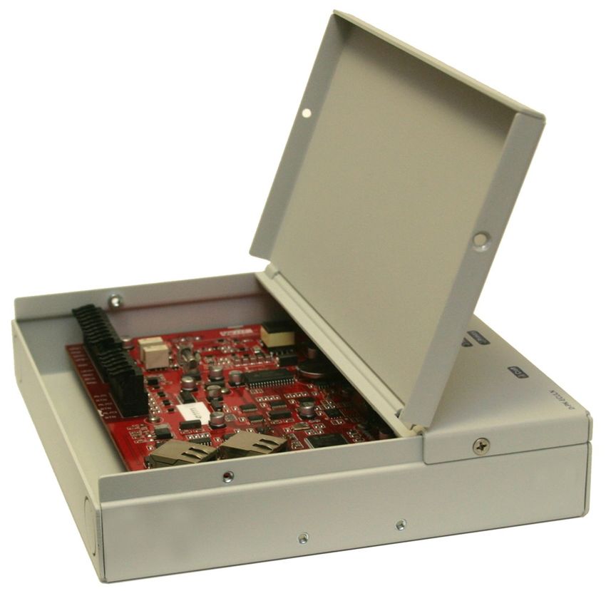
3.4 Opening the Case
The entire ECU cover does not need to be taken off to access the internal wire termination connectors, fuse or RJ45
connectors for the keypad and proxy reader. The front panel is broken up into two parts and hinges towards the
middle of the ECU. The upper half can be unscrewed and pulled open to access all of the ECU internal connections.
Fig. 3.4
To open the upper half of the ECU case:
1. Locate and remove the screws on both sides of the upper half of the unit.
Note: Do not remove the screws that are holding the bottom portion of the front panel.
2. Gently pull the top of the panel away from the unit to access the inside of the case.12
3.5 Power Connection
3.5.1 Entry Control Unit
The Grounding Lug on the side of the unit provides a permanent connection to earth ground when
connected. The Grounding Lug must be used in order to comply with CE standards.
ECU LAN GMT fuse slot, pow er connection, and grounding lug
Before you connect a power supply to the ECU, test the voltage of your power supply:
· Connect the black common lead of a voltmeter to the ground terminal of the battery, and connect the red lead of
the voltmeter to the battery's –48 VDC terminal. The voltmeter should read between –43 and – 53 VDC. If the
reading is outside this range, test the power supply.
To connect the ECU to a power supply, follow these steps:
1. Always use safe power practices when making power connections. Be sure to remove fuses from the fuse
distribution panel, as well as the ECU, before making your power connections.
2. Use the grounding lug to connect the unit to earth ground. The grounding lug is next to the symbol . Insert the
eyelet of the earth ground cable between the two bolts on the grounding lug (Ground cable not included).
3. Insert a battery ground into the power connector plug's right terminal and tighten the screw; then insert a battery
line to the plug's left terminal and tighten its screw.
4. Insert a fuse into the fuse distribution panel and measure voltage. The voltmeter should read between –40 and –13
70VDC.
5. The power plug can be inserted into the power connector only one way to ensure the correct polarity. Note that
the negative voltage terminal is on the left and the GND terminal is on the right.
6. Insert fuse into the Power fuse slot. The power LED should be lit green. If the LED is off, the power connection
may be reversed. To confirm that power is correctly connected, the front panel LEDs will flash RED and GREEN,
indicating that the ECU application has started.
Note: Observe polarity when connecting battery leads. If using the -48VDC red/black cables supplied with the unit,
connect black to GND and red to -BATT. Standard gauge is 20AWG, but may vary between 18-24AWG.
Fig. 3.6
FA Relay on the bottom of the unit contains the contact closures for the fuse relay. This will close when the 3/4
amp GMT fuse has blown and will normally be open. Use the included 2-pin screw lug.14
3.5.2 Door Strike
When a valid password is entered on the keypad, the ECU will operate the relay to energize the door strike. The
ECU will de-energize the relay if configured for magnetically controlled doors.
Follow the directions below to connect the door strike and door sensor to the ECU.
1) Use the screw-lug connectors. If using a 24VDC door strike, connect the door strike power wires to SPB (+) and
SNeg (-). If using a 12VDC door strike, connect the power wires to SPA(+) and SNeg(-).
2) Connect the door sensor to RTN (return) and ALM1 (opto isolated alarm for the door sensor).
Wiring diagram for connecting sensors and strikes to the ECU LAN15
Ou tp u t Co n n e ctio n s
Screw-Lugs Description
SPB+ Positive switched power source (24VDC). Can be used for door strike.
SNeg Negative switched power source. Can be used for door strike. This is used by either SPB+ or
SPA+.
SPA+ Positive switched power source (12VDC). Can be used for door strike.
UPB+ Positive un-switched power source. (24VDC)
UNeg Negative un-switched power source. This has 2 connections and both are the same. For use
with UPA+ or UPB+.
Can be used to power the motion sensor or other external accessory.
UPA+ Positive un-switched power source (12VDC). Can be used to power the motion sensor or other
external accessory.
RNO Relay normally open.
RCO Relay common.
RNC Relay normally closed
Input Connections
Screw-Lugs Description
ALM1 Isolated alarm for door sensor.
RTN Door sensor return.
ALM2 Request to exit (motion sensor)
RTN Motion sensor return.
ALM3 Available as a general purpose alarm input
RTN Alarm return
Tbl. 2.2.5.2b - ECU screw -lug jack descriptions16
3.5.3 ECU LAN Internal Fuse
If the unit fails to power the door strike, motion sensor, or proxy reader, then make sure the fuse inside the unit has
not blown.
Replace with a 1 amp GMA fuse (part number: 1-740-01000-00) if necessary.
The ECU LAN's internal fuse17
3.6 Communication Lines
3.6.1 Keypad
The keypad interfaces with the ECU via an RJ45 cable (attached to the keypad). The ECU has five circular openings
(two on top, two on the side and one on bottom) where the RJ45 cable can be inserted. The RJ45 jack is located on
the inside of the ECU casing. Insert the RJ45 cable through one of the openings and connect it to the RJ45 jack
labeled "Keypad/Proxy Inside".
Note: Your ECU LAN must be purchased with the keypad option in order to use the keypad accessory. Check your
product appendix to confirm the hardware build of your ECU LAN unit.
Connecting the keypad to the ECU via RJ-45 cable
Note: There is a maximum distance of 14 feet between the k eypad and the ECU.18
3.6.2 Proxy Reader
The proxy reader interfaces with the ECU via an RJ45 cable (attached to the proxy reader). The ECU has five circular
openings (two on top, two on the side and one on bottom) where the RJ45 cable can be inserted. The RJ45 jack is
located on the inside of the ECU casing. Insert the RJ45 cable through one of the openings and connect it to the
RJ45 port labeled "Proxy Outside".
Note: There is a recommended maximum distance of 300 feet between the proxy reader and the ECU.
Dual Proxy Mode
To use 2 proxy readers for entry and exit logging, connect the proxy reader located inside the building to the internal
port labeled Proxy Inside, and the proxy reader located outside the building to the port labeled Proxy Outside.
Note: Your ECU LAN must be purchased with the Dual Proxy hardware option in order to use Dual Proxy Mode
(Proxy Inside). Check your product appendix to confirm the hardware build of your ECU LAN unit.
Connecting the proxy reader to the ECU via RJ-45 cable
RJ45 Pin # HID Wire Color Function RJ45 Connector
1 Red +12 VDC Power
2 N/C Do Not Connect
3 White Data1
4 Green Data0
5 N/C Do Not Connect
6 N/C Do Not Connect
7 N/C Do Not Connect
8 Black Ground
RJ45 pinout information (Proxy reader)19
3.6.3 HID ProxPro Keypad/Proxy Reader
The proxy reader/keypad interfaces with the ECU via an RJ45 cable. The ECU has five circular openings (two on top,
two on the side and one on bottom) where the RJ45 cable can be inserted. The RJ45 jack is located on the inside of
the ECU casing. Insert the RJ45 cable through one of the openings and connect it to the RJ45 jack labeled "Proxy
A" or "Proxy B".
First, remove the front plate of the ProxPro unit. After the front plate has been removed, 4 holes
containing screws will be revealed. Remove all 4
screws.
Match the corresponding wire to the screw connector.
From the inside of the unit, locate the screw See pinout table below for additional information.
connectors. This is where you'll attach the wires to the
RJ45 connector.20
Match the corresponding wire to the appropriate pin on Put the two pieces back together. First, on the inside
the RJ45 connector. See pinout table below for cover, locate the 10-pin male connector. This
additional information. connector will need to correspond to the 10-pin female
connector on the board on the base unit (image
below).
RJ45 Connector
RJ45 Connector Pinout ProxPro Connector Pinout
RJ45 Pin # Function Connector* Function
1 DC+ (Red) 1 DC+ (RED)
2 No Connect 2 Ground (BLACK)
3 Data 1 3 Data 1/Clock (WHITE)
4 Data 0 4 Data 0/Data (GREEN)
5 No Connect 5 No Connect
6 No Connect 6 No Connect
7 No Connect 7 No Connect
8 Ground 8 No Connect
*Starts from DC+ (RED) and goes down vertically
4 Speaker and LEDs21
4.1 Front Panel LEDs
The ECU's LEDs give at-a-glance status indication.
Fig. 5.1
LED Status Description
There is no power, or -48V and Ground
Off
Power on power connector are reversed.
Solid Green Power is on and correctly configured
Fuse Alarm Solid Red Blown Fuse
Door Relay Active (i.e door unlocked)
Or
Solid Green “Propped Door Mode” is active
Or
Door Stat "Stay Open Door Mode" is active
Lockout (prevents user access for 5
Solid Red
minutes)
Blink Red Open door lockout
Entry Stat Blink Green Card Read is being processed
Slow Blink Green Receiving polls normally
Shelf Stat ECU LAN is operating in Stand-Alone
Slow Blink Red
Mode
LAN connection is 10BaseT or not
Off
100BT connected
Solid Green LAN connection is 100BaseT
Transmit serial communication to T/
Blink Green
Mon
Primary
Receive serial communication from T/
Blink Red
Mon
Blink Green Transmit Serial Communication to PC
Craft
Blink Red Receive Serial Communication from PC
ECU LAN LED Descriptions22 4.1.1 LED Verification and Local Testing Upon powering up the ECU, all of the unit's panel LEDs (except for Power and 100BT) will flash between green and red. If the unit is functioning properly, the Shelf Stat LED will flash green every 2 seconds (this functions as a unit status indicator - if the Shelf Stat LED is flashing red it means the unit is not communicating with T/Mon and is operating in Stand-Alone Mode. During normal communication with the T/Mon, the Primary LED will rapidly alternate between green and red. 4.2 Speaker Operation The ECU offers the following audible notification of specific events: *Configurable in the Provisioning > Timers page under Door Warning Beep. **Configurable in the Provisioning > Timers page under Time Before Door Violation. Normal Entry Operation After entering a valid “Entry” password or card scan and the door strike has been energized, users have approximately 55 seconds** to enter through the door and close the door behind them before an alarm condition occurs. Once a valid “Entry” password is accepted by the ECU, a 25-second* silent time-lapse will occur followed by a 30-second slow (warning) beep, during which time the user must enter through the door and close it behind them. An alarm condition will occur after 55 seconds and will be indicated by a faster beep. Normal Exit Operation Upon exiting through the door, users must enter a valid “Exit” password or card scan within 30 seconds of opening the door. A 30-second slow (warning) beep will sound during which time the user must close the door and enter valid “Exit” password before an alarm condition occurs. Normal Exit Operation (With Request-to-Exit) An optional motion sensor can be tied to ALM2 to signal a request-to-exit scenario. You would do this if you don't want to enter a password or card scan during exit. During a request-to-exit, the person exiting has approximately 55 seconds** to close the door behind them before an alarm condition occurs. A 25-second* silent time-lapse will occur followed by a 30-second slow (warning) beep, during which time the user must exit through the door and close it behind them. An alarm condition will occur after 55 seconds** and will be indicated by a faster beep. Door Alarm A fast beep indicates a door alarm has occurred. The user must re-enter or re-exit (with a valid password or card scan) in order for the alarm to clear. While the door alarm remains standing (uncleared), the speaker will cycle between 12 minutes on (fast beep) and 3 minutes off. Because a fast beep indicates a door alarm, open door lockout will be canceled, and the keypad or reader will be enabled, even if the door is open. A T/Mon administrator can also cancel the door alarm by issuing a MOM door unlock command. Propped Door Mode T/MonXM can issue a “Propped Door Mode” by issuing a MOM control command to point 21,which will allow the door to be held open without an alarm for up to 15 minutes. The speaker will not sound while the “Propped Door Mode” is active. Door violation alarms will not post while the “Propped Door Mode” is active. However, users should continue to submit passwords as they enter and exit the building. A beep indication will be given during the last 2 minutes if the door is open to show the command is about to expire. See the Building Access System software module in the T/Mon user manual for information regarding issuing a “Propped Door Mode” command.
23

Extended Propped Door Mode
The "Extended Propped-Door Mode" feature can be engaged by remotely issuing an OPR control command from
the T/Mon to point 22. The door may be opened and closed freely with no door violations for an indefinite
period of time. The door will be locked when closed. With the door closed, exit this mode by remotely issuing
an RLS control command to point 22.

Caution: Extended propped-door mode will not auto-expire.

Stay-Open Door Mode
You can enter "Stay-Open Door Mode" in one of two ways:
       i. Scan any card defined in T/Mon for that door with Stay-Open parameter set to 'Yes'
      ii. Remotely issue an OPR control command for both points 17 and 22

Points 17 and 22 will be active during Stay-Open Mode. The door will be unlocked and no door violations
will occur.

With the door closed, you can exit Stay-Open mode in one of two ways:
        i. Scan any card defined in T/Mon for that door with Stay-Open parameter set to 'Yes'
       ii. Remotely issue RLS control command to point 22. Point 17 will automatically clear,
           which will lock the door.

Caution: Stay-Open mode will not auto-expire.

4.2.1 ECU Internal Speaker

                                                       Fig. 5.2

Internal Speaker Volume Control
The volume control for the internal speaker can be found on the bottom of the unit next to the Fuse Alarm relay and
the primary connections.

Disabling the Speaker
To disable the speaker, remove the J10 jumper from the ECU circuit board. This shunt is not accessible from the
hinged door and requires full removal of the lid. It may be more convenient to disable the speaker by intentionally
lowering the volume so that it cannot be heard.
24
4.3 Keypad LED Operation
The Keypad LED indicators show keypad activity and access status. See table 4.2 for specific LED descriptions.
LED Status Description
Flashing Green Button on keypad is being pressed
OK (Green)
Solid Green Access granted (Door will remain unlocked for 5 sec.)*
Flashing Red Access code denied
ERR (Red)
Solid Red Lockout (prevents user access for 5 minutes)
Keypad LED indications
*Door unlock time is configurable via the Web Edit Interface. (See the subchapter of Advanced Unit Configuration
(Web Interface) titled Controls for more information.)
4.3.1 Basic Operation
Accessing a door (Outside - In)
Enter a valid access code on the keypad followed by “1” and then the pound “#” key (In)*. If access is granted, the
“OK” LED will be solid green and you will hear a “click” sound (this is the solenoid activating). The door will
remain accessible (solenoid active) for 5 seconds. The door must be closed within 25 seconds before the
ECU speaker sounds a warning and within 55 seconds before an alarm condition occurs.**
Exiting (Inside - Out)
Open the door from the inside and exit through the door. The door must be closed before the “exit” password can
be entered. Once the door is closed, enter a valid access code followed by “4” and then the pound “#” key (Out).
The “OK” LED will flash green if the user has successfully entered a valid password upon exiting. The “exit” code
will not enable the solenoid and therefore you will not hear a “click” sound as is heard when a valid “In” code is
entered. However, magnetic door mode will unlock the door on both entry and exit.**
Lockouts
A 5 minute lockout occurs if 6 invalid codes are entered consecutively in a period of 10 minutes. However,
pressing the “*”(star) button causes the unit to clear all prior key presses (a 10 second delay also clears prior
key presses). Alternatively, a manual activate door strike command will override the lockout.25 An “Open Door” lockout disables the keypad and/or proxy reader when any of the following conditions occur: 1. Door is open 2. There is no door alarm 3. The door is not propped enabled*. * If the door is propped open, users should still enter Entry/Exit passwords for T/MonXM event log recording. ** If sites are set to “Directional” and a user doesn’t log out (i.e. doesn’t press “4 #” after the access code), the T/Mon administrator can “force” log out that user. Additionally, if sites are set to “Non-directional”, and a user gets out of synch with entering “in” and “out” codes (i.e. forgetting to enter an exit code), the user may have to either log themselves b ack in or log themselves b ack out b efore their code will work again.
26

5 Basic Unit Configuration
To configure your ECU LAN, you must first provision the unit with an IP Address. You will configure the unit's IP address,
subnet mask, and gateway, via the ECU LAN's TTY interface, accessed via HyperTerminal (or a similar terminal emulator) over
a serial connection.

                                                    The ECU LAN Craft Port

To begin configuring the unit, connect the DB9 male to female cable that came with your ECU to the unit's craft port and your
PC's serial port.

5.1 Provisioning an IP Address
 You must be connected via craft port or Telnet to use the TTY interface. We'll be using HyperTerminal to connect
 to the unit in the following example - however, most terminal-emulating programs should work.

 To Configure your ECU LAN's IP Address:
 To access HyperTerminal using Windows:
 1. Click on the Start menu > select Programs > Accessories > Communications > HyperTerminal.

 2. At the Connection Description screen, enter a name for         3. At the Connect To screen, select Com port you'll
 this connection. You may also select an icon. The name            be using from the drop down and click OK. (COM1
 and icon do not affect your ability to connect to the unit.       is the most commonly used.)

 4. Select the following COM port options:                         5. When prompted, enter the default username
27
• Bits per second: 9600 admin and password dpstelecom. NOTE: If you
• Data bits: 8 don't receive a prompt for the username, try
• Parity: None pressing Enter to receive the prompt. If that doesn't
• Stop bits: 1 work, check the Com port you are using on your PC
• Flow control: None and make sure you are using the cable provided.
Once connected, you will see a blank, white
HyperTerminal screen. Press Enter to activate the Additional cables can be ordered from DPS
configuration menu. Telecom: Part number D-PR-045-10A-04
6. The ECU LAN's main menu will appear. Type C for C) 7. ESC to the main menu. When asked if you'd like
onfig, then E for E)thernet. Configure the unit's IP address, to save your changes, type Y for Y)es. Reboot the
subnet mask, and default gateway. ECU LAN to save its new configuration.28
6 Advanced Unit Configuration (Web Interface)
The ECU LAN features a built-in web browser interface for configuring and monitoring the unit through the Internet or
your Intranet. Beyond configuring the unit's IP address, most ECU LAN configuration will be performed via the unit's
Web Interface.
The ECU LAN's Web Interface allows for easy configuration and monitoring
Navigating the Web Interface
The Web Interface is split into 2 sections:
· The Monitor Menu allows you to monitor and control access to your door.
· The Edit Menu is where you'll configure system information, alarms, door controls, and notifications.
To navigate to any of the web interface menu options, simply click the option in the left side of the interface.
6.1 Logging in to the Web Interface
To login to the unit's web interface, simply type the IP address of the ECU LAN into the address bar of your web
browser. You will be prompted for your username and password.
The default username is: admin
The default password is: dpstelecom
DPS Telecom strongly recommends you change your username and password. See the System section later in
this manual for instructions on changing the default username and password.29
6.2 Edit Menus
ECU LAN configuration is performed from the Edit Menus, the menu options in green on
the left-side of the web interface. The following pages describe the options available in
each menu.
Saving Your Changes
At the bottom of each page is a Save button. When you have finished editing any ECU
LAN settings, click the Save button to commit your changes to the ECU LAN. Failure to
save changes before you navigate to another option or close the web interface will result
in the loss of your changes .
The ECU LAN Edit Menus30
6.2.1 System
From the Edit Menus > System screen, you can configure and edit global system settings for the ECU LAN. For
information on configuring system settings, see the table of field descriptions below.
The System Screen
Global System Settings
Name The name for the ECU LAN.
Location The location of the ECU LAN.
Contact telephone number for the person responsible for this ECU LAN unit. (Optional
Contact
field)
"From" Email Address A valid email address used by the ECU LAN for sending email alarm notifications.
SNMP GET String Community name for SNMP requests. (case-sensitive).
SNMP SET String Community name for SNMP SET requests. (case-sensitive).
User Used to change the username for logging into the unit.
Password Used to change the password for logging into the unit (case-sensitive).
System Controls
Used to restore all factory default settings to the ECU LAN. Do not initialize the non-
Initialize Configuration
volatile RAM (NVRAM) unless you want to re-enter all of your configuration settings.
Delete BAC Profile Clicking Purge BAC will delete the ECU's database of access profiles downloaded
Database from T/Mon. It does not affect the unit's 32 internal profiles.
Allows the user to backup the unit's current configuration file to be restored later. Type
Backup Configuration
in the filename for the configuration you wish to save, then click Save
Clickable link that takes you to the Firmware Load screen, where you'll browse to the
Restore Configuration
configuration file saved on your PC.
Logging Controls
Get Event Log Allows the user to download the Site Access Log.
Erase Event Log Allows the user to erase the Site Access Log.31
6.2.2 Ethernet
From the Ethernet Menu, you can define and change your unit's Ethernet settings.
Edit Ethernet Options
Ethernet Settings
MAC Address Hardware address of the ECU LAN. (Not editable - For reference only.)
Enter a Host Name for easy-access via the web browser. Example: If you don't want to
remember this unit's IP address, you can type in a name is this field, like "ECULAN".
Host Name
Once you save and reboot the unit, you can now browse to it locally by simply typing in
"ECULAN" in the address bar. (no "http://" needed).
Used to turn on Dynamic Host Connection Protocol. NOT recommended because the
unit is assigned an IP address from your DHCP server. The IP you've already assigned to
Enable DHCP
the unit becomes inactive. Using DHCP means the unit will NOT operate in a T/Mon
environment.
Unit IP IP address of the ECU LAN.
A road sign to the ECU LAN, telling it whether your packets should stay on your local
Subnet Mask
network or be forwarded somewhere else on a wide-area network.
An important parameter if you are connected to a WAN. It tells the ECU LAN which
Gateway machine is the gateway out of your local network. Set to 255.255.255.255 if not using.
Contact your network administrator for this info.
DNS Server 1 Primary IP address of the domain name server. Set to 255.255.255.255 if not using.
DNS Server 2 Secondary IP address of the domain name server. Set to 255.255.255.255 is not using.32
6.2.3 Notifications
From the initial Edit > Notifications menu, you can configure up to 8 different notifications for alarm and control
events.
The Edit > Notifications menu
The initial notifications screen will show you current settings for the unit's 8 notifications.
· Stat shows what events will trigger a notification.
o Off indicates that the notification is not currently enabled
o Alarms indicates that notification will be sent when alarms set
o Clears indicates that notification will be sent when alarms clear
o Both indicates that notifications will be sent when alarms set or clear
· The Type field shows the type of notification being sent. The ECU LAN is capable of sending Email notification,
SNMP Traps, or operating a relay (derived control) when events occur.
· The Server field shows the server being used for SNMP notifications, if SNMP notifications are enabled.
· The Time Windows show days and times during which the notification is active.
Click on the hyperlinked number in the No. column to begin configuring notifications.
The Notification Setup Menu
1. In the drop-down box, choose whether you'd like to receive notification for alarms, clears, or both. You may also
disable the notification by selecting the appropriate option.
2. Next, choose the sort of notification you would like sent when an event occurs. You may choose:
· Send Email to have an email sent when events occur
· Send SNMP to have a trap sent when events occur
· Relay to latch a relay when an event occurs. The relay option is a simple derived control, causing a relay to
echo one or more of the ECU LAN's alarms.
3. Click Next > to continue configuring notifications. (See the appropriate section to continue configuring email,
SNMP, or relay notifications.)33
6.2.3.1 Email Notification Settings
Editing Email Notification Settings
4a. Enter the appropriate information for email notifications in the fields of the Email Notification screen. Click Next
> to continue.
Email Notification
SMTP Server IP or
The IP address of your email server.
Host Name
Port Number The port used by your email server to receive emails, usually set to 25.
Displays the email address (defined in the Edit menu > System) that the ECU
"From" E-mail Address
LAN will send email from. Not editable from this screen.
The email address of the person responsible for this ECU LAN, who will
"To" E-mail Address
receive email alarm notifications.
Login ID User name for the Gmail account being used.
Password Password for the Gmail account being used.
6.2.3.2 SNMP Notification Settings
Editing SNMP Notification Settings
4b. Enter the appropriate information for SNMP Trap notifications in the fields of the SNMP Notification screen.
Click Next > to continue.34
SNMP Notification
SNMP Trap Server IP The SNMP trap manager's IP address.
The SNMP port (UDP port) set by the SNMP trap manager to receive
Trap Port No.
traps, usually set to 162.
Trap Community Community name for SNMP TRAP messages.
6.2.3.3 Relay Notification Settings
Select which relay you'd like to respond as a notification
4c. For Relay Notifications, use the pull-down box to select the relay (1 or 2) you'd like to activate when an alarm
event (set, clear, or both, determined from the previous screen) occurs. Click Next > to continue.
6.2.3.4 Notification Schedules
The Schedule creation screen
5. Set a schedule indicating what days and times this notification can be sent.
Notification Scheduling
Days of the week From either Schedule 1 or 2, check which days you want to receive notifications.
Select to tell the ECU LAN you want to receive alarm notifications at any time for
Any Time
the day(s) you've selected.
Instead of "Any Time", use these fields to only send alarm notifications during
Notification Time
certain hours on the day(s) you've selected.
Click Test to send a test notification.
Click Finish to save the notification.35
6.2.4 Alarms
The Edit Menus > Alarms option will allow you to configure your ECU LAN's three alarms. From here you can set
descriptions for each point, what notifications to send for each point, and qualification timers for each alarm.
Configure your unit's discrete alarms from the Alarms Screen
The far left field indicates the alarm point you're editing. To configure your base discrete alarms, enter information
into the appropriate fields for each point:
Field Description
Description Enter a description of the alarm point
Check this box to reverse the polarity of the alarm. (Alarm set and clear
Rev
conditions will be reversed.)
Check the boxes, 1-8, left to right, to indicate which notifications you would like
Notifications
sent for the alarm.
Set the amount of time an alarm state must be present to qualify as an alarm.
Qual Time
Valid entries are 1-127, for seconds (s), minutes (m), or hours (h).
Determine for which alarm states the Qual Time will apply (On Set, On Clear, or
Qual Type
Both)
6.2.4.1 System Alarms
Clicking the System tab on the Alarms screen will take you to the ECU LAN's system alarms, a set of
housekeeping alarms that can inform you of status issues specific to the ECU LAN.
The Alarms > System screen36
6.2.5 Controls
The Edit Menus > Controls option provides access to configure your ECU LAN's 2 control relays.
The Edit Menu > Controls Screen
Editing Controls
Description User-definable description for each control relay.
The length of time between Opr and Rls (or Rls and Opr) when a momentary (Mom)
Momentary Time command is issued. (Typically, this is between door unlock and lock commands
when a valid entry code has been entered.)
Toggle the checkboxes to indicate which notifications (1-8, left to right) you want
Notifications
the ECU LAN to send when a control command is issued.
Field descriptions for the Base tab of the Controls screen37
6.2.6 BAC Globals
From the BAC Globals menu, you can configure the DCP responder settings for communicating with T/Mon, how
your ECU LAN will validate access, and enable special door-control behaviors.
From the BAC Globals screen, you can determine building access functionality for your door
DCP Responder Settings (For use with T/Mon)
DCP over LAN Enables DCP transmissions over LAN (Enabled by default)
User-definable ID number for the ECU LAN (DCP Address), and the DCP
DCP Unit ID/Protocol
protocol being used (DCPx or DCPf).
DCP over LAN port/Protocol Enter the DCP port for this ECU LAN (UDP/TCP port).
The BAC Settings allow you to configure ECU LAN profile validation and door control behavior
The radio buttons determine the method the ECU LAN will use to authenticate door access.
· Use internal profiles only when TMon profiles are not available set's the ECU LAN to use profiles from T/
Mon to validate door access unless the T/Mon database has been purged (see the System section for details on
purging the BAC database), corrupted, or has not yet been downloaded from T/Mon. This is the default setting.
· Use internal profiles only, and ignore TMon profiles sets the ECU LAN to work in Standalone mode. In this
mode, the ECU controls door access with its own internally databased access profiles. It will not use access
information from T/Mon to make entry decisions. (Note: the ECU can still report door violations and access if
being polled by T/Mon.)
· Do not use internal profiles, and use TMon profiles only configures the ECU LAN to ignore its internal
profiles. If T/Mon's database has not yet been downloaded, been purged (see the System section for details on
purging the BAC database), or corrupted, an ECU operating in this mode will essentially make a door
inaccessible.
The four checkboxes in the BAC Settings section determine any special behaviors for the door.
· Using magnetic door lock (uncheck if using door strike) configures the ECU LAN to operate in Magnetic
Door Mode. In Magnetic Door Mode, the door will remain magnetically locked until unlocked via proxy card scan,38 Request-to-Exit button, or motion sensor. Enabling magnetic door mode reverses the relay energize state from normally open to normally closed, keeping the electromagnetic lock powered (locked) until access is granted. · Enable request to exit when using door strike keeps the door strike locked until a request to exit or motion sensor alarm is seen by the ECU. · Keep door unlocked until close detected sets the door to lock a few seconds after it has been detected closed, and can be usefully combined with "Magnetic Door Mode" to ensure the door has closed first before the lock is applied. In this mode, if the door does not open after it has been unlocked, It will lock again after 2-3 seconds. · Enable direction logic for logging in/out activity enables the unit's in-out clocking function. In this mode, T/ Mon will log whether a user is entering or exiting the door (by keypad, following a passcode, a user will enter 1 for "in" or 4 for "out") · Mirror Alarm 3 on Alarm 1 (Door Sensor) treats discrete alarm 3 as a door sensor alarm and will post to alarm 1 when triggered. Continuous tone after Door Violation has been in alarm for 12 minutes. · When activated, the speaker of the ECU LAN will go into a cycle of 12 minutes fast beep, 3 minutes off. The NetGuardian ENV Speaker, when activated, beeps for 12 minutes and then remains turned on, emitting a long continuous beep. Check the box if you would like the ECU LAN speaker to behave like the NetGuardian ENV Speaker. Click Save at the bottom of the screen to commit your changes to the ECU LAN.
39

6.2.7 BAC Profiles
From the BAC Profiles screen, you can manage up to 32 internal profiles for valid door access.

Note: By default, the ECU LAN's internal profiles will be used to validate door access only when not configured with
T/Mon. These profiles are not databased in T/Mon unless you do so manually. You can alter the ECU LAN's
behavior for determining when to utilize its own internal profiles to validate door access from the BAC Globals
screen.

                                                  The BAC Profiles Screen

To configure profiles:
1. Enter a Description for the profile (typically, the name or the purpose of the profile)
2. Enter the Passcode that will be used to authenticate door access, either a code that will be entered manually on
   the keypad or a code associated with a proxy card. If using a proxy card, you can read the passcode associated
   with the card by placing the unit in debug mode. See the section of this manual titled Determining Proximity
   Card Numbers for more information.

3. Set Date and Time restrictions for the profile. The Summary field will show any access restrictions for a profile
   by Date, day of the week, or time. By default, a profile is set to be able to access a door without date or time
   restrictions. To configure access restrictions for any profile, click Advanced
40
6.2.8 Date and Time
The Date and Time option allows you to set the internal clock of the ECU LAN or synch it with a Network Time
server. If your ECU LAN should suffer a power failure or you need to reboot, and your ECU LAN was ordered without
the Real-Time Clock (RTC) option and the network time option is not enabled, you may have to reset the unit's date
and time. (Most ECU LAN units come standard with a Real-Time Clock, but you may wish to check your build
option to be sure.)
The Edit > Date and Time menu
Time Settings
Date Select the current month, day, and year from the drop-down menus.
Time Select the current hour, minutes, and time of day fro the drop-down menus.
Automatic Time Adjustment (NTP)
Enable NTP Check this box to enable Network Time Protocol.
Enter the NTP server's IP address or host name, then click Sync.
NTP Server Address or
Example: north-america.pool.ntp.org NOTE: Make sure DNS servers are defined if using
Host Name
Hostname for NTP server.
Time Zone Select your time zone from the drop-down menu.
Adjust Clock for Daylight Savings Time (DST)
Enable DST Check this box to have the ECU LAN observe Daylight Savings.
Start Day Select the month, weekday, and time when Daylight Savings will begin.
End Day Select the month, weekday, and time when Daylight Savings will end.41
6.2.9 Timers
The Timers menu allows you to change how often certain ECU LAN specific events occur.
The Edit > Timers menu
Timers
Web refresh How often the web browser is refreshed when in monitor mode.
Timed Tick The "hearbeat" function that can be used by masters who don't perform integrity checks.
The amount of time after the door is unlocked before a slow beep will occur to alert the
person entering or exiting that a door violation is about to occur. Note: Set the Door
Door Warning Beep
Warning Beep to some number of seconds less than the Time Before Door Violation,
otherwise you will not receive warning for potential door violations.
Time Before Door
The time after which a violation will occur if a fault has not been cleared.
Violation
6.2.10 Reboot
Click on the Reboot link from the Edit menu will reboot the ECU LAN (DC) after writing all changes to NVRAM.
The Edit > Reboot confirmation popup42
7 Monitoring Alarms and Issuing Controls
7.1 Monitoring Alarms
Click on Alarms in blue under the Monitor Menu to view the status of your unit's alarms. The Base tab will show
you your unit's 3 programmable alarms, while the System tab will display the ECU's own system alarms.
Under the State column, the status will appear in red if an alarm has been activated. The status will be displayed in
green when the alarm condition is not present.
The Monitor Menus > Alarms screen
Click the System tab to view your unit's system alarms43
7.2 Issuing Control Commands
Clicking on Controls in blue under the Monitor Menu gives the user access to the unit's 2 control relays.
Activate controls from the Monitor Menus > Controls screen
Next to each relay is a bar indicating its status.
To issue a control for any of the power outputs, click on a command.
· Opr latches the relay.
· Rls releases the relay.
· Mom issues a momentary command, temporarily placing the relay in the opposite state before
resuming its previous operation. (If a relay were in a "released" state, issuing a momentary
command would latch the relay temporarily and then release it again.) By default, a Momentary
command lasts 5 seconds; you can change this time from the Edit Menus > Controls screen.44
7.3 Site Access Log
Monitor Me nus > Site Acce ss Log
The Site Access Log displays the event log for Building Access events. The log has the following fields:
Event Log
Evt The event number. The most recent event is displayed at the top.
Timestamp The Date and Time the event occurred.
Passcode The passcode that was used for the event, if applicable.
The direction that was used for the event, if applicable.
Dir
Note: Ignore if direction is not enabled under Edit>BAC Profiles.
Status A description of the event or the user that triggered the event under Edit>Bac Profiles.45 8 Firmware Upgrade To upload new firmware to the ECU LAN, you can either click Upload in the upper-right corner of the screen at any time or, From the Edit Menus > System screen, in the System Controls section, you may click the Upload button next to Restore Configuration. At the Firmware Load screen, simply browse to find the firmware file you downloaded from www.dpstele.com/ mydps and click Load.
46

9 Determining Proximity Card Number
To obtain the number of your proximity card that should be databased in your T/Mon or ECU LAN web browser in
order to grant access privileges:

1. Telnet into the ECU LAN using port 2002 (or create a serial craft connection at 9600 baud)

2. Login using your username and password.

3. Select the (D)ebug option:

4. In the (D)ebug menu, select the (P)roxy option:

5. Once Proxy filter debug is set to ON, you can capture your card number. Swipe the undatabased card in front of
the reader, and the card number will appear for you to catalog. The screen below shows examples of card numbers
(access codes) for both 26 and 37-bit proximity cards.

                                A Telnet screen showing both 26 and 37-bit card number captures
47
6. Having captured the card number, you are now ready to database it into the T/Mon. From the T/Mon Master
Menu, navigate to Files/Utilities/Building Access/Profiles and enter the code in the area shown:
Database valid user access codes captured via debug in T/Mon48
10 T/Mon Configuration
To incorporate the ECU LAN into your Building Access System, you must configure the device in T/Mon. Once the
device is configured in T/Mon, you will be able to determine access rights by user, day, time, and during what dates,
a user will have access to the door controlled by the ECU LAN.
To configure your ECU LAN in T/Mon:
1. Set up a Remote Port Polling Job
o From the T/Mon main menu, select Parameters>Remote Parameters
o Select a halted job greater than 49 and Create a DCP(F) Interrogator Job.
· If unsure of settings when creating the DCP(F) Interrogator job, see section M1 of your T/Mon XM manual or
simply use default settings.
o Define the data connection for your job
· Press F6 to reach the Data Connection screen
· Press F1 to open the Ethernet TCP Port Definition screen and define the data connection (IP Port) for your
Building Access Job.
Configuring the DCP(f) Job in T/Mon
2. Once you've configured the remote port job, you must Define the ECU LAN Device.
o Return to the Master Menu and select File Maintenance>LAN-Based Remotes>NetGuardian/NetDog_g2.
From here, you will configure the ECU LAN device.49
Defining the ECU LAN in T/Mon
o In the Device Type field, select ECU LAN.
o In the Expansion Modules field, select BAC.
o In the IP Address / Port field, enter the IP Address you configured for the unit via the TTY interface. The ECU
LAN defaults to port 2001, but can be changed from the Web Browser interface.
o In the Dedicated Port field, enter the number of the Port Job you used for the DCP(F) Interrogator job you
created in the previous step.
o For all other settings, you may use defaults. Or, if you are unsure of any settings, see section M22 of your T/
MonXM manual for field descriptions in the device definition screen.
3. Once you've defined the ECU LAN device, you must define the site.
o Return to the T/Mon Master Menu, and select Files>Building Access>Sites/Zones
Defining the ECU site in T/Mon
o From the site definition screen, you can define the door controlled by your ECU LAN.
· Set the site ID (001-999 - there are no restrictions as to the order of your sites)
· For the Type, enter BAC
· Under Port, enter N2
· For Adr, enter the number you input for the Site Number field in the previous step
· Under Door List, enter 1
Once your device is defined and properly configured in T/Mon, you may determine which users may access the door
at what times. For more information on users and profiles, see section M22 of your T/Mon Manual.50
11 Display Mapping Appendix A
Display 1
Point Description
1-64 Internal
Display 2
Point Description
1-64 Internal
Display 3
Point Description Mode
1-8 Unused N/A
9 Door Sensor (Alarm 1) Status**
10 Motion Sensor (Alarm 2) Status**
11 Alarm 3 sensor Status**
12 Door violation alarm Status
13-16 Unused N/A
17 Door strike active (relay #1) Status/Control * **
18 Relay #2 active Status/Control * **
19 Hack lockout Status
20 Exit password OK Status **
21 Propped-Door Mode active Status/Control *
Stay-Open Door Mode or Extended Propped-
22 N/A
Door Mode active
23 Unused N/A
24 Speaker active Status **
25 Default Configuration Status **
26 DCP Channel is Inactive Status **
27 Mac Address Not Set Status **
28 IP Address Not Set Status **
29 LAN Hardware Error Status **
30 SNMP Processing Error Status **
31 SNMP Community Error Status **
32 LAN TX Packet Drop Status **
33 Notification 1 Failed Status **51
Display 3
34 Notification 2 Failed Status **
35 Notification 3 Failed Status **
36 Notification 4 Failed Status **
37 Notification 5 Failed Status **
38 Notification 6 Failed Status **
39 Notification 7 Failed Status **
40 Notification 8 Failed Status **
41 NTP Failed Status **
42 Timed Tick Status **
43 Dynamic Memory Full Status **
44 Unused Status **
45 Unit Reset Status **
46-61 Unused N/A
62 Standalone Mode Active Status **
63 ECU enabled Status **
64 Unused N/A
* When using controls from alarm masters, only issue the momentary (MOM) commands
** DPS recommends these alarms be set to “No Log” and “No History” in T/Mon point setup
Display Mapping for the ECU LAN52 12 Technical Support DPS Telecom products are backed by our courteous, friendly Technical Support representatives, who will give you the best in fast and accurate customer service. To help us help you better, please take the following steps before calling Technical Support: 1. Check the DPS Telecom website. You will find answers to many common questions on the DPS Telecom website, at http://www.dpstele.com/ support/. Look here first for a fast solution to your problem. 2. Prepare relevant information. Having important information about your DPS Telecom product in hand when you call will greatly reduce the time it takes to answer your questions. If you do not have all of the information when you call, our Technical Support representatives can assist you in gathering it. Please write the information down for easy access. Please have your user manual and hardware serial number ready. 3. Have access to troubled equipment. Please be at or near your equipment when you call DPS Telecom Technical Support. This will help us solve your problem more efficiently. 4. Call during Customer Support hours. Customer support hours are Monday through Friday, from 7 A.M. to 6 P.M., Pacific time. The DPS Telecom Technical Support phone number is (559) 454-1600. Emergency Assistance: Emergency assistance is available 24 hours a day, 7 days a week . For emergency assistance after hours, allow the phone to ring until it is answered with a paging message. You will be ask ed to enter your phone number. An on-call technical support representative will return your call as soon as possible.
You can also read