Installation, Operation & Maintenance Guide - SE Series Steam Exchange Humidifier
←
→
Page content transcription
If your browser does not render page correctly, please read the page content below
SE Series
                                    Steam Exchange Humidifier

               Installation,
         Operation & Maintenance
                  Guide

   IMPORTANT: Read and save this guide for future reference. This
   guide to be left with equipment owner.

2008-05-07
                                                            1720292-B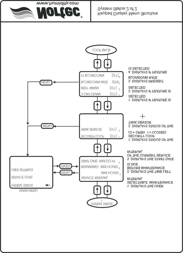
WARNING:
Improper installation, adjustment, alteration, service or maintenance
can cause injury or property damage. For assistance or additional
information consult a qualified installer or a service agency.
Table Of Contents

GENERAL                                                                                                    1
- RECEIVING & UNPACKING EQUIPMENT. . . . . . . . . . . . . . . . . . . . . . . . . . . . . . . . 1
- DELIVERY . . . . . . . . . . . . . . . . . . . . . . . . . . . . . . . . . . . . . . . . . . . . . . . . 1
- GENERAL SPECIFICATIONS . . . . . . . . . . . . . . . . . . . . . . . . . . . . . . . . . . . . . . 1
- MODEL DESIGNATION . . . . . . . . . . . . . . . . . . . . . . . . . . . . . . . . . . . . . . . . . 1
MODEL CAPACITY & PHYSICAL DATA                                                                          2-7
FLOOR STAND                                                                                                8
CEILING MOUNTING INSTALLATION                                                                              9
TYPICAL SE INSTALLATION DIAGRAM                                                                          10
SETC OUTDOOR DIMENSIONS                                                                                  11
ROOF CURB DIMENSIONS                                                                                     12
SE INDOOR INSTALLATION                                                                                   13
- LOCATING AND MOUNTING . . . . . . . . . . . . . . . . . . . . . . . . . . . . . . . . . . . . . . 13
- PRIMARY WIRING . . . . . . . . . . . . . . . . . . . . . . . . . . . . . . . . . . . . . . . . . . . 13
- ELECTRICAL . . . . . . . . . . . . . . . . . . . . . . . . . . . . . . . . . . . . . . . . . . . . . . 14
- LOW VOLTAGE CONTROL WIRING . . . . . . . . . . . . . . . . . . . . . . . . . . . . . . . . . 14
- CONTROL INSTALLATION . . . . . . . . . . . . . . . . . . . . . . . . . . . . . . . . . . . . . . . 17
- PLUMBING . . . . . . . . . . . . . . . . . . . . . . . . . . . . . . . . . . . . . . . . . . . . . . . 17
- WATER QUALITY . . . . . . . . . . . . . . . . . . . . . . . . . . . . . . . . . . . . . . . . . . . . 17
- FILL WATER SUPPLY LINE . . . . . . . . . . . . . . . . . . . . . . . . . . . . . . . . . . . . . . 17
- DRAIN LINE . . . . . . . . . . . . . . . . . . . . . . . . . . . . . . . . . . . . . . . . . . . . . . . 18
- STEAM CONDENSATE OUTLET . . . . . . . . . . . . . . . . . . . . . . . . . . . . . . . . . . . . 18
- AUXILIARY DRAIN OUTLET . . . . . . . . . . . . . . . . . . . . . . . . . . . . . . . . . . . . . . 18
- STEAM LINES AND CONDENSATE LINE . . . . . . . . . . . . . . . . . . . . . . . . . . . . . . . 18
- PRESSURIZED STEAM CONNECTIONS . . . . . . . . . . . . . . . . . . . . . . . . . . . . . . . 18
- STEAM SUPPLY PIPING . . . . . . . . . . . . . . . . . . . . . . . . . . . . . . . . . . . . . . . . 18
ACTUATOR INSTALLATION                                                                                    19
- WHAT COMES WITH THE ACTUATOR . . . . . . . . . . . . . . . . . . . . . . . . . . . . . . . . 19
- INSTALLATION INSTRUCTIONS . . . . . . . . . . . . . . . . . . . . . . . . . . . . . . . . . . . . 19
- PRE-LOADING INSTRUCTIONS . . . . . . . . . . . . . . . . . . . . . . . . . . . . . . . . . . . . 19
SETC OUTDOOR INSTALLATION                                                                                21
- MOUNTING . . . . . . . . . . . . . . . . . . . . . . . . . . . . . . . . . . . . . . . . . . . . . . . 21
- PRESSURIZED STEAM SUPPLY . . . . . . . . . . . . . . . . . . . . . . . . . . . . . . . . . . . 21
- ELECTRICAL INSTALLATION . . . . . . . . . . . . . . . . . . . . . . . . . . . . . . . . . . . . . 21
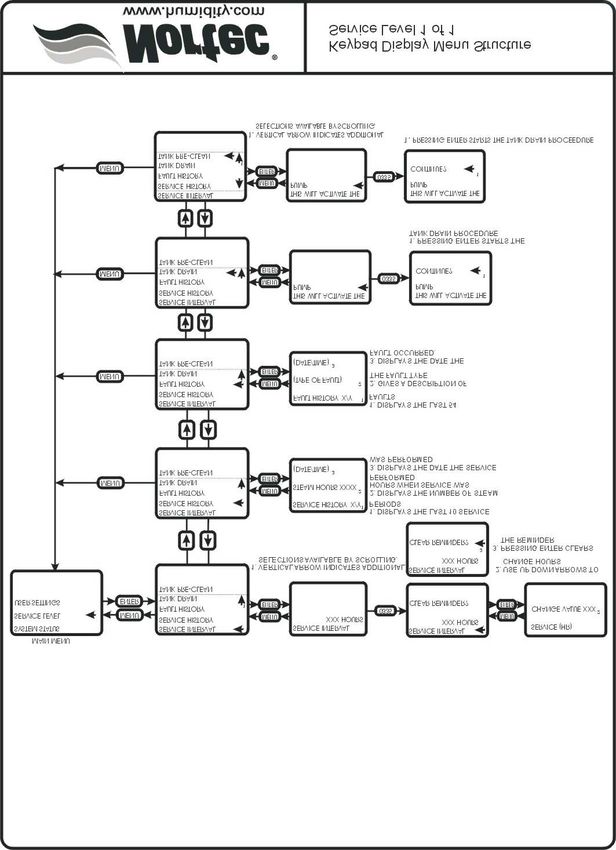
- FILL WATER SUPPLY LINE . . . . . . . . . . . . . . . . . . . . . . . . . . . . . . . . . . . . . . 23
- DRAIN LINE . . . . . . . . . . . . . . . . . . . . . . . . . . . . . . . . . . . . . . . . . . . . . . . 23
- AUX DRAIN . . . . . . . . . . . . . . . . . . . . . . . . . . . . . . . . . . . . . . . . . . . . . . . 23
- STEAM LINES . . . . . . . . . . . . . . . . . . . . . . . . . . . . . . . . . . . . . . . . . . . . . . 23
OPERATION                                                                                                 23
- WATER MANAGEMENT . . . . . . . . . . . . . . . . . . . . . . . . . . . . . . . . . . . . . . . . 23
INSPECTION AND START-UP PROCEDURE                                                                         24
- START UP PROCEDURE . . . . . . . . . . . . . . . . . . . . . . . . . . . . . . . . . . . . . . . 24
- FILLING THE SYSTEM . . . . . . . . . . . . . . . . . . . . . . . . . . . . . . . . . . . . . . . . . 24
- STARTING THE HUMIDIFIER . . . . . . . . . . . . . . . . . . . . . . . . . . . . . . . . . . . . . 24
- TAKING OUT OF OPERATION . . . . . . . . . . . . . . . . . . . . . . . . . . . . . . . . . . . . . 25
- SE INSPECTION CHECK LIST . . . . . . . . . . . . . . . . . . . . . . . . . . . . . . . . . . . 26-27
SCALE MANAGEMENT                                                                                          28
- WATER QUALITY . . . . . . . . . . . . . . . . . . . . . . . . . . . . . . . . . . . . . . . . . . . . 28
MAINTENANCE                                                                                               29
- DRAINING THE TANK . . . . . . . . . . . . . . . . . . . . . . . . . . . . . . . . . . . . . . . . . 29
- CLEANING THE STAINLESS STEEL TANK & FLOAT CHAMBER . . . . . . . . . . . . . . . . . . 29
- ADJUSTMENTS/REPLACEMENTS OF COMPONENTS . . . . . . . . . . . . . . . . . . . . . . . . 30
- SERVICING THE UNIT . . . . . . . . . . . . . . . . . . . . . . . . . . . . . . . . . . . . . . . . . 30
- TRANSFORMER REPLACEMENT . . . . . . . . . . . . . . . . . . . . . . . . . . . . . . . . . . . 31
- FILL VALVE REPLACEMENT . . . . . . . . . . . . . . . . . . . . . . . . . . . . . . . . . . . . . . 31
- DRAIN PUMP REPLACEMENT . . . . . . . . . . . . . . . . . . . . . . . . . . . . . . . . . . . . . 31
- FILL BOX REPLACEMENT . . . . . . . . . . . . . . . . . . . . . . . . . . . . . . . . . . . . . . . 32
- REMOVAL OF HEAT EXCHANGER . . . . . . . . . . . . . . . . . . . . . . . . . . . . . . . . . . 32
- FAULT CONDITIONS . . . . . . . . . . . . . . . . . . . . . . . . . . . . . . . . . . . . . . . . . . 32
- SETC SETTINGS . . . . . . . . . . . . . . . . . . . . . . . . . . . . . . . . . . . . . . . . . . 33-34
- SETC LOGIC CONTROL BOARD . . . . . . . . . . . . . . . . . . . . . . . . . . . . . . . . . . . 35
- KEYPAD DISPLAY MENU STRUCTURE . . . . . . . . . . . . . . . . . . . . . . . . . . . . . . 36-41
- NORTEC TC CONTROLLER . . . . . . . . . . . . . . . . . . . . . . . . . . . . . . . . . . . . . . 42
- FAULT AND WARNING LIST . . . . . . . . . . . . . . . . . . . . . . . . . . . . . . . . . . . . . . 52
- MANDATORY MAINTENANCE SCHEDULE . . . . . . . . . . . . . . . . . . . . . . . . . . . . . . 53
- SETC INTERNAL WIRING DIAGRAM . . . . . . . . . . . . . . . . . . . . . . . . . . . . . . . . . 54
- SEP INTERNAL WIRING DIAGRAM . . . . . . . . . . . . . . . . . . . . . . . . . . . . . . . . . . 55
- SE SERIES SPARE PARTS          . . . . . . . . . . . . . . . . . . . . . . . . . . . . . . . . . . . . 56-63
GENERAL                                                  GENERAL SPECIFICATIONS

     This installation guide has been designed to                  The NORTEC SE Series humidifier is a completely
provide assistance when installing, mounting, and              new design based on leading edge technology. The
sizing a SE Series humidifier. Actual on site                  SE is designed to provide clean atmospheric steam at
application may vary. Consult Walter Meier (Nortec)            an economical price.
Technical Services or your local Walter Meier (Nortec)
representative.

                                                                                MODEL DESIGNATION
 RECEIVING & UNPACKING EQUIPMENT
                                                                   The unit specification label indicates the model of
    1. Check packing slip to ensure ALL material has           Steam Exchange humidifier according to the following
       been delivered.                                         chart:
    2. All material shortages are to be reported to
       Walter Meier (Nortec) within 48 hours from
       receipt of goods. Walter Meier (Nortec)                                                         SE   TC   100   OC
       assumes no responsibility for any material
       shortages beyond this period.                              PRODUCT LINE
                                                                  (Steam Exchange Humidifier)

    3. Inspect shipping boxes for damage and note                 TC = Total Controller
                                                                        c/w KEYPAD
       on shipping waybill accordingly.                           P = Economical
                                                                                                50
                                                                  Humidifier size               100
    4. After unpacking, inspect equipment for                                                   175
                                                                                                250
       damage and if damage is found, notify the                                                375
                                                                                                475
       shipper promptly.                                                                        675
                                                                                                950
                                                                                                1050
    5. All Walter Meier (Nortec) products are shipped             Outdoor

       on an F.O.B. factory basis. Any and all
       damage, breakage or loss claims are to be
       made directly to the shipping company.

                     DELIVERY

The standard delivery includes:

    1. Steam Exchange humidifier equipped with
       desired options.

    2. In a bag you will find:

        - Manuals.
        - Plastic adapter for potable, RO, DI or
          softened water connection.
        - Steam hose for steam outlet with clamps.

    3. The SE Series comes complete with a
       telescopic stand mounted inside the unit legs.
       Stand cross bracing is shipped with the unit.
       (Optional on SE 50).

    4. Steam valve, actuator, and wye strainer.

    5. Desired accessories ordered.

                                                         -1-
MODEL CAPACITY & PHYSICAL DATA
                                                          Table #1

                                                           Operating Steam Pressure
    SETC/SEP
                      5 psi (34kpa)       7 psi (48kpa)           10 psi (69 kpa)     13 psi (90 kpa)   15 psi (103 kpa)
                                                                  Lbs/hr (kg/hr)
      SE 50               17 (8)              20 (9)                  28 (13)            40 (18)            50 (23)
      SE 100             33 (15)             41 (19)                  58 (26)            80 (36)           100 (45)
      SE 175             45 (20)             59 (27)                  88 (40)            131 (59)          175 (79)
      SE 250             77 (35)             98 (44)                 140 (64)            200 (91)          250 (113)
      SE 375             105 (48)           136 (62)                 200 (91)           294 (133)          375 (170)
      SE 475             161 (73)           201 (91)                 279 (127)          388 (176)          475 (215)
      SE 675             200 (91)           256 (116)                368 (167)          531 (241)          675 (306)
      SE 950            386 (175)           463 (210)                609 (276)          800 (363)          950 (431)
     SE 1050            446 (202)           529 (240)                682 (309)          880 (399)         1050 (476)
NOTE: Specification subject to change without notice. Rated capacity applies with no blowdown.

        .

                                                            -2-
1 1/2"
3.8 cm 7/8"
FASTENING POINTS 2.3 cm 8 3/4"
1 13/16" 14 1/2" FOR CEILING MOUNT 22.3 cm
46.3mm 36.9 cm
POWER AND CONTROL
BOTTOM PORT
12 13/16"
32.6 cm
1 7/16"
RIGHT
3.7 cm
POWER AND CONTROL
SUPPLY WATER
3/4 BSPP MALE OR
1/2 NPT MALE
2 1/4"
5.8 cm
FRONT
1 9/16"
18 3/8" 4.0 cm
46.7 cm
8 1/4"
STEAM OUTLET 21.0 cm 2 11/16"
25 5/8" 4 9/16"
65.1 cm 1 3/4" O.D TUBE 6.9 cm
11.6 cm
8"
20.3 cm
1"
2.6 cm 10 5/16"
26.2 cm
16 3/4"
20 5/8" 42.6 cm
52.4 cm
7/8 TUBE, DRAIN
BOILER STEAM IN
1 1/16" 19 9/16"
1/2 NPT MALE 2.8 cm 49.7 cm
1 3/8"
3.5 cm
2 9/16"
6.5 cm
3/4 NPT MALE
CONDENSATE OUT
AUXILIARY DRAIN/
CONDENSATE RETURN
TO UNIT 1/2 NPT FEMALE
SERVICE CLEARANCE TECHNICAL DATA SE 50
TOP 0” 0 cm Max. Rated Steam 56 lb/hr 25.4 kg/hr
LEFT 0” 0 cm Nominal @ 5 psi 3-17 lb/hr 1.4-7.7 kg/hr
RIGHT 30" 76 cm Nominal @ 10 psi 6-28 lb/hr 2.7- 12.7 kg/hr
REAR 0” 0 cm Nominal @ 15 psi 10-50 lb/hr 4.5-22.6 kg/hr
FRONT 30" 76 cm Steam Valve CV 2.2
BOTTOM 0” 0 cm Supply Water Con. ½” NPT or ¾” BSPP male
Drain Water Connection 0.825” (2.1 cm) tube
Aux. Drain Con. ½” NPT female
Pressure Steam In ½” NPT male
Steam Cond. Out ¾” NPT male
Atm. Steam Out 1 x 1.75 OD (4.5 cm)
Weight Empty 125 lb 57 kg
Weight Full 180 lb 82 kg
Physical Data
SETC / SEP 50
3/27/06
-3-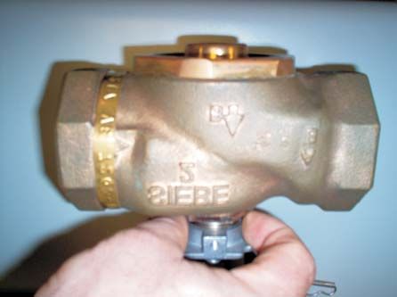
TOP
13.9" STEAM OUTLET
( 35.2cm )
5.5"
( 13.9cm )
20.8"
( 53cm )
3.5" FRONT
( 9cm )
RIGHT SIDE
1.5" 1.0"
CONTROL SIGNAL ( 2.5cm )
( 3.9cm )
1.9"
( 4.83cm )
2.5"
44.5" ( 6.4cm )
( 113.2cm ) PRESSURE
STEAM INLET 3.7"
( 9.47cm )
7.4"
WATER INLET ( 18.92cm )
10.3"
( 26.2cm )
CONTROL PANEL
31.6"
( 80.3cm )
DRAIN
STEAM
CONDENSATE OUTLET
AUX. DRAIN
6.8"
( 17.18cm )
4.0" 2.0" 4.1"
( 10.2cm ) 9.7" ( 5.1cm ) ( 10.3cm )
POWER SUPPLY ( 24.6cm )
21.0" 1.0"
( 53.3cm ) 16.1" ( 2.5cm )
( 40.8cm )
40.2"
( 102.2cm )
SERVICE CLEARANCE Technical data SE 100 SE 175
TOP 36” 91 cm Max.Rated Steam 105 lb/hr 48 kg/hr 180 lb/hr 82 kg/hr
LEFT 0” 0 cm Nominal @ 5psi 5-33 lb/hr 2-15 kg/hr 7-45 lb/hr 3-20 kg/hr
RIGHT 30" 76 cm
Nominal @10psi 9-58 lb/hr 4-26 kg/hr 13-88 lb/hr 6-40 kg/hr
REAR 0” 0 cm
Nominal @15psi 15-100 lb/hr 7-45 kg/hr 26-175 lb/hr 12-79 kg/hr
FRONT 30" 76 cm
BOTTOM 0” 0 cm Steam Valve CV 2.8 7.5
Supply water con. 0.5” NPT 0.5” NPT
Drain water con. 0.75” O.D. tube 0.75” O.D. tube
Aux. drain con. 0.5” NPT female 0.5” NPT female
Pressure steam in. 0.5” NPT 0.5” NPT
Steam Cond. Out. .75" NPT .75" NPT
Atm. Steam Out. 1 x 1.75” OD 1 x 4.4 cm OD 1 x 3.00” OD 1 x 7.62cm OD
Weight Empty 267 lb 121 kg 267 lb 121kg
Weight Full 423 lb 192 kg 423 lb 192 kg
Physical Data
SETC 100 - 175
5/4/07
-4-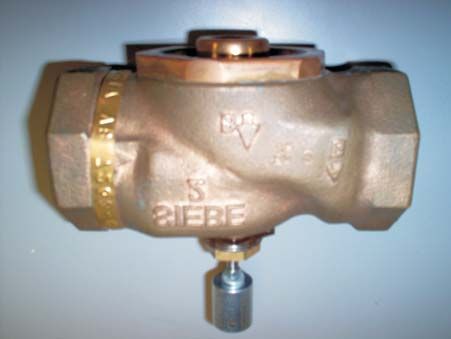
TOP
13.9" STEAM OUTLET
( 35.2cm )
5.5"
( 13.9cm )
27.2"
( 69cm )
3.5"
( 9cm )
FRONT
RIGHT SIDE
1.0"
( 2.6cm )
CONTROL SIGNAL 1.5"
( 3.9cm ) 1.9"
( 4.8cm )
2.5"
44.6" PRESSURE ( 6.4cm )
( 113.3cm ) STEAM INLET 3.7"
( 9.5cm )
7.4"
WATER INLET ( 18.9cm ) 10.3"
( 26.2cm )
CONTROL PANEL
31.6"
( 80.3cm )
DRAIN
STEAM
CONDENSATE OUTLET
AUX. DRAIN
6.8"
( 17.2cm )
4.1"
4.0" 9.7" ( 10.3cm )
( 10.2cm ) ( 24.6cm ) 2.0"
POWER SUPPLY 22.4" ( 5.1cm )
21.0" ( 56.8cm ) 1.0"
( 53.3cm ) ( 2.5cm )
40.2"
( 102.2cm )
SERVICE CLEARANCE Technical data SE 250 SE 375
TOP 36” 91 cm
LEFT 0” 0 cm
Max.Rated Steam 255 lb/hr 115 kg/hr 380 lb/hr 172 kg/hr
RIGHT 30" 76 cm Nominal @ 5psi 11-77 lb/hr 5-35 kg/hr 15-105 lb/hr 7-47 kg/hr
REAR 0” 0 cm Nominal @10psi 21-140 lb/hr 10-64 kg/hr 30-200 lb/hr 14-91 kg/hr
FRONT 30" 76 cm Nominal @15psi 37-250 lb/hr 17-114 kg/hr 56-375 lb/hr 25-170 kg/hr
BOTTOM 0” 0 cm Steam Valve 12 28
Supply water con. 0.5” NPT 0.5” NPT
Drain water con. 0.75” O.D. tube 0.75” O.D. tube
Aux. drain con. 0.5” NPT female 0.5” NPT female
Pressure steam in. 1.0” NPT 1” NPT
Steam Cond. Out. .75” NPT .75” NPT
Atm. Steam Out. 1 x 3” OD 1 x 7.62 cm OD 1 x 4” OD 1 x 10.2cm OD
Weight Empty 355 lb 161 kg 355 lb 161 kg
Weight Full 599 lb 272 kg 599 lb 272 kg
Physical Data
SETC 250 - 375
5/4/07
-5-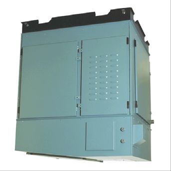
TOP
13.7"
( 34.9cm )
STEAM OUTLET
5.5"
( 13.9cm )
FRONT
42.7"
( 108.6cm )
RIGHT SIDE
3.5"
( 9cm )
1.0"
( 2.5cm )
1.9"
1.5" ( 4.8cm )
CONTROL SIGNAL 2.5"
( 3.9cm ) PRESSURE ( 6.4cm )
STEAM INLET
3.7"
( 9.5cm ) 7.4"
WATER INLET ( 18.9cm ) 10.3"
( 26.2cm )
CONTROL PANEL
31.6" DRAIN
( 80.3cm )
STEAM
CONDENSATE OUTLET
AUX. DRAIN
6.8"
( 17.2cm )
4.0" 9.7" 4.1"
( 10.2cm ) ( 24.6cm ) ( 10.3cm )
2.0"
21.0" 21.9" ( 5.1cm )
( 53.3cm ) ( 55.5cm ) 1.0"
40.2" POWER SUPPLY ( 2.5cm )
( 102.2cm ) 38.0"
( 96.4cm )
SERVICE CLEARANCE Technical data SE 475 SE 675
TOP 36” 91 cm
Max.Rated Steam 480 lb/hr 217 kg/hr 680 lb/hr 308 kg/hr
LEFT 30" 76 cm
Nominal @ 5psi 24-161 lb/hr 11-73 kg/hr 30-200 lb/hr 14-91 kg/hr
RIGHT 30" 76 cm
REAR 0” 0 cm Nominal @10psi 42-279 lb/hr 19-127kg/hr 55-368 lb/hr 25-167 kg/hr
FRONT 30" 76 cm Nominal @15psi 71-475 lb/hr 32-215 kg/hr 101-675 lb/hr 46-306 kg/hr
BOTTOM 0” 0 cm Steam Valve CV 20 28
Supply water con. 0.5” NPT 0.5” NPT
Drain water con. 0.75” O.D. tube 0.75” O.D. tube
Aux. drain con. 0.5” NPT female 0.5” NPT female
Pressure steam in. 1.25 ” NPT 1.5” NPT
Steam Cond. Out. 1.0” NPT 1.0” NPT
Atm. Steam Out. 1 x 4” OD 1 x 10.16cm OD 1 x 4” OD 1 x 10.16cm OD
Weight Empty 529 lb 240 kg 529 lb 240 kg
Weight Full 992 lb 450 kg 992 lb 450 kg
Physical Data
SETC 475 - 675
5/4/07
-6-39.5"
( 100.2cm ) PRESSURE STEAM INLET
9.9" 8.0" TOP
( 25cm ) ( 20.3cm )
5.5" 5.3"
( 13.9cm ) ( 13.6cm )
STEAM
OUTLETS
58.3"
( 148.2cm )
CONTROL SIGNAL
FRONT
RIGHT SIDE
3.5"
( 9cm )
1.0"
( 2.5cm )
2.5"
1.5" WATER INLET ( 6.4cm )
( 3.9cm )
7.4"
( 18.9cm ) 10.3"
DRAIN ( 26.2cm )
31.6" CONTROL PANEL
STEAM CONDENSATE
( 80.3cm ) OUTLET
2.0"
( 5.1cm )
AUX. DRAIN
6.8"
4.1" ( 17.2cm )
( 10.3cm )
9.7"
4.0" ( 24.6cm ) 1.0"
( 10.2cm ) 29.7" ( 2.5cm )
21.0" POWER SUPPLY ( 75.3cm )
( 53.3cm ) 53.6"
( 136.1cm )
40.2"
( 102.2cm )
SERVICE CLEARANCE Technical data SE 950 SE 1050
TOP 36” 91 cm
Max.Rated Steam 960 lb/hr 435 kg/hr 1070 lb/hr 485 kg/hr
LEFT 30" 76 cm
RIGHT 30" 76 cm
Nominal @ 5psi 58-386 lb/hr 26-175 kg/hr 67-446 lb/hr 30-202 kg/hr
REAR 0” 0 cm Nominal @10psi 91-609 lb/hr 41-276 kg/hr 102-682 lb/hr 46-309 kg/hr
FRONT 30" 76 cm Nominal @15psi 142-950 lb/hr 64-430 kg/hr 158-1050 lb/hr 72-476 kg/hr
BOTTOM 0” 0 cm Steam Valve CV 40 65
Supply water con. 0.5” NPT 0.5” NPT
Drain water con. 0.75” O.D. tube 0.75” O.D. tube
Aux. drain con. 0.5” NPT female 0.5” NPT female
Pressure steam in. 2.0” NPT 2.5” NPT
Steam Cond. Out. 1.25” NPT 1.25” NPT
Atm. Steam Out. 2 x 4” OD 2 x 10.16cm OD 2 x 4” OD 2 x 10.16cm OD
Weight Empty 703 lb 319 kg 703 lb 319 kg
Weight Full 1384 lb 628 kg 1384 lb 628 kg
Physical Data
SETC 950 - 1050
5/4/07
-7--8-
NOTES:
   1. UNIT WEIGHT WITH WATER = 180 LB. THIS DOES NOT INCLUDE THE ADDITIONAL PLUMBING NEEDED
   FOR CONNECTION. TOTAL WEIGHT MUST BE DETERMINED BY OTHERS.
   2. STRUCTURAL CONSIDERATIONS ARE THE RESPONSIBILITY OF OTHERS.
   3. PROPER MOUNTING MEANS, SUCH AS; THE SECURING OF FASTENERS OR OTHER JOINTS, IS THE
   RESPONSIBILITY OF OTHERS.
   4. UNIT CANNOT BE USED AS A STRUCTURAL MEMBER. NO OTHER COMPONENTS MAY BE ATTACHED TO
   IT.
   5. SERVICE ACCESS IS REQUIRED AT THE FRONT AND RIGHT SIDE OF THE UNIT. A MINIMUM OF
   30” (76 cm) CLEARANCE IS NEEDED.
   6. SIZES AND FEATURE LOCATIONS ARE TO BE DERIVED FROM THE UNIT DIMENSIONAL DRAWINGS OR
   BY CONSULTING THE FACTORY.

                                                        SECURE RODS
                                                    TO STABLE STRUCTURE
UPPER BRACING BRACKET
        RECOMMENDED

                                                           THREADED ROD
                                                      3/8" OR METRIC M10

                                                    SLIDE UNIT ONTO RODS
                                                    THROUGH HOLES PROVIDED

                                         SLIDE FACTORY SUPPLIED
                                        BOTTOM BRACKETS IN PLACE

                      IF USING FACTORY HARDWARE, RODS CAN
              ONLY EXTEND 1" PAST THE BOTTOM OF THE CABINET

    SECURE BRACKETS TO RODS. PROPER INSTALLATION MEANS MUST BE
             USED TO ENSURE THAT THE ASSEMBLY DOES NOT DETACH

   IF USING FACTORY DRIP PAN, FASTENING HARDWARE MUST BE CONCEALED
                           WITHIN THE PROFILE OF THE BOTTOM BRACKETS

           ATTACH DRIP PAN. SECURE TO BOTTOM BRACKETS VIA END SCREW ATTACHMENT

                  DO NOT DRAIN UNIT INTO DRIP PAN. DO NOT ROUTE ANY OTHER FLUID TO DRIP PAN.
     DRIP PAN IS NOT A STRUCTURAL MEMBER AND CANNOT BE USED TO SUPPORT OTHER ELEMENTS

                                                  1/2 NPT PLUMBING OR EQUIVALENT IS RECOMMENDED
                                                                              TERMINATE AT DRAIN

                                                             SE 50
                                                             Ceiling Mounting Installation (Optional)
                                                             3/27/06

                                                       -9-
Short-Absorption Manifold (SAM-e)
Duct or AHU Stainless steel
steam tubes Typical SE Installation
SAM-e (Short Absoption Manifold)
Can be installed in the Horizontal
duct or vertical Duct or a AHU.
Reference SAM-e Installtion 1. This drawing is for reference only. Installation
Manual must conform to all local codes.
Galvanized Mounting Frame
2. Refer to physical data drawings for dimensions.
Optional
Copper or S.S.
6" Long hose cuff for 1.75" dia. tubing pipe - 1" Insulation
4" long hose cuff for 3" & 4" dia. tubing Recommanded
Water supply
and 2 gear clamps for steam line connection.
30 to 80 psig
(By Nortec) 6" Long hose cuff and 2 gear
clamps for steam line connection. Pressurized steam connection from Boiler
12"
2" (by Nortec) Max. 15 psi
Min. 5 psi
6 " Min
Stainless Steel
Steam Header 3/4" NPT Condensate
Return
Controls (By Nortec or by Others)
Union
(by Others)
6" min., P-Trap must be 2" more than Steam Valve and Actuator must be located 6" max.
duct static pressure from the SE humidifier.
Inlet located on top of unit for SE models 475 to 1050.
- 10 -
Valve and Actuator must be installed horizontally.
Refer to the Invensys installation manual for details.
Condensate Return 6 " Min
to drain or sump pump Wye strainer (By Nortec)
Steam trap (By Nortec or by Others)
Return to nonpressurized system,
Primary wire and by gravity only
disconnect (By Others) 1/2" NPT Supply water
connection. (Manual shut-off
valve by Others)
3/4" O.D. Drain connection
to funnel drain or sump pump
Standard
Telescopic Funnel with 1" air gap 1/2" NPT Aux. Drain, Optional
Stand supplied by others Plugged at factory
(Option by (Shut-off valve by Others)
Nortec)
Open floor drain must be properly sized
Drain water cooler and and rated for maximum temperature requirements.
F & T Steam trap(s)
Located inside unit. Installed Steam condensate drain.
at Nortec Return to nonpressurized system,
by gravity only
Typical SE Installation10”
A (258mm)
*Required for
12”
(30.5 cm)
SETC Outdoor
475-1050
(126.2 cm)
49.7”
(101.6 cm)
CLEARANCE
ENVELOPE
40”
FRONT
RIGHT 30”
(76.2 cm)
TOP
NEMA RATED
JUNCTION BOX
*Cleaning Port for (By Others)
SETC Outdoor 475-1050 Power and
Controls
Vent Steam
Hood Outlet(s)
(138 cm)
54.3”
Cleaning
Port
BACK
LEFT
FRONT RIGHT
Shipped Operating
Steam Outlet Pressure Steam Steam Condensate
A
Model Weight Weight (O.D.) Inlet Outlet
in cm lbs kg lbs kg in cm NPT NPT
SETC Outdoor 100 1x1.75 1x4.4 0.5
21.5 54.6 267 121 423 192 0.75
SETC Outdoor 175 1x3 1x7.6 0.75
SETC Outdoor 250 1x3 1x7.6 1
27.9 70.8 355 161 599 272 0.75
SETC Outdoor 375 1x4 1x10.2 1.5
SETC Outdoor 475 1.25
43.5 111 529 240 992 450 1x4 1x10.2 1
SETC Outdoor 675 1.5
SETC Outdoor 950 2
59.1 150 703 319 1384 628 2x4 2x10.2 1.25
SETC Outdoor 1050 2.5
SETC Outdoor Dimensions
1/26/04
- 11 -- 12 -
· Ambient temperature location for humidifier:
   SE INDOOR INSTALLATION                                              41ºF - 104ºF (5ºC - 40ºC).

         LOCATING AND MOUNTING                                       · Relative humidity location for humidifiers:
                                                                       5% rh - 80% rh.
    SE Series humidifiers are designed to mount on
an SE Stand (Included with all models) or floor. The                 · DO NOT mount humidifier on hot surfaces.
clearance dimensions shown in this manual are for
reference only and are the minimum required for                      · DO NOT mount humidifiers in an area where
maintenance of the humidifier. Local and National                      freezing may occur.
Codes should be consulted prior to final location and
installation of the humidifier. NORTEC cannot accept                 · If humidifiers are mounted on roof, a properly
responsibility for installation code violations.                       ventilated, temperature controlled, (above
                                                                       freezing), weatherproof model should be used.
  · Figure #1 shows the locations of all required                      Consult your local representative for more
    connections to the Steam Exchange Humidifier.                      information on NORTEC’s SETC Outdoor model.
    Careful consideration should be given to all of
    these connections when choosing a location for                   · DO NOT mount humidifiers on vibrating surface.
    the humidifier.                                                    Consult factory.

  · For front and side clearance requirements (for                   · The humidifier shall not be installed directly on
    access during installation, maintenance and                        carpeting, tile or other combustible material other
    troubleshooting), refer to pages 3 - 6.                            than wood flooring.

  · DO NOT locate humidifier any further than                        · Some insulating materials may be combustible.
    absolutely necessary from steam distributor                        Prior to installing this appliance examine the area
    location. Net output will be reduced as a result of                for insulating material. If this appliance is
    heat loss through steam line. Also, increased                      installed in an insulated space, it must be kept
    static pressure (over 12" W.C.) will result in hot                 free and clear of insulating materials. If insulation
    water going down the drain. Consult factory if this                is added after the appliance is installed, it will be
    situation occurs.                                                  necessary to examine the area again.

  · Where possible, mount humidifier at a height                   PRIMARY WIRING
    convenient for servicing.
                                                                          All work concerning the electrical installation
  · Ensure the humidifier is mounted level.                        must be performed by qualified personnel.

                                                     Figure #1
                                            Primary Wiring to Humidifier

                                                          - 13 -
ELECTRICAL summary of the common types of controls that may be
used with NORTEC SE Humidifiers.
WARNING: The electrical parts inside the
humidifier are very sensitive to electrostatic discharge. A – Wall or Duct Mounted Control On/Off
Appropriate measures against electrostatic discharge Humidistat: Wired to make on drop in humidity, break
(ESD protection) must be taken when carrying out on rise to set point. Set to desired RH. Can be a
installation work. make/break set of contacts from a Building
Management System.
· The humidifier should only be connected to
B – Duct Mounted Safety High Limit On/Off
primary power (main power) after all installation
Humidistat: Wired to make on drop in humidity, break
work has been completed.
on rise to safety set point. Set to approximately 85%
RH as a safety to prevent saturation and wetting in the
· An external disconnect switch(by others) must be duct. Highly recommended for ducted applications.
installed close to the unit to allow for power
interruption during servicing and/or maintenance. C – Duct Mounted Safety Air Proving On/Off
Switch: Wired to make when sensing air flow, break
· Humidifiers require field wiring to primary voltage when no air flow. Used as a safety to prevent
terminal blocks. Power requirement must be saturation when there is no air flow. Highly
110-120/1/60Vac, 15A or 20 A for SETC Outdoor recommended for ducted applications.
950 &1050 separately fused circuit, single phase.
Wiring can be fed through a 7/8" hole on the D – Wall or Duct Mounted Modulating Humidistat:
bottom or the top of the control compartment. Provides a modulating signal to the unit that
represents the output (up to 100%) required from the
· When installed, the appliance must be electrically humidifier. Signal type can be changed in the field via
grounded in accordance with local codes or, in dip switch settings on the logic control board. Refer to
the absence of local codes, with the National SETC Setting section.
Electrical Code, ANSI/NFPA 70, and/or the CSA
C22.1 Electrical Code, if an external electrical The SETC can accept a single or dual control
source is utilized. signal. The SEP can only accept a single control
signal:
· External wiring sizes must be in accordance with
NEC and/or CEC and existing local electrical SETC SEP
codes and by-laws.
0-20 mA
LOW VOLTAGE CONTROL WIRING 4-20 mA 4-20 mA
0-10 VDC 0-10 VDC
(See Page 14 for details)
2-10 VDC
All SE models require at least one type of input 0-5 VDC
control signal for unit operation. Refer to the sections 1-5 VDC
below that detail the types of controls that can be used
with each model. ON/OFF ON/OFF
Low voltage control terminal strips are provided in The unit must be ordered from the factory for the
the electrical compartment. Refer to the specific desired signal type and number of channels. If no
control wiring diagram supplied with each unit. signal type was specified, ON/OFF control signal will
be set as default. When configured for 2-channel
Field wiring from humidistat to humidifier and modulation the humidifier will generate steam only if
between devices should be shielded 18 AWG or both channels indicate a demand (see D). If both
heavier and kept as short as possible. channels are demanding steam the humidifier will
satisfy the lower demand signal.
Controls are available from NORTEC as
accessories and can be ordered with the humidifier.
Controls by others may also be used as long as they
meet the criteria noted below. The following is a
- 14 -SETC SERIES
EXTERNAL CONTROLS WIRING CONNECTIONS
LOW VOLTAGE TERMINAL STRIP
NOTE: This is a generic wiring diagram only. For specific wiring instructions, it is necessary to refer
to the wiring diagram which is supplied with each unit.
WA R N I N G : F a i l u r e t o w i r e t h e c o n t r o l l e r i n a c c o r d a n c e w i t h t h e w i r i n g d i a g r a m t h a t w a s s u p p l i e d
w i t h t h e u n i t c o u l d p e r m a n e n t l y d a m a g e t h e S E T C b o a r d . S u c h e r r o r s w i l l v o i d t h e u n i t w a r r a n t y.
Full Tank Blow Down (FTBD)
10 Vdc output (20 mA max.)
Modulation Input Signal “A"
Modulation Input Signal “B”
Security Loop
Safety Interrupt (24 Vac)
Humidifier “SERVICE”
enable (24 Vac)
Humidifier “ACTIVE”
Actuator
Humidifier “FAULT”
Humidifier “ON”
24V (Hot)
Common
Signal
N.O.
N.O.
N.O.
N.O.
COM
COM
COM
COM
N.C.
EXTERNAL EXTERNAL
INTERNAL
1 2 3 4 5 6 7 8 9 10 11 12 13 14 15 16 17 18 19 20 21 INTERNAL
NOTE: If no On/Off Control is used then a field jumper
must be connected across terminals 1 and 2 in order
for the humidifier to operate.
Low Voltage Terminal Strip
1 & 2: Wire all on/off controls and safeties between these two terminals. If not used, jumper 1 & 2 for the
unit to operate.
4: Modulating input to humidifier “A”.
5: Modulating input to humidifier “B”.
6: 10 Vdc output (20 mA max.) Can be used to simulate demand to unit..
8: When 24 Vac input received, the unit will initialize a full tank blowdown.
9: Safety interrupt (24 Vac).
10 & 11: Remote indication connection for humidifier “on” status indication.
12 & 13: Remote indication connection for humidifier “active” status.
14 & 15: Remote indication connection for service required indication.
16,17 & 18: Remote indication connection for fault indication.
19, 20 & 21: Modulating output and 24VAC power to actuator
SETC SERIES
External Controls Wiring Connections
09/16/2004
- 15 -SEP SERIES
EXTERNAL CONTROLS WIRING CONNECTIONS
LOW VOLTAGE TERMINAL STRIP
NOTE: This is a generic wiring diagram only. For specific wiring instructions, it is necessary to refer
to the wiring diagram which is supplied with each unit.
WA R N I N G : F a i l u r e t o w i r e t h e c o n t r o l l e r i n a c c o r d a n c e w i t h t h e w i r i n g d i a g r a m t h a t w a s s u p p l i e d
w i t h t h e u n i t c o u l d p e r m a n e n t l y d a m a g e t h e S E P b o a r d . S u c h e r r o r s w i l l v o i d t h e u n i t w a r r a n t y.
Security Loop
Modulation Input Signal
Actuator
Humidifier “FAULT”
24V (Hot)
Common
Signal
N.O.
COM
N.C.
EXTERNAL EXTERNAL
INTERNAL
1 2 3 4 5 6 7 8 9 10 11 12 INTERNAL
NOTE: If no On/Off Control is used then a field jumper
must be connected across terminals 1 and 2 in order
for the humidifier to operate.
Low Voltage Terminal Strip
1 & 2: Wire all on/off controls and safeties between these two terminals. If not used, jumper 1 & 2 for the
unit to operate.
4: Modulating input to humidifier
5, 6 & 7: Modulating output and 24VAC power to actuator
8, 9 & 10: Remote indication connection for fault indication.
SEP SERIES
External Controls Wiring Connections
09/16/2004
- 16 -CONTROL INSTALLATION · Consider using a water softener. Longer
operating times between tank cleaning will be
· Mount any wall humidistat (control or high limit) achieved with softened water.
over standard electrical box at height similar to
typical thermostat. Any wall humidistat should be · Reverse osmosis (RO) water can provide very
in location representative of overall space being long periods before cleaning is required since it is
humidified and not in path of blower pack or air cleaner than softened water. Deionized (DI)
supply grille. Do not mount on an outside wall water may be used with all models with the
where temperature fluctuations can affect control stainless steel water supply option. Consult your
response. (Windows, sky lights, sinks, coffee NORTEC representative for a quote on a water
machines, etc.) treatment system.
· Mount duct humidistat in location representative FILL WATER SUPPLY LINE
of overall air humidity, usually in return duct. Do
not mount it directly in front of steam distributor or · Each unit is supplied with an adapter for the fill
in turbulent or mixing zone. Mount humidistat valve (½”NPT ). The SE 50-675 has a fill rate of
where air’s humidity and temperature are uniform 10l/min (2.6 gpm) and the SE 950-1050 of
and representative of spaces being humidified. 17l/min (4.5gpm). Size of piping is a minimum ½”
copper, recommend ¾” up to within 4 feet of unit.
· Mount duct high limit humidistat downstream of
steam distributors far enough that, under normal · Standard fill valves are sized for water pressure
humidity and air flow conditions, steam will have ranging from 30 to 80 psig (ideally 55 to 60 psig).
been fully absorbed (typically at least 10 feet). It For other pressures, consult factory. This
must be located to sense high humidity only pressure should be measured at the humidifier if
when uniform and representative air is the water pressure is suspect.
over-humidified or approaching saturation.
· It is recommended to have a faucet installed
· Mount duct air-proving switch so that it is able to close to the humidifier to allow quick filling of the
sense air flow or lack thereof it. Wire it to make system on initial start up. This can also be very
when air flow is sensed and break when air flow useful for mandatory cleaning of the unit.
fails.
· ALWAYS supply and install a shut-off valve and
· Check operation of all on/off controls before union in the water supply line dedicated to the
starting humidifier. humidifier to facilitate servicing.
Figure #2
· Calibration of controls (on/off or modulation) in Installation
the field may be necessary due to shipping and
handling. Verify humidistat accuracy before
commissioning system.
PLUMBING
NOTE: All water supply and drain line
connections should be installed in accordance with
local plumbing codes.
WATER QUALITY
· The humidifier is intended to operate on cold
water.
· DO NOT use a hot water source to supply the
humidifier. Minerals will adhere more easily to
surfaces and the fill valve’s small flow regulating
orifice could become plugged.
- 17 -DRAIN LINE STEAM LINES AND CONDENSATE LINES
· The humidifier is equipped with a ¾”O.D. drain For steam line installation between the humidifier
outlet connection on the side of the humidifier. A and distribution system, consult the distribution system
vacuum break valve is installed internal to the installation manual. Steam Distributor Installation
unit on the drain line. The drain water line must Manual - Form #XX-231 and SAM-e, Short Absorption
be piped to a drain funnel to provide an air gap Manifold - Form #XX-249.
before connection to the building drainage
system. The SE series of Steam Exchange humidifiers can
develop steam pressures up to 12” w.c. to overcome
· The drain line should not end in a sink used duct and steam line pressures. An enclosed trap on
frequently by personnel, or where plumbing the drain line prevents steam from going to drain.
codes prohibit it. Route to a floor drain or Duct pressures above 12” will cause steam to exit
equivalent for safety reasons. Internal drain water through the drain line. Consult factory.
tempering will ensure a maximum of 140ºF
(60ºC) exiting water temperature. PRESSURIZED STEAM CONNECTIONS
· Keep drain lines as short as possible. Keep drain Proper design and sizing of steam supply lines
lines sloped down, not level and not up since low should be preformed by a qualified firm.
spots in drain lines will accumulate sediment and
cause backup. The drain line should be 1-1.5" STEAM SUPPLY PIPING
O.D. or larger. Consult local codes.
The steam valve, actuator, wye strainer, and
· When the drain pump is activated, the tank drains shut-off valve should be installed by a qualified
at a rate of 7-8 gal/min (18-20 l/min). technician.
STEAM CONDENSATE OUTLET Steam supply to the unit must be taken from the
top of the supply main. Do not take from the sides or
MODEL OUTLET the bottom. The steam shut-off valve (supplied by
others) should be installed on the supply line at the
SE 50, 100, 175, 250 and 375 ¾” NPT unit, followed by the wye strainer.
SE 475, and 675 1” NPT The steam valve and Actuator must be located as
close as possible to the humidifier. Further than 6”
SE 950, and 1050 1 ¼” NPT (15cm) away may result in lower output.
· The SE humidifier has a condensate return line
connection for removal of the condensate
formed in the heat exchange.
· Condensate line after the steam trap(s) must be
atmospheric and lower than the traps at all times.
If required, a condensate pump (by others) can
be used to return condensate to the humidifier.
AUXILIARY DRAIN OUTLET
· An auxiliary drain port is also provided on the
side of the humidifier. It can be used to manually
drain the unit, if required. The unit is shipped
with this connection plugged. It is recommended
to install a shut off valve on this line.
· The auxiliary drain port is used when the freeze
protection option is required. Install a shut off
valve on this line and pipe to the drain funnel.
The manual shut off valve must always be in the
open position when the unit is operating but can
be closed for servicing of the unit.
- 18 -ACTUATOR INSTALLATION 3. Thread the stem extension on to the valve
stem making contact with the lock washer.
WHAT COMES WITH THE ACTUATOR
4. Pre-load the actuator
1. Jam Nut
PRE-LOADING INSTRUCTIONS
2. Lock Washer
1. Inserting the hex wrench as illustrated and
3. Stem Extension cranking 1 ½ turns in the direction shown on
the actuator. Lock it into position with the
4. Connecting Pin locking mechanism using a slotted
screwdriver.
5. Set Screw
Figure #5
Figure #3 Pre-loading Instructions
Actuator Parts
2. Install the actuator on the valve and tighten
INSTALLATION INSTRUCTIONS the mounting nut and raise the valve stem to
the full up position.
1. Thread jam nut on to the valve stem as far as
it will go. At least ½” of the valve stem should Figure #6
extend above the nut. Pre-loading Instructions
2. Place lock washer over the valve stem so it is
seated on the jam nut.
Figure #4
Installation Instructions
3. Rotate the stem extension until it’s hole lines
up with the hole in the shaft of the actuator.
- 19 -4. Insert connecting pin to secure stem extension
and tighten jam nut against stem extension
using 5/16” open-end wrench.
5. Affix open/closed label to the indicator in the
appropriate position.
6. Insert set screw (packaged with actuator) into
the most accessible side. Tighten with size 10
IP Torx bit to 20-25 lb-in.
7. Apply power to the actuator and check the
system operation (steam output) in relation to
the control signal.
Figure #7
Pre-loading Instructions
- 20 -louvered panels are a minimum of 10 ft (3m)
SETC OUTDOOR from any mechanical exhaust outlet.
INSTALLATION
· When mounted on the curb, the lowest air intake
SETC Outdoor units come complete with internal louvers must be a minimum of 12” (30.5cm)
ventilation (cooling) for the electronics, and optional above any surface where snow or ice could
heaters for freeze protection in cold climates. accumulate. In areas where normal snow
accumulation is higher, mount the unit
All installations must conform with local building accordingly.
codes. NORTEC can not accept responsibility for
installation code violations. · Do not store or use gasoline or other flammable
vapors and liquids in the vicinity of the humidifier.
MOUNTING
PRESSURE STEAM SUPPLY
· A typical rooftop installation is shown on page 19.
· Steam Lines are to be routed through the pipe
· The SETC Outdoor unit comes standard with chase located on the floor of the unit.
cut-outs in the base to allow for lifting by a forklift.
When lifting by this method, ensure that the forks · The steam valve and actuator must be located as
extend across the entire base to prevent tipping close as possible to the unit.
or damage to the unit.
· A wye strainer must be installed prior to the
· The enclosure also comes complete with four (4) valve.
removable lifting lugs fastened to the base. All
four lugs must be utilized if moving the unit in this · Please refer to Actuator Installation Section.
manner. Protect the cabinet from damage from
the lifting cables/chains during lifting. The lifting ELECTRICAL INSTALLATION
lugs should be removed from the base once the
unit has been correctly positioned on the curb · Power and control wiring is to be routed into the
mounting. humidifier through the pipe chase in the base pan
of the outdoor models located in the heat
· The SETC Outdoor models have a zero” exchange area.
clearance to combustibles. However, choose the
location for the humidifier to allow for side and · Installation details for primary and low voltage
frontal clearances for access during installation, control wiring are the same as for indoor units.
maintenance and servicing.
· The integral base of the SETC Outdoor model is
designed to mount on a curb. The curb must be
built to structurally support the entire weight of
the humidifier when in operation. Figure #8
Electrical Disconnect Installation
· Ensure that the humidifier is mounted level.
· The pan in the bottom of all outdoor models has a
pipe chase for routing of services into the
humidifier from below.
· It is not necessary to make the hole in the roof
the same size as the curb. The curb drawing
shows the location and size of the pipe chase
required. The pipe chase should be sealed when
the installation is complete to ensure positive or
negative pressure from the building.
· The panels of the outdoor model have louvers to
provide ventilation for the electronics and air for
the combustion process. Locate the unit so that
- 21 -AHU
Steam Line
Electrical
Disconnect
(by others)
Roof Curb
(by others)
Water
Supply
Drain
Lines
Pressure Steam
Supply
Funnel
With Air Gap Manual
Shut-off
Steam Line
Electrical
Disconnect
(by others)
Roof Curb
(by others)
Typical SETC Outdoor Installation
- 22 -· A field supplied NEMA rated disconnect switch pan. This valve opens and will drain the contents of
must be mounted external to the SETC Outdoor the tank in the event of a power failure. Install a
unit to allow for power interruption during manual shut off valve on this line and pipe to the
servicing and/or maintenance. A mounting plate, drain funnel. This valve must always be left in the
located on the front of each outdoor model above open position when in operation but can be closed
the electrical access door, is available for for servicing of the unit.
mounting of the disconnect switch. Two electrical
conduits are provided for routing the primary · Drain pipe should be capable of withstanding
wiring to the disconnect switch and then back 200°F temperatures.
inside the enclosure to the main power terminal
strip. See Electrical Disconnect Installation STEAM LINES
Figure for details.
· The steam outlet connection is located at the
FILL WATER SUPPLY LINE back of the SETC Outdoor unit. Steam hose(s)
and clamps are supplied with the unit and are
· Each unit is supplied with a ½” NPT male intended to provide a flexible coupling outside of
connection to the fill valve. Refer to Installation the unit to the building steam lines.
Figure for connection details. A minimum fill rate
of 10 l/min (2.6 gpm) is required for the SE · SETC OUTDOOR models can develop steam
100-675 and 17 l/min (4.5 gpm) for SE 950-1050. pressures up to 12” (30.5 cm) w.c. to overcome
Allowable pressure range is 30-80 psig. duct and steam line pressures. Pressures above
12” (30.5 cm) w.c. will cause steam to exit
· Always install a manual shut off within the through the drain line.
building to allow isolation of the water to the unit.
A union must be installed on the fill line prior to · Steam lines can be routed to an air handler on
the fill valve to allow for servicing. the roof or pipe chase (external to the unit)
through the rooftop to enter the building.
· Heat trace fill line piping above rooftop from the
pipe chase up to the fill valve. · All steam lines must be insulated to reduce
losses.
DRAIN LINE
· For steam line installation guidelines, consult the
· SETC Outdoor units have an integrated 12” (30.5 distribution system installation manual (Steam
cm) w.c. trap and vacuum break valve on the Distributor Installation Manual Form #XX-231 and
drain line. SAM-e Short Absorption Manifold Form #XX-249
· Route the drain hose to a drain funnel in the
building to provide an air gap before entering END OF SETC OUTDOOR
main building drain/sewage system.
· When the drain pump is activated, the tank drains
at a rate of 18-20 l/min (7-8 gpm).
OPERATION
· Internal drain water tempering will ensure a
maximum of 140°F (60°C) during normal WATER MANAGEMENT
operation.
The SE Series is equipped with a unique float
AUXILIARY DRAIN chamber water level monitoring device. Two magnetic
floats measure 5 different water levels on the SETC
· Standard SETC Outdoor units come with a models, and 2 different water levels on the SEP
capped ¾”NPT auxiliary drain connection at the models for proper operation. The float chamber and
bottom of the tank. It is recommended to install a board are located away from the boiling action to
manual shut-off valve on this connection and increase reading accuracy and reduce mineral
route to drain (provide an air gap). build-up.
· SETC Outdoor units equipped with a freeze The float chamber is connected to the tank under
protection package have a normally open drain the water level and above the water level to ensure
valve mounted at the auxiliary drain connection and equalization of pressure between the tank and float
piping that terminates at the pipe chase in the base chamber. In addition, cooling water is introduced in
- 23 -Figure #9 in this manual. Complete the checklist on pages 24 &
Plumbing Connections 25 before commissioning the unit.
Qualified personnel must correct any deficiencies
Fill Chamber
with the installation before commissioning takes place.
Vacuum Break
Prior to starting the humidifier, it is necessary to
Main Fill to System
ensure that no dirt or dust has accumulated in the
Pressure
Equalizer electronics compartment. A build up of dust on the
Dual Fill Valve electronics can cause overheating and early failure of
Drain Outlet
the components.
FILLING THE SYSTEM
Internal Trap
Before the SE unit will open the steam valve, it
Drain Pump
must be filled with water and the internal controller
Aux. Drain
must have completed a self-test to verify that the water
fill system, level controller, and drain pump are
functioning correctly.
Float Chamber
· Close the shut-off valve in the pressure steam
supply line.
· Remove any demand signal to the unit.
the float chamber to reduce scale build-up. The unit
also includes an internal 1” air gap and a vacuum · Open the shut-off valve in the water supply line.
breaker to prevent siphoning effect.
· Switch the humidifier on.
On initial start-up, the solenoid operated fill valve
fills the tank. The water level reaches the backup float · The fill valve will energize and the tank will begin
first and then the main float. If the backup and main to fill (fill time is approximately 10 to 30 minutes
floats do not read the same water level during the depending on the SE model). Once the float
operation of the unit, the unit will shut down on a fault. chamber has registered low water level, the unit
The unit will continue to fill to the top yellow position. will perform an internal test of the fill and drain
The drain pump will then be energized to drain the system as described in the Water Management
water level down to just below the bottom red position section.
and then the fill valve will energize again to fill the unit
to the middle green position. During this time the
· At the completion of the test, the float chamber
software is performing a test on the fill valve and drain
will indicate middle float position (green LED) and
pump.
the unit will go into standby mode until a demand
signal is received.
If a demand signal is present, the unit will then
begin to open the steam valve. As the unit operates,
STARTING THE HUMIDIFIER
the fill valve will be pulsed to maintain the water level
between the yellow and green positions. During steam
Once the tank has been filled, the humidifier is
production the unit will also check if the floats and
ready to be put into operation.
drain pump are operational by activating a drain
sequence every 24 hours. (adjustable to time of day)
· Verify that the inspection checklist has been
completed and all deficiencies with the
INSPECTION AND START UP installation have been corrected.
PROCEDURE
· Open the shut-off valve in the pressure steam
START-UP CHECKLIST supply line.
Before the SE humidifier is operated for the first · Open the shut-off valve in the water supply line.
time, a complete inspection must be performed to
ensure that the installation and all water, pressure · Ensure all external controls connected to the
steam, atmospheric steam lines, and electrical security loop are closed.
connections to the humidifier conform to the guidelines
- 24 -· Verify that the building demand signal is
connected to the humidifier.
· Install and secure all cabinet service doors.
· Switch the humidifier on.
· At the completion of the float test, the humidifier
will begin to open the steam valve and warm up
the water.
· Depending on the system demand, the actuator
will open or close to control the amount of steam
injected into the heat exchangers.
· The water in the tank will heat up and begin to
boil, delivering steam to the distribution system.
· During the boiling sequence the water fill valve
will periodically activate to replenish water that
has evaporated from the tank.
· Once the humidity requirements have been
satisfied (demand drops below minimum %) the
steam valve will be de-energized and will be shut
off.
· The humidifier will go into standby mode until the
next call for humidity.
TAKING OUT OF OPERATION
If it is required that the humidifier be taken out of
operation (e.g. for service or end of season
shut-down), proceed as follows:
· Remove the demand signal or open the security
loop, allowing the steam valve to shut off.
· Switch the main power switch from On to Off and
then to the Drain position. The drain pump will be
energized and the tank will begin to drain.
· Once the tank has completely emptied, shut off
the drain switch.
· Close the shut-off valve in the pressure steam
supply line.
· Close the shut-off valve in the water supply line.
· Isolate the humidifier from the electrical power
supply at the main disconnect switch.
- 25 -SE INSPECTION CHECK LIST
HUMIDIFIER MOUNTING
£ Verify proper clearances around the unit
£ Humidifier mounted level
£ Humidifier properly secured to stand and stand bolted to floor
£ All service doors accessible
£ Roof curb sized correctly (Outdoor Model Only)
PRESSURE STEAM PIPING
£ Test joints for leaks
£ Manual shut-off valve installed prior to Steam Valve & Actuator
£ F&T Trap installed prior to Steam Valve & Actuator (by others)
ATMOSPHERIC STEAM or STEAM DISTRIBUTION LINES
£ Slope up 2” per 12”
£ Sloped back to drain
£ Slope down1/2” per 12”
£ Trapped 2” more than static duct pressure
Traps £ - Size _______________
Insulated £
Length/Size _______________
90º Elbows £ qty: ______
45º Elbows £ qty: ______
Can condensate be trapped anywhere in the steam line? Yes £ No £
CONDESNATE LINES
£ Sloped back to drain
£ Trap is greater than 2” duct static pressure
£ Size of Trap ___________
SE Series Inspection Checklist
- 26 -SUPPLY WATER LINE
£ Nortec supplied adapter installed on fill valve (1/2” NPT)
£ Manual shut off valve and union installed
£ Verified pressure (30-80 psig)
£ Water source of 10 L/min (2.6 gpm) for SE 100-675 or 17L/min (4.5 gpm) for
SE 950-1050
£ Leak tested
£ ½” dia. at max 4ft from the unit
DRAIN LINES
£ Air gap located within 3ft of the unit
£ Minimum drain line size of 1” – 1.5” in dia.
£ Downward slope
£ Tundish (funnel) installed to provide air gap
£ Temperature rating of piping
£ Hose connections tightened
£ Auxiliary drain piped with shut off valve to tundish
WATER QUALITY
Well Water £ City Water £ Softened Water £ RO/DI £ Water £
Conductivity:______ mmhos Hardness: ______ GPG Silica: ______ ppm
Chlorides: ______ ppm pH: ______
ELECTRICAL INSTALLATION
£ Comply with local regulations
£ Proper supply voltage (must match rating plate) and breaker size
£ Electrical disconnect switch close to humidifier
£ Cables properly affixed
£ Low voltage wiring & control signal(s) wired to correct terminals
£ Humidifier configured for correct control signal(s)
TYPE OF CONTROLS INSTALLED/LOCATION/WIRING/SETTING
£ High Limit ___________________________________________
£ Air Proving ___________________________________________
£ Modulation Control _____________________________________
£ On/Off Control ________________________________________
£ Controls by Nortec ____________________________________
£ Control by Others _____________________________________
SE Series Inspection Checklist
- 27 -SCALE MANAGEMENT Figure #10
Site Water Test Kit P/N 1507214
The steam exchange humidifier will periodically
“blowdown” water from the tank to reduce the
concentration of total dissolved solids that accumulate
during long term operation.
Steam Exchange Humidifiers are shipped factory
set with a blowdown of 25%. This setting ensures that
scale build-up will be minimized for all water
conditions.
Once the water conditions are known, the
blowdown rate can be adjusted by software (SETC
models) or by using dip switches on the logic control
board (SEP models).
Another effective means of controlling the amount decrease the performance of your system. The
of scale in the tank is with the use of the Full Tank recommended operating range for silica is 0 ppm to
Blowdown (FTBD) built into the software. When this 14 ppm. Note: A high silica content along with a
feature is activated, the drain pump will be energized high hardness content may increase the service
to drain the entire contents of the tank and then the intervals of the system . Consult the factory if this
tank will be refilled with fresh water, thus keeping the condition exists at the site.
amount of total dissolved solids to a minimum. The
feature can be programmed in the software to occur · Hardness: Measured in gpg (grains per gallon).
after a specific amount of operating time and can also Follow the instructions on each individually
be triggered by a signal sent to the humidifier from a wrapped test strip and use the colour chart
building management system. provided. The recommended operating range for
hardness is 0 gpg to 12 gpg. Note: High
WATER QUALITY hardness along with high silica may increase the
service intervals of the system. Consult the
Due to the wide range of water conditions found factory if this condition exists at the site.
throughout North America it is important that the
blowdown is set according to the local water · pH: Follow the directions on the test strip bottle.
conditions. By water conditions we are referring to the The recommended operating range for pH is 6.5
hardness of the water supplied to the humidifier. The to 7.5 on the colour scale. Consult the factory if
hardness is measured in grains per gallon. It is also outside these parameters.
important to test for silica content. Silicates may cause
foaming and contribute to scale buildup in the · Chlorides: Measured in ppm (parts per million).
humidifier tank and float chamber. Follow the directions on the test strip bottle. The
recommended level for chlorides is not to exceed
If you are unaware of the hardness or silica 25 ppm. High levels of chlorides will attack
content of your water supply, there are many “do it stainless steel. Add an in-line carbon filter that
yourself” kits which can be purchased, or there are will remove up to 99% of the chlorides. Consult
several companies that will perform the tests for a the factory for additional information if your water
reasonable price. You can even contact your contain high levels of chlorides.
municipality for your water condition or order the
NORTEC water test kit. · Conductivity: Measured in micromhos. Follow
the directions for the conductivity pen found
Note: Water quality conditions resulting in inside the box. Multiply the digital reading by 1.5.
component failures are not covered under The recommended operating range for
NORTEC’s standard warranty. conductivity is 0 - 1500 micromhos. Consult the
factory if you measure outside these parameters.
· Silica Test: Measured in ppm (parts per million)
Follow the directions with the kit. A high reading will
- 28 -Tech- Water Water Hard- Silica Alklin. Chlor. DRAINING THE TANK
nology Type Cond. ness Range Range Range
Range Range
During extended periods of inactivity such as off-
Steam Microm GPG PPM pH PPM
Exch- -hos season, it is advisable to drain the water from the tank.
ange On all models this is accomplished by switching the
Potable 0-1500 0-12 0-14 6.5-7.5 0-25
unit to “Drain”.
Treated 0-100 0-1 0-1 7-7.5 0-25
Do not remove the front or top clean out port on
· NORTEC recommends performing a semi-annual the tank until the unit is completely drained and cool.
water analysis to ensure optimal performance.
The SETC model includes a pre-cleaning
sequence feature. When activated (through the
· The humidifier is intended to operate on cold
keypad), the unit will flush the humidifier, refill with cold
potable tap water.
water, and flush again reducing the scale accumulated
at the bottom of the tank.
· DO NOT use a hot water source to supply the
humidifier. Minerals will adhere more easily to
surfaces and the fill valve's small flow regulating CLEANING THE STAINLESS STEEL TANK
orifice could become plugged. & FLOAT CHAMBER
· Consider using a water softener. Longer CAUTION: Water and scale may be hot enough
operating times between tank cleaning will be to cause burns. Turn off humidifier and allow it to cool
reached on softened water. before cleaning.
· Reverse osmosis (RO) water can provide very It is recommended that the tank be cleaned at
long times before cleaning is required since it is least once every season to maintain optimum
cleaner than softened water. Deionized (DI) operation. It may be necessary to increase the
water may be used with all models. frequency of cleaning or increase the blowdown
setting in areas of hard water or prolonged annual
· Consult your NORTEC representative for a usage (see the “Blowdown Setting section of this
quote on a water treatment system. manual).
Cleaning of the humidifier is mandatory and must
MAINTENANCE be performed on a regular basis.
To ensure proper performance and long operating To reduce cleaning time, use the pre-cleaning
life of the SE humidifier, a proper maintenance sequence on the SETC model to help evacuate
schedule should be followed. Since the amount and mineral debris from the unit. Check the controller
type of maintenance required is generally a result of operation to activate this feature.
how much the humidifier operates, all SE humidifiers
monitor the amount of steam produced over time, and The heat exchanger walls are usually self
will indicate when service is required. All units come cleaning. The mineral build-up flakes off, due to the
factory set with a service interval of 500 hours. This expansion and contraction and boiling action during
service interval can be adjusted through software on/off cycles, and settles to the bottom of the tank. The
(SETC models) or by jumpers settings (SEP models) end block will have scale build-up. These surfaces
on the logic control board. Refer to the maintenance must be cleaned at regular intervals.
schedule for maintenance guidelines and intervals.
Most cleaning will be done through the front door
All maintenance work must be performed by of the unit. Remove cabinet door on the left of the
experienced and trained personnel. LCD display using a Philips screwdriver. Remove the
side tank port opening, by removing the 3/16” nuts (½”
NOTE: Use only NORTEC original parts to key or socket is needed).
replace damaged or defective components. Failure to
do so may cause improper operation of the humidifier Additional cleaning ports are available on the top
and will void warranty. of the SE 475/675 and SE 950/1050 models. To
access these ports, remove the top cabinet panel
using a Phillips screwdriver. Remove the top cleaning
ports by removing the nuts.
- 29 -You can also read