Wash Select II and Wash Select II POS - Installation Manual - Unitec (443) 561-1200
←
→
Page content transcription
If your browser does not render page correctly, please read the page content below
Wash Select II ™ and
Wash Select II ™ POS
     Installation Manual

             Unitec
        www.StartwithUnitec.com

            (443) 561-1200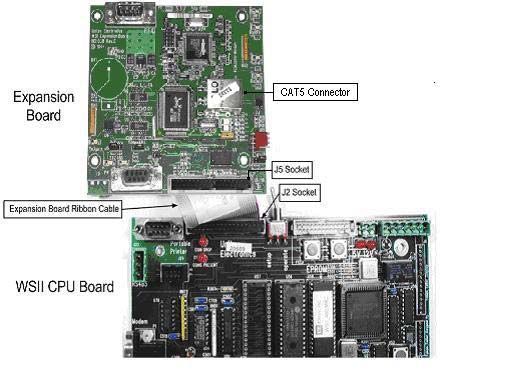
W A S H    S E L E C T   I I

           WASH SELECT II INSTALLATION MANUAL

        This manual provides comprehensive operational procedures for the Wash Select II. In this
        manual, we will discuss the setup, operation and maintenance of the Wash Select II.

        If further assistance is needed, please contact the distributor from which the product was
        purchased.

        When calling for assistance, you must have the following information available:

        Wash Select II Serial Number:

        Distributor Name:

C O P Y R I G H T

        © 2012 Unitec, Incorporated. All rights reserved. No part of this book, including text, screen
        examples, diagrams, or icons, may be reproduced or transmitted in any form, by any means
        (electronic, photocopying, recording, or otherwise) without prior written permission of Unitec,
        Incorporated.
T R A D E M A R K S

        Enterlink, Wash Select II, Wash Select II POS, WashChange, VIP Wash Pass, Customized
        VIP Wash Pass, VIP Wash Coupons, Unitec, and the Unitec Logo are trademarks, service
        marks, or registered trademarks of Unitec, Incorporated.

        Givex is the registered trademark of Givex Incorporated.

        CoinCo is the registered trademark of Coin Acceptors, Inc.

        All other products, services, and company names are trademarks or registered trademarks of
        their respective owners.

    Document Number:     WS21001
    Document Title:      Wash Select II POS Installation Manual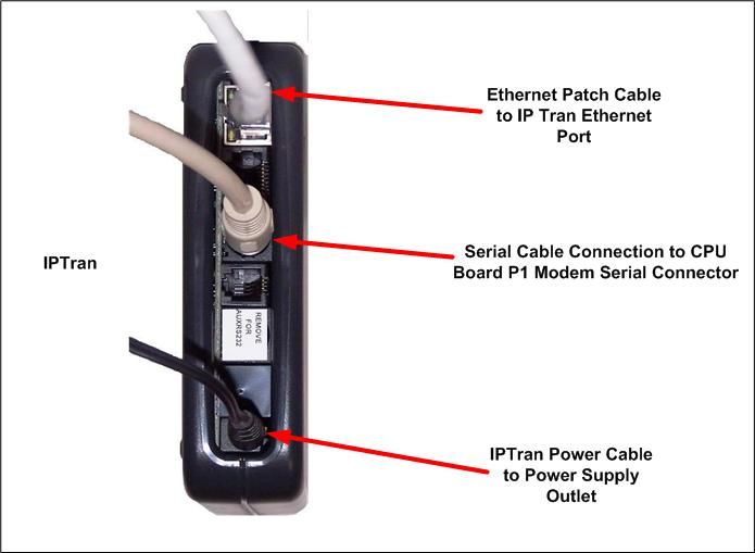
W A S H        S E L E C T           I I

Table of Contents
1   Site Planning ...................................................................................................................................1
    1.1 Electrical Planning......................................................................................................................1
          1.1.1     Site Grounding Considerations: ...................................................................................................1
          1.1.2     Electrical Requirements of the Wash Select II .............................................................................1
    1.2 Mechanical Planning ..................................................................................................................4
          1.2.1     Position of the Unit .......................................................................................................................4
          1.2.2     Mechanical Requirements............................................................................................................4
    1.3 Miscellaneous Planning .............................................................................................................5
          1.3.1     Precautionary Considerations ......................................................................................................5
          1.3.2     Unpacking & Checking Parts........................................................................................................5
          1.3.3     Wash Select II – Option Packages...............................................................................................6
2   Tools Required for Installation......................................................................................................7
    2.1 Mechanical Installation Tools.....................................................................................................7
    2.2 Electrical Installation Tools ........................................................................................................7
3   Mechanical Installation ..................................................................................................................9
    3.1 Bricking in the Wash Select II ....................................................................................................9
    3.2 Installation of the Optional Base ..............................................................................................10
          3.2.1     Preliminary Consideration ..........................................................................................................10
          3.2.2     Installation of the Wash Select II Unit.........................................................................................12
4   Electrical Installation....................................................................................................................15
    4.1 Wiring the Modem (Option) ......................................................................................................15
          4.1.1     At the Unit ..................................................................................................................................15
          4.1.2     At the Phone Jack ......................................................................................................................15
    4.2 Wiring for Internet Credit Clearance (Option) ..........................................................................16
    4.3 Wiring for WashPay Integration or Kwik Trip (Option) .............................................................16
    4.4 Wiring the Car Wash ................................................................................................................17
          4.4.1     Wash Outputs ............................................................................................................................17
          4.4.2     Wash-In-Use ..............................................................................................................................18
          4.4.3     Wash-Fault.................................................................................................................................19
    4.5 Wire the POS4000 ...................................................................................................................19
    4.6 Wiring 115 VAC Main Power ...................................................................................................19
          4.6.1     Measure Wire Lengths ...............................................................................................................20
          4.6.2     Attach the Three-prong Connector.............................................................................................20
    4.7 Wiring the Intercom ..................................................................................................................22

    Document Number:                  WS21001                                                                                                        i
    Document Title:                   Wash Select II POS Installation Manual
W A S H S E L E C T I I
4.7.1 Connecting a 2-wire Intercom System .......................................................................................23
4.7.2 Connecting a 3-wire Intercom System .......................................................................................23
4.7.3 Connecting a 4-wire Intercom System .......................................................................................24
4.8 Wiring External Fleet Device Interface.....................................................................................24
4.8.1 Hook up to Washcard Control Box .............................................................................................24
4.8.2 Hook Up to Express Key Control Box ........................................................................................25
4.8.3 Hook Up to eWash Control Box .................................................................................................26
5 Startup / Programming.................................................................................................................28
5.1 Wash Setup..............................................................................................................................28
5.1.1 Wash Prices ...............................................................................................................................28
5.1.2 Wash Names..............................................................................................................................29
5.2 Wash Interface .........................................................................................................................29
5.2.1 Relay Stacking ...........................................................................................................................29
5.2.2 Relay Latching ...........................................................................................................................29
5.2.3 Relay Pattern .............................................................................................................................30
5.2.4 Auto Out of Service Detect.........................................................................................................30
5.2.5 Wash Handshaking ....................................................................................................................31
5.2.6 Wash Fault .................................................................................................................................31
5.2.7 Out-of-Service Timer (OOS).......................................................................................................31
5.3 Customer Interface Menu.........................................................................................................31
5.3.1 Customer Stacking.....................................................................................................................31
5.3.2 Forced Selection ........................................................................................................................31
5.3.3 Allow Upgrades ..........................................................................................................................32
5.3.4 Auto Selection Time ...................................................................................................................32
5.4 Connecting to a POS4000 .......................................................................................................32
5.5 Multi-unit Fleet System (Optional Feature) ..............................................................................33
5.6 Tokens (Optional).....................................................................................................................34
5.7 Testing the Entry System .........................................................................................................35
5.8 Testing the Washes .................................................................................................................35
Appendix A. Guide for Alternate Keypad Functions....................................................................38
Appendix B. Recorded Speech Messages ....................................................................................40
Appendix C. Paging Error Codes ...................................................................................................44
Appendix D. Additional Steps for Canadian WSII Install.............................................................46
Appendix E. Single Gate Installation (Without Gate Controller).................................................54
Document Number: WS21001 ii
Document Title: Wash Select II POS Installation ManualW A S H S E L E C T I I
Index of Figures
Figure 1. Conduits with Modem Line Layout.................................................................................... 2
Figure 2. Conduits with Ethernet Cable Layout ............................................................................... 3
Figure 3. Wash Select II Base Placement ....................................................................................... 5
Figure 4. Wash Select II Installation .............................................................................................. 10
Figure 5. Straight Base .................................................................................................................. 11
Figure 6. Angled Base.................................................................................................................... 11
Figure 7. Setting Anchor Bolts ....................................................................................................... 12
Figure 8. Modem Wiring................................................................................................................. 15
Figure 9. IPTran and DataTran Connections ................................................................................. 16
Figure 10. Ethernet Cable Wiring Inside the Wash Select II.......................................................... 17
Figure 11. AC Connector ............................................................................................................... 20
Figure 12. Inside the AC Connector............................................................................................... 21
Figure 13. Thread Power Cord Through Line Insulator ................................................................. 21
Figure 14. Line - Neutral - Ground Connections ............................................................................ 22
Figure 15. Intercom Adaptor Board................................................................................................ 23
Figure 16. Standard Wash Select II Keypad.................................................................................. 28
Figure 17. Wash out of Service Sequence .................................................................................... 30
Figure 18. Alternate Keypad Functions.......................................................................................... 38
Figure 19. Outside/Inside of IDX Coin Acceptor ............................................................................ 49
Figure 20. Sample Site Layout....................................................................................................... 54
Figure 21. Gate Position ................................................................................................................ 56
Figure 22. Gate Reset Loop Dimensions....................................................................................... 56
Figure 23. Gate Base Bolt Positioning ........................................................................................... 57
Figure 24. Gate Wiring ................................................................................................................... 58
Index of Tables
Table 1. Wash Relays .................................................................................................................... 18
Table 2. Wash-In-Use Signal ......................................................................................................... 18
Table 3. Wash-fault SIGNAL.......................................................................................................... 19
Table 4. POS4000 Connection ...................................................................................................... 19
Table 5. J1 of Unitec Wash Card interface board .......................................................................... 24
Table 6. J 2 of Unitec Wash Card interface board......................................................................... 25
Table 7. Washcard input assignments........................................................................................... 25
Table 8. J1 of Unitec Wash Card interface board .......................................................................... 25
Table 9. J 2 of Unitec Wash Card interface board......................................................................... 25
Table 10. 24 VAC Source Connection ........................................................................................... 26
Table 11. J1 of Unitec Wash Card Interface Board ....................................................................... 26
Table 12. J2 of Unitec Wash Card Interface Board ....................................................................... 27
Table 13. 24 VAC Connection ....................................................................................................... 27
Table 14. POS 4000 Cable Connections ....................................................................................... 32
Table 15. Multi-Unit Fleet Cable Connections ............................................................................... 33
Table 16. Remote Wash Select II Bay Addresses ......................................................................... 34
Table 17. Pager Error Codes ......................................................................................................... 44
Table 18. Wash Select II Token Values......................................................................................... 49
Table 19. Canadian IDX Program Configuration ........................................................................... 50
Document Number: WS21001 iii
Document Title: Wash Select II POS Installation ManualW A S H S E L E C T I I
[ T H I S P A G E I N T E N T I O N A L L Y L E F T B L A N K ]
Document Number: WS21001 iv
Document Title: Wash Select II POS Installation ManualW A S H S E L E C T I I
1 Site Planning
The Wash Select II is a self-serve unattended automatic car wash entry system designed
specifically for the self-serve car wash market. The Wash Select II accepts various forms of
payment, interacts with customers at the car wash entrance, and arms the car wash.
It is important to consider a few points prior to the actual installation of the Wash Select II unit.
Among these considerations are the correct running of electrical conduit, and the proper
positioning of all of the carwash machines. In this section, these issues will be discussed in
detail. When proper planning is implemented, the Wash Select II installation will go smoothly,
and the unit will operate reliably.
1.1 Electrical Planning
1.1.1 Site Grounding Considerations:
Make sure that the protective earth ground wire does not carry any motor return current. Only
the neutral wire should carry return current.
1.1.2 Electrical Requirements of the Wash Select II
The Wash Select II will need to have 115-120 VAC on a 5-Amp dedicated breaker, which
should be provided during wash construction. Most installers will have power supplied directly
from one of the three phases used to power the wash motors and controllers. If this method is
used, special attention should be given to proper earth grounding at the unit, as well as in the
breaker panel.
Generally, most car wash manufacturers use a five-wire system to provide the arming signals
for the selected wash packages. This means that one common line and four arming input
wires are fed from the car wash’s Programmable Logic Controller (PLC) to the Wash Select II
unit. In addition to these five, a Wash-In-Use Hot and Wash-In-Use Neutral are required to
reset the wash electronics. Typically, these are also provided by the PLC. It is important to
consider this fact when planning the conduit runs, because there will need to be 2 separate
runs from the wash to the Wash Select II—one for AC power, and one for PLC Control Wires
& Optional Phone connection. If you are connecting to a POS4000 then you should have an
additional conduit run to the POS4000 (C-store), unless you have the RF option.
Another important point to remember is that the Wash Select II is equipped to accept credit
cards, so a separate run may be required from the nearest phone jack to the main conduit
run. There is no guarantee that a credit upgrade will not be performed, so the installer should
think ahead and make provisions. If there is an undedicated phone line nearby, then every
attempt should be made to try to route the conduit so that access is easily gained to it. For
example, a junction box can be placed in the run at that particular point.
If an undedicated telephone line is not nearby, try to route the conduit so that one is
accessible at a later date. An important rule to remember is that the telephone cable should
Document Number: WS21001 1
Document Title: Wash Select II POS Installation ManualW A S H S E L E C T I I
not be run in the same conduit as the main power lines. Telephone, as well as intercom
connections, can be run in the POS4000 connection conduit (Wash Select II POS system) if
you are connecting to a POS4000 in a C-store.
Figure 1. Conduits with Modem Line Layout
Document Number: WS21001 2
Document Title: Wash Select II POS Installation ManualW A S H S E L E C T I I
For Internet credit clearing, Kwik Trip, or WashPay integration, Ethernet cable will be needed.
This cable should be standard CAT 5 or CAT 6. This cable can be pulled through the existing
POS4000 communications conduit run from the C-Store to the Wash Select II. The cable
CANNOT be longer than 295 feet. The cable should extend at least 2 feet into the WSII and
be run into the back office of the store/office to the frame switch or router.
Figure 2. Conduits with Ethernet Cable Layout
DO NOT RUN CABLE OUTSIDE OF A CONDUIT!
Important:
Follow all local and National Electric Codes.
Finally, it should be understood that the Wash Select II unit is to be powered by wires of at
least 16 AWG, or larger. Failure to adhere to this recommendation could result in a fire or
injury. When installing the conduit, it is suggested that it be a minimum of ¾” in size, and be
made of metal versus PVC.
Document Number: WS21001 3
Document Title: Wash Select II POS Installation ManualW A S H S E L E C T I I
1.2 Mechanical Planning
1.2.1 Position of the Unit
The proper positioning of the Wash Select II unit is very important. Figure 2 of this section
should be used as a reference for good layout practices. There are several layout
considerations that follow, which may be a good idea to think about. They are meant for
suggestion only, and are not permission to circumvent wash manufacturer guidelines.
The Wash Select II unit should be placed 10-14 feet from the car wash entrance to ensure
the proper timing and flow of customers. The wash’s treadle switch should be centered along
the horizontal plane, approximately 18” inches out from the front of the Wash Select II unit.
Note that the Wash Select II unit extends 6” out from the leading edge of the optional straight
base and even more for an angled base (refer to angled base dimensions). This will ensure
that the car/truck’s wheel is aligned with the treadle switch, as shown in Figure 2. Finally, a
concrete post can be positioned just to the front and left corner of the unit, to act as a
protective buffer. A typical size for this post is between 30 and 35 inches.
1.2.2 Mechanical Requirements
It is strongly recommended that the unit be surrounded with a brick or concrete housing for
maximum security. However, since this may not be realistic in some installations, mounting it
on a concrete slab will suffice.
This manual assumes that the optional base will be installed simultaneously with the unit. In
this case, the concrete should be a minimum of 5” inches thick, 21” inches wide, and 13”
inches long (Refer to Figure 2). The dimensions and positioning of the mounting holes for the
base will be covered in the “Mechanical Installation” section of this manual.
The front edge of the standard base should be 18 inches from the driver’s side tire centerline.
(For angled bases, this distance should be 38.5 inches.) This provides the appropriate
distance for customers to comfortably reach the unit o make their selections.
Document Number: WS21001 4
Document Title: Wash Select II POS Installation ManualW A S H S E L E C T I I
Figure 3. Wash Select II Base Placement
1.3 Miscellaneous Planning
1.3.1 Precautionary Considerations
A large percentage of sites contain “Floor Heat”. Floor heat is an under-concrete heat
exchanger system, consisting of an elaborate network of plumbing, through which anti-freeze
circulates. In many cases this plumbing can run beside, under, or over conduit. Before
marking and drilling into any area, the site floor heat diagrams should be reviewed, and the
appropriate action taken to prevent any damage.
1.3.2 Unpacking & Checking Parts
Note: If any parts are missing, please call Unitec Technical Services at 1-443-561-1200.
Open each of the shipping boxes and ensure the following items are present:
1 . 3 . 2 . 1 Wa s h S e l e c t I I – S t a n d a r d I n s t a l l at i o n
Wash Select II Main Case Assembly
Allen Wrench For Door
Document Number: WS21001 5
Document Title: Wash Select II POS Installation ManualW A S H S E L E C T I I
Installation & Operation Manuals
Keys & Lock core set
(4) Bolts to secure top assembly to optional base
(4) Washers to be used on bolts for optional base
1.3.3 Wash Select II – Option Packages
The following items should be added to the standard installation checklist, if that specific
option was purchased with it.
W A S H S E L E C T I I – C R E D I T O P T I O N
Extra Roll of Thermal Printer Paper
IPTran credit modem
W A S H S E L E C T I I - S P E E C H O P T I O N
Microphone (for message recording)
W A S H S E L E C T I I P R O X I M I T Y S W I T C H O P T I O N
Infrared Relay Block (installed on Wash Select II power supply cover)
W A S H S E L E C T I I – O P T I O N A L B A S E
Base
(4) Concrete Anchor Bolts
(4) Washers
(4) Nuts
W A S H S E L E C T I I – W A S H P A Y I N T E G R A T I O N
CAT5E Ethernet Cable
Expansion board
Document Number: WS21001 6
Document Title: Wash Select II POS Installation ManualW A S H S E L E C T I I
2 Tools Required for Installation
2.1 Mechanical Installation Tools
It is highly recommended that the Wash Select II be bricked in! All attempts should be made
to achieve that end. It is ultimately the responsibility of individual distributors to make this
decision, and if the decision is made that it will not be possible, Unitec offers an optional base
at an affordable price. The following tools are recommended for the typical mechanical
installation of this Wash Select II unit and optional base:
6” inch or longer ratchet extension (for optional straight base)
¾” inch deep well socket and socket wrench
Open end 9/16” inch wrench
Small, thin blade, flat-tip screwdriver
Hammer drill
½” Concrete hammer drill bit
Hammer
Dual-plane Level
50’ foot tape measure
2.2 Electrical Installation Tools
In addition to the mechanical assembling of the Wash Select II unit to the base (and the entire
package to the concrete), there will be a number of electrical connections, which must be
made. These connections will require the use of the following common electrical tools:
Small, thin tipped, straight screwdriver (1/8” tip, for green Phoenix connectors)
Wire strippers (capable of handling 10-22 AWG wire)
Cable or wire tie wraps
Diagonal cutters
Needle nose pliers
Telephone wire crimping tool and 4-pin, RJ11 / 14 modular plugs (for modem, if
present) Radio Shack Part # 279-384
Document Number: WS21001 7
Document Title: Wash Select II POS Installation ManualW A S H S E L E C T I I Document Number: WS21001 8 Document Title: Wash Select II POS Installation Manual
W A S H   S E L E C T    I I

3 Mechanical Installation
                     Unitec recommends the bricking in of the WSII when installed on property that is not
                     manned or is not in plain sight of station or business personnel.
                     Unitec also recommends the connection of the WSII to a monitored security system in
         Note:       these situations or any situation where vandalism or theft may occur.
                     The use of the included door sensor and a customer supplied shock sensor mounted
                     on the door is recommended as well.

3.1 Bricking in the Wash Select II
      For optimum security the Wash Select II unit should be mounted on a concrete slab and
      bricked in.

      Tips on Bricking in:

          Conduit openings are at the right side of the bottom of the case.

          Bolt holes are at the bottom of the case to secure to the concrete slab.

          The concrete slab should be built so that the bottom of the Wash Select II™ case is
          32.5” from the floor.

      Outer dimensions of the Wash Select II are:

                       Including reinforcing             Not including reinforcing
                         band along front                band around front edge
                               edge
        Tall          23.62”                             23.24”
        Wide          18.11”                             17.74”
        Deep          19.26”                             19.25”

      The following drawing shows such an installation:

  Document Number:      WS21001                                                                9
  Document Title:       Wash Select II POS Installation Manual
W A S H S E L E C T I I
Figure 4. Wash Select II Installation
Most installers may need to increase the protection and organization of the wires that
run from the conduit to the bottom of the Wash Select II main cabinet. Flexible conduit
Hint: can be used to perform this function. The connectors can be attached to the metal
conduit by way of PVC cement.
3.2 Installation of the Optional Base
This document outlines the installation of the optional base.
3.2.1 Preliminary Consideration
The Wash Select II base comes in two distinct styles, straight and angled. The following
procedures are applicable to the straight base only. Refer to the documentation you received
with the angled base (MN1001 Angled Base Addendum) for installation procedures for the
angled base.
Document Number: WS21001 10
Document Title: Wash Select II POS Installation ManualW A S H S E L E C T I I
Figure 5. Straight Base
Figure 6. Angled Base
1. Mark the 4 holes that you intend to drill in order to mount the Wash Select II
optional base. Mark the holes with a marker as the base is sitting on top of the
concrete. It is important to keep in mind that the conduit run will need to protrude
through the large opening in the lower right corner, at least 3 inches.
DO NOT BEGIN MOUNTING OF THE BASE UNTIL ALL WIRES & CABLES HAVE
Warning: BEEN PULLED THROUGH THE CONDUIT!
Document Number: WS21001 11
Document Title: Wash Select II POS Installation ManualW A S H S E L E C T I I
2. Remove the base from the marked location and proceed to drill the holes, using
the hammer drill, and the ½” inch concrete drill bit. Ensure that the holes are
drilled deep enough to insert the anchor bolts. A good depth is approximately 2”-
2½” inches from the surface of the concrete.
3. It should be noted that while the anchor bolts are rugged and durable, they could
become damaged if struck recklessly. Care should be given to strike only the top
of the anchors, where the force will be distributed by the provided area on top of
the anchor bolt. Use the hammer to drive each of the provided anchors into the
drilled concrete holes.
Figure 7. Setting Anchor Bolts
4. When all anchor bolts have been set, place one nut onto each of them, and use
the ratchet and socket to tighten it, until as many of the threads from the bolts as
possible are showing. This first set of nuts will be used later for the correct
leveling of the base. You may remove the nuts if you have the appropriate shims
and wish to use those instead.
5. Slide the base down over top of the conduit, while feeding the wire runs up
through the conduit holes and out the top of the base. It is very important to allow
at least 66” inches of wire to remain draped over the top of the base, so that there
is enough left to make all of the electrical connections. It is also recommended
that 3” or more of conduit protrude into the base. This is to ensure that standing
water will not accumulate in the conduit. There should also be sufficient threads
on the anchor bolts left to secure the base in place with the remaining 4 nuts. If
this is not the case, the holes in the concrete were drilled too deep, and the
installer should use smaller, or no leveling nuts.
6. Place the level on top of the base, and adjust the leveling bolts with the open-
ended wrench (or add the appropriate number of shims). When it is level across
the short and long sides, hand tighten the remaining 4 nuts onto the bolts.
7. Once the base has been verified in its final position at least once, and all of the
above requirements have been met, it is safe to securely fasten the 4 nuts with
the socket wrench. When this has been successfully completed, there should be
no movement in the base whatsoever.
3.2.2 Installation of the Wash Select II Unit
1. Once the base is properly leveled and secured, ensure that there is sufficient
length of wire draped out the top to make the final electrical connections. If not,
new cable should be pulled prior to this step. If there is sufficient length, proceed
to feed them under and through the bottom of the Wash Select II main cabinet.
They should fit easily into the conduit holes, which are pre-cut into the bottom,
right-hand corner of the unit.
Document Number: WS21001 12
Document Title: Wash Select II POS Installation ManualW A S H S E L E C T I I
2. Set the unit onto the base, and align the four base holes to the pre-cut holes in
the Wash Select II. Use the remaining 4 bolts (with washers on) to secure the top
unit to the base. This is done by feeding the bolts through the holes in each of the
four corners in the bottom of the main cabinet, and then tightening with the 9/16 “
wrench.
3. If the unit is to be wired into an existing or new security alarm system, the installer
will need to acquire the 2 spade terminal connectors, termination block, sticky
wire fasteners, and appropriate lengths of 22 AWG insulated wire.
Note: The alarm device connected to the switch must be a Class-2 device.
When wiring the switch, it is important to ensure that the terminal block is mounted to an
easily accessed, un-used, portion of the Wash Select II case. It should also be in close
proximity to the naturally occurring cable runs inside of the unit. This is done in order to easily
run security system wires to one common termination point, while still keeping a relatively
neat appearance. A good recommended routing method would be to secure the wires from
the terminals of the switch along the inside, top, left side of the Wash Select II case, and have
it continue down to the bottom, just underneath the bill stacker.
The terminal block can be mounted there, and then any wires that will be brought in from the
outside system can be pulled through the same wire shielding that connects the bill validator
to the main circuit board. This same shielding can be purchased and used to wrap the switch
wires.
Document Number: WS21001 13
Document Title: Wash Select II POS Installation ManualW A S H S E L E C T I I
[ T H I S P A G E I N T E N T I O N A L L Y L E F T B L A N K ]
Document Number: WS21001 14
Document Title: Wash Select II POS Installation ManualW A S H S E L E C T I I
4 Electrical Installation
4.1 Wiring the Modem (Option)
The modem is optional. If any of the options requiring a modem are present, the
following section should be included in the electrical setup.
4.1.1 At the Unit
1. Grasp the telephone cable and measure a length sufficient to route the cable
across the back of the Wash Select II unit, and up to the backside of the modem
(inside left wall, if present). Follow the existing cable runs avoiding cables falling
behind the hopper.
2. Cut and strip back the wire, so that the telephone connector can be crimped onto
the end. Take note of which colors are going to be used, because it will need to
be duplicated on the other end of the cable.
3. Using the Crimping tool, proceed to make a solid connection between one RJ-11
connector (not included) and conductors of the modem phone cable. Any
conductors, which are unused, should be trimmed back with a pair of diagonal
cutters, so that they are even with the outer insulation.
4. Observe the correct orientation of the telephone connector (on the front end of the
modem), and carefully insert it into position.
5. Verify that the modem’s AC power plug is inserted into the upper left power outlet,
which is located at the top of the Wash Select II power supply on the back wall.
Modem
communication
cable
Phone cord
plugs in here
Power Supply
cord
Figure 8. Modem Wiring
4.1.2 At the Phone Jack
Note: The order of telephone-wire conductors must match those at the Wash Select II unit.
Document Number: WS21001 15
Document Title: Wash Select II POS Installation ManualW A S H S E L E C T I I
1. Locate the other end of the phone modem wire. This may have its own conduit
run, or it may run inside the optional POS4000 conduit or it may have a junction
box leading to the main PLC conduit. Once the end is found, strip back the
insulation, and crimp on another R-J11 modular plug. Ensure enough length
remains to install a service loop, or reach to a telephone jack.
If you do not have a dial tone present, verify all cable connections are correct and that
Note: telephone service has been turned on to the site.
2. Before inserting the plug into the wall jack, use a spare or free telephone handset
to verify that the line is active. A dial tone should be heard if service is available.
Once the service has been verified, proceed to install the plug in the jack, and
secure the cable run appropriately.
4.2 Wiring for Internet Credit Clearance (Option)
If you are using Internet credit, after the CAT5 cable is installed, the IPTran modem should be
wired as follows:
Figure 9. IPTran and DataTran Connections
4.3 Wiring for WashPay Integration or Kwik Trip (Option)
If you are integrating the WashSelect II with WashPay Site Management System or are a
Kwik Trip site, the CAT5 Ethernet cable should be terminated with an RJ45 jack and run from
Document Number: WS21001 16
Document Title: Wash Select II POS Installation ManualW A S H S E L E C T I I
the router in the C-store and plugged into the J4 Ethernet connector located on the pre-
installed expansion board, as follows:
Figure 10. Ethernet Cable Wiring Inside the Wash Select II
4.4 Wiring the Car Wash
Note: The CPU Guard may require removal prior to the wiring.
Each car wash manufacturer has its own specific color code system, and wash relay pin-
outs; therefore, it is important to review the appropriate wash documentation prior to
completing this portion of the installation.
4.4.1 Wash Outputs
1. Locate the small, thin-tipped screwdriver, and the Wash Select II main circuit
board, which is located on the inner, right-hand wall of the Wash Select II unit. On
the lower left-hand corner of the CPU, there is a green, 10-Pin phoenix connector,
which is labeled “J-17 - Car wash Relays” (in white), directly above the connector.
Note: Make note of these connections for later programming!
Document Number: WS21001 17
Document Title: Wash Select II POS Installation ManualW A S H S E L E C T I I
2. Remove this connector from the socket and hold it so that the pin marked #1 is on
the left side. Use the screwdriver to open and/or secure the manufacturer wash
wires to each of the appropriate Unitec relay locations in accordance with the
following table:
Table 1. Wash Relays
POS4000,
Wash Select II CPU
Enterlink E-system, Wash
Signal: board (lower left
Equivalent Select V1
corner) Location:
Equivalent
Wash Relay Common J-17, Pin 9 PC Conn. A pin 8
Wash Output #1 J-17, Pin 1 P1 Conn. B pin 1
Wash Output #2 J-17, Pin 2 P2 Conn. B pin 2
Wash Output #3 J-17, Pin 3 P3 Conn. B pin 3
Wash Output #4 J-17, Pin 4 P4 Conn. B pin 4
Spare Option Relays J-17, Pins 5-8 P5-8 Conn. B pin 5-8
4.4.2 Wash-In-Use
At the beginning of this manual, a reset circuit for the wash electronics was mentioned as a
requirement. This is what we often refer to as a “Wash-In-Use” signal. It is not uncommon for
values of this voltage to be as much as 115-120 VAC, so it is extremely important to verify
that there is no power applied to any of the wash components before proceeding. In previous
models offered by Unitec, there was a need to set a jumper on the CPU, in order to program
it for a 24VAC or a 120VAC circuit; however, this is not the case with the Wash Select II. This
unit is fully capable of dealing with all ranges of wash-in-use voltage.
1. Locate the Wash Select II CPU board and remove the green Phoenix connector
from the socket labeled J-18. This will be located on the lower left-hand corner of
the CPU. Use the screwdriver to open the terminals marked as pins 1& 2.
2. Identify the signals provided as a “Wash-In-Use Hot” and a “Wash-In-Use
Neutral” coming from the wash PLC. Install the two signal wires in accordance
with the following table:
Table 2. Wash-In-Use Signal
Wash Select II CPU POS4000,
Enterlink
Signal: board Location (lower E-system, Wash
Equivalent
left corner): Select V1 Equivalent
Wash-In-Use Hot J-18, Pin #1 WUH Conn. D pin 1
Wash-In-Use Neutral J-18, Pin # 2 WUN Conn. D pin 2
Document Number: WS21001 18
Document Title: Wash Select II POS Installation ManualW A S H S E L E C T I I
4.4.3 Wash-Fault
Some car wash manufactures include another interface signal to a unit, the WASH-FAULT
signal. This signal could have a voltage as high as 115VAC, and the installer is advised to
take the necessary precautions during installation.
1. Locate the same connector to which the WIU signal is connected to in section
4.1.5 above, J-18 in the lower left corner of the CPU. The Wash-Fault Hot and
Wash-Fault Neutral are connected to pins 3 and 4 respectively as shown in the
table below.
Table 3. Wash-fault SIGNAL
Wash Select II POS4000,
CPU board Enterlink E-system, Wash
Signal:
Location (lower Equivalent Select V1
left corner): Equivalent
Wash-Fault Hot J-18, Pin #3 N/A N/A
Wash-Fault Neutral J-18, Pin # 4 N/A N/A
4.5 Wire the POS4000
If you have an optional POS4000 connection (Wash Select II POS) wire the communications
cable provided with the POS4000 as follows:
Table 4. POS4000 Connection
POS4000 Wash Select II
connector J22
Pin 1 – White Pin 1 – White
Pin 2 – Red Pin 2 – Red
Pin 3 – Black Pin 3 – Black
Shield – Not Shield, strap to base
connected mounting bolt in case.
4.6 Wiring 115 VAC Main Power
There is a 3-Prong connector located in a socket on the Wash Select II main power supply
assembly (lower right-hand corner on back wall). It may be necessary to pull the coin hopper
out from its position in order to gain access to it. This is done by simply lifting up on the coin
Document Number: WS21001 19
Document Title: Wash Select II POS Installation ManualW A S H S E L E C T I I
hopper handle, and pulling it out the front. The cable that connects it to the CPU board will
need to be removed as well. Once the power connector has been located, proceed with the
rest of this section.
4.6.1 Measure Wire Lengths
1. Along with the wires that were already pulled there should be a three-conductor
cable for the main 120 VAC power. This cable should be 16 AWG or greater, and
should consist of an environmentally rated black, white, and green colored wire.
When this wire is located, use the same method employed to install the modem
to neatly route this wire back to the Wash Select II power supply.
2. Use the wire strippers to peel back about 2”-3” inches of insulation from the main
cable, and then remove approximately ¼” inch from the ends of the individual
wires.
4.6.2 Attach the Three-prong Connector
1. Locate the 3-pronged AC connector (See Figure 8). Disassemble the outer
housing by loosening the housing assembly screw, located on the top of the AC
connector.
Figure 11. AC Connector
Once opened, you will see the white plastic stabilizer plate as well as the black line insulator.
(See Figure 9)
Document Number: WS21001 20
Document Title: Wash Select II POS Installation ManualW A S H S E L E C T I I
Figure 12. Inside the AC Connector
2. Remove the line insulator and set it aside for the next step. Remove the screw
holding the stabilizer plate in place and set both aside until after you have finished
securing the wires.
3. Thread the power cord (with the 3 exposed conductors) through the hole in the
bottom of the line insulator. Continue to feed it through until about ½” of outer
insulation is protruding through the top. (See Figure 10)
Figure 13. Thread Power Cord Through Line Insulator
4. Even though the proper wire configuration is embossed in the plastic cover, it is
often very difficult to locate and verify. Refer to the drawing below for Line (HOT),
Neutral and Ground connections. Secure these power wires by unscrewing the 3
terminal screws just enough to slide the end of the wires through the provided
clamps. Re-tighten the screws to hold the wires in place.
Document Number: WS21001 21
Document Title: Wash Select II POS Installation ManualW A S H S E L E C T I I
Figure 14. Line - Neutral - Ground Connections
5. When all of the wires have been attached, pull the rubber insulation cover up to
the housing, and insert it into its original location. The three wires should be
trimmed back to a length small enough to allow for a tiny portion of the main cable
insulation to protrude into the case, without affecting the ease with which the top
and bottom pieces could be closed. Screw the stabilizer plate back into its original
position.
6. Re-assemble the AC connector and insert it into the connector located on the
lower right-hand corner of the Wash Select II power supply. Use any available
wire ties to route and secure any extra cable along the lower right inside wall
(follow the harness).
4.7 Wiring the Intercom
If your unit has the intercom option installed, ensure the Help button wiring from the speaker
to the intercom board and the power connection to the J10 connection on the CPU board are
in place.
Document Number: WS21001 22
Document Title: Wash Select II POS Installation ManualW A S H S E L E C T I I
Intercom cable
2-wire connection: pin-1 =
audio/call feed. Pin-2 =
audio/call ground
Figure 15. Intercom Adaptor Board
4.7.1 Connecting a 2-wire Intercom System
1. Locate the 2-pin connector on the “Intercom Adapter Board”. (See Figure above.)
2. Use a small flathead screwdriver to loosen the screws on the top of the 2 pin connector.
3. Locate the “Audio/Call Feed” wire of the intercom system.
4. Attach the “Audio/Call Feed” wire to pin 1 and tighten the screw to pin 1.
5. Locate the “Audio/Call Ground” wire of the intercom system.
6. Attach the “Audio/Call Ground” wire to pin 2 and then tighten the screw to pin 2.
4.7.2 Connecting a 3-wire Intercom System
1. Locate the 3-pin connector on the “Intercom Adapter Board”. (See Figure 4.)
2. Use a small flathead screwdriver to loosen the screws on the top of the 3 pin connector.
3. Locate the “Call Feed” wire of the intercom system.
4. Attach the “Call Feed” wire to pin 1 of the 3-pin connector and then tighten the screw.
5. Locate the “Audio Feed” wire of the intercom system.
6. Attach the “Audio Feed” wire to pin 2 of the 3-pin connector and then tighten the screw.
7. Locate the “Audio/Call Ground” wire of the intercom system.
8. Attach the “Audio/Call Ground” wire to pin 3 of the 3-pin connector and then tighten the
screw.
Document Number: WS21001 23
Document Title: Wash Select II POS Installation ManualW A S H S E L E C T I I
4.7.3 Connecting a 4-wire Intercom System
1. Locate the 4-pin connector on the “Intercom Adapter Board”. (See Figure 4.)
2. Use a small flathead screwdriver to loosen the screws on the top of the 4 pin connector.
3. Locate the “Call Feed” wire of the intercom system.
4. Attach the “Call Feed” wire to pin 1 of the 4-pin connector and then tighten the screw.
5. Locate the “Call Ground” wire of the intercom system.
6. Attach the “Call Ground” wire to pin 2 of the 4-pin connector and tighten the screw.
7. Locate the “Audio Feed” wire of the intercom system.
8. Attach the “Audio Feed” wire to pin 3 of the 4-pin connector and then tighten the screw.
9. Locate the “Audio Ground” wire of the intercom system.
10. Attach the “Audio Ground” wire to pin 4 of the 4-pin connector and tighten the screw.
4.8 Wiring External Fleet Device Interface
For this option to work, you need to have an EXT FLEET card plugged to J6 and J7 on the
I/O board (I/O board is located on the Wash Select II door).
Depending on the type of external fleet device you are connecting to (eWash, Wash Card or
Express Key), one of the following connections will have the Ext Fleet system up and
running.
4.8.1 Hook up to Washcard Control Box
Remove connector J1 from the Ext Fleet card on the lower left of the I/O board and make the
following connections.
J1 of Unitec Wash Card interface board
Table 5. J1 of Unitec Wash Card interface board
Pin Number Signal Name Connect to
1 Input 1 A Washcard TB-C pin 2 (C)
2 Input 1 B Pin 5 of J1 (this connector)
3 Input 2 A
4 Input 2 B
5 10-16VDC+ Isolated Pin 2 of J1 (this connector)
6 10-16VDC- Isolated Washcard TB-C pin 3 (N.O)
Remove connector J2 from the Ext Fleet card on the lower left of the I/O board and make the
following connections.
Document Number: WS21001 24
Document Title: Wash Select II POS Installation ManualW A S H S E L E C T I I
Table 6. J 2 of Unitec Wash Card interface board
Pin Number Signal Name Connect to
1 Output 1 N.O. Washcard TB-A pin 10 (Input 5)
2 Output 2 N.O. Washcard TB-A pin 12 (Input 6)
3 Output 3 N.O. Washcard TB-A pin 14 (Input 7)
4 Output 4 N.O Washcard TB-A pin 16 (Input 8)
5 Output Common Washcard TB-A pin 11 (Common 5+6)
Table 7. Washcard input assignments
Input Corresponding Wash Select II wash & display
Washcard TB-A pin 10 (Input 5) Wash 1 (Display at bottom) typically least expensive wash
Washcard TB-A pin 12 (Input 6) Wash 2 (Display 2nd from bottom)
Washcard TB-A pin 14 (Input 7) Wash 3 (Display 2nd from top)
Washcard TB-A pin 16 (Input 8) Wash 4 (Display at top) typically the most expensive wash
4.8.2 Hook Up to Express Key Control Box
Remove connector J1 from the Ext Fleet card on the lower left of the I/O board and make the
following connections.
(The Express Key control box has recently been changed. It is important that you know which
version your unit has when making the connections. The old version is a large white box. The
new version is a small green circuit board.
Table 8. J1 of Unitec Wash Card interface board
Pin Signal Name Connect to Connect to
Number (Old Version) (New Version)
1 Input 1 A Express key JP 3 Relay In (purple) Express key JP 3 Relay In
(spade plug)
2 Input 1 B Pin 5 of J1 (this connector) Pin 5 of J1 (this connector)
3 Input 2 A
4 Input 2 B
5 10-16VDC+ Isolated Pin 2 of J1 (this connector) Pin 2 of J1 (this connector)
6 10-16VDC- Isolated Express key JP 3 Relay Out Express key JP 3 Relay Out
(brown/white) (spade plug)
Remove connector J2 from the Ext Fleet card on the lower left of the I/O board and make the
following connections:
Table 9. J 2 of Unitec Wash Card interface board
Pin Signal Name Connect to Connect to:
Document Number: WS21001 25
Document Title: Wash Select II POS Installation ManualW A S H S E L E C T I I
Number (Old Version) (New Version)
1 Output 1 N.O. Express key JP5a Pin 4 (Button 4) Express key JP5a Pin 4
(Gray)
2 Output 2 N.O. Express key JP5a Pin 3 (Button 3) Express key JP5a Pin 3
(White)
3 Output 3 N.O. Express key JP5a Pin 2 (Button 2) Express key JP5a Pin 2
(Green)
4 Output 4 N.O Express key JP5a Pin 1 (Button 1) Express key JP5a Pin 1
(Orange)
5 Output Common Express key JP5a Pin 5 (Common) Express key JP5a Pin 5
(Black)
Note: Express key should be configured for a 1 second output pulse
A 24 VAC power source may be tapped from the Wash Select II power supply on the upper
right of the inside back of the unit.
Grey proximity Block on top back power supply panel. (The chart below is for the old version
Express Key control box only)
Table 10. 24 VAC Source Connection
Terminal Signal Connect to
Pin 2 24AC hot Grey
Pin 10 N24AC neutral White
4.8.3 Hook Up to eWash Control Box
Remove connector J1 from the Ext Fleet card on the lower left of the I/O board and make the
following connections.
Table 11. J1 of Unitec Wash Card Interface Board
Pin Number Signal Name Connect to
1 Input 1 A eWash J5 Pin 6
2 Input 1 B Pin 5 of J1 (this connector)
3 Input 2 A
4 Input 2 B
5 10-16VDC+ Isolated Pin 2 of J1 (this connector)
Document Number: WS21001 26
Document Title: Wash Select II POS Installation ManualW A S H S E L E C T I I
6 10-16VDC- Isolated eWash J5 Pin 5
Remove connector J2 from the Ext Fleet card on the lower left of the I/O board and make the
following connections.
Table 12. J2 of Unitec Wash Card Interface Board
Pin Number Signal Name Connect to
1 Output 1 N.O. EWash J1 Pin 16
2 Output 2 N.O. EWash J1 Pin 17
3 Output 3 N.O. EWash J1 Pin 17
4 Output 4 N.O EWash J1 Pin 18
5 Output Common EWash J1 Pin 15
A 24 VAC power source may be tapped from the grey proximity block located inside the
Wash Select II beside the power supply on the upper right of the inside back of the unit.
Table 13. 24 VAC Connection
TERMINAL SIGNAL CONNECTED TO
PIN 2 24 VAC HOT eWash J5 Pins 6 & 6 and
eWash J1 Pin 2
PIN 10 24VAC NEUTRAL eWash J5 Pin 7 and
eWash J1 Pin 1
Document Number: WS21001 27
Document Title: Wash Select II POS Installation ManualW A S H S E L E C T I I
5 Startup / Programming
For the following sections, the Wash Select II unit must be powered and placed into the
operational state known as “SETUP MODE”. The unit can be operated as such by placing
the toggle switch (located in the top and middle portion of the main circuit board) towards the
rear of the unit. The position of the switch can be verified by looking at the circuit board and
making sure that the correct position is written next to it, or by simply viewing the customer
display screen to verify that the correct status is shown.
While in setup mode, the keypad is used as a data input device. What this means is that each
key may have more than one function, in addition to the numeric place it occupies. For a
complete list of the alternate functions, refer to Appendix A. The installer needs to be aware
of the following key functions (assuming the standard Wash Select II keypad) for correct entry
of data:
Figure 16. Standard Wash Select II Keypad
If you are installing a Canadian version Wash Select II, refer to Appendix D for more
Note: information.
5.1 Wash Setup
This segment will step through the setup of the wash prices and names. Each of these
functions can be found under the “Wash Setup” category of the setup menu, which will be
presented on the main customer display. If you have a POS4000 connected to your system
then you may configure the Wash Select II first then configure the POS4000 next. You may
configure the Wash Select II names and prices at the POS4000 and the Wash Select II will
be updated if it is communicating at the time.
5.1.1 Wash Prices
In Setup mode scroll to the Wash Setup menu, then select and scroll to the wash that you
wish to change the price for and press (*) to select it. The wash prices should be input in
order, from the least expensive (wash 1/bottom display) to most expensive (wash 4/top
display). To disable a wash from the available choices, input a price of zero dollars followed
Document Number: WS21001- L 28
Document Name: Wash Select II POS Installation Manual 5.00W A S H S E L E C T I I
by the (*)-key. All wash prices must be input as cents. For example, a wash price of $4.00
would be entered as (4) (0) (0) (*).
5.1.2 Wash Names
Programming customized wash names uses alphanumeric characters. In this application, the
(#)-key doubles as a space-bar, as well as moves from one letter’s location one place to the
right into the next letter’s location. To begin the process, access the “Wash Setup” menu and
scroll using the 3 -key to select the wash name you wish to change. Refer to Appendix A of
this manual for entering text.
5.2 Wash Interface
Different wash manufactures will require a specific style of output relay pulse in order to
function properly. The “Wash Interface” part of the programming is designed to bridge the
gap of incompatibilities among many different logic controller (PLC) signals, and unit control
signals. Some carwashes require the ability to disable cash upgrades or create just a
momentary pulse, while others would require the ability to hold a wash relay closed.
5.2.1 Relay Stacking
Relay stacking is the ability for Wash Select II™ to hold back all wash arming signals while
the wash is “In Use”. Most car wash systems will work with or prefer to work with the “Relay
Stacking” set to “YES/Enabled”. Some systems which have bay entry signage built into the
carwash may require the “Relay Stacking” to be set to “No/Disabled”.
Enabled – No arming signals will be sent to the wash if the wash is “In Use” (See
Wash Handshaking). If a customer comes up to the unit and purchases a wash while
another customer is in the wash, the Wash Select II™ will wait till the wash is not “In
Use”, before sending the second customer‘s wash arming signal.
Disabled – The Wash Select II™ will send any wash arming signal immediately to the
Carwash regardless of the state of the carwash.
Default Setting is: Yes/Enabled.
5.2.2 Relay Latching
Relay Latching describes the type of relay output for the wash arming signals. Most car
washes prefer the signals to be “No/Pulsed”.
Yes/Latched – Relays are turned on when the arming signal is sent to the carwash.
The relays stay on until either a customer upgrades the wash (if upgrading is
enabled) or the wash becomes “In Use”.
Document Number: WS21001 29
Document Title: Wash Select II POS Installation ManualYou can also read