ADDERLINK INFINITY USER GUIDE - ALIF1000 ALIF2000 ALIF2002

Page created by Crystal Graham
 
CONTINUE READING
ADDERLINK INFINITY USER GUIDE - ALIF1000 ALIF2000 ALIF2002
{
                         ALIF1000
AdderLink Infinity       ALIF2000
User Guide               ALIF2002

                         
Contents
Introduction                                                                                       Configuration

                                                                                                                                                                                                       
 AdderLink ALIF1000T and ALIF1000R unit features...................3                                Initial configuration...................................................................19
 AdderLink ALIF2000T and ALIF2000R unit features...................4                                   Manual factory reset.............................................................19
 What’s in the box (ALIF1000).......................................................5                  AdderLink Infinity browser-based configuration utility.....20
 What’s in the box (ALIF2000).......................................................6               Performing an upgrade.............................................................21
 What you may additionally need................................................7

                                                                                                                                                                                                       
                                                                                                   Operation
Installation                                                                                        Front panel indicators................................................................22
 Mounting......................................................................................8
 Connections..................................................................................9    Further information
   TX video link..........................................................................10        Getting assistance.......................................................................23
   TX audio links.........................................................................11        Appendix A.................................................................................24

                                                                                                                                                                                                       
   TX USB link.............................................................................12         Tips for success when networking ALIF units ......................24
   TX AUX port...........................................................................12         Appendix B.................................................................................26
   TX power in............................................................................13          Troubleshooting....................................................................26
     Power adapter identification...........................................13                      Appendix C.................................................................................28
   TX/RX network link................................................................14

                                                                                                                                                                                                     
                                                                                                      Glossary..................................................................................28

                                                                                                                                                                                                       
   RX video display.....................................................................15          Appendix D.................................................................................31
   RX microphone & speakers...................................................16                         RS232 ‘null-modem’ cable pin-out...................................31
   RX USB devices.......................................................................17               Supported video modes....................................................31
   RX AUX port...........................................................................17              ALIF 1000 and ALIF 2000 general specifications..............31
   RX power in............................................................................18        Appendix E..................................................................................32
     Power adapter identification...........................................18                        Fibre modules and cables (ALIF 2000 units only) ................32

                                                                                                                                                                                                       
                                                                                                    Appendix F..................................................................................33
                                                                                                      Additional features available on ALIF2002T........................33
                                                                                                    Warranty and Safety information.............................................34
                                                                                                    Radio Frequency Energy............................................................35

                                                                                                   Index                                                                                                 1
Introduction
 Thank you for choosing AdderLink Infinity, otherwise             One-to-one configuration
                                                                  The simplest configuration links one RX unit to a single TX unit, either by a direct
 known as ALIF. ALIF represents a major advance in the
                                                                  link or over much greater distances via a Gigabit (or Fibre) Ethernet network.
 capabilities of digital extenders and switches. By encoding

                                                                                                                                                                                                                                     
 high quality DVI video, digital audio and USB connections
 into Internet Protocol (IP) messages, ALIF offers highly
                                                                                 ALIF TX                                                                           ALIF RX
 advanced and flexible signal switching capabilities.
 Adder’s extensive knowledge of interfacing techniques
 and high speed networking has allowed us to develop
 new ways to break the chains of local DVI, USB and audio

                                                                                                                                                                                                                                     
 connections. With ALIF, distance is finally no barrier to high
 specification, high performance computing. Furthermore,          One-to-many configuration
 since all signals are now IP, the most elaborate and yet         Using multicast techniques, an unlimited number of receivers*                                    ALIF RX
 simple-to-use switching and multicast techniques make            can receive video and audio data streams from a single TX unit.
 possible a great variety of uses.
 There are two main models within the ALIF family:
                                                                                                                     Gigabit
                                                                                 ALIF TX                                                                           ALIF RX
   • ALIF1000 supports one single link DVI video stream,                                                            Ethernet

                                                                                                                                                                                                                                     
      plus microphone, speakers and up to four USB
      peripherals. ALIF1000 units are linked using Gigabit
      Ethernet.                                                         * A maximum of eleven concurrent USB inputs (via
                                                                        multiple RX units) are permitted to a single TX unit.                                      ALIF RX
   • ALIF2000 supports either two single link DVI video
      streams or one dual link (very high resolution) DVI video
      stream. This is in addition to microphone, speakers
      and up to four USB peripherals. ALIF2000 units can be

                                                                                                                                                                                                                                   
      linked using Gigabit Ethernet or Fibre Optic Links.         Mixing ALIF1000 and ALIF2000 units

                                                                                                                                                                                                                                     
                                                                  It is possible to mix ALIF1000 and ALIF2000 transmitters and receivers on a network, with the
 In both model types, there is a TX transmitter and an RX
                                                                  proviso that ALIF1000 units do not support dual link DVI video signals or fibre optic links.
 receiver. The former attaches to a single computer; the
 latter to your DVI video monitor, microphone, speakers and
 up to four USB peripherals. The distance between them is         ALIF and AIM
 limited only by the size of your network.                        Where multiple ALIF units are used on a network, we have developed the AdderLink
 In addition to separating one computer and its peripherals,      Infinity Management (AIM) server to allow comprehensive and secure central control of all
 ALIF promotes sharing. You can arrange for a limitless

                                                                                                                                                                                                                                     
                                                                  transmitters, receivers and users.
 number of screens and speakers, distributed anywhere             When using an AIM server to configure ALIF units, it
 across the network, to receive video and audio. You can          is vital that all ALIF units that you wish to locate and                     AdderLink

 also switch between any number of transmitter units from
                                                                                                                                                                             ADM   USR   UNC   ETH1   ETH2   PWR

                                                                  control are set to their factory default settings. Otherwise
 a single screen, keyboard and mouse in order to monitor a        they will not be located by the AIM server. If necessary,                    MANAGEMENT SERVER
                                                                                                                                                                             ADM   USR   UNC   ETH1   ETH2   PWR

 potentially vast collection of remote systems.
                                                                                                                                                                                                                   www.adder.com

                                                                  perform a factory reset on each ALIF unit.
 All units feature browser-based configuration utilities to       Please also see Appendix A - Tips for success when networking ALIF units
 allow quick and easy set up, from near or far.
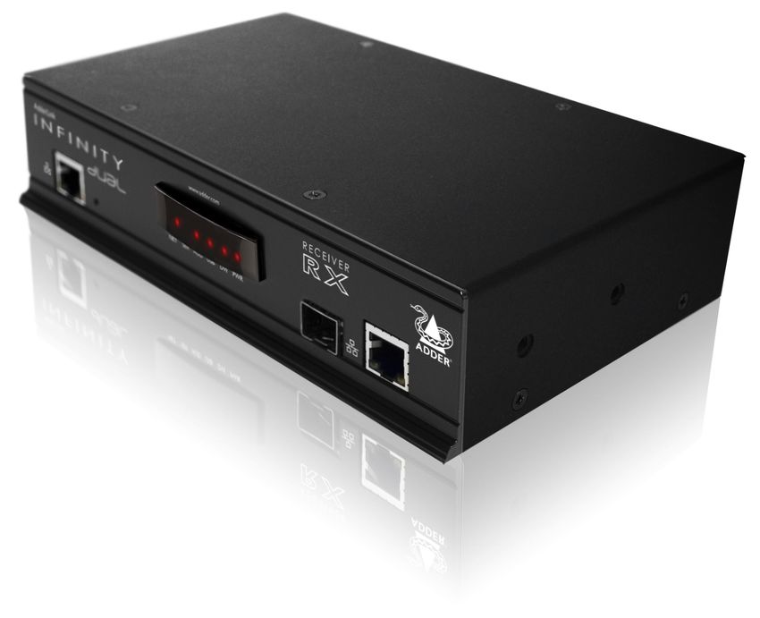
                                                                                                                                                                                                                                       2
AdderLink ALIF1000T and ALIF1000R unit features
   The ALIF1000 units are housed within durable, metallic enclosures with most connectors situated at the rear panel -
   the Ethernet ports are situated on the front panels. The smart front faces also feature the operation indicators.

ALIF1000T (transmitter) - front                                                                                   ALIF1000R (receiver) - front

                                                                                                                                                                                                                                   
                                                                                     TRANSMIT                                                                                                       RECEIVER
      AdderLink                                                                                                         AdderLink

                                                                                                  www.adder.com                                                                                                  www.adder.com

                                             NET SER AUD USB DVI PWR                                                                                       NET SER AUD USB DVI PWR

                                                                                                                                                                                                                                   
                               Indicators                                             Gigabit                                                    Indicators                                          Gigabit
    These six indicators clearly show the key aspects of operation:                  Ethernet                         These six indicators clearly show the key aspects of operation:               Ethernet
    • NET On when valid network link is present.                                       port                           • NET On when valid network link is present.                                    port
          Flashes when the unit is in error.                                                                                Flashes when the unit is in error.
    • SER On when the AUX (serial) port is enabled and active.                                                        • SER On when the AUX (serial) port is enabled and active.
    • AUD On when audio is enabled and active.                                                                        • AUD On when audio is enabled and active.

                                                                                                                                                                                                                                   
    • USB On when USB is enabled and active.                                                                          • USB On when USB is enabled and active.
    • DVI On when DVI video is enabled.                                                                               • DVI On when DVI video is enabled.
    • PWR Power indicator.                                                                                            • PWR Power indicator.

ALIF1000T (transmitter) - rear                                                                                    ALIF1000R (receiver) - rear

                                                                                                                                                                                                                                 
                                                                                                                                                                                                                                   
        INDOOR                                                                                                           INDOOR                                                      LINE IN/
       USE ONLY OPTIONS              DVI-D                      LINE OUT   LINE IN          AUX                         USE ONLY     OPTIONS     DVI-D                                        LINE OUT     AUX
                                                                                                                                                                                      MIC IN

                    1 2                                                                                                                1 2
                   ON                                                                                                                 ON

                   1 2                                                                                                                1 2
       5V   2.5A                                         COMPUTER                                                       5V    2.5A                                  USER CONSOLE

                                                                                                                                                                                                                                   
      Power               USB        Video                             Audio               AUX                          Power                   Video                 USB               Audio             AUX
      input               port       input                              line              (serial)                      input                   output                ports              line            (serial)
                                                                       in/out               port                                                                                        in/out             port
       Configuration                                                                                                         Configuration
         switches                                                                                                              switches

                                                                                                                                                                                                                                     3
AdderLink ALIF2000T and ALIF2000R unit features
   The ALIF2000 units are housed within durable, metallic enclosures with most connectors situated at the rear panel - the
   Ethernet and fibre ports are situated on the front panels. The smart front faces also feature the operation indicators.

ALIF2000T (transmitter) - front                                                                                                    ALIF2000R (receiver) - front

                                                                                                                                                                                                                                                      
     AdderLink                                            www.adder.com                    TRANSMIT                                     AdderLink                                  www.adder.com                   RECEIVER

                                                                                                                                                                                                                                                      
                                                    NET SER AUD USB   DVI PWR                                                                                                NET SER AUD USB   DVI PWR

             Reserved                                                                       Fibre       Gigabit                               Reserved                                                              Fibre      Gigabit
                                                                                           module      Ethernet                                                                                                    module     Ethernet
                                                                                             slot        port                                                                                                        slot       port
                                                        Indicators                                                                                                              Indicators
                             These six indicators clearly show the key aspects of operation:                                                         These six indicators clearly show the key aspects of operation:
                       • NET On when valid network link is present.                                                                                 • NET On when valid network link is present.
                             Flashes when the unit is in error.                                                                                           Flashes when the unit is in error.

                                                                                                                                                                                                                                                      
                       • SER On when the AUX (serial) port is enabled and active.                                                                   • SER On when the AUX (serial) port is enabled and active.
                       • AUD On when audio is enabled and active.                                                                                   • AUD On when audio is enabled and active.
                       • USB On when USB is enabled and active.                                                                                     • USB On when USB is enabled and active.
                       • DVI On when either or both DVI Video channels are enabled.                                                                 • DVI On when either or both DVI Video channels are enabled.
                       • PWR Power indicator.                                                                                                       • PWR Power indicator.

                                                                                                                                                                                                                                                    
                                                                                                                                                                                                                                                      
ALIF2000T (transmitter) - rear                                                                                                     ALIF2000R (receiver) - rear

         INDOOR
        USE ONLY     OPTIONS                         DVI-D-1                     DVI-D-2                                                                                     DVI-D-2                     DVI-D-1
                                                                                                            AUX

                                                                                                                                                                                                                                                      
                       1 2
                      ON

                                                                                                      IN          OUT
                      1 2
        5V    2.5A                                                    COMPUTER                                                           5V   4A

       Power                        USB              Primary                    Secondary                  Audio         AUX            Power              USB             Secondary                     Primary              Audio       AUX
       input                        port              video                       video                     line        (serial)        input              ports             video                        video                line      (serial)
                                                      input                       input                    in/out         port                                              output                       output               in/out       port
         Configuration                                                                                                                    Configuration
           switches                                                                                                                         switches
                                                                                                                                                                                                                                                        4
What’s in the box (ALIF1000)

  ALIF1000T package
                                                                                                                                         Power adapter
                                                                                                                                         (12.5W) and

                                                                                                                                                                                                                   
                                                                                                                                         country-specific
                                                                                                                                         power lead

   Ad
     der
           Lin
               k

                                                                                                                  CD-ROM
                    NET
                          SE
                            R AU
                                D
                                    USB
                                          DV
                                            I PW
                                                R   TR
                                                         AN
                                                              SM
                                                                   IT

                                                                                                                                                                                                                   
                                                                                                                                                                                        Combined DVI-D and USB
   ALIF1000T unit                                                       ww
                                                                          w.ad
                                                                              de
                                                                                r.com                                                                                                   cable (1.8m)

                                                                                                               Four self-adhesive
                                                                                                                  rubber feet

                                                                                                                                                                                                                   
                                                                                           ALIF1000
                                                                                           Quick Start Guide
                                                                                                                                                       2 x Audio cable 2m          Serial null modem cable 2m
                                                                                                                                                      (3.5mm stereo jacks)

                                                                                                                                                                                                                 
  ALIF1000R package

                                                                                                                                                                                                                   
                                                                                                                                                  Power adapter
                                                                                                                                                  (12.5W) and
                                                                                                                                                  country-specific
                                                                                                                                                  power lead
   Ad
     der
         Lin
             k

                                                                                                                                                                             ALIF1000
                                                                                                                                                                             Quick Start Guide
                                                                                                                        CD-ROM

                                                                                                                                                                                                                   
                    NET
                          SE
                            R AU
                                D
                                    USB
                                          DV
                                            I PW
                                                R   RE
                                                         CE
                                                              IV
                                                                   ER

   ALIF1000R unit
                                                                         ww
                                                                           w.ad
                                                                               de
                                                                                   r.com

                                                                                                                    Four self-adhesive
                                                                                                                       rubber feet

                                                                                                                                                                                                                     5
What’s in the box (ALIF2000)

  ALIF2000T package
                                                                                                                                                 Power adapter
                                                                                                                                                 (20W) and
                                                                                                                                                 country-specific

                                                                                                                                                                                                                                                        
                                                                                                                                                 power lead

   Ad
     der
           Lin
               k

                                                                                                                  CD-ROM
                    NET
                          SE
                            R AU
                                D
                                    USB
                                          DV

                                                                                                                                                                                                                 Combined dual link DVI-D
                                            I PW
                                                R   TR
                                                         AN
                                                              SM
                                                                   IT

                                                                                                                                                                                                                                                        
                                                                                                                                                                                                                 and USB cable (1.8m)
                                                                        ww
                                                                          w.ad
                                                                              de
                                                                                r.com

   ALIF2000T unit

                                                                                                               Four self-adhesive
                                                                                                                  rubber feet

                                                                                                                                                                                                                                                        
                                                                                           ALIF2000
                                                                                           Quick Start Guide

                                                                                                                           Single link DVI-D to DVI-D video cable              2 x Audio cable 2m                        Serial null modem cable 2m
                                                                                                                                                                              (3.5mm stereo jacks)

                                                                                                                                                                                                                                                      
  ALIF2000R package

                                                                                                                                                                                                                                                        
                                                                                                                                                           Power adapter
                                                                                                                                                           (20W) and
                                                                                                                                                           country-specific
                                                                                                                                                           power lead
   Ad
     der
         Lin
             k

                                                                                                                                                                                                     ALIF2000
                                                                                                                                                                                                     Quick Start Guide
                                                                                                                        CD-ROM

                                                                                                                                                                                                                                                        
                    NET
                          SE
                            R AU
                                D
                                    USB
                                          DV
                                            I PW
                                                R   RE
                                                         CE
                                                              IV
                                                                   ER

                                                                         ww
                                                                           w.ad
                                                                               de
                                                                                   r.com

   ALIF2000R unit

                                                                                                                    Four self-adhesive
                                                                                                                       rubber feet

                                                                                                                                                                                                                                                          6
What you may additionally need

                                                                                                                                                                                                         
                                                           Single mode fibre module
                                                           (for ALIF2000)
                                                           Part number: SFP-SM-LC

                                                     Please refer to the table in Appendix E for
                                                    information about fibre modules and cables.
      Two 19” rack-mount brackets and four screws
      Part numbers:
      One unit per 1U rack slot: RMK4S                                                                                                                        Single link DVI-D to DVI-D video cable
      Two units per 1U rack slot: RMK4D                                                                                                                       Part number: VSCD1

                                                                                                                                                                                                         
                                                                                                   Combined dual link DVI-D and USB (USB type A to B) cable
                                                           Multi mode fibre module                 Part numbers: VSCD3 (1.8m length)
                                                           (for ALIF2000)                                        VSCD4 (5m length)
                                                           Part number: SFP-MM-LC

                                                                                                                                                                                                         
       Power adapter (12.5W) and
       country-specific power lead
       for ALIF1000 units
       Part number: PSU-IEC-5VDC-2.5A

                                                                                                                                                                  Audio cable 2m
                                                                                                                                                                  (3.5mm stereo jacks)
                                                                                                        USB cable 2m (type A to B)                                Part number: VSC22
                                                                                                        Part number: VSC24

                                                                                                                                                                                                       
                                                                                                                                                                                                         
        Power adapter (20W) and
        country-specific power lead
        for ALIF2000 units
        Part number: PSU-IEC-5VDC-4AMP
                                                                                                              Serial null modem cable 2m

                                                                                                                                                                                                         
                                                                                                              Part number: CAB-9F/9F-NULL-MODEM

                                                                                                                                                                                                           7
Installation
Mounting
   There are two main mounting methods for transmitter and receiver units:

                                                                                                                                                                                                                 
    • The supplied four self-adhesive rubber feet
    • Optional rack brackets

Connections

                                                                                                                                                     Rack brackets

                                                                                                                                                                                                                 
                                                                                                                                                         The optional brackets (plus four screws), allow the
                                                                                                                                                         units to be secured within a standard rack slot.
          Note: The ALIF units and their power
          supplies generate heat when in operation
          and will become warm to the touch.
          Do not enclose them or place them in
          locations where air cannot circulate to
          cool the equipment. Do not operate
          the equipment in ambient temperatures

                                                                                                                                                                                                                 
          exceeding 40oC. Do not place the
          products in contact with equipment
          whose surface temperature exceeds 40oC.
                                                                         IN
                                                                        US DOO
                                                                           EO R
                                                                             NL
                                                                               Y
                                                                                   OP
                                                                                        TIO
                                                                                           NS

                                                                                                                                                                                                               
                                                                                                      LIN

                                                                                                                                                                                                                 
                                                                                                          E
                                                                                                       MI IN/
                                                                                    1
                                                                                          2
                                                                        5V                               CI
                                                                                                            N LI
                                                                             2.5                                 NDEV
                                                                              SAE 1 2                                 IO
                                                                                                                       -DU
                                                                                                                           T
                                                                                 RC
                                                                                     ON
                                                                                                SO                             AU
                                                                                                     LE                           X

                                                                                                                                                      LIN
                                                                                                                                                          E
                                                                                                                                                       MI IN/
                                                                                                                                                         CI
                                                                                                                                                            N LI
                                                                                                                                                                 N
                                                                                                                                      US                          EO

                                                                                                                                                                                                                 
                                                                                                                                           ER
                                                                                                                                                CO

                                                                                                                                                                                                                   8
Connections
  Installation involves linking the ALIF TX unit to various ports on the host
  computer, while the ALIF RX unit is attached to your peripherals:

                                               VIDEO                                                                     VIDEO

                                                                                                                                                               
                                                LINK                                                                      LINK
                                              page 10                                                                   page 15
                           AUDIO                                                                                                             MIC &
                           LINKS                                                                                                           SPEAKERS
                          page 11                                                                                                           page 16
                                                                                 CABLE LINK
                                                                                  page 14

                                                                                                                                                               
                         USB                                                                                                                     USB
                        LINK                       ALIF TX                            OR                      ALIF RX                          DEVICES
                       page 12                                                                                                                 page 17
                                                                                  FIBRE LINK
                                                                                (ALIF2000 only)
                                                                                   page 14
                            SERIAL                                                                                                          SERIAL
                             LINK                                                                                                            LINK
                           page 12                                                                                                         page 17
                                              POWER                                                                     POWER

                                                                                                                                                               
                                                IN                                                                        IN
                                              page 13                                                                   page 18

                                                                                                                         Click a connection to see details

                                                                                                                                                             
                                                                                                                                                               
                                              IMPORTANT: When using an AdderLink Infinity Management box to configure
                                              ALIF units, it is vital that all ALIF units that you wish to locate and control are
                                              set to their factory default settings. Otherwise they will not be located by the
                                              AIM server. If necessary, perform a factory reset on each ALIF unit.

                                                                                                                                                               
                                              Please also see Appendix A - Tips for success when networking ALIF units

                                                                                                                                                                 9
TX video link                                             VIDEO
                                                           LINK
  ALIF units support DVI digital video       AUDIO                                    [ALIF2000 when using two single link
                                              LINKS
  signals and so use DVI-D video                                                      DVI-D displays] Connect an additional
  connectors throughout.                                                              video input from the secondary video
                                            USB                          LINK
                                                          ALIF TX                     port of the computer system using
    • ALIF1000 models can support           LINK

      a single high resolution DVI-D                                                  the supplied secondary DVI-D link
                                                                                                                                  DV
                                              SERIAL              ALIF RX             cable.

                                                                                                                                                                                
                                                                                                                                     I-
      video display at pixel clocks up         LINK
                                                                                                                                       D-1

      to 165MHz (equating to an                       POWER
                                                        IN
      example display mode of 1920 x                                                                                                                            DV
                                                                                                                                                                   I-
      1200 at 60Hz refresh).                                                                                                                                         D-2

    • ALIF2000 models can simultaneously support up to two Single Link high                                                                     CO
                                                                                                                                                     MP
      resolution video displays at pixel clocks up to 165MHz; or can alternatively                                                                        UT
                                                                                                                                                               ER
      support a single Dual Link very high Resolution video display at pixel clocks

                                                                                                                                                                                
      up to 330MHz (equating to an example display mode of 2560 x 1600 at 60
      Hz refresh).

  To make a video link                                                                 To primary video output port
   1 Wherever possible, ensure that power is disconnected from the ALIF and the
     host computer.
   2 Connect a digital video link cable to the DVI-D socket (ALIF1000) or DVI-D-1                To secondary video output port
     (ALIF2000) on the TX unit rear panel:

                                                                                                                                                                                
                                                    [ALIF1000]                        [ALIF2000 when using one very high
                                                                                      resolution DVI-D dual link display]
                                                                                      Use a DVI-D Dual Link cable (such as
                                                                                      Adder part: VSCD3) to connect the
                                           DV
                                              I-                                      primary video port of the computer

                                                                                                                                                                              
                                                D
                                                                                                                                  DV
                                                                                      system to the DVI-D-1 connector of

                                                                                                                                                                                
                                                                                                                                     I-   D-1
                                                                                      the ALIF2000. A dual link cable must
    DVI-D link from                                                                   also be used at the RX unit.
    host computer                                                                                                                                               DV
                                                                                                                                                                   I-   D-2

                                                          CO
                                                               MP                                                                               CO
                                                                                                                                                     MP
                                                                                                                                                          UT
                                                                                                                                                               ER

                                                                                                                                                                                
   3 Connect the plug at the other end of the cable to the corresponding DVI-D        VSCD3 cable to primary video output port
     video output socket of the host computer.

                                                                                                                                                                               10
TX audio links                                                     VIDEO
                                                                    LINK
  The ALIF units support two way                  AUDIO
                                                  LINKS
  stereo digital sound so that you can
  use a remote microphone as well as
                                                 USB                                LINK
  speakers.                                                          ALIF TX
                                                 LINK

  To make audio links

                                                                                                                                                                          
                                                  SERIAL                       ALIF RX
   1 Connect an audio link cable                   LINK
                                                                 POWER
     between the LINE OUT socket on                                IN
     the TX unit rear panel and the
     speaker output socket of the host
     computer.                                                                             [ALIF2000]
                                                                                           1 Connect an audio link cable
                                                 [ALIF1000]

                                                                                                                                                                          
                                                                                             between the IN     socket on           DV
                                                                                                                                       I-D-1
                                                                                             the TX unit rear panel and the
                                                                                             speaker output socket of the
                                                                                             host computer.
                                         LIN
                                             EO                                                                                                            AU
                                               UT                                                                                                            X
                                                           LIN
                                                              EI
                                                                 N                                                                                    IN
                                  CO                                                                            Speaker link from
                                       MP

                                                                                                                                                                          
      Speaker link from                     UT                                                                  host computer                                     OU
                                                 ER                                                                                                                 T
      host computer

                                                                                                                                               Microphone link
                                                                                                                                               to host computer
                                Microphone link
                                to host computer                                           2 [Where a microphone is

                                                                                                                                                                        
                                                                                                                                                                          
                                                                                             to be used]: Connect a
                                                                                             second audio link cable
   2 [Where a microphone is to be used]: Connect a second audio link cable
                                                                                             between the OUT socket
     between the LINE IN socket on the TX unit rear panel and the Line In socket
                                                                                             on the TX unit rear panel
     of the host computer.
                                                                                             and the Line In socket of
                                                                                             the host computer.

                                                                                                                                                                          
                                                                                                                                                                         11
TX USB link                                               VIDEO                   TX AUX port                                        VIDEO
                                                                                                                                      LINK
                                                           LINK
  ALIF units act as USB 2.0 hubs                AUDIO                               The AUX port is an RS232 serial        AUDIO
                                                LINKS                                                                      LINKS
  and so can provide four sockets                                                   port that allows extension of RS232
  at the RX unit with only a single                                                 signals up to a baud rate of 115200.   USB
                                                USB                                                                                                     LINK
  connection at the TX unit.                                ALIF TX        LINK     The port has software flow control,                ALIF TX
                                                LINK                                                                       LINK
                                                                                    but no hardware flow control.
  To make a USB link                                                  ALIF RX                                                                      ALIF RX

                                                                                                                                                                     
                                                 SERIAL                                                                     SERIAL
   1 Connect the type B connector                 LINK                                                                       LINK
                                                          POWER                                                                      POWER
     of the supplied USB cable to the                       IN                                                                         IN
     USB port on the TX unit rear
     panel.                                                                         To connect the AUX port
                                                                                     1 Ensure that power is removed from the ALIF unit.
                                                                                     2 Connect a suitable serial ‘null-modem’ cable (see Appendix D for pin-out)

                                                                                                                                                                     
                                                                                        between a vacant serial port on your computer and the AUX port on the
                                      OP
                                        TIO
                                                                                        right hand side of the ALIF rear panel.
                                           NS

                                       1
                                           2

                                       1
                                           2

                                                                                                                                                                     
      USB link from                                                                                                                          AU
      host computer                                                                                                                            X

                                                                                        Serial (null-modem) link
                                                                                        from your computer

                                                                                                                                                                   
   2 Connect the type A connector of the cable to a vacant USB socket on the

                                                                                                                                                                     
     host computer.

                                                                                                                                                                     
                                                                                                                                                                    12
TX power in                                       VIDEO
                                                   LINK
  Each ALIF unit is supplied with an     AUDIO
                                         LINKS
  appropriate power adapter. When
  all other connections have been
  made, connect and switch on the
                                        USB
                                        LINK
                                                       ALIF TX               LINK        Power adapter identification
  power adapter unit.                                                                    Due to the increased power requirements of the ALIF2000 series, these models
                                                                      ALIF RX            are supplied with larger capacity (20W) power adapters. The standard 12.5W

                                                                                                                                                                                
  Note: Please see Power adapter         SERIAL

  identification shown opposite.
                                          LINK
                                                  POWER
                                                                                         and higher power 20W adapters use identical housings, so within installations
                                                    IN                                   where both types are used, you need to double check the underside labels to
  To apply power in                                                                      differentiate the two types:
   1 Attach the output lead from the power adapter to the 5V socket on the rear
     panel of the unit.                                                                        12.5W model                                        20W model
                                                                                               (for ALIF1000)                                     (for ALIF2000)

                                                                                                                                                                                
                                                                                               Model: SA06-xxxxx-V                                Model: SA06-xxxxx-V
                                                                                               Input: 100-240V                                    Input: 100-240V
                                                                                               Output: 5V 2.5A (12.5W Max.)                       Output: 5V 4A (20W Max.)
                                                   IN
                                                  US DOO
                                                     EO R
                                                       NL
                                                         Y
                                                              OP
                                                                T

                                                               1
                                                                    Note: Ensure that
                                                                    Option switches                                        xxx
                                                                                                                        6-x V
                                                                                                                               x-V
                                                                                                                                   (12
                                                                                                                                      .5W
                                                                                                                                          Ma
                                                                                                                                            x.)

                                                  5V                                                               SA0 -240 2.5A
                                                                    1 and 2 are both                           del: t: 100 5V

                                                                                                                                                                                
                                                                                                             o
                                                       2.5                                                  M pu ut:
                                                          A    1                                               In utp
                                                                                                                   O
                                                                    in the ‘off’ (up)
      Power lead from                                               position to enable
      power adapter                                                 normal operation
                                                                    of the unit.                                                                              Power adapter

                                                                                                                                                                              
                                                                                                                                                                                
   2 Connect the IEC connector of the supplied country-specific power lead to
                                                                                         No damage will be caused if the 12.5W adapter and the 20W adapter are used
     the socket of the power adapter.
                                                                                         in place of each other on either of the ALIF1000 or ALIF2000 units. However,
   3 Connect the power lead to a nearby main supply socket.                              correct operation of ALIF2000 units can only be guaranteed if a 20W power
  Note: Both the unit and its power supply generate heat when in operation and           adapter is used. Always ensure that only ADDER 5-volt power supplies are used
  will become warm to the touch. Do not enclose them or place them in locations          to power the units.
  where air cannot circulate to cool the equipment. Do not operate the equipment

                                                                                                                                                                                
  in ambient temperatures exceeding 40oC. Do not place the products in contact
  with equipment whose surface temperature exceeds 40oC.

                                                                                                                                                                               13
TX/RX network link                                                                                        VIDEO                                VIDEO
                                                                                                           LINK                               DISPLAY
  ALIF units can be either connected directly to each other or via a Gigabit Ethernet           AUDIO                                                     MIC &
                                                                                                LINKS                                                   SPEAKERS
  network. Additionally, ALIF2000 units can be networked by fibre optic links.
  For direct links over Ethernet cable, the length of cable should not exceed 100              USB                           LINK
                                                                                                                              LINK                          USB
                                                                                                             ALIF TX                      ALIF RX
  metres (328 feet). Network cables used for connections may be category 5, 5e, 6 or           LINK                                                       DEVICES
  7 twisted-pair cable. ALIF TX units have an autosensing capability on their network

                                                                                                                                                                                  
                                                                                                SERIAL                                                  SERIAL
  interfaces, so for direct point-to-point connections, no ‘crossover’ Ethernet cable is         LINK                                                    LINK
  required.                                                                                               POWER                                POWER
                                                                                                            IN                                   IN
  For direct links over fibre optic links, varying distances can be achieved depending
  on the module and cable types used. Please refer to the table in Appendix E for
  detailed information. The fibre cable(s) must be crossover cable(s).                       Please see Appendix A for important tips about networking ALIF units.

  To link ALIF units using Gigabit Ethernet

                                                                                                                                                                                  
   1 Connect a CAT 5, 5e, 6, or 7 cable to the socket on the front panel of the ALIF
      unit.                                                                                  To link ALIF units using fibre optic links (ALIF2000 only)
                                                                                              1 Insert the optional fibre module (SFP-MM-LC or SFP-SM-LC) into the
                                                                                                 aperture on the ALIF2000 front panel:

     CAT 5, 5e, 6, or 7 link either
     directly from the other ALIF

                                                                                                                                                                                  
     unit or from a Gigabit Ethernet                                                             Optional fibre module
     switch
                                                                            ww
                                                                              w.a
                                                                                  dder
                                                                                      .co
                                                                                         m

                                                                                                                                                                                
                                                                                                                                                                                  
                                                                                              2 Connect the transmit and receive fibre links to the fibre module and close
   2 Connect the other end of the cable either to the other ALIF unit or to a                   the latch over the link connectors to lock them into place.
     Gigabit Ethernet switch, as appropriate.
   3 [For connections via a network] repeat steps 1 and 2 for the other ALIF unit.

     [ALIF2000] When making Gigabit Ethernet links
                                                                                                  Transmit and receive

                                                                                                                                                                                  
                       AdderLink             www.adder.com
                                                                                                  fibre links

                                       NET SER AUD USB   DVI PWR

                      Reserved for                           Use only the right hand port
                       future use                             for Gigabit Ethernet links      3 Connect the other end of the fibre links either to the other AdderLink
                                                                                                Infinity unit or to a fibre-equipped Gigabit Ethernet switch, as appropriate.
                                                                                                                                                                                 14
RX video display                                                    VIDEO
                                                                   DISPLAY
  ALIF units support DVI digital                                             MIC &
                                                     ALIF TX               SPEAKERS     [ALIF2000 when using two single link
  video signals and so use DVI-D
                                                                                        DVI-D displays] Connect an additional
  video connectors throughout.
                                                 LINK         ALIF RX
                                                                                USB     video input from the secondary video
    • ALIF1000 models can support                                             DEVICES
                                                                                        port of the computer system using
      a single high resolution DVI-D                                                    the supplied secondary DVI-D link
                                                                           SERIAL

                                                                                                                                                                                           
      video display at pixel clocks up                                      LINK        cable.                                      DV
                                                                                                                                       I-   D-2
      to 165MHz (equating to an                                    POWER
                                                                     IN
      example display mode of 1920
      x 1200 at 60Hz refresh).                                                                                                                                             DV
                                                                                                                                                                              I-   D-1
    • ALIF2000 models can simultaneously support up to two high resolution                                                                        US
                                                                                                                                                       ER
      video displays at pixel clocks up to 165MHz; or can alternatively support one                                                                         CO
                                                                                                                                                                 NS
      very high resolution video display (at pixel clocks up to 330MHz).                                                                                              OL

                                                                                                                                                                                           
                                                                                                                                                                           E

  To connect a digital DVI video display
   1 Connect the lead from the video display to the DVI-D socket on the rear
      panel of the ALIF unit.
                                                                                           To secondary video display

                                                      [ALIF1000]
                                                                                                         To primary video display

                                                                                                                                                                                           
                                             DV
                                                I-D
                                                                                        [ALIF2000 when using one very high
                                                                                        resolution DVI-D dual link display]
       To video display                                                                 Use a DVI-D Dual Link cable (such           DV
                                                                                                                                       I-D-2
                                                                                        as Adder part: VSCD3) to connect

                                                                                                                                                                                         
                                                                                        the video display to the DVI-D-1

                                                                                                                                                                                           
                                                                                        connector of the ALIF2000 RX unit.                                                 DV
                                                                                                                                                                              I-D-1
                                                                                        A dual link cable must also be used at
                                                                                                                                                  US
                                                                                        the TX unit.                                                   ER
                                                                                                                                                            CO
                                                                                                                                                                 NS
                                                                                        When using dual link on DVI-D-1, the                                          OL
                                                                                                                                                                           E
                                                                                        DVI-D-2 port will be disabled.
                                                                                        If DVI-D-2 is already being used, then
                                                                                        it must be disconnected before dual

                                                                                                                                                                                           
                                                                                        link operation can occur on DVI-D-1.

                                                                                                   VSCD3 cable to primary
                                                                                                            video display

                                                                                                                                                                                          15
RX microphone & speakers                                                      VIDEO
                                                                             DISPLAY
  The ALIF unit can support a                                                            MIC &
                                                              ALIF TX                  SPEAKERS
  microphone as well as speakers
  providing the necessary
                                                         LINK                              USB
  connections have been made                             LINK             ALIF RX        DEVICES
  between the ALIF TX unit and the
  host computer.

                                                                                                                                                                         
                                                                                       SERIAL
                                                                                        LINK
                                                                              POWER
                                                                                IN

  To connect a microphone (or line in) and/or speakers                                             [ALIF2000]
   1 Connect the lead from a mono microphone or, alternatively, a line in
      connection from an audio device to the 3.5mm socket labelled LINE IN/MIC IN                  1 Connect the lead from a mono
      on the rear panel.                                                                             microphone to the 3.5mm socket

                                                                                                                                                                         
   2 Connect the lead from stereo speakers to the 3.5mm socket labelled LINE                         labelled  on the rear panel.                     1

      OUT on the rear panel.

                                                             [ALIF1000]                                                                                          AU
                                                                                                                                                                   X

                                                    LIN
                                                        E                                                               Link in from
                                                     MI IN/
                                                       CI                                                               microphone

                                                                                                                                                                         
                                                          N LI
                                                               NE
                                                                    OU
                                                                      T
                                     CO
                                          NS
       Connection from                         OL
                                                    E
       microphone or line in
       from audio device                                                                                                                           Link out to
                                                                                                                                                   speakers

                                                                                                                                                                       
                                                                                                   2 Connect the lead from stereo speakers to

                                                                                                                                                                         
                                Link out to speakers                                                 the 3.5mm socket labelled       on the rear
                                                                                                     panel.
                                                                                                   3 Once the unit has been fully connected
                                                                                                     and powered on, access the RX System
   3 Once the unit has been fully connected and powered on, access the RX
                                                                                                     Configuration page to check that the
     System Configuration page to check that the Audio Input Type setting
                                                                                                     Audio Input Type setting matches the
     matches the connection that you have made to the port: line, mic or mic
                                                                                                     connection that you have made to the
     boost (the latter provides +20dB gain).

                                                                                                                                                                         
                                                                                                     port: mic or mic boost (the latter provides
                                                                                                     +20dB gain).

                                                                                                                                                                        16
RX USB devices                                                      VIDEO                     RX AUX port                                                        VIDEO
                                                                                                                                                                DISPLAY
                                                                   DISPLAY
  The ALIF RX unit has four USB                                         MIC &                   The AUX port is an RS232 serial                                             MIC &
                                              ALIF TX                 SPEAKERS                                                                     ALIF TX                SPEAKERS
  ports to which peripherals may                                                                port that allows extension of
  be connected. The ports are                                              USB
                                                                                                RS232 signals up to a baud rate                                               USB
                                           LINK
                                           LINK        ALIF RX                                                                                   LINK        ALIF RX
  interchangeable. To connect                                            DEVICES                of 115200. The port has software                                            DEVICES
  more than four peripherals, one                                                               flow control, but no hardware
  or more USB hubs may be used.                                       SERIAL                    flow control.                                                             SERIAL

                                                                                                                                                                                        
                                                                       LINK                                                                                                LINK
  The total current that may be                             POWER                                                                                                POWER
  drawn from the USB ports is                                 IN                                                                                                   IN

  1.2A, which should be sufficient                                                              To connect the AUX port
  for a keyboard, mouse (no more than 100mA each) and any two other devices                      1 Ensure that power is removed from the ALIF unit.
  (500mA maximum each). If more power for USB devices is required, use a
                                                                                                 2 Connect a suitable serial ‘null-modem’ cable (see Appendix D for pin-out)
  powered USB hub.
                                                                                                    between the AUX port on the right hand side of the ALIF rear panel and

                                                                                                                                                                                        
  To connect a USB device                                                                           your remote serial device.
   1 Connect the lead from the device to
      any of the four USB sockets on the rear
      panel of the ALIF unit.
                                                                                                                                   /
                                                                                                                                       LIN
                                                                                                                                          EO
                                                                                                                                            UT

                                                                                                                                                    AU
                                                                                                                                                      X

                                                                                                                                                                                        
                                                                                      LIN
                                                                                          E
                                                                                       MI I
                                                                                         CI
                                                             US                                    Serial (null-modem) link
                                                                  ER
                                                                       CO                          from your computer
                                                                            NS
                                                                                 OL
                                                                                      E

                                                                                                                                                                                      
                                                                                                                                                                                        
                                                Connection from USB device

  Supported USB Devices
  USB devices are supported using True Emulation technology. This means that
  the signals of each USB peripheral are emulated to the computer so that full
  functionality is available, subject to the following limitations:
   • Keyboards, mice and other HID devices are supported.

                                                                                                                                                                                        
   • Storage devices (i.e. flash drives, USB hard disks, CD-ROM drives) are
      supported, but they may operate more slowly than with a direct connection.
   • Isochronous devices (including microphones, speakers, webcams and TV
      receivers) are not currently supported.
   • Many other devices (such as printers, scanners, serial adapters and specialist
      USB devices) will work, but due to the huge variety of devices available,
      successful operation cannot be guaranteed.                                                                                                                                       17
RX power in                                                              VIDEO
                                                                        DISPLAY
  Each ALIF unit is supplied with an                                                  MIC &
                                                ALIF TX                             SPEAKERS
  appropriate power adapter. When
  all other connections have been
                                                                                        USB
  made, connect and switch on the            LINK                    ALIF RX          DEVICES   Power adapter identification
  power adapter unit.                                                                           Due to the increased power requirements of the ALIF2000 series, these models
                                                                                   SERIAL       are supplied with larger capacity (20W) power adapters. The standard 12.5W

                                                                                                                                                                                     
  Note: Please see Power adapter                                                    LINK
  identification shown opposite.                                         POWER                  and higher power 20W adapters use identical housings, so within installations
                                                                           IN                   where both types are used, you need to double check the underside labels to
  To apply power in                                                                             differentiate the two types:
   1 Attach the output lead from the power adapter to the 5V socket on the rear
     panel of the unit.                                                                               12.5W model                                      20W model
   2 Connect the IEC connector of the supplied country-specific power lead to                         (for ALIF1000)                                   (for ALIF2000)

                                                                                                                                                                                     
     the socket of the power adapter.                                                                 Model: SA06-xxxxx-V                              Model: SA06-xxxxx-V
                                                                                                      Input: 100-240V                                  Input: 100-240V
                                                                                                      Output: 5V 2.5A (12.5W Max.)                     Output: 5V 4A (20W Max.)

                                                     IN
                                                    US DOO
                                                       EO R
                                                         NL                                                                                     ax.)
                                                           Y                                                                   xxx
                                                                                                                                    x-V
                                                                                                                                           .5W
                                                                                                                                               M
                                                                OP                                                          6-x V       (12
                                                                  T                                                      SA0 -240 2.5A

                                                                                                                                                                                     
                                                                                                                     del: 00
                                                                                                                   Mo put: 1 ut: 5V
                                                                                                                     In utp
                                                                                                                         O

                                                                 1
                                                                        Note: Ensure that
                                                                        Option switches
                                                    5V
                                                         2.5            1 and 2 are both                                                                           Power adapter
                                                            A    1
                                                                        in the ‘off’ (up)
      Power lead from                                                   position to enable
      power adapter                                                     normal operation
                                                                        of the unit.

                                                                                                                                                                                   
                                                                                                                                                                                     
                                                                                                No damage will be caused if the 12.5W adapter and the 20W adapter are used
                                                                                                in place of each other on either of the ALIF1000 or ALIF2000 units. However,
   3 Connect the power lead to a nearby main supply socket.                                     correct operation of ALIF2000 units can only be guaranteed if a 20W power
                                                                                                adapter is used. Always ensure that only ADDER 5-volt power supplies are used
  Note: Both the unit and its power supply generate heat when in operation and                  to power the units.
  will become warm to the touch. Do not enclose them or place them in locations

                                                                                                                                                                                     
  where air cannot circulate to cool the equipment. Do not operate the equipment
  in ambient temperatures exceeding 40oC. Do not place the products in contact
  with equipment whose surface temperature exceeds 40oC.

                                                                                                                                                                                    18
Configuration
Initial configuration
  ALIF units are designed to be as flexible as possible and this principle extends   Manual factory reset
  also to their configuration.                                                         A factory reset returns an ALIF TX or RX unit to its default configuration. You

                                                                                                                                                                           
                                                                                       can perform factory resets using the AdderLink Infinity browser-based
  Direct linking                                                                       configuration utility or by using this direct manual method.
  Where an ALIF TX and an ALIF RX are directly linked to each other, no
  configuration action is required, provided that they have their factory default      To perform a manual factory reset
  settings in place. If the standard settings have been changed in a previous           1 Remove power from the ALIF unit.
  installation, you merely need to perform a factory reset on each unit.                2 Use a narrow implement (e.g. a straightened-out paper clip) to press-and-

                                                                                                                                                                           
                                                                                          hold the recessed reset button on the front panel. With the reset button
  Networked linking                                                                       still pressed, re-apply power to the unit and then release the reset button.
  Where ALIF units are connected via networked links, you can either configure
  them individually, or configure them collectively using an AIM server:
   • Configuring networked ALIF units individually - You need to specify the                                                                        Ad
                                                                                                                                                      der
     network addresses of the ALIF units so that they can locate each other. This                                                                        Lin
                                                                                                                                                            k
     is done by running the AdderLink Infinity browser-based configuration
     utility on a computer system linked to the same network as the ALIF units.

                                                                                                                                                                           
   • Configuring ALIF units collectively - The AdderLink Infinity Management
     (AIM) server allows you to configure, control and coordinate any number of                                ww
                                                                                                                 w.a
     ALIF transmitters and receivers from a single application.                                                      dde
                                                                                                                         r.co
                                                                                                                             m

     IMPORTANT: When using AIM to configure ALIF units, it is vital that all ALIF
     units that you wish to locate and control are set to their factory default
     settings. Otherwise they will not be located by the AIM server. If necessary,

                                                                                                                                                                         
     perform a factory reset on each ALIF unit.                                                 [ALIF1000]                                          [ALIF2000]

                                                                                                                                                                           
                                                                                                     Use a straightened-out paper clip to press the reset button
  Please also see Appendix A - Tips for success when networking ALIF units                                          while powering on the unit

                                                                                           After roughly eight seconds, when the factory reset has completed, five
                                                                                           of the front panel indicators will flash for a period of three seconds to
                                                                                           indicate a successful reset operation.

                                                                                                                                                                           
                                                                                                                                                                          19
AdderLink Infinity browser-based configuration utility
  The browser-based configuration utility within all TX and RX units requires            To access the browser-based configuration utility
  a network connection between the ALIF unit and a computer on the same                   1 Temporarily connect the ALIF unit and a computer via a network, as
  network. The configuration utility allows you to perform all of the following             discussed opposite.
  functions:                                                                              2 Run a web browser on your computer and enter the IP address of the ALIF
   • View/edit the IP network address and netmask,                                          unit, e.g. http://169.254.1.33

                                                                                                                                                                             
   • Configure separate IP network addresses for video, audio and USB,                      The default settings are as follows:
   • Configure multicast settings (on RX units),                                              • TX units - IP address: 169.254.1.33
   • Configure video bandwidth settings (on TX units),                                        • RX units - IP address: 169.254.1.32
   • View the current video output (on TX units),                                           Where the address of a unit is not known perform a manual factory reset
   • Perform a firmware upgrade,                                                            to restore the default address.
   • Perform a factory reset.                                                               The opening page of the ALIF configuration utility will be displayed and you

                                                                                                                                                                             
                                                                                            can now use on-screen help for details of the functions that you wish to
  To connect a computer system for browser-based configuration                              perform.
   1 Connect a suitable network cable to the Ethernet port on the front panel of
      the ALIF unit.

                                                                                                                                                                             
       Link from Ethernet
                                                             [ALIF2000] Note: Use the
                                                  ww

       switch
                                                    w.a
                                                        dder right hand Ethernet port.
                                                            .co
                                                               m

                                                                                                                                                                           
                                                                                                                                                                             
   2 Connect the other end of the link cable to your network.
   3 Similarly, link your computer to the same network. Note: A Gigabit
     connection is not essential for configuration purposes.

                                                                                                                                                                             
   4 If not already switched on, power up your computer and the ALIF unit. You
     are now ready to use the browser-based configuration utility.

                                                                                                                                                                            20
Performing an upgrade
  ALIF units are flash upgradeable using the method outlined here. However, for
  larger installations we recommend that you use the AdderLink Infinity Manager
  (AIM) to upgrade multiple ALIF units. When using the method below, the ALIF
  unit will be upgraded in sequence.
  Warning: During the upgrade process, ensure that power is not

                                                                                      
  interrupted as this may leave the unit in an inoperable state.

  To upgrade a single unit via network link
   1 Download the latest upgrade file from the Adder Technology website.
     Note: There are separate upgrade files for TX and RX units.
   2 Temporarily connect the ALIF unit and a computer via a network (see
     AdderLink Infinity browser-based configuration utility section for

                                                                                      
     details).
   3 Run a web browser on your computer and enter the IP address of the ALIF
     unit to be upgraded.
   4 Click the Firmware Upgrade link. Within the Firmware Upgrade page, click
     the Choose File button. In the subsequent file dialog, locate the downloaded
     upgrade file - check that the file is correct for the unit being upgraded.
   5 Click the Upgrade Now button. A progress bar will be displayed (however,

                                                                                      
     if your screen is connected to the unit being upgraded then video may
     be interrupted) and the indicators on the front panel will flash while the
     upgrade is in progress.
   6 The indicators should stop flashing in less than one minute, after which the
     unit will automatically reboot itself. The upgrade process is complete.

                                                                                    
  Finding the latest upgrade files

                                                                                      
  Firmware files for the ALIF units are available from the Technical Support
  > Updates section of the Adder Technology website (www.adder.com).

                                                                                      
                                                                                     21
Operation
  In operation, many ALIF installations require no intervention once configured.
  The TX and RX units take care of all connection control behind the scenes so
  that you can continue to work unhindered.

                                                                                               
Front panel indicators
  The six front panel indicators on each unit provide a useful guide to operation:

                                                                                               
                          NET SER AUD USB DVI PWR

                                                                                               
           Indicators
           These six indicators clearly show the key aspects of operation:
           • NET On when valid network link is present. Flashes when the unit is in error.
           • SER On when the AUX (serial) port is enabled and active.
           • AUD On when audio is enabled and active.

                                                                                             
           • USB On when USB is enabled and active.

                                                                                               
           • DVI On when either or both DVI Video channels are enabled.
           • PWR Power indicator.

                                                                                               
                                                                                              22
Further information
 This chapter contains a variety of information, including the following:   Getting assistance
  • Getting assistance - see right                                            If you are still experiencing problems after checking the information contained

                                                                                                                                                                  
  • Appendix A - Tips for success when networking ALIF units                  within this guide, then we provide a number of other solutions:
  • Appendix B - Troubleshooting                                               • Online solutions and updates – www.adder.com/support
  • Appendix C - Glossary                                                        Check the Support section of the adder.com website for the latest solutions
  • Appendix D - RS232 ‘null-modem’ cable,                                       and firmware updates.
                    General specifications.
                                                                               • Adder Forum – forum.adder.com
  • Appendix E - Fibre modules and cables (ALIF 2000 units only)

                                                                                                                                                                  
                                                                                 Use our forum to access FAQs and discussions.
  • Appendix F - Additional features available on ALIF2002T
  • Safety information                                                         • Technical support – www.adder.com/contact-support-form
  • Warranty                                                                     For technical support, use the contact form in the Support section of the
  • Radio frequency energy statements                                            adder.com website - your regional office will then get in contact with you.

                                                                                                                                                                  
                                                                                                                                                                
                                                                                                                                                                  
                                                                                                                                                                  
                                                                                                                                                                 23
Appendix A
Tips for success when networking ALIF units                                              Creating an efficient network layout
  ALIF units use multiple strategies to minimise the amount of data that they send       Network layout is vital. The use of IGMP snooping also introduces certain
  across networks. However, data overheads can be quite high, particularly when          constraints, so take heed:
  very high resolution video is being transferred, so it is important to take steps to    • Keep it flat. Use a basic line-cascade structure rather than a pyramid or tree

                                                                                                                                                                               
  maximise network efficiency and help minimise data output. The tips given in              arrangement.
  this section have been proven to produce very beneficial results.
                                                                                          • Keep the distances between the switches as short as possible.
  Summary of steps                                                                        • Ensure sufficient bandwidth between switches to eliminate bottlenecks.
   • Choose the right kind of switch.                                                     • Where the AIM server is used to administer multiple ALIF transceivers,
   • Create an efficient network layout.                                                    ensure the AIM server and all ALIF units reside in the same subnet.
                                                                                          • Do not use VGA to DVI converters, instead replace VGA video cards in older

                                                                                                                                                                               
   • Configure the switches and devices correctly.
                                                                                            systems with suitable DVI replacements. Converters cause ALIF TX units to
  Choosing the right switch                                                                 massively increase data output.
  Layer 2 switches are what bind all of the hosts together in the subnet. However,        • Wherever possible, create a private network.
  they are all not created equally, so choose carefully. In particular look for the
  following:                                                                             The recommended layout
                                                                                         The layout shown below has been found to provide the most efficient network
   • Gigabit (1000Mbps) or faster Ethernet ports,                                        layout for rapid throughput when using IGMP snooping:
   • Support for IGMP v2 (or v3) snooping,

                                                                                                                                                                               
   • Support for Jumbo frames up to 9216-byte size,                                            ALIF RX                       Layer 3                       ALIF TX
   • High bandwidth connections between switches, preferably Fibre Channel.                                                  Switch
                                                                                               ALIF RX                       (Querier)                     ALIF RX
   • Look for switches that perform their most onerous tasks (e.g. IGMP
       snooping) using multiple dedicated processors (ASICS).
                                                                                                                                   20GB link
   • Ensure the maximum number of concurrent ‘snoopable groups’ the switch

                                                                                                                                                                             
       can handle meets or exceeds the number of ALIF transmitters that will be                ALIF RX                                                     ALIF TX

                                                                                                                                                                               
       used to create multicast groups.                                                                                  Layer 2 Switch
                                                                                               ALIF RX                                                     ALIF RX
   • Check the throughput of the switch: Full duplex, 1Gbps up- and down-
       stream speeds per port.                                                                                                    10GB link

   • Use the same switch make and model throughout a single subnet.                            ALIF RX                                                     ALIF RX
   • You also need a Layer 3 switch. Ensure that it can operate efficiently as an                                        Layer 2 Switch
       IGMP Querier.                                                                           ALIF TX                                                     ALIF RX
                                                                                                                                               1GB links

                                                                                                                                                                               
  Layer 2 (and Layer 3) switches known to work                                            • Use no more than two cascade levels.
   • Cisco 2960         • Extreme Networks X480              • H3C 5120                   • Ensure high bandwidth between the two L2 switches and very high
   • Cisco 3750         • HP Procurve 2810                   • HuaWei Quidway               bandwidth between the top L2 and the L3. Typically 10GB and 20GB,
   • Cisco 4500         • HP Procurve 2910                     s5328c-E1 (Layer 3)          respectively for 48 port L2 switches.
   • Cisco 6500                                                                                                                                            continued
                           For the latest list of switches known to work
                           with ALIF and setup instructions for them,
                           please go to www.adder.com                                                                                                                         24
Configuring the switches and devices
The layout is vital but so too is the configuration:
 • Enable IGMP Snooping on all L2 switches.
 • Ensure that IGMP Fast-Leave is enabled on all switches with ALIF units
    connected directly to them.
 • Enable the L3 switch as an IGMP Querier.

                                                                                       
 • Enable Spanning Tree Protocol (STP) on all switches and importantly also
    enable portfast (only) on all switch ports that have ALIF units connected.
 • If any hosts will use any video resolutions using 2048 horizontal pixels (e.g.
    2048 x 1152), ensure that Jumbo Frames are enabled on all switches.
 • Choose an appropriate forwarding mode on all switches. Use Cut-through
    if available, otherwise Store and forward.

                                                                                       
 • Optimise the settings on the ALIF transmitters:
      • If colour quality is important, then leave Colourdepth at 24 bits and
         adjust other controls,
      • If moving video images are being shown frequently, then leave Frame
         Skipping at a low percentage and instead reduce the Peak bandwidth
         limiter and Colourdepth.
      • Where screens are quite static, try increasing the Background Refresh

                                                                                       
         interval and/or increasing the Frame skipping percentage setting.
    Make changes to the ALIF transmitters one at a time, in small steps, and
    view typical video images so that you can attribute positive or negative
    results to the appropriate control.
 • Ensure that all ALIF units are fully updated to the latest firmware version (at
    least v2.1).

                                                                                     
                                                                                       
                                                                                       
                                                                                      25
Appendix B
Troubleshooting
  Problem: The video image of the ALIF receiver shows horizontal lines                 Remedies:
  across the screen.                                                                    • Ensure that IGMP snooping is enabled on all switches within the subnet.
  This issue is known as Blinding because the resulting video image looks as

                                                                                                                                                                          
                                                                                        • Where each ALIF unit is connected as the sole device on a port connection
  though you’re viewing it through a venetian blind.                                      to a switch, enable IGMP Fast-Leave (aka Immediate Leave) to reduce
  When video is transmitted by ALIF units, the various lines of each screen are           unnecessary processing on each switch.
  divided up and transmitted as separate data packets. If the reception of those        • Check the video resolution(s) being fed into the ALIF transmitters. If
  packets is disturbed, then blinding is caused. The lines are displayed in place of      resolutions using 2048 horizontal pixels are unavoidable then ensure that
  the missing video data packets.                                                         Jumbo frames are enabled on all switches.
  There are several possible causes for the loss of data packets:                       • Check the forwarding mode on the switches. If Store and forward is being

                                                                                                                                                                          
   • Incorrect switch configuration. The problem could be caused by multicast             used, try selecting Cut-through as this mode causes reduced latency on
      flooding, which causes unnecessary network traffic. This is what IGMP               lesser switch designs.
      snooping is designed to combat, however, there can be numerous causes of          • Ensure that one device within the subnet is correctly configured as an IGMP
      the flooding.                                                                       Querier, usually a layer 3 switch or multicast router.
   • Speed/memory bandwidth issues within one or more switches. The speed               • Ensure that the firmware in every ALIF unit is version 2.1 or greater.
      and capabilities of different switch models varies greatly. If a switch cannot
                                                                                        • Try adjusting the transmitter settings on each ALIF to make the output data
      maintain pace with the quantity of data being sent through it, then it will
                                                                                          stream as efficient as possible. See ALIF transmitter video settings for

                                                                                                                                                                          
      inevitably start dropping packets.
                                                                                          details.
   • One or more ALIF units may be outputting Jumbo frames due to the video
      resolution (2048 horizontal pixels) being used. If jumbo frames are output                                                                           continued
      by an ALIF unit, but the network switches have not been configured to use
      jumbo frames, the switches will attempt to break the large packets down
      into standard packets. This process introduces a certain latency and could be

                                                                                                                                                                        
      a cause for dropped packets.

                                                                                                                                                                          
   • One or more ALIF units may be using an old firmware version. Firmware
      versions prior to v2.1 exhibited an issue with the timing of IGMP join and
      leave commands that caused multicast flooding in certain configurations.

                                                                                                                                                                          
                                                                                                                                                                         26
Problem: The mouse pointer of the ALIF receiver is slow or sluggish                   Problem: The audio output of the ALIF receiver sounds like a scratched
when moved across the screen.                                                         record.
This issue is often related to either using dithering on the video output of one or   This issue is called Audio crackle and is a symptom of the same problem that
more transmitting computers or using VGA-to-DVI video converters.                     produces blinding (see previous page). The issue is related to missing data
Dithering is used to improve the perceived quality and colour depth of images         packets.
by diffusing or altering the colour of pixels between video frames. This practice
                                                                                      Remedies:
is commonly used on Apple Mac computers using ATI or Nvidia graphics cards.

                                                                                                                                                                           
VGAto-DVI converters unwittingly produce a similar issue by creating high levels      As per blinding discussed previously.
of pixel background noise.
                                                                                      Problem: AIM cannot locate working ALIF units.
ALIF units attempt to considerably reduce network traffic by transmitting
                                                                                      There are a few possible causes:
only the pixels that change between successive video frames. When dithering
is enabled and/or VGA-to-DVI converters are used, this can have the effect             • The ALIF units must be reset back to their zero config IP addresses for AIM
of changing almost every pixel between each frame, thus forcing the ALIF                 discovery. If you have a working network of ALIF’s without AIM and then

                                                                                                                                                                           
transmitter to send the whole of every frame: resulting in greatly increased             add AIM to the network AIM will not discover the ALIFs until they are reset
network traffic and what’s perceived as sluggish performance.                            to the zero config IP addresses.
                                                                                       • This could be caused by Layer 2 Cisco switches that have Spanning Tree
Remedies:                                                                                Protocol (STP) enabled but do not also have portfast enabled on the ports
 • Linux PCs                                                                             to which ALIF units are connected. Without portfast enabled, ALIF units will
   Check the video settings on the PC. If the Dither video box option is                 all be assigned the same zero config IP address at reboot and AIM will only
   enabled, disable it.                                                                  acquire them one at a time on a random basis.
 • Apple Mac with Nvidia graphics                                                        You can easily tell whether portfast is enabled on a switch that is running

                                                                                                                                                                           
   Use the Adder utility for Mac’s – Contact technical support.                          STP: When you plug the link cable from a working ALIF unit into the switch
                                                                                         port, check how long it takes for the port indicator to change from orange
 • Apple Mac with ATI graphics
                                                                                         to green. If it takes roughly one second, portfast is on; if it takes roughly
   Use the ALIF 2000 series unit with Magic Eye dither removal feature.                  thirty seconds then portfast is disabled.
 • Windows PCs
                                                                                      Remedies:
   If you suspect these issues with PC’s, contact technical support for

                                                                                                                                                                         
   assistance.                                                                         • Ensure that the ALIF units and the AIM server are located within the same

                                                                                                                                                                           
                                                                                         subnet. AIM cannot cross subnet boundaries.
 • Replace old VGA adapters on host computers with DVI video cards.
                                                                                       • Manually reset the ALIF units to their zero config IP addresses.
                                                                                       • Enable portfast on all switch ports that have ALIF units attached to them
                                                                                         or try temporarily disabling STP on the switches while AIM is attempting to
                                                                                         locate ALIF units.

                                                                                                                                                                           
                                                                                                                                                                          27
Appendix C
Glossary                                                     IGMP Snooping                                           Jumbo frames (Jumbo packets)
                                                             The IGMP messages are effective but only operate        Since its commercial introduction in 1980, the
                                                             at layer 2 - intended for routers to determine          Ethernet standard has been successfully extended
  Internet Group Management Protocol                         whether multicast data should enter a subnet.
  Where an ALIF transmitter is required to stream                                                                    and adapted to keep pace with the ever improving
                                                             A relatively recent development has taken place         capabilities of computer systems. The achievable
  video to two or more receivers, multicasting is the

                                                                                                                                                                                
                                                             within the switches that glue together all of the       data rates, for instance, have risen in ten-fold leaps
  method used.
                                                             hosts within each subnet: IGMP Snooping. IGMP           from the original 10Mbit/s to a current maximum of
  Multicasting involves the delivery of identical data       snooping means these layer 2 devices now have           100Gbit/s.
  to multiple receivers simultaneously without the           the ability to take a peek at the IGMP messages. As
  need to maintain individual links. When multicast                                                                  While data speeds have increased massively, the
                                                             a result, the switches can then determine exactly       standard defining the number of bytes (known
  data packets enter a subnet, the natural reaction of       which of their own hosts have requested to receive
  the switches that bind all the hosts together within                                                               as the Payload) placed into each data packet has
                                                             a multicast – and only pass on multicast data to

                                                                                                                                                                                
  the subnet, is to spread the multicast data to all of                                                              remained resolutely stuck at its original level of
                                                             those hosts.                                            1500 bytes. This standard was set during the
  their ports. This is referred to as Multicast flooding
  and means that the hosts (or at least their network        IGMP Querier                                            original speed era (10Mbits/s) and offered the best
  interfaces) are required to process plenty of data that    When IGMP is used, each subnet requires one             compromise at that speed between the time taken
  they didn’t request. IGMP offers a partial solution.       Layer 3 switch to act as a Querier. In this lead        to process each packet and the time required to
                                                             role, the switch periodically sends out IGMP            resend faulty packets due to transmission errors.
  The Internet Group Management Protocol (IGMP) is
  designed to prevent multicast flooding by allowing         Query messages and in response all hosts report         But now networks are much faster and files/data
  Layer 3 switches to check whether host computers           which multicast streams they wish to receive. The       streams are much larger; so time for a change?

                                                                                                                                                                                
  within their care are interested in receiving particular   Querier device and all snooping Layer 2 switches,       Unfortunately, a wholesale change to the packet
  multicast transmissions. They can then direct multicast    then update their lists accordingly (the lists are      size is not straightforward as it is a fundamental
  data only to those points that require it and can shut     also updated when Join Group and Leave Group            standard and changing it would mean a loss of
  off a multicast stream if the subnet has no recipients.    (IGMPv2) messages are received).                        backward compatibility with older systems.
  There are currently three IGMP versions: 1, 2 and 3,                                                               Larger payload options have been around for a
                                                             IGMP Fast-Leave (aka Immediate Leave)
  with each version building upon the capabilities of                                                                while, however, they have often been vendor
                                                             When a device/host no longer wishes to receive a

                                                                                                                                                                              
  the previous one:                                                                                                  specific and at present they remain outside the
                                                             multicast transmission, it can issue an IGMP Leave

                                                                                                                                                                                
                                                                                                                     official standard. There is, however, increased
    • IGMPv1 allows host computers to opt into               Group message as mentioned above. This causes
                                                                                                                     consensus on an optional ‘Jumbo’ payload size
      a multicast transmission using a Join Group            the switch to issue an IGMP Group-Specific Query
                                                                                                                     of 9000 bytes and this is fully supported by the
      message, it is then incumbent on the router to         message on the port (that the Leave Group was
                                                                                                                     AdderLink Infinity (ALIF) units.
      discover when they no longer wish to receive;          received on) to check no other receivers exist on
      this is achieved by polling them (see IGMP             that connection that wish to remain a part of the       Jumbo frames (or Jumbo packets) offer advantages
      Querier below) until they no longer respond.           multicast. This process has a cost in terms of switch   for ALIF units when transmitting certain high
                                                             processor activity and time.                            resolution video signals across a network. This is
    • IGMPv2 includes the means for hosts to opt out

                                                                                                                                                                                
                                                                                                                     because the increased data in each packet reduces
      as well as in, using a Leave Group message.            Where ALIF units are connected directly to the
                                                                                                                     the number of packets that need to be transferred
    • IGMPv3 encompasses the abilities of versions           switch (with no other devices on the same port)
                                                                                                                     and dealt with - thus reducing latency times.
      1 and 2 but also adds the ability for hosts to         then enabling IGMP Fast-Leave mode means
                                                             that switches can immediately remove receivers          The main problem is that for jumbo frames to be
      specify particular sources of multicast data.                                                                  possible on a network, all of the devices on the
                                                             without going through a full checking procedure.
  AdderLink Infinity units make use of IGMPv2                                                                        network must support them.
                                                             Where multiple units are regularly joining and
  when performing multicasts to ensure that no
                                                             leaving multicasts, this can speed up performance
  unnecessary congestion is caused.
                                                             considerably.                                                                                                     28
Spanning Tree Protocol (STP)                            ALIF transmitter video settings
In order to build a robust network, it is necessary     Each ALIF transmitter includes controls to help you
to include certain levels of redundancy within the      customise how video data is transmitted. When
interconnections between switches. This will help to    configured correctly for the application, these can
ensure that a failure of one link does not lead to a    help to increase data efficiency.
complete failure of the whole network.
                                                        Background Refresh                                    Peak Bandwidth Limiter
The danger of multiple links is that data packets,

                                                                                                                                                                       
                                                        The transmitter sends portions of the video image     The transmitter will employ a ‘best effort’ strategy
especially multicast packets, become involved in
                                                        only when they change. In order to give the best      in sending video and other data over the IP
continual loops as neighbouring switches use the
                                                        user experience, the transmitter also sends the       network. This means it will use as much of the
duplicated links to send and resend them to each
                                                        whole video image, at a lower frame rate, in the      available network bandwidth as necessary to
other.
                                                        background. The Background Refresh parameter          achieve optimal data quality, although typically
To prevent such bridging loops from occurring, the      controls the rate at which this background image      the transmitter will use considerably less than the
Spanning Tree Protocol (STP), operating at layer        is sent. The default value is ‘every 32 frames’,      maximum available.

                                                                                                                                                                       
2, is used within each switch. STP encourages all       meaning that a full frame is sent in the background   In order to prevent the transmitter from ‘hogging’
switches to communicate and learn about each            every 32 frames. Reducing this to ‘every 64 frames’   too much of the network capacity, you can reduce
other. It prevents bridging loops by blocking newly     or more will reduce the amount of bandwidth           this setting to place a tighter limit on the maximum
discovered links until it can discover the nature of    that the transmitter consumes. On a high-traffic      bandwidth permissible to the transmitter.
the link: is it a new host or a new switch?             network this parameter should be reduced in this
The problem with this is that the discovery process     way to improve overall system performance.            Frame Skipping
can take up to 50 seconds before the block is lifted,                                                         Frame Skipping involves ‘missing out’ video frames
causing problematic timeouts.                           Colour Depth                                          between those captured by the transmitter. For

                                                                                                                                                                       
                                                        This parameter determines the number of bits          video sources that update only infrequently or
The answer to this issue is to enable the portfast
                                                        required to define the colour of every pixel.         for those that update very frequently but where
variable for all host links on a switch. This will
                                                        The maximum (and default) value is ‘24 bit’. By       high fidelity is not required, frame skipping is a
cause any new connection to go immediately into
                                                        reducing the value you can significantly reduce       good strategy for reducing the overall bandwidth
forwarding mode. However, take particular care
                                                        bandwidth consumption, at the cost of video colour    consumed by the system.
not to enable portfast on any switch to switch
                                                        reproduction.
connections as this will result in bridging loops.

                                                                                                                                                                     
                                                                                                                                                                       
                                                                                                                                                                       
                                                                                                                                                                      29
You can also read