InfiniiVision 4000 X-Series Oscilloscopes - Keysight
←
→
Page content transcription
If your browser does not render page correctly, please read the page content below
DATA SHEE T

InfiniiVision 4000 X-Series
Oscilloscopes
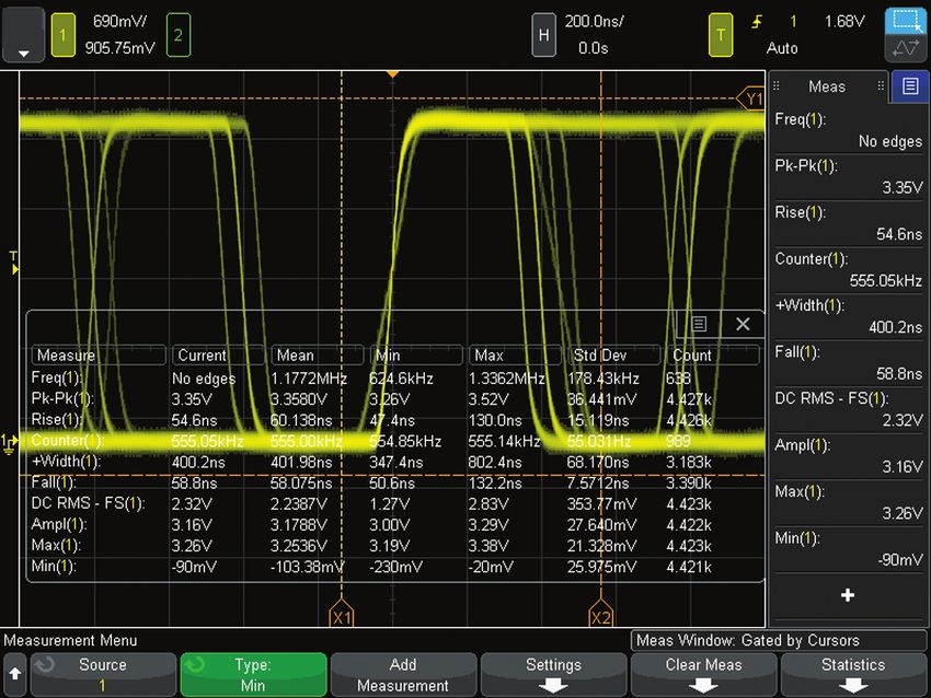
Table of Contents
Oscilloscope Experience Redefined: Experience the Speed,
       Usability, and Integration�������������������������������������������������������������������������������������������������������������������3
Experience the Speed������������������������������������������������������������������������������������������������������������������������������������5
Experience the Usability��������������������������������������������������������������������������������������������������������������������������������9
Experience the Integration�������������������������������������������������������������������������������������������������������������������������� 11
Other Key Productivity Tools����������������������������������������������������������������������������������������������������������������������� 14
Oscilloscope Experience Redefined������������������������������������������������������������������������������������������������������������22
Configuring Your InfiniiVision 4000 X-Series Oscilloscope������������������������������������������������������������������������ 24
InfiniiVision 4000 X-Series Performance Characteristics��������������������������������������������������������������������������26
License-only Bandwidth Upgrades and Measurement Applications���������������������������������������������������������35
Return-to-Keysight Service Center Bandwidth Upgrades�������������������������������������������������������������������������36
Keysight Oscilloscopes��������������������������������������������������������������������������������������������������������������������������������37

                                                Need more bandwidth, sampling rate, and analysis?
                                                Consider the Infiniium 6000 X-Series
                                                 – 1, 2.5, 4, and 6 GHz bandwidth
                                                 – 20 GSa/s sample rate
                                                 – Ultra-low noise at 1 mV/div
                                                 – 12.1-inch multi-touch capacitive display with gesture support
                                                 – Standard color grade, histogram, and enhanced FFT
                                                 – Optional jitter and real-time eye diagram analysis

                                                See www.keysight.com/find/6000X-Series for more details.

 Find us at www.keysight.com                                                                                                                       Page 2
Oscilloscope Experience Redefined:
Experience the Speed, Usability, and Integration
Imagine an oscilloscope that sees everything, triggers on
anything, has the ease-of-use of a tablet device…and grows with        4000 X-Series – Oscilloscope experience
your projects.                                                         redefined
                                                                       Key features:
The Keysight 4000 X-Series oscilloscopes are engineered for
                                                                        – Experience the speed:
next-generation performance, delivering waveform update rates
                                                                            – One million waveforms per second update rate
20 times faster than the competition to display the most signal
                                                                            – MegaZoom IV smart memory technology
detail. An industry-leading 12.1-inch capacitive touch screen
                                                                            – Standard segmented memory
with innovative hardware-based zone touch triggering provides
the most intuitive interface to get you answers faster. The 4000         – Experience the usability:
X-Series provides maximum investment protection with fully                 – Industry’s first capacitive touch screen
upgradable 7-instruments-in-1.                                             – Industry’s largest 12-inch display
                                                                           – Zone touch trigger
Experience the speed                                                     – Experience the integration:
Anomalies and elusive events are the toughest to debug. The                – Industry’s first 7 instruments in 1
4000 X-Series oscilloscope redefines your debugging experience             – Industry’s first fully upgradable oscilloscope
with MegaZoom IV smart memory technology. The industry-                       including bandwidth to 1.5 GHz
leading 1-million-waveforms-per-second update rate, means you              – Industry’s leading application solutions
see more of your signal behavior and can feel more confident in
your design.

Experience the usability
You may be surprised just how easy it is to use the InfiniiVision
4000 X-Series. A 12.1-inch capacitive touch screen − the
industry’s largest − works just like your favorite tablet or smart
phone, so debugging your devices is faster than ever before.
Innovative zone touch triggering makes triggering on anything
a snap. Just draw a box around signals of interest and the
oscilloscope triggers on them. So, if you can see it, you can
trigger on it.

Experience the integration                                           Figure 1. MegaZoom IV smart memory technology enables the speed,
The 4000 X-Series further redefines your oscilloscope experience     usability, and integration.
by integrating the capabilities of seven instruments in one:
oscilloscope channels, logic channels, digital voltmeter (DVM),
dual-channel WaveGen function/arbitrary waveform generator,
frequency response analyzer (Bode plots), 8-digit hardware
counter, and serial protocol analyzer including USB. All are
upgradable, including bandwidth, for the ultimate investment
protection.

                                                                     Figure 2. Take advantage of the Ultimate Bundle Software Package that
                                                                     enables ALL software applications (including serial decode, and for one
                                                                     low price (D4000BDLA).

 Find us at www.keysight.com                                                                                                           Page 3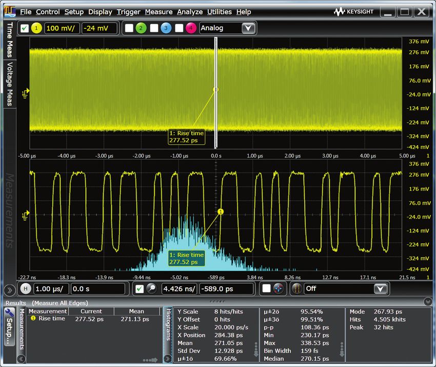
Oscilloscope Experience Redefined:
Experience the Speed, Usability, and Integration (Continued)
Overview of Keysight InfiniiVision X-Series oscilloscopes
InfiniiVision           6000 X-Series              4000 X-Series               3000T X-Series            2000 X-Series             1000 X-Series
Analog channels         2 or 4                     2 or 4                      2 or 4                    2 or 4                    2 or 4
Digital channels        16 (MSO models or          16 (MSO models or           16 (MSO models or         8 (MSO models or           External trigger can
                        upgrade)                   upgrade)                    upgrade)                  upgrade)                  be used as a 3rd digital
                                                                                                                                   channel for 2 channel
                                                                                                                                   model
Bandwidth               1, 2.5, 4, 6 GHz           200, 350, 500 MHz, 1,       100, 200, 350, 500 MHz,   70, 100, 200 MHz          50, 70, 100, 200 MHz
                                                   1.5 GHz                     1 GHz
Max sample rate         20 GSa/s                   5 GSa/s                     5 GSa/s                   2 GSa/s                   2 GSa/s
Max memory depth        4 Mpts                     4 Mpts                      4 Mpts                    1 Mpts                    2 Mpts (DSOX models)
Max waveform update     > 450,000 wfms/sec         > 1,000,000 wfms/sec        > 1,000,000 wfms/sec      > 200,000 wfms/sec        > 200,000 wfms/sec
rate                                                                                                                               (DSOX models)
Display                 12.1-inch, capacitive      12.1-inch, capacitive       8.5-inch, capacitive      8.5-inch                  7 inch
                        touch                      touch                       touch
Zone touch trigger      Standard                   Standard                    Standard                  No                        No
Voice control           Standard                   No                          No                        No                        No
WaveGen 20-MHz          Dual-channel AWG           Dual-channel AWG            Single-channel AWG        Single-channel function   Single-channel function
function/arbitrary      (option)                   (option)                    (option)                  (option)                  (on G models)
waveform generator
Integrated DVM          Standard                   Standard                    Standard                  Standard                  Standard
Integrated hardware     10-digit frequency,        5-digit frequency or        8-digit frequency,        5-digit frequency counter 5 digits
counter (standard)      period, or totalizer       period counter              period, or totalizer
                        counter                    (8 digits with external     counter
                                                   10 MHz clock reference)
Search and navigate    Standard, lister            Standard, lister            Standard, lister          Serial only               No
                       supported                   supported                   supported
Segment memory         Standard                    Standard                    Standard                  Standard                  Standard on DSO models
Mask limit test        Option                      Option                      Option                    Option                    Standard on DSO models
Measurement limit test Option                      Option                      Option                    No                        No
Serial protocol        I2C/SPI, UART/RS232,        I2C/SPI, UART/RS232,        I2C/SPI, UART/RS232,      I2C/SPI, UART, CAN/       I2C, UART (standard on
analysis options       CAN/CAN-dbc/CAN-FD/         CAN/CAN-dbc/CAN-FD/         CAN/CAN-dbc/CAN-FD/       LIN (will not operate     all models)
                       LIN/LIN symbolic,           LIN/LIN symbolic,           LIN/LIN symbolic,         simultaneously with       SPI, CAN/LIN (standard
                       SENT, FlexRay, I2S,         SENT, FlexRay, I2S,         SENT, FlexRay, I2S,       digital channels)         on DSO models)
                       MIL-STD1553, CXPI,          MIL-STD1553, CXPI,          MIL-STD1553, CXPI,
                       ARINC429, USB 2.0,          ARINC429, USB 2.0,          ARINC429, Manchester/
                       Manchester/NRZ, USB         Manchester/NRZ, USB         NRZ, USB PD
                       PD                          PD
Advanced analysis      Power analysis, USB 2.0     Power analysis, USB 2.0     Power analysis, HDTV      No                        FRA (Bode plots)
options                signal quality test, HDTV   signal quality test, HDTV   analysis, FRA, NFC
                       analysis, FRA               analysis, FRA, NFC
Color grade            Standard                    No                          No                        No                        No
Histogram              Standard                    No                          No                        No                        No
FFT                    Standard enhanced FFT       Standard enhanced FFT       Standard enhanced FFT     Standard                  Standard
Multi-domain analysis Gated FFT                    Gated FFT                   Gated FFT                 No                        No
Jitter analysis with   Option                      No                          No                        No                        No
clock recovery
Realtime eye diagram Option                        No                          No                        No                        No
Advanced math          Standard, display four      Standard, display one       Standard, display one     Standard, display one     No
                       functions simultaneously    function                    function                  function
Connectivity           Standard USB 2.0, LAN,      Standard USB 2.0, LAN,      Standard USB 2.0 (LAN/    Standard USB 2.0 (LAN/    Standard USB 2.0, LAN,
                       video (GPIB option), USB    video (GPIB option), USB    video/GPIB option), USB   video/GPIB option), USB   USB keyboard support
                       mouse and keyboard          mouse and keyboard          mouse and keyboard        keyboard support
                       support                     support                     support

 Find us at www.keysight.com                                                                                                                           Page 4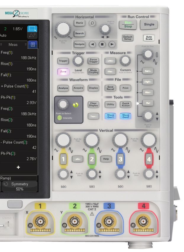
Oscilloscope Experience Redefined:
Experience the Speed
One million waveforms per second update rate
If you can’t see the problem, it is hard to troubleshoot it. With an
industry-leading one million waveforms per second update rate,
the InfiniiVision 4000 X-Series gives you the highest probability of
capturing random and infrequent events that you would miss on
an oscilloscope with a lower waveform update rate.

Powered by MegaZoom IV smart memory technology,
the InfiniiVision 4000 X-Series not only lets you see more
waveforms, but it has the uncompromised ability to find the most
difficult problems in your design. Unlike other oscilloscopes,
uncompromised ability means:
  – Always-fast, responsive operation
  – No slowdown with logic channels on
  – No slowdown with protocol decoding on
  – No slowdown with math functions turned on                              Figure 3. The 4000 X-Series captures a glitch occurring once in a million
  – No slowdown with measurements turned on                                waveform cycles.

What is waveform update rate and why is it important?
As oscilloscopes acquire data, process it, and plot it to the screen, there is inevitable “dead time,” or the time oscilloscopes miss
signals completely. In general, the faster the waveform update rate, the shorter the dead time. The shorter the dead time, the more
likely an oscilloscope is to capture anomalies and infrequent events. This is why it is critical to select an oscilloscope with a fast
waveform update rate.

Figure 4. Other vendor’s oscilloscope with 50,000 waveforms/second. A long dead time decreases your chances of
capturing infrequent events.

Figure 5. InfiniiVision 4000 X-Series with 1,000,000 waveforms/second. A short dead time increases your chances of
capturing infrequent events.

 Find us at www.keysight.com                                                                                                                  Page 5
Oscilloscope Experience Redefined:
Experience the Speed (Continued)
Keysight achieves this industry-leading waveform update rate with
MegaZoom IV smart memory technology
Traditionally, CPU processing was the major bottleneck for oscilloscope waveform
update rate and responsiveness. Typically, the CPU handles interpolations, logic channel
plotting, serial bus decoding, measurements and more, and the waveform update rate
drops dramatically as these features are turned on.

The InfiniiVision 4000 X-Series requires minimum support from a CPU, as most core
operations are handled by Keysight proprietary technology, the MegaZoom IV smart
memory ASIC. MegaZoom includes hardware serial decoders and hardware mask
limit testing capability, plots analog and digital data directly to the display, supports
GUI operation, and integrates additional instruments like the dual-channel WaveGen
function/arbitrary waveform generator.

                                                  MegaZoom IV ASIC

 Analog                                                                                                      Handware
 signals                                                                                                     accelerated
                                                                                                         (Measurements, Search)

                                       Acquisition
                                     memory manager                      Plotter
                                      (Segmented memory)
                                                                                                                  CPU
                                                                                                             (Math, I/O, GUI)

                                            DRAM                         DRAM
   16 digital                         (Acquisition memory)
    signals
                                                                           GUI

                                              Serial
                                             decoders                     Mask

                                            Trigger                    WaveGen
                                         (InfiniiScan and
                                            traditional)               Synthesis

Figure 6. The 4000 X-Series oscilloscopes’ uncompromised responsiveness, speed and waveform update rate is enabled by the MegaZoom IV, smart
memory ASIC. The CPU is not used for core waveform operations.

 Find us at www.keysight.com                                                                                                            Page 6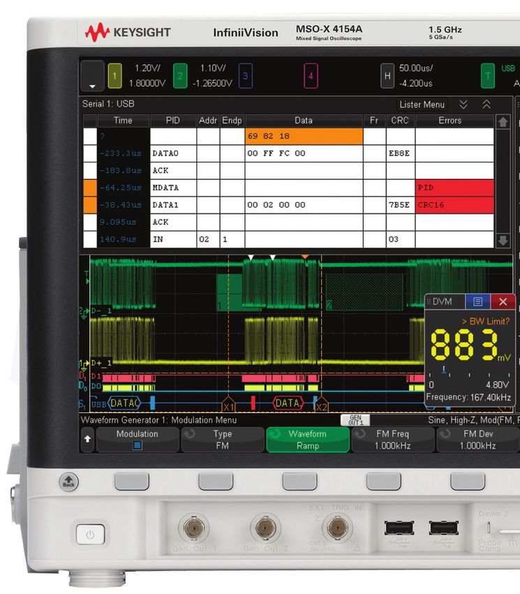
Oscilloscope Experience Redefined:
Experience the Speed (Continued)
Segmented memory: A smart and efficient way to
capture waveforms
Acquisition memory size is an essential oscilloscope specification
because it determines the amount of data you can capture in a
single acquisition. In general, longer memory is better. However,
no memory is always long enough to capture all the signals you
need, especially when capturing infrequent anomalies, data
bursts, or multiple serial bus packets. Segmented memory
acquisition lets you selectively capture and store important signal
activity without capturing unimportant signal idle time with the
time stamp of each segment relative to the first trigger event.
Segmented memory comes standard in the 4000 X-Series.

Figure 7 shows segmented memory successfully capturing 1,000
events in 3.27274 seconds. Traditional memory architecture
would require 2.7 Gpts of memory to accomplish the same result.
This memory is not available on any scope in the market.

                                                                      Figure 7. Segmented memory efficiently manages the memory to capture
                                                                      up to 1,000 segments of interest to you, making it an effective ultra-deep
                                                                      memory oscilloscope that can easily capture infrequent events and
                                                                      anomalies.

Segmented memory + serial decode
Segmented memory works in conjunction with serial protocol
decode. For example, by setting the trigger condition to “CAN
serial bus error,” segmented memory captures and stores only
CAN error packets and stitches together each segment for easy
viewing. You can quickly compare time tags in the event lister to
discover time intervals between errors.

                                                                      Figure 8. Segmented memory being used in conjunction with serial
                                                                      decode resulting in maximum insight into serial bus.

 Find us at www.keysight.com                                                                                                             Page 7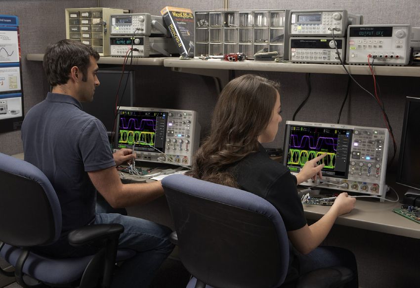
Oscilloscope Experience Redefined:
Experience the Speed (Continued)
Mask and measurement limit testing (option)
Whether you are performing pass/fail tests to specified standards
in manufacturing or testing for infrequent signal anomalies, mask
and measurement limit testing can be a valuable productivity
tool. The 4000 X-Series features powerful hardware-based mask
testing and can perform up to 270,000 tests per second. You
can select multiple test criteria, including the ability to run tests
for a specific number of acquisitions, a specified time, or until
detection of a failure.

With the optional measurement limit testing capability, you can
perform pass/fail testing based on user-defined maximum and
minimum limits on any parametric measurement that has been
selected and turned on. Stop-on-failure is also available.
                                                                         Figure 9. Mask testing evaluated > 22 M waveforms in just 2 minutes.

Search and navigation
The parametric and serial bus search and navigation feature
comes standard on the 4000 X-Series oscilloscopes. When you
are capturing long, complex waveforms using an oscilloscope’s
deep acquisition memory, manually scrolling through stored
waveform data to find specific events of interest can be slow and
cumbersome. With automatic search and navigation capability,
you can easily set up specific search criteria and then quickly
navigate to “found and marked” events. Available search criteria
include edges, pulse width (time-qualified), rise/fall times
(time-qualified), runt pulses (time-and level-qualified), frequency
peaks (FFT function, threshold and excursion qualified), and serial
bus frames, packets, and errors.
                                                                         Figure 10a. The 4000 X-Series was set up to capture data signals with
                                                                         various rise time edges. Using the search and navigation capability, the
                                                                         oscilloscope was able to find, mark (white triangles), and quickly navigate
                                                                         to 16 occurrences of “out of compliance” rise-time edges.

Figure 11. Using the error condition search, the 4000 X-Series quickly   Figure 10b. The 4000 X-Series was set up to capture clock signals for
found 5 places with a missing acknowledgment in an I²C serial bus. The   FFT analysis. Using the search and navigation capability, the scope
navigation feature moves between the errors and zooms automatically to   found, marked (white triangles) and quickly navigated to the first 11
show the error packet.                                                   frequency peaks occurrences. You can sort it in the order of frequency or
                                                                         amplitude.

 Find us at www.keysight.com                                                                                                                 Page 8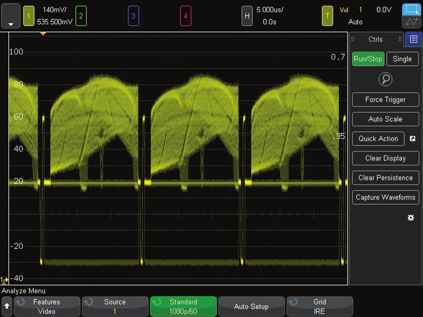
Oscilloscope Experience Redefined:
Experience the Usability
Industry’s largest 12.1-inch display
From the start of product development, we designed every aspect
of this oscilloscope for a touch interface. Large, easily touchable
targets on the industry’s largest 12.1-inch display with capacitive
touch screen technology mean operation is quick and natural, just
like your favorite tablet devices.
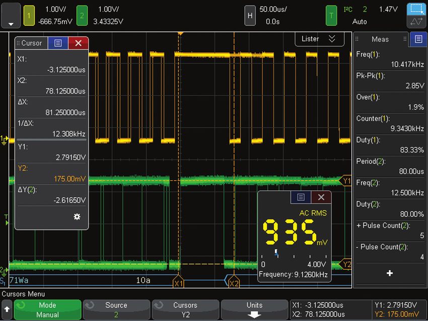
Capacitive touch screen technology
Capacitive touch screen technology provides enhanced
productivity. Use the alphanumeric pad for quick annotation,
place waveforms or cursors in exact positions and drag docking
panels across the screen to see more measurement information.
The 4000 X-Series offers three ways to access key menus
and features: touch GUI for those that prefer tablet or smart
phone touch interfaces, front panel keypads for the traditional Figure 13. See 10 measurements, cursor information, and the DVM
simultaneously by dragging the desired docking panel to any open area.
oscilloscope users, and Keysight pull down menu for users who
prefer Windows-like operations. The 4000 X-Series also offers a
“touch off” button as well as USB mouse and keyboard support.
Redefine your remote Web control oscilloscope experience. The
4000 X-Series not only supports traditional control via a PC Web
browser, but also supports remote control through popular tablet
devices.
Figure 14. Use the Keysight pull-down menu for Windows-like operation.
Figure 12. The industry’s largest 12.1-inch display and capacitive touch
screen technology with large, touchable targets.
Find us at www.keysight.com Page 9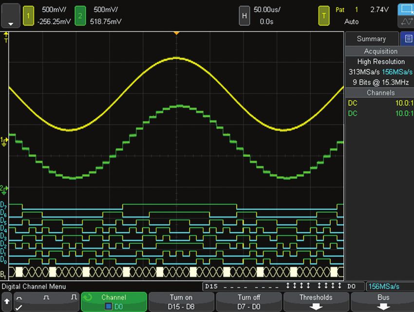
Oscilloscope Experience Redefined:
Experience the Usability (Continued)
Zone touch trigger
One of the biggest challenges of using an oscilloscope is setting
up an advanced trigger to isolate a signal of interest. While
advanced triggers are powerful features, zone touch trigger
provides a turnkey trigger solution.

You simply observe the signal of interest on the display, and
draw a zone (box) around it. What used to be hours of work can
now take just a few seconds. If you want to move your zones to
another location, just drag them over. The 4000 X-Series can be
set up to easily trigger on one or two zone boxes simultaneously
with either must intersect or must not intersect conditions.

Zone triggering does not compromise the waveform update
rate; the 4000 X-Series will still maintain an ultra-fast 200,000
waveforms per second or more, even with additional features
turned on. In other words, the oscilloscope that sees everything
can easily trigger on anything.

Zone touch trigger + segment memory: A whole
new experience
                                                                    Figure 15. When you see anomalies, all you have to do is
The combination of the industry’s only hardware-based zone          draw a zone box to trigger on them.
touch trigger with the 4000 X-Series’ segment memory simplifies
and enhances your debugging experience. In Figure 16, the 4000
X-Series has isolated and captured 1,000 metastable signals,
showing the critical bit errors over a 32-second time span at
5 GS/s sampling rate in the segment memory. The segment
memory also allows you to overlay all segments to identify the
worst-case signal.

                                                                    Figure 16. Combination of the zone touch trigger and
                                                                    segmented memory.

 Find us at www.keysight.com                                                                                               Page 10
Oscilloscope Experience Redefined:
Experience the Integration
Investment protection through a fully-upgradable 7-in-1 instrument
The InfiniiVision 4000 X-Series redefines the
oscilloscope experience with unprecedented
integration. This 7-in-1 instrument provides:
Serial protocol
– Oscilloscope
analysis
– 16 digital channels
– Serial protocol analyzer
– Dual-channel WaveGen 20 MHz function/
arbitrary waveform generator Oscilloscope
– 3-digit voltmeter (analog) channels
– Frequency response analysis (Bode Digital
voltmeter
plots) Logic channels
– 8-digit hardware counter with totalizer
Dual-channel
WaveGen
Figure 17. The 4000 X-Series provides the capabilities of five instruments
seamlessly integrated into one.
Multi-domain analysis: Time-correlate analog,
digital, and frequency domain signals
Viewing the frequency content of waveforms is greatly simplified
by a touch screen operation. Pop up keypads make inputting
start, stop, span and center frequency easy. And the new problem
solving feature called “gated FFT” lets you time correlate the
analog, digital, and frequency domain to aid in analysis and
debug. In addition, there are new capabilities for peak searching,
max and min hold and averaging of FFTs to increase dynamic
range.
When gated FFT is on, the oscilloscope goes into zoom mode.
The FFT analysis shown in the zoomed (bottom) window is taken
from the period of time indicated by the zoom box in the main
(top) window. In the gated FFT mode, touch and flick the zoom
box through the acquisition to investigate how the FFT analysis
changes over time, correlating the RF phenomenon with the Figure 18. Gated FFT successfully correlated the hopping of the FSK
analog and digital phenomenon. modulation with the analog and I2C control command.
Find us at www.keysight.com Page 11Oscilloscope Experience Redefined:
Experience the Integration (Continued)
Mixed signal oscilloscope (MSO): Integrated
16 digital channels
With an additional 16 integrated digital channels, you now have
up to 20 channels of time-correlated triggering, acquisition and
viewing on the same instrument. This is especially important
in today’s embedded designs with sophisticated digital control
circuitry. Unlike other oscilloscopes in this class, you can buy a
2- or 4-channel DSO and enable the 16 digital channels already in
the instrument at any time to make it an MSO. (DSOXPERFMSO)
Figure 19. Digital channels are captured and displayed time-correlated
with analog channels in MSOs or upgraded DSOs.
Serial protocol analysis: Hardware-based serial
protocol decode and triggering
Keysight InfiniiVision Series, including the new 4000 X-Series,
are the only oscilloscopes to use hardware-based serial
protocol decoding. Other vendors’ oscilloscopes use software
post-processing techniques to decode serial packets ⁄ frames,
and therefore have slow waveform and decode capture rates and
could miss critical events and errors due to a long dead-time.
Faster decoding with hardware-based technology enhances the
probability of capturing infrequent serial communication errors.
After capturing serial bus communication, you can easily
perform a search operation based on specific criteria and then
quickly navigate to bytes/frames of serial data that satisfy that
search criteria. The 4000 X-Series can decode two serial buses
Figure 20. Dual serial bus CAN and LIN decode and interleaved “lister“ display.
simultaneously using hardware-based decoding, and display the
captured data in a time interleaved “lister”display.
Serial protocol decoding can be used simultaneously with
segmented memory and zone touch triggering.
The 4000 X-Series supports: SENT, I2C, SPI, USB 2.0, RS232/
UART, CAN, CAN FD, LIN, FlexRay, CXPI, MIL-STD 1553, ARINC
429, I2S, user-definable Manchester, user-definable NRZ, and
USB PD. (See page 23)
Figure 21. USB 2.0 trigger, decode and “lister” display.
Find us at www.keysight.com Page 12Oscilloscope Experience Redefined:
Experience the Integration (Continued)
Dual-channel WaveGen 20-MHz function/arbitrary
waveform generator
The 4000 X-Series offers the industry’s first dual-channel,
integrated 20-MHz function/arbitrary waveform generator.
(DSOX4WAVEGEN2) The integrated generator provides stimulus
output of sine, square, ramp, pulse, DC, noise, sine cardinal
(sinc), exponential rise, exponential fall, cardiac, Gaussian pulse
and arbitrary waveforms (AWG) to your device under test. Signal
modulation capability is also available.
With AWG functionality, you can store waveforms from analog
channels or reference memory to the arbitrary memory and
output from WaveGen. Easily create and edit the waveform using
the built-in editor or Keysight’s BenchLink Waveform Builder
Basic software: www.keysight.com/find/33503. Figure 22. WaveGen sine wave output with and without added AM
modulation.
With dual channels, you can generate differential signals to:
output arbitrary clock and data signals to simulate serial buses,
create complex modulations (more than the standard modulation
feature), output IQ signals and more. The two channels can be
tracked together as well (identical frequency, amplitude, offset
and duty cycle).
3-digit voltmeter
The 4000 X-Series offers a standard integrated 3-digit voltmeter
(DVM) and 5-digit frequency counter (8-digit with external
reference) inside the oscilloscope. The voltmeter operates
through the same probes as the oscilloscope channels. However,
the DVM measurements are de-coupled from the oscilloscope
triggering system so that both the DVM and triggered
oscilloscope waveform capture can be made with the same Figure 23. WaveGen arbitrary waveform editing screen.
connection. The voltmeter results are always displayed, keeping
these quick characterization measurements at your fingertips.
Figure 25. DVM 3-digit
voltage and 5-digit frequency Figure 24. Dual channel WaveGen output of differential arbitrary signals.
measurements always at your Common mode is shown as a math function.
fingertips.
Find us at www.keysight.com Page 13Oscilloscope Experience Redefined:
Other Key Productivity Tools
Power measurements and analysis
When you are working with switching power supplies and power
devices, the Power Software Package (D4000PWRA) provides a
full suite of power measurements and analysis in the oscilloscope.
To learn more about power supply testing, go to
www.keysight.com/find/D4000PWRA.
Figure 26. Power quality measurement, one of many in the power
measurements application.
HDTV video triggering and analysis
Whether you are debugging consumer electronics with HDTV
or characterizing a design, Enhanced Video Analysis (optional)
provides support for a variety of HDTV standards for triggering
and analysis.
Figure 27. Triggering on 1080p HDTV signal analysis.
USB 2.0 signal quality analysis
In addition to triggering on and decoding low-speed, full-speed,
and hi-speed USB 2.0 signals (hi-speed trigger & decode require
a 1.0 or 1.5 GHz model), the optional USB Software Package
(D4000USBA) also supports USB 2.0 signal quality testing
(hi-speed tests require the 1.5 GHz model). The USB 2.0 signal
quality test with HTML pass/fail report generation includes
eye-diagram mask testing, jitter analysis, EOP bit-width, signaling
rate, edge monotonicity, and rise/fall times; all based on official
USB-IF algorithms embedded in the oscilloscope.
To learn more about USB signal quality testing, go to
www.keysight.com/find/D4000USBA.
Figure 28. Perform automatic signal quality testing on USB 2.0 low-
speed, full-speed, and hi-speed signals.
Find us at www.keysight.com Page 14Oscilloscope Experience Redefined:
Other Key Productivity Tools (Continued)
Frequency Response Analysis (Optional)
Frequency Response Analysis (FRA) is an often-critical
measurement used to characterize the frequency response
(gain and phase versus frequency) of a variety of today’s
electronic designs, including passive filters, amplifier circuits,
and negative feedback networks of switch mode power supplies
(loop response). InfiniiVision 4000 X-Series oscilloscopes use
the oscilloscope’s built-in waveform generator (WaveGen) to
stimulate the circuit under test at various frequency settings
and capture the input and output signals using two oscilloscope
channels. At each test frequency, the oscilloscope measures,
computes, and plots gain (20LogVout/Vin) and phase
logarithmically.
DSOXBODE bode plot training kit (optional)
The DSOXBODE Bode plot training kit consists of a series R-L-C
circuit board with a BNC input that attaches directly to the
output of the oscilloscope’s WaveGen function generator. There
are clearly labeled test points for probing VIN and BPFOUT
(bandpass filter output) or LPFOUT (low-pass filter output). Also
included with this training kit is a comprehensive tutorial and lab
guide that engineering students and professors can download.
The DSOXBODE Bode plot training kit is compatible with all
InfiniiVision 6000 X-Series oscilloscopes licensed with any
software option.
Educator’s oscillocope training kit
Teach your students what an oscilloscope is and how to perform
basic measurements with the Educator’s Oscilloscope Training
Kit. This complimentary kit includes training tools created
specifically for electrical engineering and physics undergraduate
students and professors. It contains an array of built-in
training signals, a comprehensive oscilloscope lab guide and
tutorial written specifically for undergraduate students and an
oscilloscope fundamentals PowerPoint ® slide set for professors
and lab assistants. Also available is an advanced triggering guide
to help even the most experienced oscilloscope users to get the
most out of their 4000 X-Series oscilloscope.
See www.keysight.com/find/dsoxedk for more information.
Figure 30. The Educators Training Kit helps both students and
experienced users quickly get up to speed on oscilloscope usage.
Find us at www.keysight.com Page 15Oscilloscope Experience Redefined:
Other Key Productivity Tools (Continued)
Advanced math analysis provides a variety of additional math
functions and comes standard on the 4000 X-Series. Additionally,
math functions can be nested to provide additional insight into
your designs. You can create up to four math functions, with one
resultant math function displayed at a time.
Operators
– Add, subtract, multiply, divide
Transforms
– Differentiate, integrate
– FFT
– Ax + B
– Squared, square root
– Absolute value
– Common logarithm, natural logarithm
Figure 31. A variety of advanced math functions are standard in the 4000
– Exponential, base 10 exponential
X-Series.
Filters
– Low-pass filter, high-pass filter
– Averaged value, smoothing, envelope
Visualizations
– Magnify
– Max hold, min hold
– Measurement trend Figure 32. Four math functions can be created and nested with one
– Chart logic bus timing, chart logic bus state resultant math function.
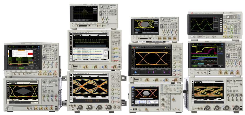
36 automatic measurements
Automatic measurements are the essential tool of an
oscilloscope. In order to make quick and efficient measurements,
the 4000 X-Series provides 36 powerful automatic measurements
and can display up to 10 at a time. Measurements can be gated
by auto select, main window, zoom window, or cursors.
Figure 33. Up to 10 automated measurements displayed simultaneously.
Measurements can be gated by cursors.
Find us at www.keysight.com Page 16Oscilloscope Experience Redefined:
Other Key Productivity Tools (Continued)
Reference waveforms
Store up to four waveforms in the scope’s non-volatile reference
waveform memory. Compare reference waveforms with live
waveforms, and perform post analysis and measurements on
stored data. You can also store waveforms on a removable
USB memory device in *.h5 format and recall them back into
oscilloscope’s reference waveform memory later. Save and/
or transfer waveforms to a PC as XY data pairs in a comma-
separated values format (*.csv) or store bitmap images and
transfer them to a PC for documentation purposes in a variety of
image formats.
Figure 34. Store and recall up to four reference waveforms.
Powerful probe solutions and compatibility
Get the most out of your 4000 X-Series scope, by using
Keysight’s complete family of innovative probes and accessories
for your application. The 4000 X-Series supports up to four active
probes simultaneously with its full AutoProbe interface. 1
All 4000 X-Series scopes come standard with a 700 MHz
bandwidth, 10 MΩ input passive probe per each channel and
gives you 700 MHz system bandwidth when used in conjunction
with the 4000 X-Series 1 GHz/1.5 GHz models.Also available
is the N2750A InfiniiMode differential probe and N2795A/96A
single-ended active probe for high signal fidelity measurements
without the high price. For ultra low current measurements,
the N2820A Series high-sensitivity current probes are the best
solution in the industry. For power rail measurements, the
N7020A Power Rail Probe provides the unmatched measurement
accuracy.
For the most up-to-date and complete information about Figure 35. N7020A Power Rail Probe is the industry’s only probe
Keysight’s probes and accessories, visit our Web site at designed and developed to solve your toughest power integrity problems.
www.keysight.com/find/scope_probes or refer to the InfiniiVision
Probes and Accessories data sheet with the Keysight literature
number 5968-8153EN.
1. Some restriction may apply. Contact Keysight for more details.
Find us at www.keysight.com Page 17Oscilloscope Experience Redefined:
Other Key Productivity Tools (Continued)
Localized front panel, GUI and help
Operate the oscilloscope in the language most familiar to you.
The graphical user interface, built-in help system, front panel
overlays, and user’s manual are available in 11 languages. During
operation, access the built-in help system just by pressing and
holding any button.
Figure 36. The 4000 X-Series and N2820A Series high-sensitivity current
probe measuring > 500 mA and < 1 mA current simultaneously.
Connectivity and LXI compatibility
Standard USB 2.0 hi-speed host (two on front, one on back) and
device (one on back) ports make PC connectivity easy. Operate
the scope from your PC and save/recall stored waveforms and
setup files via standard LAN (LXI IPv6 Extended Function).
Connect your projector or external monitor through VGA output,
standard with the 4000 X-Series, when sharing and presenting
screen information. An optional external GPIB-to-LAN adapter is
also available (N4865A).
The BV0004B oscilloscope control and automation PC-based
software (standard with the purchase of each InfiniiVision
X-Series oscilloscope) lets you control and visualize the 4000
X-Series and multiple measurements simultaneously. It lets you
Figure 37. BV0004B BenchVue.
build automated test sequences just as easily as you can with
the front panel. Save time with the ability to export measurement
data to Excel, Word and MATLAB in three clicks. Monitor and
control your 4000 X-Series with a mobile device from anywhere.
Simplify your testing with BenchVue software.
Learn more at www.keysight.com/find/BenchVue.
Find us at www.keysight.com Page 18Oscilloscope Experience Redefined:
Other Key Productivity Tools (Continued)
Virtual front panel
The 4000 X-Series’ innovative capacitive touch screen matches
perfectly with the latest tablet technologies. In addition to the
traditional virtual front panel remote operation through your
favorite PC Web browser, the 4000 X-Series supports remote
oscilloscope control from your tablet devices (and smart phones
with enough resolution). The tablet virtual front panel is identical
to the 4000 X-Series’ touch GUI so you can touch icons, draw
zone touch trigger zones and drag slide panels as if you are
sitting in front of the actual oscilloscope.
Figure 38. Tablet virtual front panel control.
Documentation and e-mail
Annotation becomes a simple task. Bring up the annotation Quick e-mail allows you to e-mail the data you want instantly
menu and start editing it using the keypad, and then drag it to to your inbox. Send out the screenshot, waveform data, or even
a USB signal quality test report. This removes the hassle of
the desired location. connecting your PC to your oscilloscope.
Figure 39(a). Annotation and keypad. Figure 39(b). E-mail configuration screen.
Find us at www.keysight.com Page 19Oscilloscope Experience Redefined:
Other Key Productivity Tools (Continued)
Infinium Offline oscilloscope analysis software
Keysight’s Infiniium Offline PC-based oscilloscope analysis
software (D9010BSEO) allows you to do additional signal viewing,
analysis and documentation tasks away from your oscilloscope.
Capture waveforms, save to a file, and recall the waveforms into
Infiniium Offline. The application supports a variety of popular
waveform formats from multiple oscilloscope vendors and
includes the following features: navigate, view, measurements,
analyze, view windows, documentation, and optional analysis
upgrades.
Figure 40. Infiniium Offline enables a variety of advanced signal analysis
while providing extensive, yet intuitive, waveform documentation.
Secure erase
The secure erase feature comes standard with all 4000 X-Series
models. At the press of a button, internal non-volatile memory
is clear of all setup, reference waveforms, and user preferences,
ensuring the highest level of security in compliance with National
Industrial Security Program Operation Manual (NISPOM) Chapter
8 requirements.
Find us at www.keysight.com Page 20Oscilloscope Experience Redefined:
Other Key Productivity Tools (Continued)
High-resolution mode for viewing signal details
To build more confidence in your designs, sometimes you need to
look into more signal detail than you can see with the standard
8-bit vertical resolution of the 4000 X-Series.
High-resolution mode offers additional resolution and insight into
the signal, without requiring a repetitive signal. Using real-time
boxcar averaging, high-resolution mode reduces random noise
and effectively increases vertical resolution, up to 12 bits. For
example, it achieves the 113 µVrms noise floor at 1 mV/div,
100 µs/div setting.
Figure 42. Getting 113 uVrms noise floor at 1 mV/div with the high
resolution mode.
Advanced parametric triggering
With today’s more complex signals, you often need to trigger
on complex signal conditions to synchronize the oscilloscope’s
acquisition on specific events. The 4000 X-Series oscilloscope
can trigger on the following conditions: edge, edge then edge,
pulse width (time-qualified), pattern, or, rise/fall time, Nth edge
burst, runt, setup and hold, video, and various serial buses
(optional).
Figure 43. Wide array of advanced parametric trigger modes.
Freeze display
Perhaps you need to share with others an infrequent event you
found. With the “freeze display” feature, you can keep intensity
information on the screen while the oscilloscope is stopped or
before saving a screen shot.
Figure 44. The “freeze screen” feature keeps the intensity-grading
information while stopping the waveform acquisition.
Find us at www.keysight.com Page 21Oscilloscope Experience Redefined
“Designed for touch.” Industry’s first and The class leading 1.5 GHz upgradeable
largest 12.1 inch capacitive touch screen bandwidth expands your application
to redefine your oscilloscope experience. coverage, including USB 2.0 hi-speed
The way an oscilloscope was meant to signal integrity testing.
be driven, with a designed-for-touch
interface.
The new zone touch trigger, if you can see
it, you can trigger on it by just drawing a
box.
5-in-1 instruments redefines the
integration experiences: oscilloscope
channels, digital channels, serial protocol
analysis, dual-channel WaveGen, and
DVM. All features are fully upgradeable,
including bandwidth.
Industry-leading coverage of serial
protocol including USB 2.0 trigger and
decode.
Industry’s first dual-channel WaveGen
function/arbitrary generator now allows
you to generate differential, clock and
data, two channel modulation, and IQ
signals. Modulation of any signal is also
included.
Both USB keyboard and mouse are
supported for additional ease of use.
Find us at www.keysight.com Page 22Industry-leading 1 million waveform per Docking panels with the capacitive touch screen add
second update rate minimizes the dead-time a new dimension of usability. See setup summary,
for maximum probability of capturing infrequent automatic measurements, cursor info, DVM, and
events and anomalies. navigation pane in any combination, anywhere on the
screen.
Standard advanced math and four cascade-able
math functions enable even the most sophisticated
signal analysis.
Display up to 10 measurements simultaneously,
without compromising other key info. 35 automatic
measurements can be gated by cursors.
Not a touch screen fan? Turn off the touch screen
from a front panel button if desired.
Independent knobs per channel for fast operation.
All front panel knobs are push-able for access to
common controls.
Standard segmented memory powered by
MegaZoom IV smart memory technology provides
intelligent capture of just the signal of interest.
Industry’s first integrated DVM. Simultaneous 1GHz bandwidth Four AutoProbe (active or current probes)
Asynchronous from the 4 analog across all 4 channels. are supported simultaneously for demanding
triggered waveforms. applications.
Find us at www.keysight.com Page 23Oscilloscope Experience Redefined:
Configuring Your InfiniiVision 4000 X-Series Oscilloscope
Step 1. Choose your bandwidth and number of channels
InfiniiVision 4000 X-Series scopes oscilloscopes
4022A 4024A 4032A 4034A 4052A 4054A 4104A 4154A
Bandwidth 1 (–3 dB) 200 MHz 350 MHz 500 MHz 1 GHz 1.5 GHz
Calculated rise time (10 to 90%) ≤ 1.75 ns ≤ 1 ns ≤ 700 ps ≤ 450 ps ≤ 300 ps
Input channels DSOX 2 4 2 4 2 4 4 4
MSOX 2 + 16 4 + 16 2 + 16 4 + 16 2 + 16 4 + 16 4 + 16 4 + 16
1. For example, if you chose 1 GHz, 4+16 channels, the model number will be MSOX4104A.
Step 2. Select hardware upgrades
Hardware Upgrade Description Model number to order
WaveGen Built-in dual-channel 20 MHz function/AWG waveform generator DSOX4WAVEGEN2
Enhanced Security Option Disable non-volatile memory, USB, LAN, and/or firmware upgrade DSOX4SECA
Step 3. Select licensed software
Licensed Software Description Model number to order
Embedded Software Package I2C, SPI, UART (RS232/422/485), I2S, and USB PD serial trigger & decode, plus D4000GENA
Measurement Limit Testing, Mask Limit Testing, Frequency Response Analysis (Bode
plots), and Enhanced Video Analysis
Automotive Software Package CAN (symbolic with .dbc file), CAN FD (symbolic with .dbc file), LIN (symbolic with .ldf D4000AUTA
file), FlexRay, SENT, CXPI, PSI5 (user-definable Manchester), and User-definable NRZ
serial trigger & decode, plus Measurement Limit Testing, Mask Limit Testing (CAN/CAN
FD mask files available to download) and Frequency Response Analysis (Bode plots)
Aero Software Package MIL-STD 1553 and ARINC 429 serial trigger & decode, plus Measurement Limit Testing, D4000AERA
Mask Limit Testing (standard mask files available to download), Frequency Response
Analysis (Bode plots), and Enhanced Video Analysis
USB Software Package1 USB 2.0 Low-, Full-, & Hi-speed, USB PD trigger & decode, plus USB 2.0 Signal Quality D4000USBA
Test, Jitter & Real-time Eye Analysis, Measurement Limit Testing, Mask Limit Testing,
and Frequency Response Analysis (Bode plots)
Power Software Package Power quality, current harmonics, switching loss, transient response, turn-on/off time, D4000PWRA
output ripple, efficiency, loop response, PSRR, etc., plus Measurement Limit Testing,
Mask Limit Testing and Frequency Response Analysis (Bode plots), and USB PD serial
trigger & decode
NFC Software Package NFC trigger and PC-based automated NFC test software D4000NFCA
Ultimate Bundle Software Package I2C, SPI, UART, I2S, CAN, CAN FD, LIN, FlexRay, CXPI, PSI5 (User-definable Manchester), D4000BDLA
User-definable NRZ, USB 2.0 low-, full-, & hi-speed 1, USB PD, MIL-STD 1553, and
ARINC 429 serial trigger & decode, plus USB 2.0 Signal Quality Test 2, Power Analysis,
Measurement Limit Testing, Mask Limit Testing, Frequency Response Analysis (Bode
plots), Enhanced Video Analysis, NFC trigger & automated test software
1. USB 2.0 hi-speed signal trigger and decode on ≥ 1.0-GHz models only.
2. USB 2.0 hi-speed signal quality tests supported on 1.5-GHz models only.
Find us at www.keysight.com Page 24Oscilloscope Experience Redefined: Configuring Your InfiniiVision 4000 X-Series Oscilloscope (Continued) Step 4. Choose your probes – For a complete list of compatible probes, visit www.keysight.com/find/scope_probes Probes 4000 X-Series N2894A passive probe 700 MHz, 10:1, 10 MΩ Included standard. 1 per channel N2756A 16 digital channel MSO cable Included on MSOX models and DSOXPERFMSO 10076B high-voltage passive probe 250 MHz 4 kV Optional N2795A active single-ended probe 1-GHz 1-pF 1-MΩ with AutoProbe Optional N2796A active single-ended probe 2-GHz 1-pF 1-MΩ with AutoProbe Optional N2750A InfiniiMode differential probe 1.5-GHz 700-fF 200-kΩ with AutoProbe Optional N2797A extreme temperature active probe 1.5-GHz 1-pF 1-MΩ with AutoProbe Optional N2790A differential active probe 100 MHz, ± 1.4 kV with AutoProbe Optional N2791A differential active probe 25 MHz, ± 700 V Optional N2818A differential active probe 200 MHz, ± 20 V Optional N2819A differential active probe 800 MHz, ± 15 V Optional 1147B AC/DC current probe 50 MHz 15 A with AutoProbe Optional N2893A AC/DC current probe 100 MHz 15 A with AutoProbe Optional N2820A 2-channel high-sensitivity current probe 50 uA to 5 A Optional N7020A power rail probe 2-GHz, 1:1, 50 kΩ, ± 24 V offset range Optional N2805A high voltage differential probe, 200 MHz, ± 100 V (DC + peak AC), 50:1, 4-MΩ, 4 pF Optional N2804A high voltage differential probe, 300 MHz, ± 300 V (DC + peak AC), 100:1, 4-MΩ, 4 pF Optional N7040A 23 MHz, 3 kA, AC current probe Optional N7041A 30 MHz, 600 A, AC current probe Optional N7042A 30 MHz, 300 A, AC current probe Optional N7026A 150 MHz, 40 Apk, AC/DC high-sensitivity current probe with AutoProbe Optional Step 5. Choose your accessories Recommended accessories and PC software 4000 X-Series Bode plot training kit DSOXBODE Rack mount kit N2763A Soft carrying case N2733B Hard copy manual N6455A Step 6. Calibration plans and additional productivity software Calibration D/MSOX4000-A6J ANSI Z540-1-1994 calibration Optional D/MSOX4000-AMG Calibration + Uncertainties + Guardbanding (Accredited) Optional BV0004B BenchVue Oscilloscope Application PC Software Standard 33503A BenchLink Waveform Builder Pro and Basic PC Software Optional D9010BSEO Infiniium Offline Oscilloscope Analysis PC Software Optional D9010UDAA User-definable Application (UDA) Software Optional 89601B (version Vector Signal Analyzer (VSA) Software Optional 20.20 and higher) Find us at www.keysight.com Page 25
Configure your InfiniiVision 4000 X-Series Oscilloscope (Continued)
Flexible Software Licensing and KeysightCare Software Support
Subscriptions                                                                                    KeysightCare Software
Keysight offers a variety of flexible licensing options to fit your needs and budget.            Support Subscription
Choose your license term, license type, and KeysightCare software support subscription.          provides peace of mind
                                                                                                 amid evolving technologies.
License Terms                                                                                     – Ensure your software is
 – Perpetual – Perpetual licenses can be used indefinitely.                                         always current with the
 – Time-based – Time-based licenses can be used through the term of the license only                latest enhancements and
   (6, 12, 24, or 36 months).                                                                       measurement standards.
                                                                                                  – Gain additional insight into your
License Types                                                                                       problems with live access to our
 – Node-locked – All software licenses for the InfiniiVision 6000 X-Series oscilloscopes            team of technical experts.
   are node-locked to the oscilloscope                                                            – Stay on schedule with fast
                                                                                                    turnaround times and priority
KeysightCare Software Support Subscriptions                                                         escalations when you need
                                                                                                    support.
Perpetual licenses are sold with a 12 (default), 24, 36, or 60-month software support
subscription. Support subscriptions can be renewed for a fee after that.

Time-based licenses include a software support subscription through the term of the
license.

Selecting your license:
Step 1. Choose your Software Package (Ex: D4000BDLA).
Step 2.	 Choose your license term: perpetual or time-based.
Step 3.	 Depending on the license term, choose your support subscription duration.

Examples
 If you selected:              Your quote will look like:
                               Part Number      Description
 D4000BDLA node-locked         D4000BDLA        Ultimate Bundle Software Package for 4000
 perpetual license with        R-B5K-001-A      X-Series
 a 12-month support            R-B6K-001-L      Node-locked perpetual license
 subscription                                   12-month software support subscription
 D4000AUTA node-locked         D4000AUTA        Automotive Software Package for 4000 X-Series
 6-month time-based license    R-B4K-001-F      6-month time-based, node-locked license with
                                                standard 6-month software support subscription

 Find us at www.keysight.com                                                                                                   Page 26
Oscilloscope Experience Redefined:
InfiniiVision 4000 X-Series Performance Characteristics
DSO and MSO 4000 X-Series oscilloscopes
4000 X-Series specification overview
4022A 4024A 4032A 4034A 4052A 4054A 4104A 4154A
Bandwidth 1 (–3 dB) 200 MHz 350 MHz 500 MHz 1 GHz 1.5 GHz 3
All-channel real-time bandwidth 200 MHz 350 MHz 500 MHz 1 GHz 1 GHz
Calculated rise time (10 to 90%) ≤ 1.75 ns ≤ 1 ns ≤ 700 ps ≤ 450 ps ≤ 300 ps
Input channels DSOX 2 4 2 4 2 4 4 4
MSOX 2 + 16 4 + 16 2 + 16 4 + 16 2 + 16 4 + 16 4 + 16 4 + 16
Maximum sample rate 5 GSa/s half channel, 2.5 GSa/s all channel
Maximum memory depth 4 Mpts half channels, 2 Mpts all channels
Display size and type 12.1-inch high-definition capacitive touch display
Waveform update rate > 1 million waveforms per second
System bandwidth with N2894A standard 200 MHz 200 MHz 350 MHz 350 MHz 500 MHz 500 MHz 700 MHz 700 MHz
passive probe
System analog channels
Hardware bandwidth limits Approximately 20 MHz (selectable)
Input coupling AC, DC
Input impedance Selectable: 1 MΩ ± 1% (16 pF), 50 Ω ± 1.5%
Input sensitivity range 200 MHz ~ 500 MHz models: 1 mV/div to 5 V/div 2 (1 MΩ and 50 Ω)
1 and 1.5 GHz models: 1 mV/div to 5 V/div 2 (1 MΩ), 1 mV/div to 1 V/div (50 Ω)
Vertical resolution 8 bits (measurement resolution is 12 bits with averaging)
Maximum input voltage 1 MΩ 135 Vrms; 190 Vpk
Probing technology allows testing of higher voltages. For example, the included N2894A
10:1 probe supports testing up to 300 Vrms
Use this instrument only for measurements within its specified measurement category (not
rated for CAT II, III, IV). No transient overvoltage allowed
50 Ω 50 Ω: ≤ 5 Vrms max
DC vertical gain accuracy 1 ± 2.0% full scale 2
DC vertical offset accuracy ± 0.1 div ± 2 mV ± 1% of offset setting
Channel-to-channel isolation 200 MHz~1 GHz ≥ 40 dB from DC to maximum specified bandwidth of each model
1.5 GHz ≥ 40 dB from DC to 1 GHz, ≥ 35 dB from 1 to 1.5 GHz
Offset range ± 5 V (< 10 mV/div), ± 20 V (10 to 200 mV/div), ± 75 V (> 200 mV/div)
Vertical system digital channels
Digital input channels 16 digital (D0 to D15. Pod 1: D7 ~ D0, Pod 2: D15 ~ D8)
Thresholds Threshold per pod
Threshold selections TTL (+1.4 V), 5 V CMOS (+2.5 V), ECL (–1.3 V), user-defined (selectable by pod)
User-defined threshold range ± 8.0 V in 10 mV steps
Maximum input voltage ± 40 V peak CAT I
Threshold accuracy 1 ± (100 mV + 3% of threshold setting)
Maximum input dynamic range ± 10 V about threshold
Minimum voltage swing 500 mVpp
Input impedance 100 kΩ ± 2% at probe tip
Input capacitance ~8 pF
Vertical resolution 1 bit
1. Denotes warranted specifications, all others are typical. Specifications are valid after a 30-minute warm-up period and ± 10 °C from firmware calibration
temperature.
2. 1 mV/div and 2 mV/div is a magnification of 4 mV/div setting. For vertical accuracy calculations, use full scale of 32 mV for 1 mV/div and 2 mV/div sensitivity
setting.
3. 1.5 GHz real time bandwidth in half-channel mode or full channel equivalent time mode.
Find us at www.keysight.com Page 27Oscilloscope Experience Redefined:
InfiniiVision 4000 X-Series Performance Characteristics (Continued)
Horizontal system analog channels
4022A 4024A 4032A 4034A 4052A 4054A 4104A 4154A
Time base range 2 ns/div to 50 s/div 1 ns/div to 50 s/div 500 ps/div to 50 s/div
Time base accuracy 1 ± 10 ppm
Time base delay time range Pre-trigger Greater of 1 screen width or 200 μs (400 μs in interleaving mode)
Post-trigger 1 to 500 s
Channel-to-channel deskew range ± 100 ns
Δ Time accuracy (using cursors) ± 0.001% of reading ± 0.16% screen width ± 30pS
Modes Main, zoom, roll, XY
XY On channels 1 and 2 only. Z Blanking on Ext Trigger Input, 1.4 V threshold
Bandwidth: Maximum bandwidth. Phase error at 1 MHz: < 0.5 degree
Time base: 200 ns/div to 50 ms/div
Horizontal system digital channels
Minimum detectable pulse width 2 ns
Channel-to-channel skew 2 ns (typical); 3 ns (maximum)
Acquisition system
4022A 4024A 4032A 4034A 4052A 4054A 4104A 4154A
Maximum analog channels sample rate 5 GSa/s half channel interleaved, 2.5 GSa/s all channels
Analog channels equivalent sample rate N/A 128 Gsa/s
Maximum analog channels record length 4 Mpts half channel interleaved, 2 Mpts all channel
Maximum digital channels sample rate 1.25 GSa/s
Maximum digital channels record length 2 Mpts (with digital channels only)
Modes Normal Default mode
Peak detect Capture glitches as narrow as 200 ps at all time base settings
Averaging Selectable from 2, 4, 8, 16, 64, ... to 65,536
High Real-time boxcar averaging reduces random noise and effectively increases vertical resolution
resolution – 12 bits: ≥ 50 μs/div
– 11 bits: ≥ 20 μs/div
– 10 bits: ≥ 10 μs/div
– 9 bits: ≥ 5 μs/div
Segmented Segmented memory optimizes available memory for data streams that have long dead times
between activity. Maximum segments = 1000. Re-arm time = 1 μs (minimum time between trigger
events). Re-arm time when used with the zone touch trigger = 65 μs or faster (typical)
Roll Displays the waveform moving across the screen from right to left. Available at the time base
50 ms/div or slower
Digitizer Allows independent selection of sample rate and memory depth
Equivalent 1 GHz and 1.5 GHz models only. 7.8 ps fine interpolator resolution yields a maximum effective
time sample rate of 128 GSa/s
1. Denotes warranted specifications, all others are typical. Specifications are valid after a 30-minute warm-up period and ± 10 °C from firmware calibration
temperature.
Find us at www.keysight.com Page 28Oscilloscope Experience Redefined:
InfiniiVision 4000 X-Series Performance Characteristics (Continued)
Trigger system
Trigger sources Analog channel (1 ~ 4), digital channel (D0 ~ D15), line, external, WaveGen (1, 2, or Mod)
(FM/FSK)
Trigger modes Normal Requires trigger event for oscilloscope to trigger
Auto Triggers automatically in absence of trigger event
Single Front panel button that triggers only once on a trigger event. Press [Single] button again
for oscilloscope to find another trigger event, or press [Run] front-panel button to trigger
continuously in either auto or normal mode
Force Front panel button that forces a trigger
Trigger coupling DC DC coupled trigger
AC AC coupled trigger, cutoff frequency: < 10 Hz (internal); < 50 Hz (external)
HF reject High-frequency reject, cutoff frequency ~ 50 kHz
LF reject Low-frequency reject, cutoff frequency ~ 50 kHz
Noise reject Adds hysteresis to the trigger circuitry. Selectable OFF or ON, decreases sensitivity 2x
Trigger holdoff range 40 ns to 10.00 s
Trigger sensitivity (internal) 1 200 MHz ~ 1 GHz < 10 mV/div: greater of 1 div or 5 mV; ≥ 10 mV/div: 0.6 div
1.5 GHz DC to 1 GHz: < 10 mV/div: Greater of 1 div or 5 mV; ≥ 10 mV/div: 0.6 div
1 to 1.5 GHz: < 10 mV/div: Greater of 1.5 div or 5 mV; ≥ 10 mV/div: 1.0 div
Trigger sensitivity (external) 1 ± 1.6 V 40 mVpp DC to 100 MHz, 70 mVpp 100 to 200 MHz
±8V 200 mVpp DC to 100 MHz, 350 mVpp 100 to 200 MHz
Trigger level range Any channel ± 6 div from center screen
External 8 V range = ± 8 V, 1.6 V range = ± 1.6 V
1. Denotes warranted specifications, all others are typical. Specifications are valid after a 30-minute warm-up period and ± 10 °C from firmware calibration
temperature.
Find us at www.keysight.com Page 29You can also read