6888 in-Situ Combustion O2 Analyzer - Installation/Start-up Manual
←
→
Page content transcription
If your browser does not render page correctly, please read the page content below

Installation/Start-up Manual
                             CMB_MAN_ABR_106-6888QS_6888
                                                June 2014

6888 in-Situ Combustion O Analyzer
                         2
Installation/Start-up Manual                                                                                   Table of Contents
CMB_MAN_ABR_106-6888QS_6888                                                                                                     June 2014

Contents
              Section 1: General Information
                     Essential Instructions ...............................................................................................4
                     Overview .................................................................................................................6
                     System Configurations
                              Transmitter Probe, Only .............................................................................6
                              Standard Housing Transmitter Probe plus 6888Xi Electronics ....................6
                              Transmitter Probe and 6888Xi with Flame Safety Interlock.........................7
                              Transmitter Probe w/Integral Autocal, 6888Xi, and
                              HART Communications ..............................................................................7
                              Transmitter Probe w/Integral Autocal and
                              FOUNDATION Fieldbus (FF) Communications ............................................7
                              Direct Replacement (DR) Probe, w/Traditional Architecture
                              6888Xi Electronics .....................................................................................7
                              Wireless Capability.....................................................................................7
              Section 2: Typical System Package
                     Technical Support Hotline .......................................................................................8
              Section 3: 6888A Product Matrix
                     6888A O2 Transmitter ..............................................................................................9
                     6888Xi Advanced Electronics ................................................................................11
              Section 4: Specifications
                     Transmitter/DR Probe
                             Measurement Specifications ....................................................................12
                             Environmental Specifications ...................................................................12
                     6888Xi
                             Measurement Specifications ....................................................................12
                             Installation Specifications Xi with Transmitter Probe ................................14
                             Installation Specifications for Traditional Architecture Xi for use
                             with DR or other Probe.............................................................................15
              Section 5: Installation
                     Mechanical installation
                              6888A Probe Installation..........................................................................16
                              Drip Loop and Insulation Removal ............................................................20
                              6888Xi Advanced Electronics ...................................................................21
                              Wall/Surface and Pipe Mount ...................................................................22
                              Panel Mount.............................................................................................23
                     Electrical
                              Wiring for 6888 Transmitter Probe only (no Xi Electronics) ......................25
                              Standard Housing Transmitter Probe plus 6888Xi Electronics ..................27
                              Transmitter Probe w/Single-channel Xi and Flame Safety Interlock ..........30
                              Transmitter Probe w/Integral Autocal and HART communications ...........34
                              Transmitter Probe w/Integral Autocal and FOUNDATION
                              Fieldbus communications ........................................................................38
                              Traditional Architecture System w/Direct Replacement Probe
                              (no Electronics inside) ..............................................................................42
                              Existing Yokogawa Electronics..................................................................46
                              Traditional Architecture Cable Connections .............................................48

2                                                                                                                          Table of Contents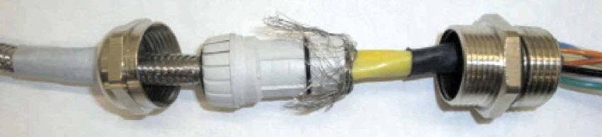
Table of Contents                                                                            Installation/Start-up Manual
June 2014                                                                                   CMB_MAN_ABR_106-6888QS_6888

Contents
                    Section 7: Pneumatic Installation
                         Reference Air Package ........................................................................................50
                    Section 8: Power Up Procedures
                         6888 Transmitter without 6888Xi ......................................................................51
                         6888 Transmitter w/Single/Dual Channel or Single Channel & Flame Safety
                         Interlock 6888Xi.................................................................................................52
                         6888 Direct Replacement Probe (no Electronics inside) w/Traditional
                         Architecture 6888Xi...........................................................................................52
                         6888Xi Quick Start Wizard .................................................................................53
                         Re-initiating 6888Xi Wizard................................................................................53
                    Section 9: Calibration
                         6888 O2 Analyzer................................................................................................54
                    Section 10: Menu Trees
                         HART 6888Xi......................................................................................................58
                         HART 375/475 Communicator...........................................................................64
                         FOUNDATION Fieldbus 6888Xi...........................................................................68
                         FOUNDATION Fieldbus 375/475 Communicator ...............................................74
                    Section 11: Safety Data
                         Safety Data.........................................................................................................82
                    Section 12: Return of Material
                         Returning Material .............................................................................................83
                    Section 13: EC Declaration of Conformity
                         Returning Material .............................................................................................84

Table of Contents                                                                                                                                 3
Installation/Start-up Manual Essential Instructions
CMB_MAN_ABR_106-6888QS_6888 June 2014
Essential Instructions
Read this page before proceeding
Emerson Process Management designs, manufactures and tests its products to meet many
national and international standards. Because these instruments are sophisticated
technical products, you MUST properly install, use, and maintain them to ensure they
continue to operate with-in their normal specifications. The following instructions MUST
be adhered to and integrated into your safety program when installing, using, and
maintaining Rosemount Analytical products.Failure to follow the proper instructions may
cause any one of the following situations to occur: Loss of life; personal injury; property
damage; damage to this instrument; and warranty invalidation.
• Read all instructions prior to installing, operating, and servicing the product.
• If you do not understand any of the instructions, contact your Emerson Process
Management representative for clarification.
• Follow all warnings, cautions, and instructions marked on and supplied with the
product.
• Inform and educate your personnel in the proper installation, operation, and
maintenance of the product.
• Install your equipment as specified in the Installation Instructions of the appropriate
Instruction Manual and per applicable local and national codes. Connect all products
to the proper electrical and pressure sources.
• To ensure proper performance, use qualified personnel to install, operate, update,
program, and maintain the product.
NOTICE
This manual concentrates on the installation, start-up, calibration, and operation of this
product. There is also a more comprehensive manual that also covers troubleshooting,
maintenance, repair, and spare parts identification.
• When replacement parts are required, ensure that qualified people use
replacement parts spec-ified by Emerson Process Management. Unauthorized
parts and procedures can affect the product's performance, place the safe
operation of your process at risk, and VOID YOUR WARRANTY. Look-alike
substitutions may result in fire, electrical hazards, or improper operation.
• Ensure that all equipment doors are closed and protective covers are in place,
except when maintenance is being performed by qualified persons, to prevent
electrical shock and personalinjury. The information contained in this document
is subject to change without notice.
The information contained in this document is subject to change without notice.
NOTICE
The 375 Field Communicator must be upgraded to System Software 2.0 with Graphic
License for operation with the 6888A O2Transmitter. The AMS software must be upgraded
to AMS 8.0 or above. Contact Emerson Process Management’s Global Service Center (GSC)
at 1-800-833-8314 to upgrade the 375 Field Communicator software to System Software
2.0 with Graphic License.
4 Essential InstructionsEssential Instructions Installation/Start-up Manual
June 2014 CMB_MAN_ABR_106-6888QS_6888
Essential Instructions
Symbols
:
:
:
:
Note: If the equipment is used in a manner not specified by the manufacturer, the
protection provided by the equipment may be impaired.
Definitions
The following definitions apply to WARNINGS, CAUTIONS, and NOTES found throughout
this publication.
WARNING
Highlights an operation or maintenance procedure, practice, condition, statement, etc.
If not strictly observed, could result in injury, death, or long-term health hazards of
personnel.
CAUTION
Highlights an operation or maintenance procedure, practice, condition, statement, etc.
If not strictly observed, could result in damage to or destruction of equipment, or loss o
effectiveness.
NOTICE
Highlights an essential operating procedure, condition, or statement.
Essential Instructions 5Installation/Start-up Manual General Information
CMB_MAN_ABR_106-6888QS_6888 June 2014
General Information
Overview
The 6888 is Rosemount Analytical’s latest combustion flue gas oxygen analyzer. This
product is intended for measuring the flue gases resulting from any combustion process.
It utilizes the same heated sensing technology as the O2 sensors found in most
automobiles. Contact Rosemount Analytical’s technical support group at 800-433-6076
for any applications other than measuring combustion flue (exhaust) gases.
This product utilizes an “in situ” sensor, i.e. the sensor is placed at the end of a probe, and
the probe extends directly into the flue gas duct or stack at a given length. The sensor is
like a thermocouple, generating it’s own millivolt signal based on the difference between a
reference gas (ambient or instrument air – always 20.95% O2), and the flue gases being
measured. There are several different arrangements of probes, electronics, and features
that are explained below, and in the wiring diagrams.
An optional 6888 Xi with HART communications provides convenient operator interface
for set-up, calibration, and diagnostics. HART communications is still present when using
the 6888Xi.
System Configurations
Transmitter Probe, Only
The 6888 probe has the electronics in the blue housing that controls the heater
temperature, and also amplifies the raw O2 millivolt signal to a linear 4-20 mA. The
4-20 mA signal lines can be run directly to the control room, and also powers the
transmitter electronics. As with most other Rosemount transmitters measuring pressure,
temperature, and flow, set-up is conducted through HART communications via a 475
handheld communicator, or via Asset Management
Solutions (AMS).
Standard Housing Transmitter Probe plus
6888Xi Electronics
The 6888Xi electronics serve as a local operator interface unit, with a back-lit display and
keypad. It is capable of two channels, serving two 6888 probes. The 6888Xi also carries these
optional advanced features:
• Fully automatic calibration. Requires Xi 02 Cal Auto calibration system.
• Loss-of flame contact for powering down the heater in the event of a flame-out
condition in a furnace.
• Heaterless operation at process temperatures above 550°C. This feature will also
permit operation above the heater set point of 736°C. Sensing cell life will be
shortened by operation above 800°C, however.
• Plugged diffuser diagnostic operates by measuring the return-to-process rate after
calibration gas has been stopped. This feature also includes auto gas switching
when the reading settles out versus waiting for configured gas flow time to expire.
• Stoichiometer – If a furnace goes into a reducing condition (zero % O2), this feature will
determine how far.
• Programmable reference – Permits more accurate readings at near-ambient O2
levels (20.95% O2).
6 General InformationGeneral Information Installation/Start-up Manual
June 2014 CMB_MAN_ABR_106-6888QS_6888
General Information
Standard Housing Transmitter Probe plus
6888Xi Electronics
• A “cal check” capability. New calibration values are not automatically stored after
a calibration. An accept/reject calibration feature can be enabled or disabled so
that the technician or operator can decide to accept or reject a potentially large
change in calibration values.
• Tolerance Check that will alarm if the wrong test gases are being used, or if a bottle
runs out in the middle of a calibration. Care must be taken to ensure gas 1 and gas
2 calibration gases are properly configured if the tolerance check feature is
enabled.
Transmitter Probe and 6888Xi with Flame safety interlock
A flame safety interlock by Emerson Process Management is available for heater power
disconnect whenever there is a loss of the process flame or a heater runaway condition
(heater over-temperature) in the O2 Probe. This input is internally powered by the 6888Xi
and is actuated via a dry contact output from the user’s flame scanner. A closed contact
indicates a flame is present. An open contact indicates a loss of flame. This feature is also
available with the Integral autocal housing.
Transmitter Probe with Integral Autocal, 6888Xi,
and HART communications
This probe contains gas-switching solenoids so that the 6888Xi electronics can control the
introduction of calibration gases. Calibrations can be initiated via a calibration
recommended diagnostic, time since last calibration, manually via external dry contact,
HART communications, or from the 6888Xi local operator interface keypad. The integral
autocal feature can only be implemented when the probe is used with a 6888Xi.
Transmitter Probe with Integral Autocal and
FOUNDATION Fieldbus (FF) communications
This probe contains gas-switching solenoids that can control the introduction of calibration
gases for calibration. Calibrations can be initiated automatically via a calibration
recommended diagnostic, time since last calibration, or manually via optional Xi keypad, FF
communications via the 475 communicator, or AMS console. Unlike the HART transmitter
electronics, the FF version can execute automatic calibrations either with or without the
optional 6888 Xi electronics. Likewise, advanced features can be implemented either with
or without the optional Xi.
Direct Replacement (DR) Probe, with Traditional
Architecture 6888Xi electronics
Here there are no electronics inside the probe head, so the raw sensor signals for the heater
thermocouple and zirconium oxide O2 sensor are sent to a remote 6888Xi Electronics. The
6888 Traditional Architecture electronics will also directly apply power to the probe heater
in order to maintain the correct sensor temperature. This arrangement calls for a
7- conductor cable to carry this power and the sensor signals. Maximum length for this cable
is 200 feet. This probe will also operate on previous Westinghouse/Rosemount electronics
(World Class and Oxymitter), as well as many competitive electronics.
Wireless Capability
It should be noted that both the transmitter electronics in the head of the probe and the
6888Xi electronics communicate over HART communications, and can implement wireless
communications via our Smart Wireless THUM adapter.
General Information 7Installation/Start-up Manual Typical System Package
CMB_MAN_ABR_106-6888QS_6888 June 2014
Typical System Package
Quick Start
Manual Full Instruction
Optional 6888Xi Manual DVD
Advanced Electronics
Optional Mounting or
Adapter Plate
6888A Probe with Standard
Terminations/Electronics
Housing
Optional Traditional
Architecture Cable
6888A Integral Autocal Housing
Optional Reference
& Calibration Gas
Accessories
Technical Support Hotline
For assistance with technical problems, please call the Customer Support Center (CSC).
• 1-RAI-AND-U (1-855-724-2638)
• 1-440-914-1261
In addition to the CSC, you may also contact Field Watch. Field Watch coordinates Emerson
Process Management’s field service throughout the U.S. and abroad.
• 1-800-654-RSMT (1-800-654-7768)
Emerson Process Management may also be reached via the Internet through e-mail and
the World Wide Web
• e-mail: GAS.CSC@emerson.com
• World Wide Web: www.raihome.com
8 Typical System PackageProduct Matrix Installation/Start-up Manual
June 2014 CMB_MAN_ABR_106-6888QS_6888
6888A Product Matrix
Compare the configuration matrix below to the model number on the probe tag to confirm
the features present in this specific probe.
Model Description
6888A O2 Transmitter
Measurement
1OXY Oxygen, Standard Sensing Cell
2OXY Oxygen, Acid Resistant Stoichiometric Sensing Cell
Probe Length*
1 18" Probe, Standard Probe Tube
2 18" Probe, Standard Probe Tube with Abrasive Shield
3 18" Probe, Abrasion Resistant Probe Tube
4 3' Probe, Standard Probe Tube
5 3' Probe, Standard Probe Tube with Abrasive Shield
6 3' Probe, Abrasion Resistant Probe Tube
7 6' Probe, Standard Probe Tube
8 6' Probe, Standard Probe Tube with Abrasive Shield
9 6' Probe, Abrasion Resistant Probe Tube
A 9' Probe, Abrasion Resistant Probe Tube
AA 9' Probe, Abrasion Resistant Probe Tube with Abrasive Shield
B 12' Probe, Abrasion Resistant Probe Tube
BA 12' Probe, Abrasion Resistant Probe Tube with Abrasive Shield
Diffuser
1 Snubber 400°C (752°F)
1A Snubber with dust shield 400°C (752°F) (Used with Abrasive Shield)
1F Snubber with Flashback Arrestor 400°C (752°F)
2 Ceramic 825°C (1517°F)
2A Ceramic with dust shield 825°C (1517°F) (Used with Abrasive Shield)
2F Ceramic (825°C) with Flashback Arrestor 825°C (1517°F)
3 Hastelloy 40 um 705°C (1292°F)
3A Hastelloy with dust seal 40 um 705°C (1292°F) (Used with Abrasive Shields)
Housing & Electronics
1HT Standard Housing, Transmitter Electronics, HART Communications
2HT Integral Autocal, Transmitter Electronics, HART Communications
4FF Integral Autocal, Transmitter Electronics, Fieldbus Communications
5DR Standard Housing, Direct Replacement, No Electronics
6DRY Standard Housing, Direct Replacement, YEW Electronics
* Probes supplied with flanges with dual ANSI/DIN hole pattern. See Figure 3 for details.
Product Matrix 9Installation/Start-up Manual Product Matrix
CMB_MAN_ABR_106-6888QS_6888 June 2014
6888A Product Matrix (continued)
Compare the configuration matrix below to the model number on the probe tag to confirm
the features present in this specific probe.
Mounting Plate
00 None
04 New Installation - Square Weld Plate with ANSI 2" - 150# Studs & Flange
(2.5" process hole required)
05 New Installation - Square Weld Plate with DIN Studs & Flange
(2.5" process hole required)
06 New Installation - Variable Insertion Mount; Abrasion Resistant Probe Only
07 New Installation - Variable Insertion Mount; Mounted to Existing OXT/WC
Abrasive Shield Mounts; Abrasion Resistant Probe Only
08 Adapter to Existing ANSI 3", 150# Flange
09 Adapter to Existing ANSI 4", 150# Flange
10 Adapter to Existing ANSI 6", 150# Flange
11 Adapter to Existing ANSI 3", 300# Flange
12 Adapter to Existing ANSI 4", 300# Flange
99 Special Adapter - provide existing flange dimensions, including thru-hole diameter
Manual Calibration Accessories
00 None
01 Calibration & Reference Gas Flowmeters & Reference Regulator/Filter Diffuser
02 Calibration/Reference Panel
Stoichiometer Function - FOUNDATION Fieldbus only (For HART versions, order this feature with 6888 Xi electronics)
0 No
1 Yes
Programmable Reference Function - FOUNDATION Fieldbus only (For HART versions, order this feature with
6888 Xi electronics)
0 No
1 Yes
Extended Temperature Reference Function - FOUNDATION Fieldbus only (For HART versions, order this feature with
6888 Xi electronics)
0 No
1 Yes
Diffuser Warning Function - FOUNDATION Fieldbus only (For HART versions, order this feature with
6888 Xi electronics)
0 No
1 Yes
10 Product MatrixProduct Matrix Installation/Start-up Manual
June 2014 CMB_MAN_ABR_106-6888QS_6888
6888Xi Product Matrix
Compare the configuration matrix below to the model number on the probe
tag to confirm the features present in this specific probe.
Model Product Description
6888Xi Advanced Electronics
Remote Type
1OXY Single Channel O2
2OXY Single Channel O2 with Flame Safety Interlock for Heater
30XY Dual Channel O2
40XY Single Channel O2, Traditional Architecture for 120V Probes*
Mounting
00 No Hardware
01 Panel Mount Kit with Gasket
02 2" Pipe / Wall Mount Kit
Cable
00 No Cable
10 20' (6m) Cable, use with Traditional Architecture Probe only
11 40' (12m) Cable use with Traditional Architecture Probe only
12 60' (18m) Cable use with Traditional Architecture Probe only
13 80' (24m) Cable use with Traditional Architecture Probe only
14 100' (30m) Cable use with Traditional Architecture Probe only
15 150' (45m) Cable use with Traditional Architecture Probe only
16 200' (60m) Cable use with Traditional Architecture Probe only
Stoichiometer Function for O2
00 No
01 Single Channel
02 Dual Channel
Programmable Reference Function for O2
00 None
01 Single Channel
02 Dual Channel
Extended Temperature Function for O2
00 None
01 Single Channel
02 Dual Channel
Plugged Diffuser Diagnostics
00 None
01 Single Channel
02 Dual Channel
*Note: The 6888 Xi does not support World Class 44v probes.
The X-STREAM Xi will support World Class 44v probes.
Product Matrix 11Installation/Start-up Manual Specifications
CMB_MAN_ABR_106-6888QS_6888 June 2014
Specifications
Transmitter/DR Probe
Measurement Specifications
Net O2 Range
Variable 0-10% to 0-50%
(Xi electronics off 0-50% O2 range)
Accuracy in Oxidizing Conditions
±0.75% of reading or 0.05% O2 whichever is greater
Lowest Detectable Limit
0.02% O2
Process Temperature Effect
Less than 0.05% O2 from 100° to 700°C (212° to 1292°F)
System Speed of Response to Calibration Gas
Initial response in less than 3 seconds T∞ in less than 8 seconds. Response to process
gas changes will vary depending on process gas velocity and particulate loading of
the diffuser
Calibration Validity
Presentation of calibration gases matches the bottle value to within ±0.02% O2
Accuracy in Reducing Conditions (requires stoichiometer feature)
±10% of reading or 0.1% O2, whichever is greater
System Response in Reducing Conditions (requires stoichiometer feature)
Going from oxidizing to reducing -T90 in 120 seconds
Going from reducing to oxidizing -T90 in 30 seconds
Environmental Specifications
Transmitter Probe
Transmitter Probe
Process-wetted materials are 316L or 304 Stainless
Process Temperature Limits
0° to 705°C (32° to 1300°F)
550° to 825°C (1022° to 1517°F)* with Xi “heaterless operation” feature*
*Reduced cell life can be expected if operated continuously at temperatures
above 705°C (1300°F)
optional bypass and jacket accessories permit operation to 1050°C (1922°F)
Probe electronics
Probe electronics ambient temperature limits
-40° to 70°C (-40° to 158°F)
Temperature limit as measured inside probe electronics
-40° to 85°C (-40° to 185°F)
DR probe, no electronics inside, ambient temperature limits
-40° to 90°C (-40° to 194°F)
12 SpecificationsSpecifications Installation/Start-up Manual
June 2014 CMB_MAN_ABR_106-6888QS_6888
Specifications
Optional Xi electronics
NEMA 4X, Polycarbonate Material
General Purpose Certifications
Xi Ambient temperature limits
-20°C to 50°C (-4°F to 122°F)
Xi Temperature Limits as Measured Inside the Electronics Housing
-20°C to 70°C (-4°F to 158°F)
Installation Specifications - Probe
Probe Mounting Flange
Vertical or horizontal–2" 150# (4.75" (121mm) bolt circle)
Note: Flanges are flat-faced and for mounting only. Flanges are not pressure-rated. A 2.5"
diameter hole in the process is required.
Spool piece P/N 3D39761G02 is available to offset probe electronics housing from hot
ductwork.
Many adapter flanges are available to mate to existing flanges.
Probe Lengths and Approximate Shipping Weights
18 in (457 mm) package 16 pounds (7.3 Kg)
3 foot (0.91 m) package 21 pounds (9.5 Kg)
6 foot (1.83 m) package 27 pounds (12.2 Kg)
9 foot (2.74 m) package 33 pounds (15.0 kg)
12 foot (3.66 m) package 39 pounds (17.7 kg)
Reference Air (optional)
2 scfh (1 l/min), clean, dry, instrument-quality air (20.95% O2)
regulated to 5 psi (34 kPa)
Calibration
Semi-automatic or automatic
Cal Gases
0.4% O2 and 8% O2, balance N2 recommended. Instrument air may be used as a high cal gas
but is not recommended.
100% nitrogen cannot be used as the low cal gas.
Calibration Gas Flow
5 scfh (2.5l/min)
Heater Electrical Power
120/240V ±10%, 50/60 Hz, 1/2 in.–14NPT conduit ports
Traditional Architecture Cable
200 foot (61m) maximum length
Power Consumption of Probe Heater
776 VA maximum during warm-up
Specifications 13Installation/Start-up Manual Specifications
CMB_MAN_ABR_106-6888QS_6888 June 2014
Specifications
Installation Specifications Xi with Transmitter Probe
Electrical Power of Optional Xi Electronics
120/240V ±10%, 50/60 Hz,
Power Consumption of Xi
10 watts maximum
Xi Alarms Relays
2 provided - 2 amps, 30 VDC
Xi Optional Loss of Flame Contact
Removes heater power
Electrical Noise
Meets EN 61326, Class A
Traditional Architecture Cable
200 ft (61m) maximum length
Transmitter Electrical 4-20 mA Power
12 - 42VDC, (looped-powered from the control room or from the Xi box)
1230
1000
LOAD (OHMS)
750
OPERATING
500 REGION
250
NOT
WITHOUT HART OPERATING
COMMUNICATOR REGION
0
12.0 VDC 18 VDC 24 VDC 24 VDC 36 VDC 42 VDC
MINIMUM MAXIMUM
POWER SUPPLY VOLTAGE
LIFT OFF Power Supply and Load Requirements
14 SpecificationsSpecifications Installation/Start-up Manual
June 2014 CMB_MAN_ABR_106-6888QS_6888
Specifications
Installation Specifications for Traditional Architecture Xi
for use with DR or other Probe
Electrical Power for Xi
120/240V ±10%, 50/60 Hz
Power Consumption of Xi
12 VA maximum or 1020 VA maximum with Traditional Architecture, 120V Probes.
450 VA maximum with Traditional Architecture 44V Probes
Alarm Relay Outputs
Two provided - 2 Amperes, 30 VDC, Form-C
Optional Loss of Flame Input
Internally powered input to remove heater power actuated via dry contact output from
prove of flame device.
Emerson Process Management has satisfied all obligations coming from
the European legislation to harmonize the product requirements in Europe.
Specifications 15Installation/Start-up Manual Installation
CMB_MAN_ABR_106-6888QS_6888 June 2014
Installation
WARNING
Before installing this equipment read the "Safety instructions for the wiring and
installation of this apparatus" at the front of this Instruction Manual. Failure to follow
safety instructions could result in serious injury or death.
WARNING
Install all protective equipment covers and safety ground leads after installation.
Failure to install covers and ground leads could result in serious injury or death.
WARNING
The 6888A O2 Transmitter can be installed in general purpose areas only. Do not install
the 6888A Transmitter in hazardous areas or in the vicinity of flammable liquids.
Mechanical Installation
Note that most combustion processes run only slightly negative or positive in pressure,
so the probe flange is for mechanical mounting, only. The probe is not rated for high
pressures. If this is a new installation, a “weld plate” for welding to the flue gas duct can be
supplied.
6888A Probe Installation
1. Ensure all components are available to install the 6888A O2 probe. Refer to
Figure 1.
2. If using the optional ceramic diffusion element, the vee deflector must be
correctly oriented. Before inserting the 6888A probe, check the direction of gas
flow in the duct. Orient the vee deflector so the apex points upstream toward the
flow. See Figure 2.
3. If using the standard square weld plate or an optional flange mounting plate
(Figure 3) weld or bolt the plate onto the duct. The through hole diameter in the
stack or duct wall and refractory material must be at least 2-1/2 in. (63.5 mm).
4. Insert probe through the opening in the mounting flange and bolt the unit to
the flange.
16 InstallationInstallation Installation/Start-up Manual
June 2014 CMB_MAN_ABR_106-6888QS_6888
CAUTION
Do not allow the temperature of the 6888A electronics to exceed 85°C (185°F) or
damage to the unit may result.
Figure 2. Orienting the Optional Vee Deflector
CAUTION
CAUTION If the ducts will be washed down during outage MAKE SURE to power down
the probes and remove them from the wash area.
Installation 17Installation Installation/Start-up Manual
June 2014 CMB_MAN_ABR_106-6888QS_6888
Installation
6888A Probe Installation
Figure 3
NOTE: ALL DIMENSIONS ARE IN INCHES
WITH MILLIMETERS IN PARENTHESES
6888A Probe with Stan-
dard Terminations/Elec-
tronics Housing
6888A Integral Autocal Housing
Hastealloy Diffuser
During assembly Calibration Gas
13.77
align deflector 1/4 Tube Fittings
.5 [349.6]
to face flow as Ceramic Diffuser 5.0 SCFH (2.4l/min) #10 Soc Hd Cap Scr
shown. [12.7] Reference Air Vents 20 PSI (138kPa) (EXTERNAL GROUND)
FLOW
6.12 5.45
[155.5] [138.4]
Reference Gas
3.75
Standard Tube: 2.25 [57.15] 1/4 Tube Fitting
[95.3] 1/2 NPT
Abrasion Tube: 2.38 [60.45] 2.0 SCFH (1.0l/min)
A A 20 PSI (138kPa) Conduit Connection
DIM “A” (POWER, SIGNAL)
A A
MINIMUM REMOVAL LENGTH
Table 2. Removal/ Installation*
Probe Length DIM “A” DIM “B” DIM “B”
Insertion Depth Removal Envelope Removal Envelope
Standard Housing Accessory Housing
18 IN. (457 mm)
16.10 (409) 15.77 (401) 19.26 (490)
Probe
3 FT. (0.91 m)
32.52 (826) 46.6 (1182) 50.1 (1271)
Probe
6 FT. (1.83 m)
68.52 (1740) 82.6 (2097) 86.1 (2186)
Probe
9 FT. (2.74 m)
104.52 (2655) 118.6 (3011) 122.1 (3100)
Probe
12 FT. (3.66 m)
140.52 (3569) 154.6 (3926) 158.1 (4015)
Probe
* Add 3.80 (96) to DIM “A” and DIM “B” for probe with ceramic or Hastelloy™ diffuser.
18 InstallationInstallation Installation/Start-up Manual
June 2014 CMB_MAN_ABR_106-6888QS_6888
Installation
6888A Probe Installation
Figure 3
NOTE: ALL DIMENSIONS ARE IN INCHES
WITH MILLIMETERS IN PARENTHESES
Table 1. Mounting Flange
ANSI DIN
7.28
Flange Dia
(185)
.75
Hold Dia
(20)
(4) Holes Eq 4.75 5.71
Sp on BC (121) (145)
Table 3. Installation Weld Plate Outline
ANSI DIN
“A” 6.00(153) 7.5(191)
“B” .625(11) (M-16x2)
Thread
“C” 4.75(121) 5.708(145)
Dia
Installation 19Installation/Start-up Manual Installation
CMB_MAN_ABR_106-6888QS_6888 June 2014
Installation
Drip Loop and Insulation Removal
Figure 4
Note: Standard housing probe shown. Accessory housing is similar. Probe installation
may be vertical or horizontal.
20 InstallationInstallation Installation/Start-up Manual
June 2014 CMB_MAN_ABR_106-6888QS_6888
Installation
6888Xi Advanced Electronics
The 6888Xi Advanced Electronics is available in a panel mounting, or wall/pipe
mounting configuration. Refer to Figure 5 or Figure 6 for the panel, wall, or pipe
mounting details.
1. Ensure all components are available to install the 6888Xi.
2. Select a mounting location near or removed from the O2 Probe. Consider the
temperature limitations of the 6888Xi (see "Specifications") when selecting the
mounting location.
3. Mount the 6888Xi at a height convenient for viewing and operating the interface.
Approximately 5 ft (1,5 m) is recommended.
4. The keypad window on the 6888Xi may have interior and exterior protective
membranes. Remove the protective membranes prior to use of the 6888Xi
enclosure. Failure to remove the protective membranes may cause the display to
appear distorted. The membrane may be difficult or impossible to remove after
extended use at elevated temperatures.
Installation 21Installation/Start-up Manual Installation
CMB_MAN_ABR_106-6888QS_6888 June 2014
Installation
Wall/Surface and Pipe Mount
Figure 5
22 InstallationInstallation Installation/Start-up Manual
June 2014 CMB_MAN_ABR_106-6888QS_6888
Installation
Panel Mount
Figure 6
Installation 23Installation/Start-up Manual Installation
CMB_MAN_ABR_106-6888QS_6888 June 2014
Installation
Electrical
All wiring must conform to local and national codes. Multiple wiring diagrams are shown
in this section. Always refer to the diagrams that apply to your transmitter configuration
and disregard all other wiring diagrams.
WARNING
Disconnect and lock out power before connecting the power supply.
Install all protective covers and safety ground leads after installation.
Failure to install covers and ground leads could result in serious injury or death.
To meet the Safety Requirements of IEC 61010-1 (EC requirement), and
ensure safe operation of this equipment, connection to the main electrical power
supply must be made through a circuit breaker (min 10A) which will disconnect all
current-carrying conductors during a fault situation. This circuit breaker should also
include a mechanically operated isolating switch. If not, then another external
means of disconnecting the supply from the equipment should be located close by.
Circuit breakers or switches must comply with a recognized standard such as
IEC 60947.
WARNING
Before installing this equipment read the "Safety instructions for the wiring and
installation of this apparatus" at the front of this Instruction Manual. Failure to follow
safety instructions could result in serious injury or death.
CAUTION
If external loop power is used, the power supply must be a safety extra low voltage
(SELV) type.
Note:
To maintain proper earth grounding ensure a positive connection exists between the
transmitter housing and earth. The connecting ground wire must be 14 AWG minimum.
Note:
Line voltage, signal, and relay wiring must be rated for at least 105°C (221°F).
Note:
If metal conduit is used with the 6888Xi the conduit should be reliably bonded to
protective earth. The grounding plate inside the 6888Xi is not bonded to PE and does not
provide adequate grounding.
24 InstallationInstallation Installation/Start-up Manual
June 2014 CMB_MAN_ABR_106-6888QS_6888
Wiring for 6888 transmitter probe only
(no 6888 Xi electronics)
The 6888 transmitter probe has the electronics in the blue housing that controls the
heater temperature, and also amplifies the raw O2 millivolt signal to a linear 4-20 mA. The
4-20 mA signal lines can be run directly to the control room, and also power the
transmitter electronics. There is no O2 display or keypad on the probe, so set-up must be
conducted through HART communications via a 475 handheld communicator, or via
Asset Management Solutions (AMS).
1. Remove the cover from probe.
2. Refer to Figure 7. Connect the line (L1 wire) to the L1 terminal, the neutral
(L2 wire) to the L2/N terminal, and the ground wire to the ground lug. The 6888A
accepts 120/240 VAC ±10% line voltage and 50/60 Hz. No setup is required.
Installation 25Installation/Start-up Manual Installation
CMB_MAN_ABR_106-6888QS_6888 June 2014
Installation
Figure 7 Model 6888A Transmitter Probe (No Xi Electronics)
Model 6888A Product Matrix
Compare the configuration matrix below to the model number on the probe
tag to confirm the features present in this specific probe.
Housing & Electronics
1HT Standard Housing, Transmitter Electronics, HART Communications
2HT Integral Autocal, Transmitter Electronics, HART Communications
4FF Integral Autocal, Transmitter Electronics, Fieldbus Communications
5DR Standard Housing, Direct Replacement, No Electronics
6DRY Standard Housing, Direct Replacement, YEW Electronics
6888A Standard Probe Housing
3. Connect the 4-20 mA signal wires at the transmitter. Use a shielded twisted wire
pair. Do not allow bare shield wires to contact the circuit boards. Insulate the shield
wires prior to termination. The transmitter electronics are loop-powered, ie, the
4-20mA signal wires supply 24 VDC from the DCS, or an external power supply.
4. Terminate the shield only at the transmitter electronics housing unless using a
6888Xi. When using the 6888Xi Advanced Electronics, terminate the shield at both
ends.
NOTE
The 4-20 mA signal represents the O2 value and also powers the probe-mounted
electronics. Superimposed on the 4-20 mA signal is HART information accessible through
a 475 Field Communicator or AMS software.
5. Reinstall cover on transmitter.
6. Follow the remaining electrical installation instructions only if the 6888Xi is
included with your system configuration.
26 InstallationInstallation Installation/Start-up Manual
June 2014 CMB_MAN_ABR_106-6888QS_6888
Installation
Standard Housing Transmitter Probe plus
6888Xi Electronics
The 6888Xi electronics serve as an operator interface unit, with a back-lit display and
keypad. It is capable of two channels, serving two 6888 probes.
1. Remove cover screws from the front cover of the 6888Xi. Swing down the front
cover of the interface box.
2. Pull out the I/O board on the right-hand side of the card rack inside the 6888Xi. If
your system is configured to operate two transmitter probes there are two I/O
interface boards.
3. See Figure 8. Connect the 4-20 mA signal wires at J4 of the I/O board. Attach the
supplied ferrite clamp over the 4-20 mA OUT wires that extend past the shield.
NOTE
Installation of the ferrite clamp over the 4-20 mA OUT wires is required for compliance
with the European EMC Directive.
4. Terminate the shield of the 4-20 mA signal wires at the designated ground terminal
of the 6888Xi. Do not allow bare shield wires to contact the circuit boards. Insulate
the shield wires prior to termination.
5. Connect the signal wires from the SPS or IMPS (if used) to the applicable terminals
of J3. Refer to the SPS or IMPS instruction manual for wiring details.
6. Reinstall the I/O board in the card rack of the 6888Xi.
7. If your system is configured for two channel operation, repeat steps 2 through 7 to
connect the other probe’s signal wires.
8. Remove the probe’s connector from the power supply board located on the
left-hand side of the card rack inside the 6888Xi.
9. Connect the line, or L1 wire to the L1 terminal and the neutral, or L2 wire, to the
N terminal.
10. Reinstall the power supply connector in the power supply board.
Installation 27Installation/Start-up Manual Wiring Diagrams
CMB_MAN_ABR_106-6888QS_6888 June 2014
Wiring Diagrams
Single/Dual Channel Wiring Diagram
Figure 8
Model 6888A Transmitter Probe With Single/Dual Channel Xi
Electronics
Model 6888A Product Matrix Model 6888Xi Product Matrix
Compare the configuration matrix below to the model number on the probe Compare the configuration matrix below to the model number on the probe
tag to confirm the features present in this specific probe. tag to confirm the features present in this specific probe.
Housing & Electronics Remote Type
1HT Standard Housing, Transmitter Electronics, HART Communications 1OXY Single Channel O2
2HT Integral Autocal, Transmitter Electronics, HART Communications 2OXY Single Channel O2 with Flame Safety Interlock for Heater
4FF Integral Autocal, Transmitter Electronics, Fieldbus Communications 30XY Dual Channel O2
5DR Standard Housing, Direct Replacement, No Electronics 40XY Single Channel O2, Traditional Architecture for 120V Probes*
6DRY Standard Housing, Direct Replacement, YEW Electronics
6888 STANDARD PROBE HOUSING
6888 STANDARD PROBE HOUSING
28 Wire DiagramsWiring Diagrams Installation/Start-up Manual
June 2014 CMB_MAN_ABR_106-6888QS_6888
Wiring Diagrams
Single/Dual Channel Wiring Diagram
(continued) Figure 8
CHANNEL #2
CHANNEL #1
CHANNEL #2
CHANNEL #2
CHANNEL #1
CHANNEL #1
Wire Diagrams 29Installation/Start-up Manual Installation
CMB_MAN_ABR_106-6888QS_6888 June 2014
Installation
Transmitter probe with single-channel Xi and Flame
Safety Interlock
A flame safety interlock by Emerson Process Management is available for heater power
disconnect whenever there is a loss of the process flame or a heater runaway condition
(heater over-temperature) in the O2 Probe. This input is internally powered by the 6888Xi
and is actuated via a dry contact output from the user’s flame scanner. A closed contact
indicates a flame is present. An open contact indicates a loss of flame.
1. Refer to figure 9. Connect the signal wires from the burner management system
flame status output to the flame status input terminals of J2. The flame status
sensing device is supplied by the customer. Refer to the applicable OEM
documents for signal wiring details.
2. Remove the J1 and J2 connectors from the AC relay board.
3. Connect the AC line input to the J1 connector.
4. Connect the AC power to the 6888A probe to the J2 connector.
5. Reinstall connector J1 and J2 to the AC relay board.
30 InstallationInstallation Installation/Start-up Manual
June 2014 CMB_MAN_ABR_106-6888QS_6888
This page intentionally left blank.
Installation 31Installation/Start-up Manual Wiring Diagrams
CMB_MAN_ABR_106-6888QS_6888 June 2014
Wiring Diagrams
Single Channel with Flame Safety
Wiring Diagram
Figure 9
Model 6888A Transmitter Probe With Single Channel Xi
Electronics And Flame Safety Interlock
Model 6888A Product Matrix Model 6888Xi Product Matrix
Compare the configuration matrix below to the model number on the probe Compare the configuration matrix below to the model number on the probe
tag to confirm the features present in this specific probe. tag to confirm the features present in this specific probe.
Housing & Electronics Remote Type
1HT Standard Housing, Transmitter Electronics, HART Communications 1OXY Single Channel O2
2HT Integral Autocal, Transmitter Electronics, HART Communications 2OXY Single Channel O2 with Flame Safety Interlock for Heater
4FF Integral Autocal, Transmitter Electronics, Fieldbus Communications 30XY Dual Channel O2
5DR Standard Housing, Direct Replacement, No Electronics 40XY Single Channel O2, Traditional Architecture for 120V Probes*
6DRY Standard Housing, Direct Replacement, YEW Electronics
51-6888Xi
6888 STANDARD PROBE HOUSING
32 Wire DiagramsWiring Diagrams Installation/Start-up Manual
June 2014 CMB_MAN_ABR_106-6888QS_6888
Wiring Diagrams
Single Channel with Flame Safety
Wiring Diagram (continued)
Figure 9
LOSS OF FLAME OUTPUT TO BURNER MANAGEMENT SYSTEM
Wire Diagrams 33Installation/Start-up Manual Installation
CMB_MAN_ABR_106-6888QS_6888 June 2014
Installation
Transmitter Probe with Integral Autocal and
HART communications
This probe contains gas-switching solenoids so that the 6888Xi electronics can control the
introduction of calibration gases. Calibrations can be initiated via a calibration
recommended diagnostic, time since last calibration, manually via external dry contact,
HART communications, or from the 6888Xi local operator interface keypad. The integral
autocal feature can only be implemented when the probe is used with a 6888Xi.
1. Remove the two covers from the transmitter.
2. Refer to Figure 10. Connect the line (L1 wire) to the L1 terminal, the neutral
(L2 wire) to the L2/N terminal, and the ground wire to the ground lug. The 6888A
accepts 120/240 VAC ± 10% line voltage and 50/60 Hz. No setup is required.
3. Connect the 4-20mA signal wires from the 6888XI to the connections in
the side chamber of the transmitter. DO NOT connect the signal wires to the
terminals in the main chamber were the AC input wires are connected. Use a
shielded twisted wire pair. Do not allow bare shield wires to contact the circuit
boards. Insulate the shield wires prior to termination. The 24 VDC loop power is
sourced from the 6888XI.
4. Terminate the shield at both the probe and the 6888Xi Advanced Electronics.
NOTE
The 4-20 mA signal represents the O2 value and also powers the probe-mounted
electronics. Superimposed on the 4-20 mA signal is HART information accessible through
a Field Communicator or AMS software.
5. Reinstall both covers on transmitter.
6. Follow the remaining electrical installation instructions for the 6888Xi included
with your system configuration.
34 InstallationInstallation Installation/Start-up Manual
June 2014 CMB_MAN_ABR_106-6888QS_6888
This page intentionally left blank.
Installation 35Installation/Start-up Manual Wiring Diagrams
CMB_MAN_ABR_106-6888QS_6888 June 2014
Wiring Diagrams
Integral Autocal and HART Communications
Figure 10
Model 6888A Transmitter Probe With Integral Autocal
With Single/Dual Channel Xi Electronics (HART)
Model 6888A Product Matrix Model 6888Xi Product Matrix
Compare the configuration matrix below to the model number on the probe Compare the configuration matrix below to the model number on the probe
tag to confirm the features present in this specific probe. tag to confirm the features present in this specific probe.
Housing & Electronics Remote Type
1HT Standard Housing, Transmitter Electronics, HART Communications 1OXY Single Channel O2
2HT Integral Autocal, Transmitter Electronics, HART Communications 2OXY Single Channel O2 with Flame Safety Interlock for Heater
4FF Integral Autocal, Transmitter Electronics, Fieldbus Communications 30XY Dual Channel O2
5DR Standard Housing, Direct Replacement, No Electronics 40XY Single Channel O2, Traditional Architecture for 120V Probes*
6DRY Standard Housing, Direct Replacement, YEW Electronics
Note: I/O Board - Channel 2
is a duplicate of Channel 1
FS
FS } OPTIONAL
CAL INIT
INPUT
Signal
Test Point Group Test Points
Power
GRD #8 Pan Hd Scr
L2 (INTERNAL GROUND)
L1
TRANSMITTER PROBE
FIELD CONNECTIONS
36 Wire DiagramsWiring Diagrams Installation/Start-up Manual
June 2014 CMB_MAN_ABR_106-6888QS_6888
Wiring Diagrams
Integral Autocal and HART Communications
(continued) Figure 10
CHANNEL #2
CHANNEL #1
CHANNEL #2
CHANNEL #2
CHANNEL #1
CHANNEL #1
Wire Diagrams 37Installation/Start-up Manual Installation
CMB_MAN_ABR_106-6888QS_6888 June 2014
Installation
Transmitter Probe with Integral Autocal and
FOUNDATION Fieldbus communications
This probe contains gas-switching solenoids so that the 6888Xi electronics can control the
introduction of calibration gases. Calibrations can be initiated via a calibration
recommended diagnostic, time since last calibration, manually via external dry contact,
HART communications, or from the 6888Xi local operator interface keypad. The integral
autocal feature can only be implemented when the probe is used with a 6888Xi.
1. Remove the two covers from the transmitter.
2. Refer to Figure 11. Connect the line (L1 wire) to the L1 terminal, the neutral
(L2 wire) to the L2/N terminal, and the ground wire to the ground lug. The 6888A
accepts 120/240 VAC ± 10% line voltage and 50/60 Hz. No setup is required.
3. Connect the FOUNDATION Fieldbus wires from the 6888 side housing to the FF
segment. Note that the 6888 probe is not rated as intrinsically safe,
and will render any IS or FISCO segment it is wired to as non-IS. Use a shielded
twisted wire pair. Do not allow bare shield wires to contact the circuit boards.
4. Terminate the shield at both the probe and the 6888Xi Advanced Electronics.
NOTE
The FOUNDATION Fieldbus signal represents the O2 value and also powers the
probe-mounted electronics.
5. Reinstall both covers on transmitter.
6. Follow the remaining electrical installation instructions for the 6888Xi included
with your system configuration.
38 InstallationInstallation Installation/Start-up Manual
June 2014 CMB_MAN_ABR_106-6888QS_6888
Wiring Diagrams
Integral Autocal and FOUNDATION Fieldbus
Communications without Optional Xi
Figure 11 Model 6888A Transmitter Probe With Integral Autocal
Foundation Fieldbus(FF) and No Xi Electronics
Model 6888A Product Matrix
Compare the configuration matrix below to the model number on the probe
tag to confirm the features present in this specific probe.
Housing & Electronics
1HT Standard Housing, Transmitter Electronics, HART Communications
2HT Integral Autocal, Transmitter Electronics, HART Communications
4FF Integral Autocal, Transmitter Electronics, Fieldbus Communications
5DR Standard Housing, Direct Replacement, No Electronics
6DRY Standard Housing, Direct Replacement, YEW Electronics
Probe Test Signal
Point Group
Power
Not Used
L2/N
L1
GND
FF
#8 Pan Hd Scr TO DCS
(INTERNAL GROUND)
TRANSMITTER PROBE
FIELD CONNECTIONS
Installation 39Installation/Start-up Manual Installation
CMB_MAN_ABR_106-6888QS_6888 June 2014
Wiring Diagrams
Integral Autocal and FOUNDATION Fieldbus
Communications and Optional Xi
Figure 12
Model 6888A Transmitter Probe With Integral Autocal(FF)
With Single/Dual Channel Xi Electronics
Model 6888A Product Matrix Model 6888Xi Product Matrix
Compare the configuration matrix below to the model number on the probe Compare the configuration matrix below to the model number on the probe
tag to confirm the features present in this specific probe. tag to confirm the features present in this specific probe.
Housing & Electronics Remote Type
1HT Standard Housing, Transmitter Electronics, HART Communications 1OXY Single Channel O2
2HT Integral Autocal, Transmitter Electronics, HART Communications 2OXY Single Channel O2 with Flame Safety Interlock for Heater
4FF Integral Autocal, Transmitter Electronics, Fieldbus Communications 30XY Dual Channel O2
5DR Standard Housing, Direct Replacement, No Electronics 40XY Single Channel O2, Traditional Architecture for 120V Probes*
6DRY Standard Housing, Direct Replacement, YEW Electronics
Note: I/O Board - Channel 2
is a duplicate of Channel 1
FS +
FS – } OPTIONAL
CAL INIT
INPUT
Probe Test Signal
Point Group
Power
HART Connection
L2/N (Used as a communication bus
L1
GND from probe transmitter electronics
FF to optional Xi. Not accessible via
#8 Pan Hd Scr TO DCS
(INTERNAL GROUND) 475 communcator or AMS.)
TRANSMITTER PROBE
FIELD CONNECTIONS
40 InstallationInstallation Installation/Start-up Manual
June 2014 CMB_MAN_ABR_106-6888QS_6888
Wiring Diagrams
Integral Autocal and FOUNDATION Fieldbus
Communications and Optional Xi (continued)
Figure 12
Installation 41Installation/Start-up Manual Installation
CMB_MAN_ABR_106-6888QS_6888 June 2014
Installation
Traditional Architecture System with Direct Replacement
Probe (no electronics inside)
Here there are no electronics inside the probe head, so the raw sensor signals for the heater
thermocouple and zirconium oxide O2 sensor are sent to a remote 6888Xi Electronics. The
6888Xi electronics will also directly apply power to the probe heater in order to maintain the
correct sensor temperature. This arrangement calls for a 7- conductor cable to carry this
power and the sensor signals. Maximum length for this cable is 200 feet.
1. Remove cover from probe.
2. Feed all DR probe wiring through the conduit port of probe.
3. Refer to figure 13. Connect DR probe heater power leads to DR probe connector.
4. Connect O2 signal and thermocouple wires to DR probe connector.
42 InstallationInstallation Installation/Start-up Manual
June 2014 CMB_MAN_ABR_106-6888QS_6888
This page intentionally left blank.
Installation 43Installation/Start-up Manual Installation
CMB_MAN_ABR_106-6888QS_6888 June 2014
Wiring Diagrams
Traditional Architecture with Direct
Replacement Probe (no electronics inside)
Figure 13
Model 6888A Direct Replacement Probe (No Electronics)
With Traditional Architecture Xi Electronics
Model 6888A Product Matrix Model 6888Xi Product Matrix
Compare the configuration matrix below to the model number on the probe Compare the configuration matrix below to the model number on the probe
tag to confirm the features present in this specific probe. tag to confirm the features present in this specific probe.
Housing & Electronics Remote Type
1HT Standard Housing, Transmitter Electronics, HART Communications 1OXY Single Channel O2
2HT Integral Autocal, Transmitter Electronics, HART Communications 2OXY Single Channel O2 with Flame Safety Interlock for Heater
4FF Integral Autocal, Transmitter Electronics, Fieldbus Communications 30XY Dual Channel O2
5DR Standard Housing, Direct Replacement, No Electronics 40XY Single Channel O2, Traditional Architecture for 120V Probes*
6DRY Standard Housing, Direct Replacement, YEW Electronics
51-6888Xi
44 InstallationInstallation Installation/Start-up Manual
June 2014 CMB_MAN_ABR_106-6888QS_6888
Wiring Diagrams
Traditional Architecture with Direct
Replacement Probe (no electronics inside)
Figure 13
Installation 45Installation/Start-up Manual Installation
CMB_MAN_ABR_106-6888QS_6888 June 2014
Wiring Diagrams
Existing Yokogawa Electronics (must have
YEW 6888 probe with cold junction device in
the probe terminations.)
Figure 14
Model 6888A Direct Replacement Probe (No Electronics)
With Traditional Architecture Xi Electronics For YEW Probes
Model 6888A Product Matrix Model 6888Xi Product Matrix
Compare the configuration matrix below to the model number on the probe Compare the configuration matrix below to the model number on the probe
tag to confirm the features present in this specific probe. tag to confirm the features present in this specific probe.
Housing & Electronics Remote Type
1HT Standard Housing, Transmitter Electronics, HART Communications 1OXY Single Channel O2
2HT Integral Autocal, Transmitter Electronics, HART Communications 2OXY Single Channel O2 with Flame Safety Interlock for Heater
4FF Integral Autocal, Transmitter Electronics, Fieldbus Communications 30XY Dual Channel O2
5DR Standard Housing, Direct Replacement, No Electronics 40XY Single Channel O2, Traditional Architecture for 120V Probes*
6DRY Standard Housing, Direct Replacement, YEW Electronics
Yokogawa Electronics
6888 Probe
46 InstallationInstallation Installation/Start-up Manual
June 2014 CMB_MAN_ABR_106-6888QS_6888
This page intentionally left blank.
Installation 47Installation/Start-up Manual Installation
CMB_MAN_ABR_106-6888QS_6888 June 2014
Electrical Installation
Traditional Architecture Cable Connections
A traditional architecture configuration is used to provide for remote location of the
transmitter electronics. All electronics are housed inside the 6888Xi. A multi-conductor
power/signal cable connects between the probe and the 6888Xi. Use the following
procedure to connect the traditional architecture probe to the 6888Xi.
NOTE
The Traditional Architecture cable is provided at the specified length and is ready for
installation. The cable glands must be properly terminated to maintain EMC/EMI
noise protection.
1. Run the 7-conductor cable between the traditional architecture probe and the
installation site for 6888Xi. Use new cable conduit or trough as needed.
2. Install the cable and lead wires to the probe per manufacturer’s instructions.
3. Install the cable at the probe housing and at the 6888Xi enclosure according to the
following procedure:
a. Unscrew locking nut from gland assembly, Figure 8, and slide locking nut
back along cable.
b. Pull the gland body away from the plastic insert. Use care not to damage
the cable shield braid.
c. Insert the cable wires into the proper entry port in either the probe
housing or the 6888Xi enclosure.
d. At the probe housing, apply Teflon tape or similar sealing compound to
the tapered pipe threads. Thread the gland body into the probe housing
until properly seated.
e. At the 6888Xi enclosure, insert the gland body into the left front cable
port from the inside of the enclosure.
Use the rubber O-ring provided to seal the cable port.
f. Ensure the cable shield braid is evenly formed over the gray insert. When
properly formed, the braid should be evenly spaced around the
circumference of the insert and not extend beyond the narrow
diameter portion.
g. Carefully press the gray insert into the gland body. The grooves on the
insert should align with similar grooves inside the gland body. Press the
insert in until it bottoms out in the gland body.
h. Slide the locking nut up and thread it onto the gland body. Tighten the
locking nut so the rubber grommet inside the plastic insert compresses
against the cable wall to provide an environmental seal.
4. At the 6888Xi, connect the cable leads to the connectors on the transmitter I/O
board as indicated in Figure 13.
48 InstallationYou can also read