CMG-3V / 3ESPV Vertical Borehole Seismometers
←
→
Page content transcription
If your browser does not render page correctly, please read the page content below
CMG-3V / 3ESPV
Vertical Borehole Seismometers

Document template
Part No. MAN-BHO-0004

Designed and manufactured by
Güralp Systems Limited
3 Midas House, Calleva Park
Aldermaston RG7 8EA
England

Proprietary Notice: The information in this manual is
proprietary to Güralp Systems Limited and may not be
copied or distributed outside the approved recipient's
organisation without the approval of Güralp Systems
Limited. Güralp Systems Limited shall not be liable for
technical or editorial errors or omissions made herein,
nor for incidental or consequential damages resulting
from the furnishing, performance, or usage of this
material.

Issue B        2006-10-05
CMG-3V / 3ESPV

Table of Contents

1 Introduction............................................................................................................... 4
   1.1 System configuration.......................................................................................... 5
   1.2 Digital borehole installations............................................................................. 6
   1.3 The hole lock system.......................................................................................... 7
   1.4 Vault conversion base......................................................................................... 9

2 First encounters....................................................................................................... 10
   2.1 Unpacking and packing.................................................................................... 10
   2.2 Handling notes.................................................................................................. 10
   2.3 Assembling the instrument.............................................................................. 11
   2.4 Control units..................................................................................................... 11
   2.5 Operating the hole lock.................................................................................... 19

3 Installing in a borehole........................................................................................... 22
   3.1 Installing a sensor with hole lock unit............................................................. 22
   3.2 Installing a sensor using sand backfill............................................................. 27
   3.3 Assembling the winch...................................................................................... 31
   3.4 Earthing a borehole sensor............................................................................... 36
   3.5 Levelling and centring...................................................................................... 39

4 Calibrating the 3V / 3ESPV..................................................................................... 41
   4.1 The calibration pack......................................................................................... 41
   4.2 Calibration methods......................................................................................... 44
   4.3 Calibration with Scream! ................................................................................ 44
   4.4 Calibration with a handheld control unit........................................................ 47
   4.5 The coil constant.............................................................................................. 48

5 Inside the 3V / 3ESPV............................................................................................. 49
   5.1 The sensor......................................................................................................... 49
   5.2 The control system........................................................................................... 50
   5.3 The feedback system........................................................................................ 52

6 Connector pinouts................................................................................................... 56

7 Specifications.......................................................................................................... 58

2                                                                                                                   Issue B
Vertical Borehole Seismometer

8 Revision history...................................................................................................... 60

October 2006                                                                                                             3
CMG-3V / 3ESPV

1 Introduction
        The CMG-3V and 3ESPV are single-axis seismometers whose
        components are housed in a sealed borehole sonde.

        The two sensors are operated identically, the only differences being in
        the internal sensor mechanics, which affect the noise profile of the
        instrument and the available response options.

        The seismometer system is self-contained except for its 12 – 30 V
        power supply, which is provided through the same cable as the
        analogue data. Sensor functions such as levelling and mass locking are
        carried out through a surface control box.

        The 3V's sensor is sensitive to ground vibrations in the frequency
        range 0.0027 – 50 Hz, depending on the options you have specified. It
        outputs analogue voltage representing ground velocity on balanced
        differential lines. Each seismometer is delivered with a detailed
        calibration sheet showing its serial number, measured frequency
        response in both long and short period sections of the seismic
        spectrum, sensor DC calibration levels, and the transfer function in

4                                                                        Issue B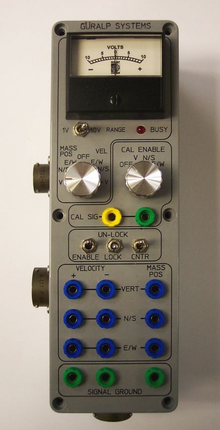
Vertical Borehole Seismometer

         poles/zeros notation.

1.1 System configuration
         The CMG-3 series of seismic instruments share a number of features:

               •   a modular sensor sonde, which can be fitted with a single-jaw or
                   three-jaw holelock mechanism as required,

               •   a pit head installation including a surface control unit, and

               •   a number of additional, optional control units which may be
                   connected to the surface control unit to perform installation and
                   maintenance tasks.

         For example, a borehole or pit installation of a CMG-3V or 3ESPV
         instrument with a three-jaw hole lock has the following layout:

         CMG 3-series instruments are also suitable for installing in boreholes
         with sand backfill. In this case no hole lock unit is necessary.

October 2006                                                                           5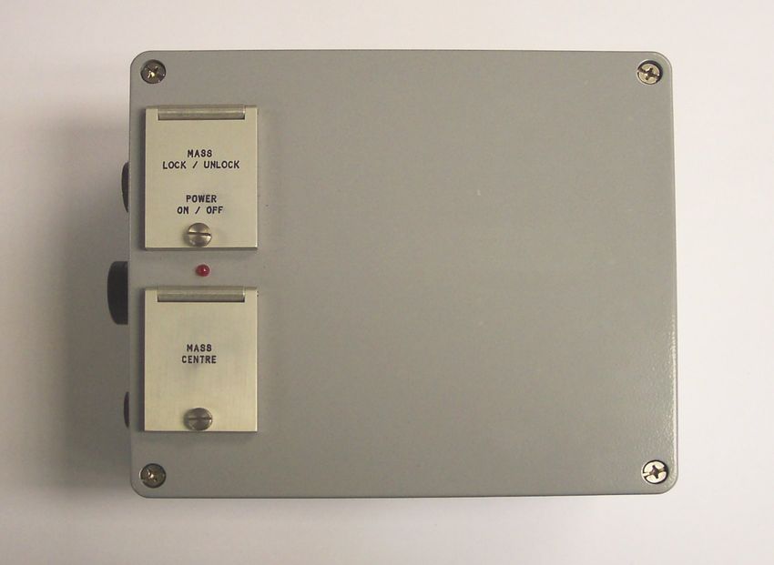
CMG-3V / 3ESPV

        The CMG-3V sensor is identical to the vertical-component module of
        the 3TB instrument, allowing you to build mixed arrays of 3V and 3TB
        sensors with identical response characteristics. Likewise, the CMG-
        3ESPV and 3ESPB instruments use the same vertical component.

1.2 Digital borehole installations
        The Güralp DM24 digitizer is available in a borehole sonde form.
        Connecting a Güralp borehole instrument to a downhole digitizer
        allows you to construct a true digital borehole installation. This has
        several advantages over a traditional borehole setup:

           •   Digital signals are not subject to attenuation as they travel up to
               the surface, so signals received are stronger and more reliable.

           •   Digitizing the data at source allows you to ensure that its origin
               can be reliably traced.

           •   The DM24 digitizer may also be combined with an
               Authentication Module within the borehole sonde, allowing you
               to generate cryptographically-signed data at the point of origin.

        A digital borehole installation can be provided with RS232, RS422 or

6                                                                           Issue B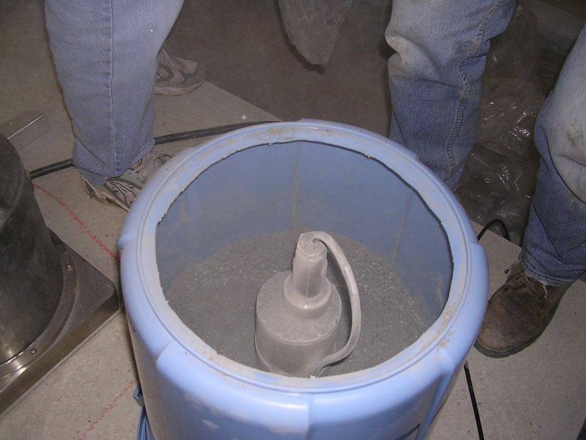
Vertical Borehole Seismometer

         fibre-optic links to the surface, depending on the depth of the
         borehole.

         When a downhole digitizer is present, it takes the place of the strain
         relief unit in the borehole. The surface unit also takes a slightly
         different form, with a serial connector allowing you to attach a modem
         or other communications link. In this type of installation, instead of
         using the surface unit to pass control signals to the sensor, all
         functions can be accessed remotely via the digitizer.

         If you prefer to install a stand-alone digitizer at the surface, it should
         be connected to the 19-pin RECORDER socket of the surface control
         unit.

1.3 The hole lock system
         The hole lock clamp unit in a 3V or 3ESPV instrument provides a
         stable platform for the sensor modules mounted above and below it. It
         is designed to maintain a positive pressure on the borehole casing over
         a prolonged period of time without attention, and to fix the sonde in
         place whilst avoiding transmitting any stresses to the seismic sensors.

         Either single-jaw or three-jaw hole lock units may be provided. Güralp
         Systems hole locks are constructed to order from accurate
         measurements of your borehole at the depth you wish to install the
         instrument.

         In installations with sand backfill, or where the instrument rests on the
         bottom of the borehole, a hole lock may be unnecessary.

         The three-jaw hole lock
         This is the standard option for uniaxial instruments; it can be installed
         in boreholes between 3.5” / 89 mm and 7” / 178 mm in diameter.

         The three-jaw hole lock consists of a set of three active clamp arms
         attached to a compression spring, which forces them to swing out from
         the sonde and wedge themselves against the borehole wall. Serrated
         steel jaws at the end of each arm provides maximum grip against the
         borehole casing. This configuration ensures that the sonde body is
         held parallel to the axis of the borehole and prevented from twisting or
         slipping under the influence of ground vibrations.

October 2006                                                                          7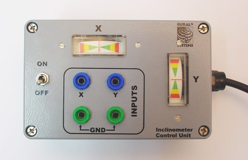
CMG-3V / 3ESPV

        The motor has a power system separate from that of the sensor, and
        can be controlled from the surface using a hole lock control unit. Once
        the sonde is installed, the hole lock control unit may be removed.
        Without power, the hole lock will not be able to retract, and the sensor
        will be secured.

        The single-jaw hole lock
        A single-jaw hole lock is available which is smaller and lighter than
        the three-jaw lock, but does not grip the borehole casing with as much
        force. The single jaw hole lock is the standard option for triaxial
        borehole instruments. It consists of an active clamp arm and a number
        of skids or studs on the sonde body. The arm is attached to a
        compression spring, which forces it to swing out from the sonde and
        wedge the body against the borehole wall. A serrated steel jaw at the
        end of the arm provides maximum grip against the borehole casing.
        The skids or studs and the locking arm together form a multi-point
        clamp, which aligns the sonde body parallel to the axis of the borehole
        and holds it firmly in place so that it cannot twist or slip under the
        influence of ground vibrations.

        The spring inside the lock provides around 60 kg of force at its locking
        position. A DC actuator retracts the arm into the body of the lock so
        that the sensor mechanism can be installed and removed. The actuator
        consists of a 14 W DC motor with a planetary reduction gearhead,
        which drives the nut of a ball lead screw through the helical drive

8                                                                         Issue B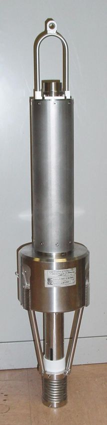
Vertical Borehole Seismometer

         gears. The thread of the lead screw is prevented from turning, and so
         moves linearly when the nut turns.

1.4 Vault conversion base
         As an alternative to borehole installation, the CMG-3V and 3ESPV can
         be supplied with a vault conversion base. This metal piece can be
         attached to the bottom of the sensor module to provide a stable three-
         point contact with a seismic pier.

         The instrument can then be covered with an insulating box or
         backfilled with dry sand as in the photograph below.

         The conversion base can easily be replaced with a hole lock module in
         the event that the instrument is later installed in a borehole.

October 2006                                                                      9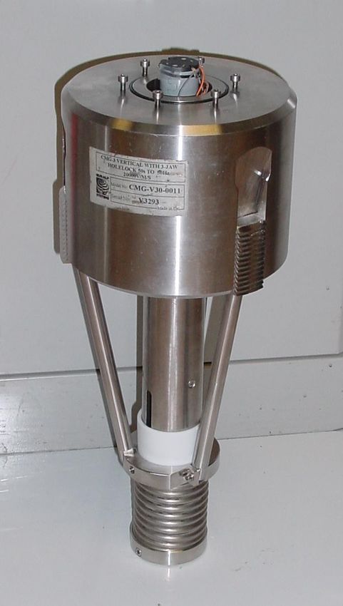
CMG-3V / 3ESPV

2 First encounters

2.1 Unpacking and packing
        The 3V and 3ESPV seismometers are delivered in a single
        transportation case, with the sensor system and hole lock mechanism
        (if ordered) packed separately. The packaging is specifically designed
        for the instrument and should be reused whenever you need to
        transport it. Please note any damage to the packaging when you receive
        the equipment, and unpack on a clean surface. The package should
        contain:

           •   the seismometer;

           •   a cable to join the sensor to the surface control box;

           •   the surface control unit;

           •   the hole lock control unit, if ordered;

           •   a cable strain relief mechanism, if ordered;

           •   a Handheld Control Unit (HCU) for monitoring sensor outputs
               and calibration, if ordered;

           •   an inclinometer monitor box;

           •   a calibration data sheet;

           •   this manual.

2.2 Handling notes
        The 3V and 3ESPV are sensitive instruments, and is easily damaged if
        mishandled. It should not be operated until it has been securely
        installed in a borehole casing. If you are at all unsure about the
        handling or installation of the device, you should contact Güralp
        Systems for assistance.

           •   Do not bump or jolt any part of the sensor when handling or
               unpacking.

           •   Keep the sonde sections vertical wherever possible. Carry them
               by hand and store in a safe rack. Never drag or roll the sonde.

10                                                                       Issue B
Vertical Borehole Seismometer
• Never lay the sonde horizontally whilst the sensors are
unlocked. If the sensor system topples over, you must inform
Güralp Systems.
• Keep all the parts of the sensor system protected and clean so
that they can be joined together securely. Store in the original
packaging if possible.
• Do not kink or walk on the data cable (especially on rough
surfaces such as gravel), nor allow it to bear the weight of the
sensor.
• Do not connect the instrument to power sources except where
instructed.
2.3 Assembling the instrument
The instrument is delivered in separate sections, which need to be
assembled before it can be installed in a borehole. It is recommended
that you perform these steps with the help of at least one other person.
Important: Make sure your environment is clean and dust free before
assembling the unit. Stray fibres or particles cause damage to the
“O”-ring seals between the components and may render the sensor
unusable. Do not remove the protective caps on the ends of each unit
until you are ready.
1. Ensure that the top surface of the hole lock and the base of the
sensor are clean.
2. Carefully lift the sensor, and connect the cable from the hole
lock to the connector on the sensor base.
3. Gently lower the sensor onto the hole lock, making sure that it is
properly aligned and no wires are trapped beneath the base.
4. Using the cap head screw provided, fasten the sensor base onto
the hole lock.
2.4 Control units
The 3V and 3ESPV are operated from the surface through various
control units. All the instrument functions can be accessed through
one or other unit. Most can be removed from the site once the
instrument is ready for use.
October 2006 11CMG-3V / 3ESPV
Some of these control units are optional and may not have been
supplied with your installation. Their functions can be duplicated
either by applying voltages directly to control lines (see appendixes for
pinout information) or through a connected Güralp digitizer such as
the CMG-DM24. The DM24 digitizer is able to pass commands to the
instrument from a Data Communications Module (DCM) or a computer
running Güralp Systems' Scream! software, allowing you to access all
of the instrument's functions remotely.
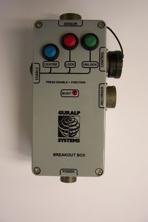
The breakout box
The breakout box is normally placed where the signal cable emerges
from the borehole. It provides connectors for attaching the various
other control units, supplies power to the instrument and relays output
signals to a recorder or digitizer.
• The SENSOR connector is a 32-way mil-spec plug, and should
be connected to the borehole instrument with the cable
provided.
• The RECORDER connector is a 26-way mil-spec plug. This
should be connected to an analogue data recorder or stand-alone
12 Issue BVertical Borehole Seismometer
digitizer. In systems using downhole digitizers, this is replaced
by a 10-way mil-spec serial connector for attaching to a Data
Communications Module (DCM), modem or other
communications link.
• The CONTROL connector is a 26-way mil-spec plug intended
for connecting to an external controller or Handheld Control
Unit, with the same pin out as the RECORDER connector.
• The POWER connector is a 10-way mil-spec plug, which should
be connected to a source of 12 – 30 V DC power, for supplying to
the borehole instrumentation. When operating the hole lock,
you should connect the Holelock Control Unit to this connector.
Because of the high voltages employed, the hole lock circuitry is
entirely isolated from the rest of the electrical systems in the
sensor and surface unit; it is not usual to power the sensor
whilst using the hole lock.
For deep-borehole installations (over 50 m) we recommend that you
use a breakout box with internal line drivers, to ensure that logic
signals are reliably transmitted to the sensor. Contact Güralp Systems
for advice.
Note: The breakout box looks very similar to other Güralp breakout
boxes. However, its internal wiring is different from that used for some
other instruments. For this reason, if you are using several instrument
types, you should mark each breakout box clearly so that it is always
used with the correct instrument.
Surface control units
Most newer 3V and 3ESPV units have state-of-health (SOH) electronics
installed within the sensor housing, which manage the instrument's
mass control functions. In some installations, however, these
electronics are installed at the surface, in a dedicated control unit. This
unit provides the same connectors as the breakout box, but is rather
larger. In addition to the SOH electronics, it contains a differential
input to differential output amplifier, and a fuse to protect the internal
DC–DC converter against polarity reversal. Its connectors are the same
as those on the breakout box, except that
• POWER and HOLELOCK POWER are brought out on separate
10-pin connectors, and
• the SENSOR connector is a 32-pin mil-spec plug, with a
straight-through cable to the sensor.
October 2006 13CMG-3V / 3ESPV
The surface control unit is supplied with a 3 m cable as standard. This
can be extended up to 100 m without compromising signal quality.
The sensor uses amplifiers with high common mode rejection to
ensure the signal to noise ratio is maintained over this distance.
Individually shielded twisted-pair cabling must be used for the sensor
outputs, control lines and power supply. If you need to make up a
suitable cable, you should confirm the cable type with Güralp
Systems.
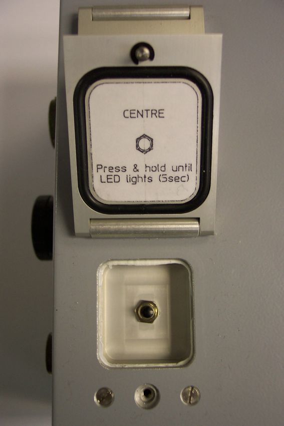
The push-button switches which operate the sensor's control
commands (mass locking, unlocking, and centring) are housed beneath
waterproof lids. You must release the fixing screws holding the lids
down before you can initiate any commands.
14 Issue BVertical Borehole Seismometer
Calibration
To calibrate the instrument, the Calibration enable line must be
activated. This operates a relay which allows a calibration signal to
flow through the transducer feedback coil. This provides an extra force
acting on the sensor masses, producing a corresponding deflection in
the output signal, which can be analysed by a control computer to
extract the seismometer's response characteristics.
Most Güralp instruments are manufactured with active-low
Calibration enable lines. However, instruments with active-high
calibration can be manufactured on request.
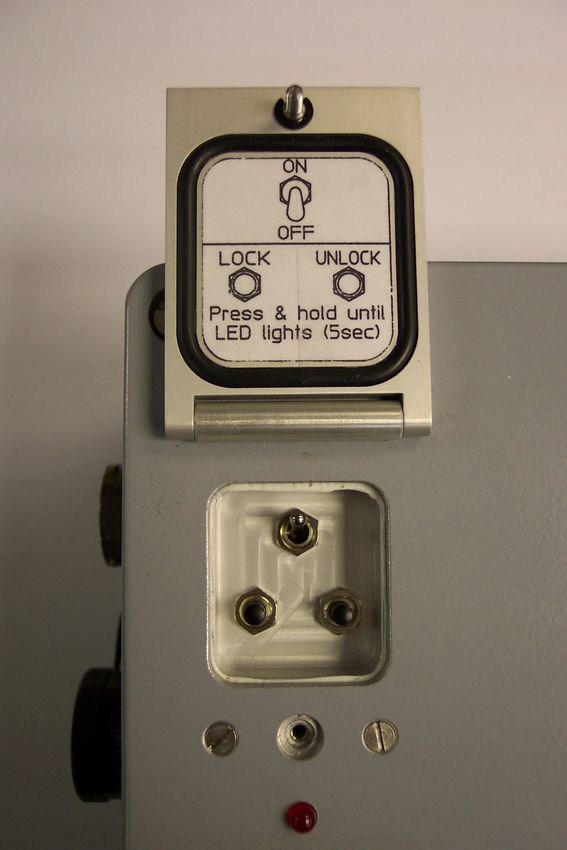
Mass locking and unlocking
The instrument is delivered with its sensor mass locked, so that they
will not be damaged in transit. You should lock the mass whenever
you need to move the instrument.
To unlock the instrument, hold down the ENABLE and UNLOCK
buttons (or the UNLOCK switch on a surface control unit) for at least
six seconds. The sensor's microcontroller will free the mass and ready
it for use. Once this is done, the controller automatically starts a
centring cycle. If you issue an UNLOCK command when the mass is
already free, the instrument will attempt to lock the mass first, and
then unlock it in sequence as normal.
To lock the instrument, hold down the ENABLE and LOCK buttons (or
October 2006 15CMG-3V / 3ESPV
the LOCK switch) for at least six seconds. The sensor's microcontroller
will lock the vertical sensor mass. The instrument is now protected
against accelerations up to 10g, and is ready for transportation.
Centring
To centre the instrument, hold down ENABLE and CENTRE buttons
(or the CENTRE switch) for at least six seconds. If the masses are
locked, the microcontroller will do nothing. Otherwise, it attempts to
zero the output of the sensor. Inside, a motor-driven adjuster presses a
small spring lever against the boom until the mass position output
indicates an offset close to zero.
After successful centring, the mass position outputs should be in the
range 0.1 – 0.8 V. If the centring process leaves the mass position
outputs above ±1.1 V, start another centring cycle. You will probably
need to perform several rounds of centring before the masses are ready.
The handheld control unit
This portable control unit provides easy access to the seismometer's
control commands, as well as displaying the output velocity and mass
position (i.e. acceleration) on an analogue meter.
16 Issue BVertical Borehole Seismometer
Connections
The HCU provides
• two identical 26-pin connectors for attaching to the HCU or
RECORDER connectors of the Surface Control Unit, and
• a 10-pin connector through which you can power the
instrument, if desired. The power pins on this connector are
directly connected to those on the SENSOR POWER connector
of the Surface Control Unit. When using this alternative power
connection, you should ensure you do not inadvertently connect
two power supplies together.
Signal meter
The upper section of the HCU contains a simple voltmeter for
monitoring various signals from the instrument.
• To monitor the velocity output, switch the dial to V VEL.
• To monitor the mass position output, switch the dial to V MASS
POS.
• You can set the range of the meter with the RANGE switch.
When switched to 10 V, the meter ranges from –10 to +10 V (as
marked.) When switched to 1 V, the range is –1 to +1 V.
Calibration and control
You can calibrate a 3V or 3ESPV sensor through the HCU by
connecting a signal generator across the yellow and green
CALIBRATION SIGNAL inputs and turning the CAL ENABLE dial to
V. The sensor's response can now be monitored or recorded, and
calibration calculations carried out.
The section of the HCU below the calibration lines controls the
instrument's mass control system. To initiate locking, unlocking, or
centring, hold down the ENABLE switch on the HCU together with the
appropriate switch for the command you want to issue for at least six
seconds.
Banana sockets
The remainder of the HCU provides useful connections for each of the
signal lines from the instrument, for attaching to your own equipment
as necessary.
October 2006 17CMG-3V / 3ESPV
The inclinometer monitor unit
The borehole sensor system can operate successfully in boreholes with
a tilt angle up to 3.5 °. To check that the instrument is installed
suitably close to the vertical, a two-axis inclinometer is installed
within the sensor housing. The inclinometer monitor unit is used as a
visual guide to the sensor's tilt only, and should not be used if precise
attitude information is required. You should check the inclination of
the instrument before unlocking the sensor masses, since too great a
tilt can damage the components.
To measure the attitude of a 3V or 3ESPV instrument:
1. Connect the inclinometer monitor unit to the CONTROL
connector of the surface control unit.
2. Switch the ON/OFF switch on the monitor unit to the ON
position. The inclinometer is powered separately from other
parts of the system; this switch provides power to the downhole
circuitry as well as to the monitor unit. The inclinometer should
not normally be powered up whilst the sensor is in use.
3. Read off the X and Y components of the tilt from the analogue
meters.
4. If both tilts are within the green shaded region, the instrument is
close enough to vertical that it can be levelled and centred
successfully. If either output is in the red shaded region, you
should not attempt to unlock or centre the sensor masses.
Instead, if possible, you should move the instrument within the
borehole to a place where it can lie closer to vertical.
If you need to use the outputs of the inclinometer for some other
18 Issue BVertical Borehole Seismometer
purpose, you can also connect a multimeter to the banana sockets on
the inclinometer monitor unit.
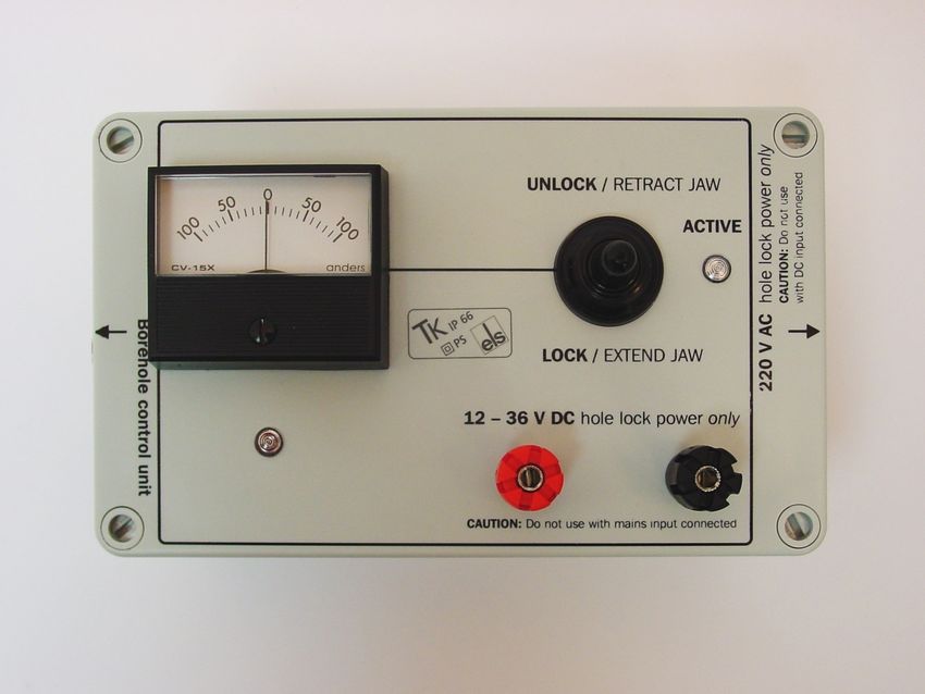
2.5 Operating the hole lock
The hole lock, if fitted, can be extended and retracted using the hole
lock control unit:
Caution: The hole lock may be using high-voltage mains (outlet)
power.
1. Connect the hole lock control unit to the HOLELOCK POWER
connector of the surface control unit, and to a mains power
supply. Alternatively, connect a 12 – 24 V DC power supply
across the input terminals of the hole lock control unit. Do not
connect both DC and mains power at the same time.
The hole lock control unit supplied in regions with 220 V AC
mains power differs from that supplied for 110 V AC mains
power. You should ensure that you provide the correct voltage
to the hole lock control unit, otherwise damage may result to the
sensor.
2. If you are supplying power to the sensor through another
connector, ensure that it is switched off whilst you operate the
hole lock.
3. If you are using a deep-borehole hole lock control unit, set the
dial to zero.
October 2006 19CMG-3V / 3ESPV
Engaging the hole lock
To extend the jaw of the hole lock:
1. Hold the switch on the hole lock control unit in the EXTEND
JAW or + position. If you are using a deep-borehole control
unit, there will be an additional dial compared to the unit
pictured; turn this until the built-in ammeter reads around 0.1
A.
2. When the arm makes contact with the borehole casing, the
current will drop slightly. Continue holding the switch in the
EXTEND JAW position.
3. When the lock arm reaches its fully extended position, the
motor will automatically stop and the current will drop to 0 A. If
using a deep-borehole unit, return the dial to zero.
4. If the current has not dropped quite to zero after 30 – 40 s of
operation, release the switch, wait a few seconds, and push it
back to the EXTEND JAW position briefly. If the arm is not
completely extended, you will see a surge of current. If the
current remains constant, the jaw is at its maximum reach.
5. Once the sensor is locked in place, it is recommended that you
remove the hole lock power cable and control unit from the site.
Without power, the hole lock will not be able to retract, and the
sensor will be secure.
20 Issue BVertical Borehole Seismometer
Disengaging the hole lock
To retract the jaw of the hole lock:
1. Tension the load bearing cable, to take up any slack.
2. Hold the switch on the hole lock control unit in the RETRACT
JAW or – position. If using a deep-borehole control unit, also
turn the dial until the built-in ammeter indicates 0.3 – 0.5 A.
More current is drawn retracting the arm, because the motor is
now working against the spring.
3. When the lock arm reaches its fully retracted position, the
motors will automatically stop and the current will drop to 0 A.
If using a deep-borehole unit, return the dial to zero.
Manual operation
If you prefer, you can operate the hole lock by applying voltages
directly to the sensor.
• To extend the jaw, connect the Hole Lock Motor pin on the
sensor (or on the Surface Control Unit's HCU or RECORDER
connectors) to a +12 V power source, and the Hole Lock Motor
Return pin to 0 V.
• To retract the jaw, reverse the polarity so that the Hole Lock
Motor Return pin is at +12 V and the Hole Lock Motor pin is at
0 V.
October 2006 21CMG-3V / 3ESPV
3 Installing in a borehole
Before installing any instrument in a borehole, it is recommended that
you prepare the installation site so there is clear access all around the
hole.
• Keep the borehole capped at all times except when inserting or
removing the instrument, so that debris and tools do not
accidentally fall in.
• Lay out the cables beside the borehole, or set up a cable drum
nearby, so that they do not become tangled.
• Ensure the tripod is tall enough to hang the entire installation
(sensor and strain relief unit or digitizer) from it, with the sensor
off the ground.
• Use a winch with a depth gauge if possible, or measure out the
cable beforehand.
Most installations are equipped with a strain relief unit, which
consists of a metal arm that swings out from the load-bearing cable to
wedge against the side of the borehole. This removes any strain in the
load-bearing cable and prevents vibrations from the surface from being
transmitted to the instrument. In installations with a downhole
digitizer, the strain relief arm is fitted to the base of the digitizer sonde;
the phrase “strain relief unit” in the following instructions should be
taken to refer to the digitizer's strain relief arm.
3.1 Installing a sensor with hole lock unit
1. Connect the signal cable to the connector on top of the sensor.
Ensure that the “O”-rings inside the housing are clean, and
tighten the knurled connector nut to its end stop.
22 Issue BVertical Borehole Seismometer
2. If applicable, you should test the hole lock mechanism before
installing the sensor. For safety reasons, the hole lock is
normally supplied with the arm extended.
To test the mechanism, connect the signal cable to a surface
Control Unit and Holelock Control Unit, and attempt to retract
the hole lock arm (see Section 2.5, page 19.) If this fails, you
should contact Güralp Systems. Extend the arm once more.
3. Fix the main lifting cable to the shackle on top of the strain
relief mechanism, and run the signal cable through the
mechanism using the built-in clamps (without tightening them.)
Do not allow the signal cable to bear any of the sensor's weight.
October 2006 23CMG-3V / 3ESPV
4. Attach the lifting loop to the sensor using four M5×16 screws
(provided).
5. Join the loop to the bottom of the strain relief mechanism using
the linking cable provided.
6. Using a small winch, hoist up the sensor package and strain
relief mechanism until both are hanging by the lifting cable,
with the strain relief mechanism extended. Tighten the cable
clamps on the strain relief unit, allowing a little slack in the
signal cable.
24 Issue BVertical Borehole Seismometer
7. Fix the signal cable to the main lifting cable about 1 m above the
strain relief mechanism using a metal clamp (a nylon cable tie
may be sufficient for shallow installations.) Leave a little slack
in the signal cable between the clamp and the strain relief
mechanism.
8. Position the assembly over the top of the borehole. Do not allow
it to drag across the ground.
9. Lower the sonde so that its base is just level with the borehole
mouth. If there is a depth gauge on the winch, set this to zero.
10.Continue to lower the sonde to a depth of about 1 m, so that the
instrument is still visible.
11.Extend the hole lock arm (see Section 2.5, page 19) to check
that it fits your borehole. The current drawn should dip slightly
as the arm touches the casing, then drop to zero when it is fully
extended. Check that the sonde is firmly anchored to the
borehole casing by attempting to slacken the load bearing cable.
If it remains taut, the sonde is still loose within the borehole. Do
not proceed with installation in this case. Instead, you should
either move the instrument to a narrower section of the borehole
and try again, or contact Güralp Systems to fit a longer hole
lock, quoting accurate measurements of your borehole.
12.Power up the instrument from a suitable power supply.
13.Level and centre the sensor (see Section 3.5, page 39) so that it
can be tested.
October 2006 25CMG-3V / 3ESPV
14.Check that the sensor is functioning correctly by connecting a
meter or monitoring device to the sensor outputs. If the sensor
fails to register ground movements, contact Güralp Systems.
15.Lock the sensor masses once more, tension the load bearing
cable and retract the hole lock arm.
16.Gently lower the sensor to the required depth. At approximately
20 m intervals, fix the signal cable to the load bearing cable
using metal clamps (nylon cable ties every 5 m may be sufficient
for shallow installations). This will ensure that the signal cable
does not become kinked or trapped within the borehole. Leave a
little slack on the signal cable each time, so that it does not bear
any weight. Too much slack, however, will cause the cable to
scrape against the borehole casing.
17.Fix the sensor system into the borehole using the hole lock arm
(see Section 2.5, page 19.)
If you are installing the sensor in a deep borehole, the weight of
the sensor will stretch the load bearing cable slightly.
Remember to allow for this when raising or lowering the cable
in the following steps.
18.Use the winch to drag the assembly up within the borehole for a
distance of 15 – 30 cm. This will ensure that the hole lock arm
and the skids or studs on the sonde keep the sensor package
vertical within the borehole. Do not drag too far, or you will
damage the contact points.
19.Lower the load bearing cable by around 30 cm to engage the
strain relief unit inside the borehole casing, and to provide some
slack in the cables.
20.Clamp the load bearing cable to the top of the borehole.
21.Tie the lifting and signal cables together above the strain relief
mechanism using tie wraps.
22.The sensor can now be levelled and unlocked ready for use.
26 Issue BVertical Borehole Seismometer
3.2 Installing a sensor using sand backfill
Dry sand backfill is a convenient and effective way of installing a
borehole or posthole sensor in a time-stable environment. The
presence of sand not only fixes the sensor in place at the bottom of the
hole, but also reduces noise due to air convection.
The ideal type of sand to use is the fine, kiln-dried sand used for
children's play sandpits. This is readily available in airtight bags, is
thoroughly washed and clean, and will contain little sediment. (When
dried out after wetting, sand containing foreign matter may solidify
and “concrete” the sensor in position.) This sand is suitable for use in
both dry and damp boreholes.
In the procedure outlined below, the sensor rests on a pad of sand
around 300mm thick. This pad will absorb any residual moisture at
the bottom of the borehole, and ensure that the surroundings of the
instrument are kept dry.
After positioning the sensor, more sand is added to fill the space
between it and the borehole casing, holding it firmly in place. The
sand should reach within 30mm of the top of the instrument, but
should not cover it. This way, the instrument can be more easily
recovered when it requires maintenance or replacement. This is
particularly important if the borehole is not completely dry, since
moist sand does not flow well.
The following photographs show the steps involved in backfilling with
sand:
October 2006 27CMG-3V / 3ESPV
Procedure
To install a sensor at the bottom of a borehole of known depth using
sand backfilling:
1. Measure or calculate the physical volume of the unit which is to
be installed in the borehole. (The volume of a cylinder v =
πr2h.) Also measure the internal diameter of the borehole.
2. Measure and pour in a sufficient quantity of sand to fill the
borehole to a depth of around 300mm.
3. Connect the signal cable to the connector on top of the sensor.
Ensure that the “O”-rings inside the housing are clean, and
tighten the knurled connector nut to its end stop.
4. Fix the main lifting cable to the shackle on top of the strain
relief mechanism, and run the signal cable through the
mechanism using the built-in clamps (without tightening them.)
Do not allow the signal cable to bear any of the sensor's weight.
28 Issue BVertical Borehole Seismometer
5. Attach the lifting loop to the sensor using four M5×16 screws
(provided).
6. Join the loop to the bottom of the strain relief mechanism using
the linking cable provided.
7. Hoist up the sensor package and strain relief mechanism until
both are hanging by the lifting cable, with the strain relief
mechanism extended. Tighten the cable clamps on the strain
relief unit, allowing a little slack in the signal cable.
8. Fix the signal cable to the main lifting cable about 1 m above the
strain relief mechanism using a metal clamp (a nylon cable tie
October 2006 29CMG-3V / 3ESPV
may be sufficient for shallow installations.) Leave a little slack
in the signal cable between the clamp and the strain relief
mechanism.
9. Position the assembly over the top of the borehole. Do not allow
it to drag across the ground.
10.Lower the sensor so that its base is level with the borehole
mouth. Set the depth gauge on the winch to zero.
11.Calculate how much lifting cable must be lowered into the
borehole, taking into account the length of the sensor and the
strain relief assembly or digitizer.
12.Begin lowering the sensor down the borehole, keeping track of
the depth reached.
13.At approximately 20 m intervals, fix the signal cable to the load
bearing cable using metal clamps (nylon cable ties every 5 m
may be sufficient for shallow installations). This will ensure
that the signal cable does not become kinked or trapped within
the borehole. Leave a little slack on the signal cable each time,
so that it does not bear any weight. Too much slack, however,
will cause the cable to scrape against the borehole casing.
14.Whilst monitoring the depth of the sensor, carefully approach
the sand layer at the bottom of the borehole. The lifting cable
will go slack when the sensor makes contact with the sand.
If the lifting cable goes slack before the sensor has reached the
sand layer, it may have become caught on a bad joint or lip in
the borehole; carefully raise and lower the instrument to free it.
15.When you have reached the bottom, use the winch to lift the
package slightly, taking the slack off the cable. This ensures that
the sensor is hanging vertically within the borehole, and is no
longer in contact with the sand bed.
At this point, you may wish to use an inclinometer monitor unit
to check that the instrument is sufficiently close to vertical to be
properly centred. See Section 2.4, page 18, for details.
30 Issue BVertical Borehole Seismometer
16.Calculate the volume of dry sand required to fill the gap
between the sensor and the borehole liner to the level of the top
of the sensor (v = πr2h using the internal radius of the borehole,
less the volume of the instrument determined in step 1.)
17.Pour this sand into the borehole. If you can, check how much of
the sensor is covered with sand. Do not overfill the hole.
18.Carefully slacken the load bearing cable. This will engage the
locking arm of the strain relief mechanism and secure the
installation within the borehole.
19.Without pulling or lifting the sensor, lightly shake the cables to
remove any sand that may have fallen onto them or onto the
strain relief mechanism.
20.Clamp the load bearing cable to the top of the borehole, and
remove the winch.
21.The sensor can now be centred and unlocked (see Section 3.5,
page 39)
3.3 Assembling the winch
If required, Güralp Systems can provide a winch suitable for installing
a borehole sensor. The winch and tripod are supplied as a set of parts
which you can assemble on site:
There are two sections for each leg of the tripod. The upper sections
are pre-attached to the head of the tripod; the lower sections are
supplied detached.
1. Slide the lower sections all the way into the head with the
retaining tape loops facing outwards.
October 2006 31CMG-3V / 3ESPV
2. If you are working on a surface of sand or soil, rotate the feet so
that the points face downwards (left). For rock or other hard
surfaces, ensure the pads face downwards (right).
3. Erect the tripod above the borehole, and run the yellow
retaining tape through the loops. Fasten together the ends of the
tape.
32 Issue BVertical Borehole Seismometer
4. The lifting cable is supplied with a loop at one end. Run this
over one of the pulleys at the top of the tripod, so that the loop
hangs down between the legs. If the loop is not provided, you
can make one by untwisting three outer strands from the (7-
core) cable, crossing the two sets, and pleating the three outside
strands back around the remaining four in the opposite
direction. Secure the loop with a cable clamp.
5. Run the sensor signal cable through the other pulley. Secure
both cables in their pulleys by sliding the attached bolts into
place.
6. Extend each of the three legs in turn to the height you require,
finishing at the leg with the winch attached.
October 2006 33CMG-3V / 3ESPV
7. Take the end of the load-bearing cable without the loop, and
screw it to the axle inside the winch using a 4 mm Allen key
(provided) as shown.
8. Attach the handle to the side of the winch opposite the ratchet
mechanism, and fasten it in place with a collar, washer and
screw, using the larger Allen key.
34 Issue BVertical Borehole Seismometer
9. Wind the cable onto the winch by rotating the handle. Ensure
that the cable builds up neatly across the drum. Continue
winding until the loop on the other end is as high as you need it
to install the equipment.
If the ratchet prevents you from winding the cable on, twist the
metal boss in the DOWN direction to free the cable.
10.Remove the handle, and screw it onto the metal spool of the
ratchet mechanism.
October 2006 35CMG-3V / 3ESPV
11.Hang the strain relief unit and instrument(s) from the loop at
the other end of the cable. You are now ready to lower the
assembly into the borehole as described above.
3.4 Earthing a borehole sensor
To achieve the best performance from any borehole instrument, you
must make sure that the sensor electronics, its casing and the power
supply share a common, local ground, and that all power and data
lines are adequately protected against lightning and other transients.
This section describes techniques for grounding sensor equipment
which have proved effective in many installations. However, local
conditions are always paramount, and you should design your
installation with these in mind. Any regulations in force at your
chosen location must also be followed.
Installations with AC power supplies
If you are using mains (outlet) power, or some other AC power
distribution system, we recommend installing a fully isolating
transformer between it and the power supply for the instrument. This
will allow full control of the local grround.
A spark-gap surge protector should also be installed on the mains side
of the transformer, so that transient overvoltages are not transmitted
across it. Suitable protectors are available off the shelf from several
suppliers. On the sensor side, surge protection is installed as standard
within all new Güralp borehole sensors and control equipment. If your
surface installation includes third party electronics, digitizers, etc., you
may need to install additional protection where power and data lines
enter the surface enclosure. Contact Güralp Systems if you are unsure.
36 Issue BVertical Borehole Seismometer
Within the installation, a single ground point should be established,
which is connected to a local ground plate. All earth lines for
equipment in the installation, such as the casings of the transformers
and of the sensor electronics, as well as the signal ground line from the
sensor, should be connected to this plate.
The best local earth point in many installations is the borehole itself.
For this to work, the borehole must have a conductive casing and be
situated close (CMG-3V / 3ESPV
For boreholes with a metallic casing at the bottom and plastic above,
we recommend connecting a cable between the sensor housing and the
ground plate so that the lower borehole casing acts as the earthing
point. Again, the
If there is a significant distance (>30 m) between the borehole and the
surface installation, the resistance of the earth cable may make it
impractical to use the borehole as an earthing point. In these cases,
you will have to connect the local ground plate to an earth stake near
to the enclosure; any coupling between this sensor-local earth line and
ground lines for other parts of the system must be minimized.
Installations with DC power supplies
Güralp sensors require a 24 V DC power supply. In most cases, this is
provided by an isolating DC/DC converter installed at the surface. This
converter can be earthed to the local ground plate as above.
However, DC/DC converters contain sensitive electronics, which must
be protected thoroughly. We recommend installing a full surge
protection unit in addition to the spark gap protector. This protection
is installed on the supply side of the isolator, so it must be earthed
separately from the borehole installation. Otherwise, transients in the
power supply will couple to the sensor.
As with AC installations, if the borehole is more than around 30 m
from the surface enclosure, you will need to provide a second earthing
point for the local ground plate.
DC power is most commonly available at self-contained installations
with power supplied from batteries, solar panels, or a wind generator.
In these cases, the power supply may already have protection from
transients installed, in which case you may not need such
comprehensive protection (although some form of protection is always
necessary.)
External lightning protection
The surface installation building, and if possible the borehole also,
should be protected by lightning conductors. These should lead to
ground well away from the borehole. As a rule of thumb, a lightning
mast provides a “zone of protection” within a 45 ° cone the height of
the mast.
If you are using two earthing points, for example in the DC installation
shown above, it may be convenient to connect the lightning conductor
to the supply-side earthing point. In any case, the lightning earth must
38 Issue BVertical Borehole Seismometer
be well separated from the borehole (and its earth, if it needs one.)
3.5 Levelling and centring
Once it is installed, you should level and centre the instrument ready
for use. This can be done using the various surface control units.
The 3V and 3ESPV instruments are less susceptible to tilt than
instruments with horizontal components. However, to get the best
performance you should still make sure the instrument is as close to
vertical as possible.
1. Connect an inclinometer monitor unit to the borehole control
unit.
2. Turn on the borehole control unit using the ON/OFF switch
under the transparent flap.
3. Turn on the inclinometer monitor unit using its ON/OFF switch,
and read off the X and Y components of the tilt from the
analogue meters.
4. If both tilts are within the green shaded region, the instrument is
close enough to vertical that it can be levelled and centred
successfully. If either output is in the red shaded region, move
the instrument within the borehole to a place where it can lie
closer to vertical.
5. Connect a handheld control unit (HCU) to the sensor control
unit, if you have one.
6. Unlock the sensor masses, either by pushing the UNLOCK
buttons of the borehole control unit, or by holding down the
ENABLE and UNLOCK switches of the HCU together for at least
six seconds.
7. When you press the switches, the BUSY LED will come on.
After a while, the unlocking process will be completed, and the
instrument will start centring itself. Whilst this happens, the
BUSY LED will flash.
8. Monitor the mass position output, either using the HCU or your
recording system. The microcontroller inside the unit will zero
the output from the sensor. After successful centring, the mass
position output should be in the range 0.1 – 0.8 V.
October 2006 39CMG-3V / 3ESPV
9. If the centring process leaves the mass position output above
±1.1 V, repeat steps 4 and 5. You will probably need to initiate
the centring process several times before the mass is adequately
centred.
40 Issue BVertical Borehole Seismometer
4 Calibrating the 3V / 3ESPV
4.1 The calibration pack
All Güralp sensors are fully calibrated before they leave the factory.
Both absolute and relative calibration calculations are carried out. The
results are given in the calibration pack supplied with each
instrument:
Works Order : The Güralp factory order number including the
instrument, used internally to file details of the sensor's manufacture.
Serial Number : The serial number of the instrument
Date : The date the instrument was tested at the factory.
Tested By : The name of the testing engineer.
There follows a table showing important calibration information for
the sensor:
Velocity Output (Differential) : The sensitivity of each component to
velocity at 1 Hz, in volts per m/s. Because the 3V uses balanced
differential outputs, the signal strength as measured between the +ve
and –ve lines will be twice the true sensitivity of the instrument. To
remind you of this, the sensitivities are given as 2 × (single-ended
sensitivity) in each case.
Mass Position Output : The sensitivity of the mass position outputs to
acceleration, in volts per m/s². These outputs are single-ended and
referenced to signal ground.
Feedback Coil Constant : A constant describing the characteristics of
the feedback system. You will need this constant, given in amperes per
m/s², if you want to perform your own calibration calculations (see
below.)
Power Consumption : The average power consumption of the sensor
during testing, given in amperes and assuming a 12 V supply.
Calibration Resistor : The value of the resistor in the calibration
circuit. You will need this value if you want to perform your own
calibration calculations (see below.)
October 2006 41CMG-3V / 3ESPV
Poles and zeroes
Most users of seismometers find it convenient to consider the sensor as
a “black box”, which produces an output signal V from a measured
input x. So long as the relationship between V and x is known, the
details of the internal mechanics and electronics can be disregarded.
This relationship, given in terms of the Laplace variable s, takes the
form
( V / x ) (s ) = G × A × H (s )
In this equation
• G is the acceleration output sensitivity (gain constant) of the
instrument. This relates the actual output to the desired input
over the flat portion of the frequency response.
• A is a constant which is evaluated so that A × H (s) is
dimensionless and has a value of 1 over the flat portion of the
frequency response. In practice, it is possible to design a system
transfer function with a very wide-range flat frequency
response.
The normalising constant A is calculated at a normalising
frequency value fm = 1 Hz, with s = j fm, where j = √–1.
• H (s) is the transfer function of the sensor, which can be
expressed in factored form:
In this equation zn are the roots of the numerator polynomial,
giving the zeros of the transfer function, and pm are the roots of
the denominator polynomial giving the poles of the transfer
function.
In the calibration pack, G is the sensitivity given for each component
on the first page, whilst the roots zn and pm, together with the
normalising factor A, are given in the Poles and Zeros table. The poles
and zeros given are measured directly at Güralp Systems' factory using
a spectrum analyser. Transfer functions for the vertical and horizontal
sensors may be provided separately.
42 Issue BVertical Borehole Seismometer
Frequency response curves
The frequency response of each component of the instrument is
described in the normalised amplitude and phase plots provided. The
response is measured at low and high frequencies in two separate
experiments. Each plot marks the low-frequency and high-frequency
cutoff values (also known as –3 dB or half-power points).
If you want to repeat the calibration to obtain more precise values at a
frequency of interest, or to check that a sensor is still functioning
correctly, you can inject calibration signals into the system using a
Güralp digitizer or your own signal generator, and record the
instrument's response.
Obtaining copies of the calibration pack
Our servers keep copies of all calibration data that we send out. In the
event that the calibration information becomes separated from the
instrument, you can obtain all the information using our free e-mail
service. Simply e-mail caldoc@guralp.com with the serial number
of the instrument in the subject line, e.g.
From: your@email.net
To: caldoc@guralp.com
Subject: T3A15
The server will reply with the calibration documentation in Word
format. The body of your e-mail will be ignored.
October 2006 43CMG-3V / 3ESPV
4.2 Calibration methods
Velocity sensors such as the 3V and 3ESPV are not sensitive to
constant DC levels, either as a result of their design or because of an
interposed high-pass filter. Instead, three common calibration
techniques are used.
• Injecting a step current allows the system response to be
determined in the time domain. The amplitude and phase
response can then be calculated using a Fourier transform.
Because the input signal has predominantly low-frequency
components, this method generally gives poor results. However,
it is simple enough to be performed daily.
• Injecting a sinusoidal current of known amplitude and
frequency allows the system response to be determined at a spot
frequency. However, before the calibration measurement can be
made the system must be allowed to reach a steady state; for low
frequencies, this may take a long time. In addition, several
measurements must be made to determine the response over the
full frequency spectrum.
• Injecting white noise into the calibration coil gives the response
of the whole system, which can be measured using a spectrum
analyser.
You can perform calibration either using a Güralp DM24 digitizer,
which can generate step and sinusoidal calibration signals, or by
feeding your own signals into the instrument through a handheld
control unit.
Before you can calibrate the instrument, its calibration relays need to
be activated by pulling low the CAL ENABLE line on the instrument's
connector for the component you wish to calibrate. Once enabled, a
calibration signal provided across the CAL SIGNAL and SIGNAL
GROUND lines will be routed through the feedback system. You can
then measure the signal's equivalent velocity on the sensor's output
line. Güralp Handheld Control Units provide a switch for activating
the CAL ENABLE line.
4.3 Calibration with Scream!
Güralp digitizers provide calibration signal generators to help you set
up your sensors. Calibration is most easily done through a PC running
Güralp's Scream! software.
44 Issue BVertical Borehole Seismometer
Depending on the digitizer type, sine-wave, step and broadband noise
signal generators may be available. In this section, broadband noise
calibration will be used to determine the complete sensor response in
one action. Please refer to the digitizer's manual for information on
other calibration methods.
1. In Scream!'s main window, right-click on the digitizer's icon and
select Control.... Open the Calibration pane.
2. Select the calibration channel corresponding to the instrument,
and choose Broadband Noise. Select the Z component and a
suitable duration and amplitude, and click Inject now. A new
data stream, ending Cn (n = 0 – 7) or MB, should appear in
Scream!'s main window containing the returned calibration
signal.
3. Open a Waveview window on the calibration signal and the
returned streams by selecting them and double-clicking. The
streams should display the calibration signal combined with the
October 2006 45CMG-3V / 3ESPV
sensors' own measurements. If you cannot see the calibration
signal, zoom into the Waveview using the scaling icons at the
top left of the window or the cursor keys.
Drag the calibration stream Cn across the Waveview window, so
that it is at the top.
4. If the returning signal is saturated, retry using a calibration
signal with lower amplitude, until the entire curve is visible in
the Waveview window.
5. If you need to scale one, but not another, of the traces, right-
click on the trace and select Scale.... You can then type in a
suitable scale factor for that trace.
6. Pause the Waveview window by clicking on the icon.
7. Hold down SHIFT and drag across the window to select the
calibration signal and the returning component(s). Release the
mouse button, keeping SHIFT held down. A menu will pop up.
Choose Broadband Noise Calibration.
8.
9. The script will ask you to fill in sensor calibration parameters.
Most data can be found on the calibration sheet for your sensor.
Under Instrument response, you should fill in the sensor
response code for your sensor, according to the table below.
Instrument Type should be set to the model number of the
sensor.
If the file calvals.txt exists in the same directory as
Scream!'s executable (scream.exe), Scream! will look there for
suitable calibration values. See the Scream! manual for details.
46 Issue BYou can also read