Need For Speed GT System Documentation 040-1201-01 Rev. C
←
→
Page content transcription
If your browser does not render page correctly, please read the page content below
Need For Speed™ GT

                                            System Documentation
                                             040-1201-01 Rev. C

                                          ¾ Read this manual before use.
                                          ¾ Keep this manual with the machine at all times.

                                                                   www.globalvr.com
                                                                   service.globalvr.com
                                                                   techsupport@globalvr.com
                                                                   408-597-3400

© 2004 Electronic Arts Inc. Need for Speed, EA GAMES, the EA GAMES logo and Electronic Arts are trademarks or registered trademarks of Electronic Arts
Inc. in the U.S. and/or other countries. All rights reserved. EA GAMES™ is an Electronic Arts™ brand. The trademarks Lamborghini, Diablo 6.0 VT,
Murciélago and all associated logos are used under license of Lamborghini ArtiMarca S.p.A., Italy. Aston Martin V12 Vanquish used under license from
Aston Martin Lagonda Limited, Ford Motor Company. The BMW logo, wordmark and model designations are trademarks of BMW AG and are used under
license. Dodge is a registered trademark of DaimlerChrysler Corporation. The Dodge® Viper GTS model and its trade dress is used under license from
DaimlerChrysler. © DaimlerChrysler Corporation 2004. Ford nameplates are registered trademarks owned and licensed by Ford Motor Company. General
Motors Trademarks are used under license to Electronic Arts Inc. The word "Jaguar", the leaping cat device and the characters "XKR" are trademarks of
JAGUAR CARS LTD, ENGLAND and are used under license. Elise, Lotus and Lotus Round Device are registered trade marks of Group Lotus plc. "Mercedes",
"Mercedes Benz", "CL" and "CLK" are trademarks of DaimlerChrysler. Licensed from Dr. Ing. h.c. F. Porsche AG under certain Patents. Porsche, 911, and
Carrera are registered trademarks of Dr. Ing. h.c. F. Porsche AG. McLaren, McLaren Cars Ltd., McLaren F1, McLaren F1LM are trademarks of McLaren Cars
Ltd. Global VR and the Global VR logo are trademarks of Global VR, Inc. All other trademarks are the property of their respective owners. U.S. Patent Nos.
5,269,687; 5,354,202; and 5,577,913 used under license from Midway Games West Inc.

GLOBAL VR IS AN AUTHORIZED ELECTRONIC ARTS DISTRIBUTOR.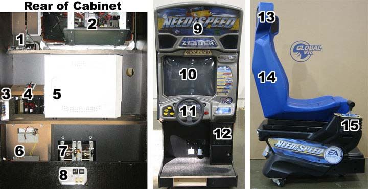
TABLE OF CONTENTS

Table of Contents

    Table of Contents .......................................... 2          Game Stats ..................................................27
                                                                            Controls Menu ..............................................28
    Chapter 1 ---- Introduction ................................ 3
                                                                            Monitor Calibration Test..................................29
    Safety ............................................................ 3
      Warnings .................................................... 3       Sound Test ...................................................30
      Environmental Conditions ............................... 3            Chapter 5 ---- Playing a Game ..........................31
    Regulatory Notices .......................................... 4         Starting a Game ............................................31
      FCC Notices (United States) ........................... 4
                                                                            Playing a Game .............................................33
    Need For Speed™ Description ........................... 5
     Need For Speed™ GT Upgrade ....................... 5                   Chapter 6 ---- Service .....................................34
     Cabinet Models ............................................ 6          Cabinet Specifications.....................................34
                                                                              Hardware Features .....................................34
    Chapter 2 ---- Installing a New Cabinet ............... 7
                                                                            Troubleshooting .............................................35
    Basic Cabinet Setup (All Models) ........................ 7
                                                                              Video Troubleshooting..................................35
    Standard Cabinet Installation ............................. 8             Audio Troubleshooting..................................36
      Standard Cabinet Driving Seat Installation ......... 8                  Computer Troubleshooting............................37
      Standard Cabinet Marquee Setup.................... 9                    Control Troubleshooting ...............................38
    Deluxe Cabinet Installation............................... 10             Cabinet Linking Troubleshooting.....................39
     Deluxe Cabinet Driving Seat Installation .......... 12                   Miscellaneous Troubleshooting ......................40
    Upright Cabinet Installation.............................. 13           Cabinet Service .............................................41
     Standard Upright Installation ........................ 13                Driving Control Panel Service ........................42
     Upright Installation with Seat Assembly .......... 13                    Driving Control Panel Button Service ..............43
    Linking Cabinets ............................................ 15          Monitor Service ..........................................44
                                                                              Wells Monitor Chassis PCB Removal..............45
    Installing an External Monitor........................... 16
                                                                              U5.1 AMP and Speakers Service ..................47
    Checking and Setting the Computer Clock.......... 18                      Computer Service .......................................48
    Checking Game Dongle ................................... 19               Coin Mech & Coin Meter..............................48
                                                                              Pedal Assembly ..........................................49
    Chapter 3 ---- Upgrading an Older Cabinet ........ 20
                                                                              AC Power Panel..........................................49
    Kit Contents ................................................. 20         External PC Power Supply.............................50
    Installing the Upgrade .................................... 20            Marquee Lights and Speakers.......................50
    Upgrading the Marquee – Standard Cabinet....... 22                        Shifter.......................................................51
                                                                              Standard Cabinet Wiring Diagram .................52
    Upgrading the Marquee – Deluxe Cabinet .......... 22
                                                                              Force Feedback Steering Wiring Diagram .......53
    Chapter 4 ---- Game Setup.............................. 23              Cabinet Specifications.....................................54
     Setting Game Options and Resets ................. 23
                                                                            Computer Rear Panel Diagram ........................56
    Machine Menu .............................................. 24
                                                                            Technical Support ..........................................57
    Game Options ............................................... 25           Warranty Service........................................57
    Game Resets ................................................ 26           Warranty Information ..................................58
    Coin Stats .................................................... 27

2                                                                                                                            GLOBAL VR
                                                                                                         040-1201-01 Rev. C 5/28/2004
CHAPTER 1 – INTRODUCTION

Chapter 1 ---- Introduction

       Safety
       The following safety instructions apply to all game operators and service personnel. Specific warnings and
       cautions will be included throughout this manual.
       Please read this page before preparing your arcade cabinet for game play.
       Use the following safety guidelines to help protect the system from potential damage and to ensure your
       personal safety.
       •   To help avoid damage to the computer, the power supply on the computer automatically detects the
           voltage to match the AC power available at the location:
           –   115 volts / 60Hz in most of North and South America and some Far Eastern countries such as Japan,
               South Korea and Taiwan
           –   230 volts / 50Hz in most of Europe, the Middle East and the Far East
       •   To help prevent electric shock, plug the system into a properly grounded power source. These cables are
           equipped with 3-prong plugs to help ensure proper grounding. Do not use adapter plugs or remove the
           grounding prong from a cable. If you must use an extension cable, use a 3 wire cable with properly
           grounded plugs.
       •   To help protect your system from sudden increases and decreases in electrical power, use a surge
           suppressor, line conditioner or Uninterruptible Power Supply (UPS).
       •   Be sure nothing rests on the system's cables and that the cables are not located where they can be stepped
           on or tripped over.
       •   Do not spill food or liquid on the cabinet.
       •   Do not push any objects into the openings of the system. Doing so can cause fire or electric shock by
           shorting out interior components.
       •   Keep your computer far away from radiator and other heat sources.
       •   Do not block cooling vents.

       Warnings

                                To avoid electrical shock, unplug the cabinet before performing the
                                installation procedures.

                                GLOBAL VR assumes no liability for any damages or injuries incurred while
                                setting up the cabinet. Only qualified service personnel should perform this
                                installation!

       Environmental Conditions
       Cabinet is intended for indoor use only. Be sure to keep the cabinet dry and maintain operating temperatures
       of 10°-40°C (50°-104°F).

Need For Speed™ GT System Documentation                                                                                 3
040-1201-01 Rev. C 5/28/2004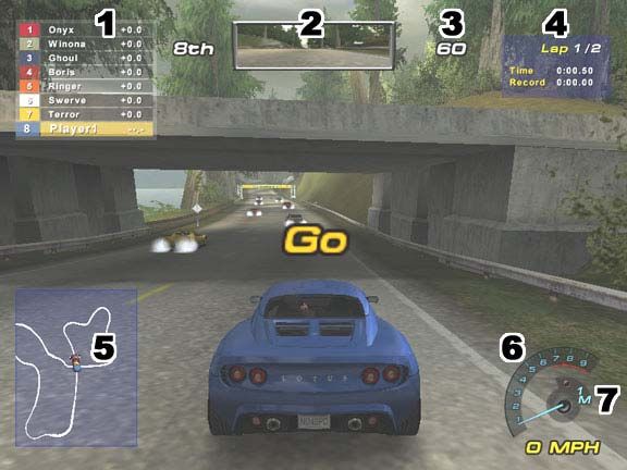
CHAPTER 1 – INTRODUCTION

     Regulatory Notices
     FCC Notices (United States)
     Electromagnetic Interference (EMI) is any signal or emission radiated in free space or conducted along power or
     signal leads, that endangers the functioning of radio navigation or other safety service or seriously degrades,
     obstructs, or repeatedly interrupts a licensed radio communications service. Radio communications services
     include, but are not limited to AM/FM commercial broadcast, television, cellular services, radar, air-traffic
     control, pager, and Personal Communication Services (PCS). These licensed services, along with unintentional
     radiators such as digital devices, including computer systems, contribute to the electromagnetic environment.
     Electromagnetic Compatibility (EMC) is the ability of items of electronic equipment to function properly
     together in the electronic environment. While this computer system has been designed and determined to be
     compliant with regulatory agency limits for EMI, there is no guarantee that interference will not occur in a
     particular installation. If this equipment does cause interference with radio communications services, which can
     be determined by turning the equipment off and on, you are encouraged to try to correct the interference by
     one or more of the following measures:
     •   Reorient the receiving antenna.
     •   Relocate the computer with respect to the receiver.
     •   Move the computer away from the receiver.
     •   Plug the computer into a different outlet so that the computer and the receiver are on different branch
         circuits.
     If necessary, consult a Regulatory EMC representative of GLOBAL VR or an experienced radio/television
     technician for additional suggestions. You may find the FCC Interference Handbook, to be helpful. It is
     available from the U.S. Government Print Office, Washington, DC 20402.
     This device has been tested and complies with the limits for a Class A digital device pursuant to Part 15 of the
     FCC Rules. These limits are designed to provide reasonable protection against harmful interference when the
     equipment is operated in a commercial environment. This equipment generates, uses and can radiate radio
     frequency energy, and if not installed and used in accordance with the instruction manual, may cause harmful
     interference with radio communications. Operation of this equipment in a residential area is likely to cause
     harmful interference, in which case you will be required to correct the interference at your own expense.
     Operation is subject to the following conditions:
     •   This device may not cause harmful interference.
     •   This device must accept any interference received, including interference that may cause undesired
         operation.

4                                                                                                             GLOBAL VR
                                                                                          040-1201-01 Rev. C 5/28/2004
CHAPTER 1 – INTRODUCTION

       Need For Speed™ Description
       GLOBAL VR presents full-throttle driving action with Need For Speed™.
       Get behind the wheel of the world’s top high-performance cars, including the 450-horsepower Dodge Viper
       GTS, the nimble Lotus Elise, the BMW Z8 and the fastest production Corvette ever made, the Z06. With a mix
       of high-end American muscle and top European exotics, Need For Speed has cars that will appeal to all players.
       With remarkable car detail and state-of-the art special effects, the graphics of Need For Speed are second-to-
       none. The sky is reflected in the surface of your car. Smoke pours from your tires when you punch it off the
       line. Leaves blow from trees as you rocket past. Of course, it’s hard to notice these details when you’re tearing
       down a mountain road at 160 with a Z8 two inches from your right rear quarter panel.
       Need For Speed features a player-selectable difficulty system that provides easier handling for beginning players
       and more challenging realistic driving physics for experienced drivers. The driving experience is further
       heightened with 6-speaker surround sound (3-speaker in upright cabinets) and force-feedback steering. Need
       For Speed is linkable, allowing blistering head-to-head competition for up to 4 players.

       Need For Speed™ GT Upgrade
       The GT Upgrade provides the following new features:
       •   4 New Cars. Porsche 911 Turbo – McLaren F1 – Mercedes CLK GTR – Ford Crown Victoria Police Cruiser.
       •   New Shadow Attack Play Mode. Players challenge the best time on each track in a head-to-head race
           against the top player’s “shadow.”
       •   Improved Handling. New handling physics and faster gameplay make Need For Speed GT the most
           exciting driver on the market.
       •   New Marquee Artwork. Players will know that you’ve installed the latest Need for Speed software.
       •   New Operator Features. The software update adds these features to the operator menus:
           –   The Machine Menu adds a Monitor Gamma Setting. This allows the operator to adjust the relative
               brightness of the monitor to compensate for age-related dimming. The default value is 1.0. The
               maximum allowed value is 3.97.
           –   The Options Menu adds a Clear Each High Score setting. By default, each high score on the cabinet is
               erased after 30 days. This option allows the operator to choose to erase high scores Never, in 7 days,
               or in 30 days (default).
           –   The Games Stats menu adds the new cars to the available statistics.
           –   The Machine and Sound menus now show the cabinet style (sit-down or upright).

Need For Speed™ GT System Documentation                                                                                    5
040-1201-01 Rev. C 5/28/2004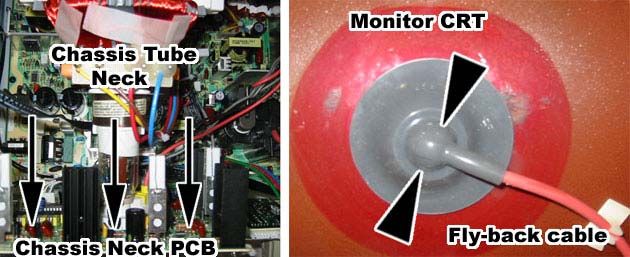
CHAPTER 1 – INTRODUCTION

     Cabinet Models
     Need for Speed comes in 3 cabinet models: standard, deluxe, and upright. The models share common
     hardware, but have slightly different set-up and service procedures. Unless otherwise noted, the procedures in
     this manual apply to all models.

         Standard Cabinet                                        Height = 74"                            Upright Cabinet
                                                 Height = 76"

         Driving Seat

                                                                                                                     Optional Upright
                                                                                                                     Seat Assembly

                                                                          Depth = 54"
                 Width = 34"    Depth = 62"                                                                    Width = 27"

                                                                                         UPRIGHT
                               STANDARD

                                          Height = 82"

                                                                                Deluxe Monitor Console

                                                                                        Deluxe Driving Console

                                                                                                      Driving Seat

                                                                Depth = 84"
                                                                                        Width = 40"

                                                                     DELUXE

         Figure 1 – Cabinet Styles

6                                                                                                                GLOBAL VR
                                                                                             040-1201-01 Rev. C 5/28/2004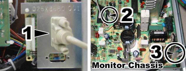
CHAPTER 2 – INSTALLING A NEW CABINET

Chapter 2 ---- Installing a New Cabinet

       Use the following procedures to setup your game:
       •   Standard Cabinet. Basic Cabinet Setup (page 7) + Standard Cabinet Installation (page 8).
       •   Deluxe Cabinet. Basic Cabinet Setup (page 7) + Deluxe Cabinet Installation (page 10).
       •   Upright Cabinet. Basic Cabinet Setup (page 7) + Upright Cabinet Installation (page 13).

       Basic Cabinet Setup (All Models)
       Use the following procedure to install a new cabinet:
       1. Carefully remove the cabinet from the shipping container. Give yourself plenty of space around the cabinet
          as you remove it from the shipping container. Inspect the exterior of the cabinet for any damage.
       2. Remove the keys from the coin return slot. Open the coin door to locate the second set of keys. See Figure
          2. On the deluxe model, the coin door and cash box are located on the driving console, not the main
          cabinet.

                                                                  Second Set
                            Coin Door                             of Keys

                      First Set of Keys

                       Cash-Box Door                              Cash-Box and
                                                                  Loose Parts

           Figure 2 – Coin Door and Cash-Box Door

       3. Open the cash-box door and remove the loose parts inside the cash box. You will find the following items
          (may vary with cabinet style):
           –   GLOBAL VR Instruction Manual (this document)
           –   10/100 Base-T Network cable
           –   10/100 Base-T Crossover coupler
           –   AC power cord
           –   T-25 Torx Security Bit
       4. Remove the back door from the cabinet and inspect the computer system. Verify that all cables and wires
          are securely connected to the computer. See page 52 for a guide to the cable connections.
       5. Connect the wall cord to a grounded (3-terminal) AC wall outlet.
       6. Power ON the cabinet using the On/Off switch located on the lower rear of the cabinet to verify proper
          operation.

Need For Speed™ GT System Documentation                                                                                7
040-1201-01 Rev. C 5/28/2004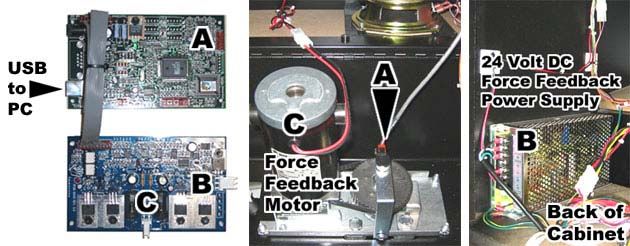
CHAPTER 2 – INSTALLING A NEW CABINET

     Standard Cabinet Installation
     Standard Cabinet Driving Seat Installation
     Locate the hardware used to assemble the driving seat inside the cash box. There are (8x) ¼-20 x 1" hex bolts
     with lock washers to secure the seat runners to the cabinet, and (8x) ¼-20 x 1" T-25H Torx bolts with lock
     washers and fender washers to secure the driving seat to the runners.
     1. The seat runners are installed backwards for shipping. Remove the (4x) hex bolts holding each seat runner
        inside the cabinet using a 7/16" socket wrench. See item A in Figure 3.
     2. Pull the seat runners out, flip them over, and reinsert them. Attach the runners using the (4x) hex bolts with
        lock washers for each bracket. The angled end of the seat runners should be pointed out and away from
        the cabinet as shown in item C of Figure 3.

         Figure 3 – Installing the Seat Runners

     3. Slide the driving seat onto the seat runners. Leave enough space to connect the wire harnesses.
     4. Locate the two wire harnesses inside the driving seat and inside the cabinet where the seat runners are
        installed. Connect each wire harness together as shown in item A of Figure 4. The connectors are keyed to
        prevent incorrect wiring.
     5. Slide the driving seat towards the cabinet while guiding the wire harnesses inside. Attach the driving seat
        to the seat runners using (4x) ¼-20 T-25H Torx screws with lock washers and fender washers. Repeat for
        each side of the driving seat. See item B of Figure 4.

         Figure 4 – Attaching the Driving Seat to the Runners

8                                                                                                            GLOBAL VR
                                                                                         040-1201-01 Rev. C 5/28/2004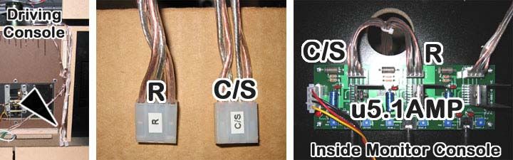
CHAPTER 2 – INSTALLING A NEW CABINET

       Standard Cabinet Marquee Setup
       1. Rotate the marquee forward towards the front of the cabinet as shown in Figure 5.

           Figure 5 – Installing the Standard Cabinet Marquee

       2. Install the marquee support bracket on the backside of the marquee using (6x) ¼-20 x 1" hex bolts. Install
          the bracket with the sharper angle towards the top of the marquee. See item A in Figure 6. Secure the top
          of the bracket to the marquee first, and then install the bottom bolts. Align the bottom holes in the bracket
          by bending the marquee backwards slightly.

           Figure 6 – Installing Marquee Support Bracket

       The standard cabinet is now ready for game play.

Need For Speed™ GT System Documentation                                                                                   9
040-1201-01 Rev. C 5/28/2004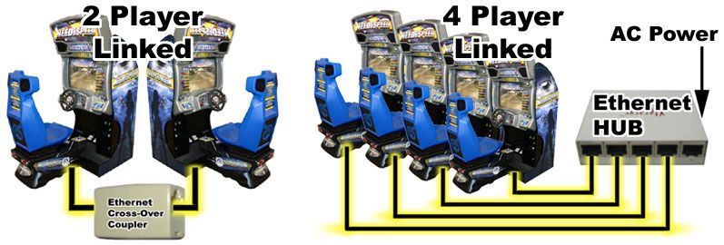
CHAPTER 2 – INSTALLING A NEW CABINET

     Deluxe Cabinet Installation
     Begin by removing the monitor console, driving console, and driving seat from the packaging. It is suggested
     that you do the final assembly at the location were the game will be played. This way each separate console
     and seat will have plenty of clearance to pass through normal size doors in your location.
     1. Secure the bottom bracket of the front monitor bezel to the monitor console with (3x) ¼ -20 x 1" hex bolts
        and washers. See below.

                                Front Monitor Bezel

                          SWING TO
                          OPEN/CLOSE
                                                                                                           Bottom
                                                                                                           Bracket
           Monitor
           Console

                                                                  (3x) 1/4-20 x 1" Hex Bolts and Washers

         Figure 7 – Securing the Front Monitor Bezel

     2. Locate the console rails inside the monitor console. Use (8x) ¼-20 x 2" Torx-security bolts, (8x) ¼ fender
        washers, and (8x) ¼" lock washers to secure the rails to the monitor console. Do not tighten the bolts all
        the way down until the last step in these instructions. See the figure below.

         Figure 8 – Attaching the Console Rails, and Mating the Consoles

     3. Slide the driving console onto the rails. Leave enough room between the two consoles so that you can get
        your hand in and connect the wiring harnesses between the 2 consoles. See the figure above.

10                                                                                                           GLOBAL VR
                                                                                         040-1201-01 Rev. C 5/28/2004
CHAPTER 2 – INSTALLING A NEW CABINET
4. On the monitor console, there are 3 wires hanging out the right-side hole. See the figure below. These
connect to separate PCB cards on the back of the driving console.
– (1) is a 6-pin connector that runs to the monitor control panel behind the coin door.
– (2) is a 3-pin connector that connects to the power force feedback card.
– (3) is a USB cable that connects to the force feedback controller card.
Figure 9 – Connecting Cables from the Monitor Console to the Driving Console
5. On the back of the driving console are 4 main wire harnesses that connect and power the driving controls
and buttons. See the figure below. These wire harnesses will connect to points inside the monitor console.
– (1) is a 4-pin power connector that runs to a 4-pin mating connector from the computer power supply
mounted on the floor of the monitor console.
– (2) is a 37-pin connector that runs to the 37-pin port on the back of the computer.
– (3) is a 25-pin connector that runs to the 25-pin port on the back of the computer.
– (4) is a 3-pin grounding wire that runs to the 3-pin mating connector from the AC panel in the monitor
console. It is very important to connect the grounding wires between the 2 consoles to assure a reliable
operating cabinet.
Figure 10 – Connecting Cables from the Driving Console to the Monitor Console
Need For Speed™ GT System Documentation 11
040-1201-01 Rev. C 5/28/2004CHAPTER 2 – INSTALLING A NEW CABINET
6. On the back of the driving console is a wire harnesses with two 4-pin connectors. This harness connects to
the u5.1AMP on the inside of the monitor console, as shown in the figure below. You will need to run the
audio wires through the hole just above the u5.1AMP.
– The (R) wire connector connects to the Rear Audio port.
– The (C/S) wire connector connects to the Center/Base audio port.
Figure 11 – Connecting the Driving Console Speakers
Deluxe Cabinet Driving Seat Installation
1. Follow the procedure on page 8 to install the driving seat.
2. Once all the wires are connected between the driving seat and the two consoles, power the cabinet ON.
Go into the Operator Menu and verify all the driving controls and ensure that sound is coming out from the
correct speakers by using the Player Control test and the Sound test.
Figure 12 – Bolting the Driving Console to the Monitor Console
3. When testing is complete, push the driving console onto the monitor console as shown above. Make sure
the wire harnesses will not be pinched or damaged when you push the two consoles together. Insert the
bolts on the driving console first, and make sure they connect with the rails on the inside before tightening.
If the holes in the rail do not line up with the holes in the cabinet, insert a small screwdriver in the hole of
the cabinet to slide the rails into place so the bolts will connect with the mounting holes.
The deluxe cabinet is now ready for game play.
12 GLOBAL VR
040-1201-01 Rev. C 5/28/2004CHAPTER 2 – INSTALLING A NEW CABINET
Upright Cabinet Installation
Standard Upright Installation
When used in the standard configuration, without a driving seat, the upright cabinet requires no additional
installation. The driving pedal components are shown in Figure 13. These components need to be removed
and reconfigured if the optional seat assembly is installed. Refer to the following section for more information.
Brake and Gas
Pedal Connectors (4x) 2-1/4" Torx Security Screw
+ Lock Washer
+ Fender Washer
(3x) 1-3/4" Torx Security Screw
+ Lock Washer Brake and Gas Pedals
+ Fender Washer
Pedal Mounting Plate and Panel
3/4" Wood Screw
Foot Panel Bracket
Figure 13 – Standard Upright Configuration Installation/Removal
Upright Installation with Seat Assembly
The optional seat assembly is shipped separately from the upright cabinet. Use the following procedure to
remove the standard pedal configuration, mount the pedals on the seat assembly, and connect the seat
assembly to the cabinet:
1. Turn cabinet power OFF.
2. See Figure 13 on page 6. Remove the (3x) 1-3/4" Torx screws holding the back of the foot panel bracket
to the cabinet. Remove the 3/4" wood screw on the left side of the foot panel bracket.
3. Slowly pull the foot panel bracket back from the cabinet, exposing the brake and gas pedal connectors.
Unplug the pedal connectors.
4. Remove the entire foot panel bracket and pedals from the cabinet.
5. Remove the (4x) 2-1/4" Torx screws holding the pedal mounting plate to the foot panel bracket.
6. Remove the (8x) Torx machine screws holding the pedals to the pedal mounting plate. Pull the pedals and
cables free from the pedal mounting plate.
7. Use the (8x) Torx machine screws to mount the pedals to the seat assembly. Thread the cables through the
hole and pull them to the front. See Figure 14 on page 14.
Need For Speed™ GT System Documentation 13
040-1201-01 Rev. C 5/28/2004CHAPTER 2 – INSTALLING A NEW CABINET
1-3/4" Torx Security Screw
+ Lock Washer
+ Fender Washer
Brake Pedal Connector
3/4" Wood Screw
(optional) Gas Pedal Connector
3/4" Wood Screw
(optional)
3" Torx Security Screw
+ Lock Washer
+ Fender Washer
Tread-Plate Panel
Figure 14 – Optional Seat Assembly Installation/Removal
8. Slide the seat assembly onto the front of the upright cabinet, leaving enough room to connect the cables.
Connect the gas and brake pedal to the matching connectors on the cabinet. Use wire ties or rubber bands
to secure excess cable length.
9. Slide the seat assembly the rest of the way onto the cabinet. Use the (3x) 3" Torx screws with lock and
fender washers (included with the seat assembly) to hold the tread-plate panel down.
10. Use the 1-3/4" Torx screws with lock and fender washers from step 2 to secure the front of the tread-plate
panel to the front of the upright cabinet.
11. If desired, secure the sides of the tread-plate panel to the cabinet using (4x) 3/4" wood screws.
The upright cabinet with seat assembly is now ready for game play.
14 GLOBAL VR
040-1201-01 Rev. C 5/28/2004CHAPTER 2 – INSTALLING A NEW CABINET
Linking Cabinets
You can link up to 4 cabinets together for head to head competition. The necessary cables and hardware are
provided with each game to link 2 cabinets together. A NFS Linking Kit is required to link more than 2 cabinets
together. Once the cabinets are linked in hardware and software, players can choose to play individually, or
against other players. Follow the instructions below to link your NFS cabinets correctly.
Figure 15 – Installing Network Cables
1. Locate the 10ft Ethernet cable and Ethernet Cross-Over coupler, which should be inside the cash box of
each cabinet.
2. Connect an Ethernet cable to the Ethernet connector at the back of each cabinet next to the power switch.
3. If connecting two cabinets, connect the two cables to one cross-over coupler (don't use two couplers).
4. If connecting three or four cabinets, connect the cables to the Ethernet hub. The hub includes an AC
power adapter, which must be plugged in and powered ON. Do not use any of the cross-over couplers
when using a hub.
5. When the hardware has been connected, go into the Operator Menu on each cabainet, and adjust the
Cabinet Link ID number shown by the arrow in the picture below. Each cabinet must have a unique
number: 1 , 2 , 3 , or 4. When you change the Cabinet Link ID number, the game software will
automatically reboot the computer when you exit the Operator Menu to make the changes take effect.
If you have a duplicate cabinet number among the linked cabinets, you will get an error message on screen
on both of the cabinets that have the duplicate cabinet link ID number. Correct the duplicate Cabinet Link
ID numbers in the Operator Menu to make the error message go away.
Figure 16 – Checking Link Status
Need For Speed™ GT System Documentation 15
040-1201-01 Rev. C 5/28/2004CHAPTER 2 – INSTALLING A NEW CABINET
Installing an External Monitor
Use the following procedure to install an external monitor:
1. Turn the cabinet power OFF. Locate the video card on the rear of the PC. The card provides an S-Video
connection.
2. Connect an S-Video cable to the video card. Run the cable out the back of the cabinet, and connect it to
the external monitor.
3. Plug the PS/2 keyboard into the purple-colored PS/2 port on the back of the computer. Turn the cabinet
power ON, and allow the game software to start.
4. With the cabinet powered ON, and the game running, press the Windows Start key on the keyboard
(between the Ctrl and Alt keys). This will launch the Windows Start menu.
5. Use the cursor keys to select My Computer, and press Enter. This will launch Windows Explorer:
Figure 17 – Using the Start Menu and Windows Explorer to Launch Control Panel
6. Press the Tab key to move the highlight down to the box labeled Other Places.
7. When Other Places is highlighted, use the cursor keys to move the highlight to the item, Control Panel.
The control panel will be displayed:
Figure 18 – Selecting the Display Control Panel
16 GLOBAL VR
040-1201-01 Rev. C 5/28/2004CHAPTER 2 – INSTALLING A NEW CABINET
8. Move the highlight to the item Display and press Enter. This will show the Display control panel.
9. Use the Tab and cursor keys to highlight the Themes tab, and then use the left/right cursor keys to move
to the Settings tab.
Figure 19 – Selecting the Settings Tab in the Display Control Panel
10. Use the Tab key to move down to the Advanced button, then press Enter. The following window will be
displayed:
Figure 20 – Selecting the Video Card Name Tab
11. Use the Tab and cursor keys to move to the GeForce4 tab. (The name of the video card will change
depending on cabinet age and model). The following window will be displayed:
Figure 21 – Choosing a Display Pair with Cloning
12. Use the Tab and cursor keys to change the nView Modes option to "Clone", and the Display pair:
option to "Analog Display + TV". After making those changes, move down to the OK button and press
Enter.
Need For Speed™ GT System Documentation 17
040-1201-01 Rev. C 5/28/2004CHAPTER 2 – INSTALLING A NEW CABINET
13. You should now see the video image displayed on the external monitor. You will also see the following
dialog box displayed:
Figure 22 – Confirming Display Settings
14. Press the Tab key to select Yes, and then press Enter. This will save the setting.
15. If you do not see the image in the external monitor, check the S-Video cable, and check that the external
monitor is set to receive video from the S-Video input.
16. Turn the cabinet power OFF, and unplug the keyboard from the computer.
17. Turn the cabinet power ON. The game can now be viewed on the external monitor.
Checking and Setting the Computer Clock
The game computer is shipped from the factory with the correct date set. If this date becomes lost or
corrupted, you may be unable to install software upgrades. Perform this procedure only if you suspect that the
computer clock is set incorrectly:
1. Turn the cabinet power OFF. Plug the PS/2 keyboard into the purple-colored PS/2 port on the back of the
computer. Turn the cabinet power ON.
2. With the cabinet powered ON, and the game running, press the Windows Start key on the keyboard
(between the Ctrl and Alt keys). This will launch the Windows Start menu:
Run Dialog Box
2
Terminal Window
3
1 Windows Start Menu
Figure 23 – Changing the Date on the Computer
3. Use the cursor keys to select Run..., and press Enter. This will launch the Run dialog box.
4. Type cmd into the dialog box and press Enter. This will launch a terminal window.
5. Type date and press Enter. The current date will display.
6. If the date is correct, type exit to close the window and return to the game.
18 GLOBAL VR
040-1201-01 Rev. C 5/28/2004CHAPTER 2 – INSTALLING A NEW CABINET
7. If the date is not correct, type in a new date. The format is / / . For example, you
might type in 6/1/2004, and the press Enter. The date is now set. Type exit to close the window and return
to the game.
8. Turn the cabinet power OFF before unplugging the keyboard.
Checking Game Dongle
Figure 24 – Game Dongle
The cabinet comes with a USB game dongle to activate the game software. The game dongle plugs directly into
the USB ports on the back of the computer. When the USB dongle is installed and working properly a red LED
light will illuminate inside the dongle. In order for a dongle to be recognized correctly, it must be inserted into
the USB port before the cabinet is powered ON. If for some reason the USB Dongle is not recognized, power
the cabinet OFF then ON to see if this resolves the problem.
The dongle supplied with the cabinet is specific to that game and software version. Some software upgrades
may require you to upgrade the dongle after you upgrade the software.
Need For Speed™ GT System Documentation 19
040-1201-01 Rev. C 5/28/2004CHAPTER 3 – UPGRADING AN OLDER CABINET
Chapter 3 ---- Upgrading an Older Cabinet
Upgrading a cabinet to Need for Speed GT software requires the following steps:
• Installing the Software
• Installing the Cabinet Artwork
Kit Contents
The Upgrade Kit contains the following items:
• (1) Emergency Recovery Disk
• (2) NFS Game Software Disks, version 1.1
• (1) ¼-20H Torx Security Bit
• (1) of the following:
– Marquee Artwork Panel (Standard)
– Marquee Artwork Panel (Deluxe)
– Marquee Artwork Panel (Upright)
• Upgrade Kit Instruction Manual
Installing the Upgrade
This upgrade kit updates the software from version 1.0 to version 1.1. Total install time for one cabinet is
approximately 15 minutes. If the cabinet links to other cabinets, you must unlink it before installing the new
software. Unlink the cabinet by disconnecting the Ethernet cable from the back of the cabinet. All linked
cabinets must run the same game software version.
Follow the instructions below to install the software update. Please be aware that this process will erase all
cabinet settings including sound and coin/game audits.
Note: When the instructions say “reboot the computer,” this is the same as turning the cabinet off by
unplugging the power cord, and then plugging it back in again.
1. The cabinet should be powered on with the game running. Open the coin door and press the red operator
button. This will launch the Operator Menu.
2. Use the Operator Menu to record the following information:
– Machine Menu: Cabinet Volume _____ , Attract Volume _____% , and Cabinet Link ID# _____
– Options Menu: Credit Display __________ , Cost/Credits per Play______
– Coin/game stats (optional)
3. Open the rear of the cabinet to gain access to the computer.
4. Open the CD drive and insert the CD labeled Emergency Recovery Disk. Reboot the computer
5. After reboot, the CD will automatically start installing. After about 30 seconds, the monitor will display a
status window labeled “Image Center 5.0 – Scripting Progress.”
6. When the process finishes, you will see the message “Please remove the CD and reboot your Need for
Speed System.” Remove the Emergency Recovery Disk from the drive.
DO NOT PUT THE GAME CD IN THE DRIVE YET.
7. Reboot the computer.
8. When the computer restarts, it will display the message “XP Embedded Install. Finalizing settings... Please
wait for reboot.” Allow this process to finish. The computer will eventually reboot itself. DO NOT
INTERRUPT THIS PROCESS OR PRESS ANY KEYS UNTIL COMPLETE.
20 GLOBAL VR
040-1201-01 Rev. C 5/28/2004CHAPTER 3 – UPGRADING AN OLDER CABINET
9. When the automatic reboot is complete, you will see a black screen with the Windows Start menu and
taskbar.
10. Open the CD drive and insert Need For Speed Disk 1 of 2. The installer will automatically start (wait
about 30 seconds). This install process will take approximately 10 minutes. You will see several different
windows appear while game files copy to the hard drive.
11. When the first CD is complete, the computer will eject the CD. The screen will tell you to insert CD Disk 2.
Remove CD Disk 1 of 2 and insert Need For Speed CD Disk 2 of 2.
12. The computer will copy the remaining files from Disk 2 and will reboot when finished.
13. After reboot is complete, the cabinet will check for a valid NFS game dongle. Then the game will prompt
you to perform a set of simple calibration tasks.
14. When the calibration is complete, the game attract mode will begin. Press the operator button behind the
coin door to enter the Operator Menus. You will need to set the Sound Volume, Attract Mode Volume, and
Cabinet ID# (for linked cabinets). You will have recorded these numbers in Step 2. You should play one
complete game to ensure correct operation.
15. Once the Cabinet ID# has been set, you can reconnect the Ethernet cable to the back of the cabinet. Note
that some cabinets may automatically reboot when linked. For more information about the linking process,
refer to the Need for Speed Instruction Manual.
16. After the install process is complete, you may remove CD Disk 2 of 2. Keep the CD set in a safe place in
case you need to reinstall the software.
You have now completed the software installation process for this cabinet. Repeat the process for any other
NFS cabinets you have.
Need For Speed™ GT System Documentation 21
040-1201-01 Rev. C 5/28/2004CHAPTER 3 – UPGRADING AN OLDER CABINET
Upgrading the Marquee ---- Standard Cabinet
Use the following procedure to install the new marquee artwork in the standard NFS cabinet:
1. Using a ¼-20H Security Torx bit (included), remove the (6x) screws holding the marquee shield.
2. Remove the old artwork. Insert the new artwork included in the update package.
3. Reinstall the shield. Take care not to scratch the shield or artwork during installation.
Marquee Shield New Marquee Artwork
(6x) Torx Screws
Cabinet Marquee Light
Figure 25 – Standard Cabinet Marquee
Upgrading the Marquee ---- Deluxe Cabinet
Use the following procedure to install the new marquee artwork in the deluxe NFS cabinet:
1. Remove the (9x) screws holding the rear, hinged marquee cover plate in place. DO NOT remove the (3x)
screws below the hinge. CAUTION: The front monitor bezel may slide forward after the last screw is
undone. Hold the bezel in place to prevent damage.
2. Tilt the plate back on the hinge. You may need a stepladder to access the marquee interior.
3. Using a Philips screwdriver, remove the two top retainer blocks. Leave the bottom and side blocks in place.
Remove the old artwork.
4. Install the new artwork. Take care not to scratch the clear shield or artwork during installation.
5. Replace the retainer blocks holding the artwork in place.
6. Tilt the hinged marquee cover plate back in place and reinstall the (9x) screws.
Marquee Retainer Blocks
Marquee Artwork
Rear Hinged
Marquee Cover
(9x) Screws and Washers
SWING OPEN
Figure 26 – Deluxe Cabinet Marquee
22 GLOBAL VR
040-1201-01 Rev. C 5/28/2004CHAPTER 4 – GAME SETUP
Chapter 4 ---- Game Setup
This chapter describes how to use the Game Operator menu to perform basic cabinet set up.
All game audits, game adjustments, and control diagnostics are options of the Game Operator Menu. Press the
red operator button behind the coin mech door as shown in the figure below:
Figure 27 – Launching the Game Operator Menu
After you press the operator button, the Game Operator menu will appear. There is no mouse pointer seen
when using the Operator Menu buttons to navigate the Game Operators Menu; instead, each option or menu
button will highlight when it is ready to be selected.
Setting Game Options and Resets
Once in the Operator’s Menu you will use driving controls to navigate and select. Use the Up and Down buttons
to scroll through the settings. Use the Select button to confirm, and the Back button to navigate back a menu
screen. When you are finished making adjustments, press the Back button repeatedly to exit the menu and
return to attract mode. See the following example:
Figure 28 – Setting Cabinet Volume
1. Use the Operator menu Up and Down buttons to navigate and highlight a game option.
2. Press the Select Button to select the game option. The game option should now turn to red, as shown by
the arrow in step 2 of the picture above.
3. Use the Operator menu Up and Down buttons to scroll up and down through the available game settings,
shown by the arrow in step 3 of the picture above
4. When you have the correct game setting highlighted, press the Back button again to set the new game
option. The game option will now turn back to yellow, as shown in step 4 of the picture above.
Need For Speed™ GT System Documentation 23
040-1201-01 Rev. C 5/28/2004CHAPTER 4 – GAME SETUP
Machine Menu
The Machine menu is the default screen displayed when you press the Operator Button. See below.
Figure 29 – Machine Menu
Following are the functions of the Machine menu:
• Status. Displays the Tournament Status of the cabinet. This is reserved for future use.
• Version. Displays the software version of this cabinet.
• Available Credits. Displays the number of credits inserted on this cabinet.
• Reset Credits. Resets the Available Credits number on this screen.
• Cabinet Volume. Sets the game play sound volume. Options are 0 - 100 in increments of 10.
• Attract Volume. Sets the attract mode volume as a percentage of the cabinet’s volume volume. Options
are 0 - 100 in increments of 10.
• Attract Sound Mode. Sets attract mode to be with sound or without. Options are Always, Sometimes,
and Never. The Sometimes setting will play sound in the attract mode movie 10% of the time.
• Monitor Gamma Setting. Sets the relative brightness of the monitor to compensate for age-related
dimming (cabinet age, not your age!). Higher numbers increase the brightness. The default value is 1.0.
The maximum allowed value is 3.97.
• Cabinet Link ID#. Sets the Cabinet ID number for linked cabinets. Each cabinet you link must have a
unique Cabinet ID number (1, 2, 3, or 4).
24 GLOBAL VR
040-1201-01 Rev. C 5/28/2004CHAPTER 4 – GAME SETUP
Game Options
Figure 30 – Setting Game Options
The Game Options menu is used to set up the type of money or credits used at your location, the amount of
coins that are needed to start a game, and game play difficulty.
• International Settings. Defines what type of money that will be used in this cabinet. This option is set by
the USB Game Dongle
• Credit Display. Sets whether Money or Credits are used to play this cabinet.
• Coins Per $. Sets how many coin drops it takes to reach a dollar. In the USA this would be 4 (4 quarters
per dollar). In the UK this would be 10 (10 pence per pound). Options are 1–20.
• Free Play. Sets free play ON or OFF.
• Coins Per Play. Sets how many coins it takes to play. Options are 1–10.
• Clear Each High Score. Sets the number of days to keep high scores. By default, each high score on the
cabinet is erased after 30 days. This option allows the operator to choose to erase high scores Never, in 7
days, or in 30 days (default).
• Skill Level. Sets the time to reach each checkpoint in the race. Default skill for each racetrack is medium
or C. Options are A (easiest), B, C, D, or E (hardest).
• Number of Laps. Sets the number of laps for each racetrack. Options are 1–5.
Need For Speed™ GT System Documentation 25
040-1201-01 Rev. C 5/28/2004CHAPTER 4 – GAME SETUP
Game Resets
Figure 31 – Game Resets Screen
• Restore Factory Settings. Sets the cabinet to the default settings below.
Table 1 – Factory Default Settings
US (Dollar) UK (Pound)
International Setting USA UK
Credit Display Money Money
Coins per $ 4 10
Free Play OFF OFF
Cost Per Play $1.00 £1.00
Game Volume 50 50
Attract Volume 100% 100%
Skill Level on All Racetracks C C
• Reset Coin Stats. Resets the Coin Stats for the cabinet.
• Reset Game Stats. Resets the Game Stats on the cabinet.
• Reset Track Records. Resets the Track Records for the cabinet.
26 GLOBAL VR
040-1201-01 Rev. C 5/28/2004CHAPTER 4 – GAME SETUP
Coin Stats
Figure 32 – Checking Coin Statistics
The Coin Stats menu shows the total number of coins collected for the cabinet, as well as the last date and
time the stats were reset. The Coin Stats can be reset through the Game Resets menu.
Game Stats
Figure 33 – Checking Game Statistics
The Game Stats menu shows the total number of games played, which racetrack was used most, and car
features used in the game. Use the Previous Screen and Next Screen buttons to move through the available
Game Stats pages. You can reset Game Stats data through the Game Resets menu.
Need For Speed™ GT System Documentation 27
040-1201-01 Rev. C 5/28/2004CHAPTER 4 – GAME SETUP
Controls Menu
Figure 34 – Testing Game Controls
The Controls Menu allows the operator to test the cabinet controls. The Controls Menu is a graphical
representation of all the controls on the cabinet. If you press a button, move the steering wheel, step on the
gas, or move the shifter, you should see the same action or movement on screen. To exit from this menu, press
the Start and View button at the same time (or press the Operator button).
• Buttons. When any button is pressed, it will light up on screen.
• Steering Wheel. Turn the Steering Wheel to the left or right. When it is working properly, you should see
a change in the numerical reading just above the center of the steering wheel.
• Gas & Brake Pedal. When you step on the pedals you will see the same action on screen. The numerical
readings show the high, low, and current values.
• Shifter. Moving the shifter up or down will appear on the screen. If you press the E-Brake button, it will
light up on screen.
• Credits. When you insert money or credit into the coin mech or bill validator, you will see CREDITS OK on
screen.
• Calibration. You can calibrate the steering wheel and pedals at any time by pressing the Start and Horn
buttons simultaneously. DO NOT touch the steering wheel during the calibration process as this is done
automatically with the Force Feedback motor. You will need to step on the gas and brake pedals when the
calibration process asks you on screen.
• Force Feedback Test. Validates that the Force Feedback motor and Immersion Controller cards are
working properly. Press the View and Horn buttons simultaneously to start the test. If everything is
working properly, the steering wheel should move to the left and right momentarily.
• Start Button, Leader Light and Brake Light. When you enter the Controls Menu, the Start button,
Leader Light and Brake Lights on the cabinet will begin to blink. If you do not see these lights blinking,
verify the bulb for that light is in working condition.
28 GLOBAL VR
040-1201-01 Rev. C 5/28/2004CHAPTER 4 – GAME SETUP
Monitor Calibration Test
When you begin the Monitor Calibration Test, use the Music button to start the test, and the View button to
scroll through the screens. To exit the Monitor Calibration Test, press the Horn button or the Operator button.
See below.
Color Calibration Screen Size Horizontal/Vertical Sync White Balance
Figure 35 – Performing Monitor Calibration Tests
Use the monitor calibration screens to evaluate monitor performance. Each screen is designed to help you align
the horizontal and vertical sync, or adjust the white balance and color hues.
Use the monitor control panel buttons to adjust the monitor. The monitor control panel is located next to the
Game Operator button. Use the buttons on the monitor control panel to select, adjust, and set the available
options.
Figure 36 – Monitor Control Panel
Need For Speed™ GT System Documentation 29
040-1201-01 Rev. C 5/28/2004CHAPTER 4 – GAME SETUP
Sound Test
Figure 37 – Sound Test Screen
The Sound Test menu will validate that each speaker is working properly on the cabinet. When you enter the
sound test, each speaker will begin to call out its speaker name one at a time. You should hear the words “Left
Front Speaker” coming out of the left front speaker on the cabinet, then 5 seconds later you should hear the
words “Right Front Speaker” coming out of the right front speaker, and so on. You can press the Start button
to stop the sound rotation and test one speaker at a time. The Sound test will continue to rotate sound through
each speaker until you exit the test. Exit the Sound test by pressing the Horn button.
The picture on the screen will show the cabinet style (sit-down or upright). Note that the upright cabinet does
not have rear speakers.
You should verify the audio connections on the computer to the u5.1AMP board if you find that sound is
coming from the wrong speaker, or your speakers are not working properly.
30 GLOBAL VR
040-1201-01 Rev. C 5/28/2004CHAPTER 5 – PLAYING A GAME
Chapter 5 ---- Playing a Game
Starting a Game
With the proper amount of coins inserted, press the red Start button next to the steering wheel. Begin by
choosing the track. Each track is rated by difficulty of play: Easy, Medium, or Hard. Turn the Steering wheel to
highlight the track you want to race, and use the gas pedal to select. As you highlight each race track across
the top of the screen, the race track map is displayed on the left showing the design of the course.
Figure 38 – Starting a Game
At the next screen you choose the car, car color, and transmission. Manual shifting will usually result in better
speed control, and faster race times. There is no clutch used for the manual shifter; only the gear shift is
needed.
Figure 39 – Choosing a Car
Figure 40 – Setting Handling and Performance Options
At any time during the car selection screens you can press the View and Music buttons to bring up the
Handling and Options menus. Press the View button to bring up the car handling menu and scroll through the
handling options. Each option changes the cars overall speed and the ability to grip to the road, once you have
the car handling selected the menu will disappear in 5 seconds.
Need For Speed™ GT System Documentation 31
040-1201-01 Rev. C 5/28/2004CHAPTER 5 – PLAYING A GAME
Press and hold the Music button to bring up the game options menu. Press the View, Look Back, and Horn
buttons while you have the Music button pressed to change the options in the menu.
• You can race by yourself on the track with no other cars by turning the AI off. Press the View button to
change this option.
• The Handicap option gives players a chance to win the race a little easier by slowing the AI cars down for
the last ¼ lap of the race, press the Look Back button to change this option.
• You can choose Low, Medium, or High Force Feedback on the steering wheel by pressing the Horn button
to change this option.
Once you have selected the available options for the track and your car, the game will begin to load. The next
screen shows the other players that are racing against you, and how each car is setup in the race:
Figure 41 – Competitor List
32 GLOBAL VR
040-1201-01 Rev. C 5/28/2004CHAPTER 5 – PLAYING A GAME
Playing a Game
Use the Steering Wheel, Gas, Brake and Shifter as in any driving game to control the car. The buttons can
enhance the game play by allowing you to look behind the car, change the view from the inside the car to the
front bumper, and honk at other cars. Hold the music button to change the song on the radio, or tap it to turn
the music off. Use the information on screen to tell you your position in the race, speed, and lap time as you
race against other players.
Figure 42 – Driving Screen Functions
1. Position in the race. As you move ahead of other drivers your position will move up. It also shows how
much ahead or behind you are of other drivers in time.
2. Rear View Mirror. Use this to look behind you as you drive, and block other drivers from passing you.
3. Check Point Time. This shows how much time is left for you to cross the next checkpoint in the race.
4. Laps and Race Time. This shows the total number of laps there on the racetrack, and how many you
have completed. The clock shows the current time for your lap and the best lap time recorded.
5. Track Map. This shows the map of the racetrack. Each colored dot represents the other drivers and their
location on the track.
6. RPM and Speed. This shows the RPM gauge for your car and the speed you are traveling
7. Shifter. The number shows what gear you are in, and the letter stands for whether you are driving an
Automatic or Manual transmission.
Need For Speed™ GT System Documentation 33
040-1201-01 Rev. C 5/28/2004CHAPTER 6 – SERVICE
Chapter 6 ---- Service
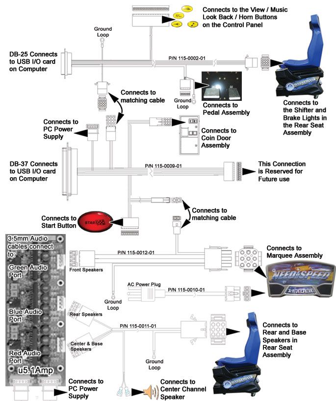
Cabinet Specifications
STANDARD CABINET DELUXE CABINET UPRIGHT CABINET
Height = 76" Height = 82" (shown with optional seat)
Width = 34" Width = 40" Height = 74"
Depth = 62" Depth = 82" Width = 27"
Depth = 54"
Figure 43 – Cabinet Dimensions
Hardware Features
– Pentium 4 computer
– Nvidia GeForce 4 graphics
– 1 Gigabyte DDR RAM
– 32-bit color
– Force-Feedback Steering
– 800 x 600 Super VGA monitor
34 GLOBAL VR
040-1201-01 Rev. C 5/28/2004CHAPTER 6 – SERVICE
Troubleshooting
Video Troubleshooting
Problem Cause Possible Solution
No picture on Power problem Verify the AC power connection to the monitor. You can
monitor verify that the monitor has power by looking for a small
glow in the neck of the CRT.
Bad video cable Verify that the video cable is firmly connected from the
monitor to the video card on the computer. While the
monitor is powered ON, unplug the video cable from the
monitor. You should see a message on screen saying No
Signal to verify the monitor is working.
Bad chassis PCB Verify that the fuses on the chassis PCB are good.
Picture is out of color Picture is dim or Use the monitor control panel to adjust the brightness and
or misaligned faded contrast settings. Adjust the monitor gamma setting (see
page 24).
Picture is out of color Use the monitor control panel to adjust the red, green,
and blue color settings.
Picture geometry is Use the monitor control panel to adjust the height and
misaligned width as well as other geometric adjustments to see if this
corrects the problem.
Distorted colors on Press the degausser button on the monitor control panel
screen to see if this corrects the problem.
Need For Speed™ GT System Documentation 35
040-1201-01 Rev. C 5/28/2004CHAPTER 6 – SERVICE
Audio Troubleshooting
Problem Cause Possible Solution
No audio Volume setting Enter the Operator Menu and adjust volume the volume
setting for the cabinet. Verify that the attract volume is ON.
Verify the adjustable volume setting on the audio amp is not
turned off.
Bad wiring Turn off the cabinet. Verify that all the wires are firmly
connected to each speaker. Verify that no wires are frayed
or improperly shorting to ground.
Blown speakers Remove the speaker’s grill covers, and visually inspect each
speaker is in working order. Run the Sound Test from the
Operator Menu to verify each speaker is working.
Bad audio amp You can verify the audio amp next to the Operator button is
working by installing it into another working cabinet. If that
is unavailable to you, plug a simple computer speaker into
the audio ports on the computer and verify that sound is
working from the computer.
Audio is distorted or Blown speakers Remove the speaker’s grill covers, and visually inspect each
muffled speaker is in working order. Run the Sound Test from the
Operator Menu to verify each speaker is working.
Faulty wiring A weak or low muffled sound is a sign of reversed speaker
wires. Check for reversed wires on each speaker.
Bad Power Supply A constant low hum in the speakers can be a faulty or bad
power supply.
Bad sound channel Bad audio amp You can verify the audio amp next to the Operator Button is
working by installing it into another working cabinet. If that
is unavailable to you, plug a simple computer speaker into
the audio ports on the computer and verify that sound is
working from the computer.
Blown Speakers Remove the speaker grill covers and visually inspect each
speaker is in working order. Run the Sound Test from the
Operator Menu to verify each speaker is working.
Bad Wiring Turn off the cabinet. Verify that all the wires are firmly
connected to each speaker. Verify that no wires are frayed
or improperly shorting to ground.
36 GLOBAL VR
040-1201-01 Rev. C 5/28/2004You can also read