A Virtual Reality visualization of the biosonar communication channel for live in the depths of the sea
←
→
Page content transcription
If your browser does not render page correctly, please read the page content below
UNIVERSITAT POLITÈCNICA DE CATALUNYA
      Facultat d’Informàtica de Barcelona

             FINAL MASTER THESIS
        Master of Innovation and Research in Informatics
            Computer Graphics and Virtual Reality

A Virtual Reality visualization of
  the biosonar communication
channel for live in the depths of
             the sea

                  Albert Gil Saavedra

                       Supervised by:
                DR. Antonio SUSIN SANCHEZ
                 Department of Mathematics

                           June 2020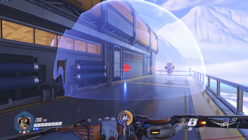
Abstract
    Underwater sound propagation is used as a means of communication by many
living beings in the deep sea. It is not only used as a communication channel, but
it also serves so that animals can recognize the surrounding environment by acting
as an underwater sonar.

    The work in this thesis addresses the visualization of this phenomena by devel-
oping a Virtual Reality Serious Game using Unity, where the players can live the
experience of seeing through sounds, and understand how human noise pollution
interferes with underwater life. We have created an underwater scene with its own
ecosystem and full of sounds, which allows the players to feel like being underwater.
Players will navigate freely in this scene, with the objective to reach deeper zones.
In this journey, they will lose the sight with the depth, and become dependent of
the sound waves to locate and discover its surroundings.

                                         1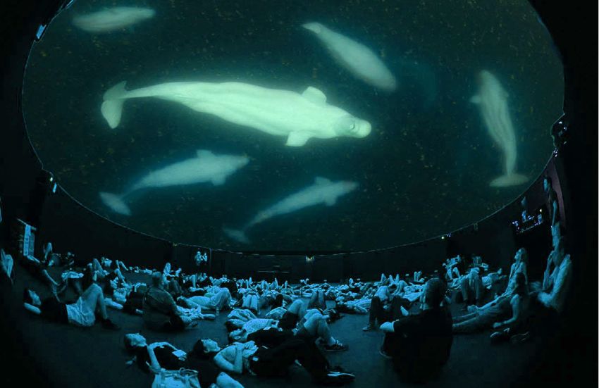
Contents

List of Figures                                                                                                                              4

1 Introduction                                                                                                                               5
  1.1 Motivation . . . . . . . . . . . . . . . . . . . . . . . . . . . . . . . . .                                                           6
  1.2 Objectives . . . . . . . . . . . . . . . . . . . . . . . . . . . . . . . . .                                                           7
  1.3 Work Scope . . . . . . . . . . . . . . . . . . . . . . . . . . . . . . . .                                                             8

2 State of the art                                                              9
  2.1 Sound Waves . . . . . . . . . . . . . . . . . . . . . . . . . . . . . . . 9
  2.2 Underwater Environments . . . . . . . . . . . . . . . . . . . . . . . . 11

3 Methodology                                                                     13
  3.1 Limitations . . . . . . . . . . . . . . . . . . . . . . . . . . . . . . . . 14

4 Description of the Application                                                                                                            16
  4.1 Environment . . . . . . . . . . . . . .                       .   .   .   .   .   .   .   .   .   .   .   .   .   .   .   .   .   .   16
      4.1.1 Fog Effect & Lighting . . . . .                         .   .   .   .   .   .   .   .   .   .   .   .   .   .   .   .   .   .   17
      4.1.2 Underwater Distortion Effect                            .   .   .   .   .   .   .   .   .   .   .   .   .   .   .   .   .   .   20
      4.1.3 Scene Design . . . . . . . . .                          .   .   .   .   .   .   .   .   .   .   .   .   .   .   .   .   .   .   22
      4.1.4 Boids . . . . . . . . . . . . . .                       .   .   .   .   .   .   .   .   .   .   .   .   .   .   .   .   .   .   25
  4.2 Sound Waves . . . . . . . . . . . . .                         .   .   .   .   .   .   .   .   .   .   .   .   .   .   .   .   .   .   31
      4.2.1 Distortion waves . . . . . . .                          .   .   .   .   .   .   .   .   .   .   .   .   .   .   .   .   .   .   36
  4.3 VR shaders implementation . . . . .                           .   .   .   .   .   .   .   .   .   .   .   .   .   .   .   .   .   .   37
  4.4 Gameplay . . . . . . . . . . . . . . .                        .   .   .   .   .   .   .   .   .   .   .   .   .   .   .   .   .   .   39

5 Conclusions & Future Work                                                    43
  5.1 Acknowledgements . . . . . . . . . . . . . . . . . . . . . . . . . . . . 45

References                                                                                                                                  46

A Ecosystem Catalogue                                                                                                                       48
  A.1 Animals: . . . . . . .    .   .   .   .   .   .   .   .   .   .   .   .   .   .   .   .   .   .   .   .   .   .   .   .   .   .   .   48
  A.2 Plants: . . . . . . . .   .   .   .   .   .   .   .   .   .   .   .   .   .   .   .   .   .   .   .   .   .   .   .   .   .   .   .   49
      A.2.1 Seaweeds: . .       .   .   .   .   .   .   .   .   .   .   .   .   .   .   .   .   .   .   .   .   .   .   .   .   .   .   .   49
      A.2.2 Coral Stones:       .   .   .   .   .   .   .   .   .   .   .   .   .   .   .   .   .   .   .   .   .   .   .   .   .   .   .   50
      A.2.3 Sponges . . .       .   .   .   .   .   .   .   .   .   .   .   .   .   .   .   .   .   .   .   .   .   .   .   .   .   .   .   50
      A.2.4 Shells: . . . .     .   .   .   .   .   .   .   .   .   .   .   .   .   .   .   .   .   .   .   .   .   .   .   .   .   .   .   50
  A.3 Rocks: . . . . . . . .    .   .   .   .   .   .   .   .   .   .   .   .   .   .   .   .   .   .   .   .   .   .   .   .   .   .   .   51

                                                        2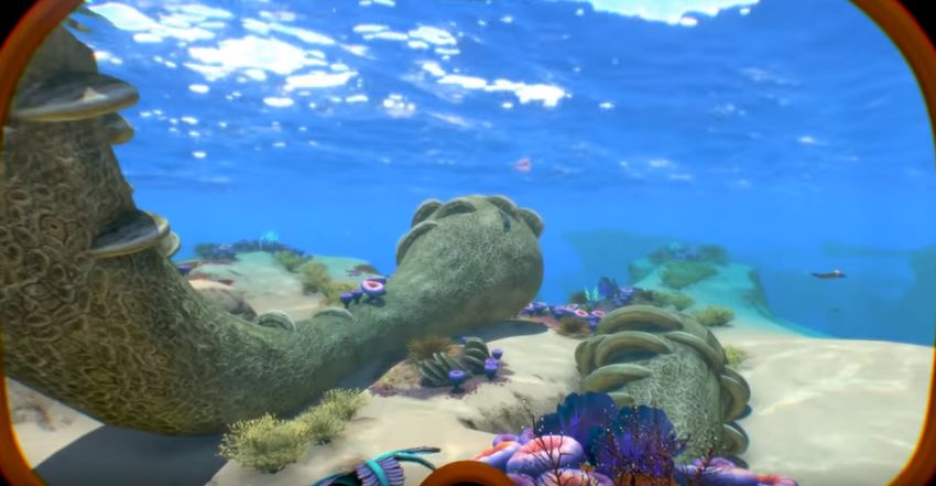
List of Figures

 1.1    Underwater environment scheme. . . . . . . . . . . . . . . . . . . . .                    5
 1.2    Sonar System used by sperm whales. . . . . . . . . . . . . . . . . . .                    6
 1.3    BIOSONAR 360’ Dome. . . . . . . . . . . . . . . . . . . . . . . . . .                     7

 2.1    No Man’s Sky Topographic Scanner. . . . . . . . . .        . . . .   .   .   .   .   .   10
 2.2    Sonic Arrow Hanzo ability. . . . . . . . . . . . . . . .   . . . .   .   .   .   .   .   10
 2.3    Subnautica underwater scenes. . . . . . . . . . . . . .    . . . .   .   .   .   .   .   11
 2.4    Star Wars: The Fallen Order underwater environment         scene.    .   .   .   .   .   12

 3.1    HTC Vive Hardware. . . . . . . . . . . . . . . . . . . . . . . . . . . . 14

 4.1    Scene without effects, animals or seaweeds. . . . . . . . . . . . . . .              .   17
 4.2    Scene with fog effect added. . . . . . . . . . . . . . . . . . . . . . .             .   18
 4.3    Fog Effect Settings class. . . . . . . . . . . . . . . . . . . . . . . . .           .   19
 4.4    Underwater scenes in the deeper zones of the environment. . . . . .                  .   20
 4.5    Noise changing with the frequency. . . . . . . . . . . . . . . . . . .               .   21
 4.6    Two Underwater scenes applying the Underwater Distortion Effect.                     .   22
 4.7    Scene terrain visualized from far away. . . . . . . . . . . . . . . . .              .   23
 4.8    First level(a), and deepest level(b) of the terrain in the scene. . . .              .   24
 4.9    Boids structure scheme. . . . . . . . . . . . . . . . . . . . . . . . .              .   26
 4.10   Fishes in a flock aligned. . . . . . . . . . . . . . . . . . . . . . . . .           .   27
 4.11   Flock of fishes avoiding obstacles. . . . . . . . . . . . . . . . . . . .            .   28
 4.12   1000 Uniformly distributed points in a sphere. . . . . . . . . . . . .               .   28
 4.13   Fishes avoiding the killer whale. . . . . . . . . . . . . . . . . . . . .            .   29
 4.14   Final scenes with fishes swimming around. . . . . . . . . . . . . . .                .   30
 4.15   Wave sound shader preview. . . . . . . . . . . . . . . . . . . . . . .               .   32
 4.16   Single wave sound in the scene. . . . . . . . . . . . . . . . . . . . .              .   33
 4.17   Sounds produced by a Blue Whale, and an Sperm Whale. . . . . . .                     .   34
 4.18   Sounds frequency chart produced by a Blue Whale and an Sperm
        Whale. . . . . . . . . . . . . . . . . . . . . . . . . . . . . . . . . . .           .   35
 4.19   Wave sounds interacting with the environment. . . . . . . . . . . .                  .   35
 4.20   Scenes distorted by human sounds. . . . . . . . . . . . . . . . . . .                .   36
 4.21   Fog effect shader causing double shadows of the animals. . . . . . .                 .   38
 4.22   Sound waves interacting with the animals in the wrong position. . .                  .   39
 4.23   Scene with the first ring of the path. . . . . . . . . . . . . . . . . .             .   40
 4.24   Discovering scenes with the player sound waves . . . . . . . . . . . .               .   41
 4.25   Scene with fishes attracted, reaching the player, and finally being
        released of the attraction. . . . . . . . . . . . . . . . . . . . . . . .            . 42

                                          3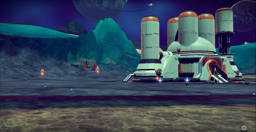
LIST OF FIGURES                                                                                                Master Thesis

  A.1   Animal Species Catalogue       .   .   .   .   .   .   .   .   .   .   .   .   .   .   .   .   .   .   .   .   .   .   .   .   48
  A.1   Animal Species Catalogue       .   .   .   .   .   .   .   .   .   .   .   .   .   .   .   .   .   .   .   .   .   .   .   .   49
  A.2   Seaweeds Catalogue . . . .     .   .   .   .   .   .   .   .   .   .   .   .   .   .   .   .   .   .   .   .   .   .   .   .   49
  A.3   Coral Stones Catalogue . .     .   .   .   .   .   .   .   .   .   .   .   .   .   .   .   .   .   .   .   .   .   .   .   .   50
  A.4   Sponges Catalogue . . . .      .   .   .   .   .   .   .   .   .   .   .   .   .   .   .   .   .   .   .   .   .   .   .   .   50
  A.5   Shells Catalogue . . . . . .   .   .   .   .   .   .   .   .   .   .   .   .   .   .   .   .   .   .   .   .   .   .   .   .   50
  A.6   Rocks Catalogue . . . . .      .   .   .   .   .   .   .   .   .   .   .   .   .   .   .   .   .   .   .   .   .   .   .   .   51

                                                   4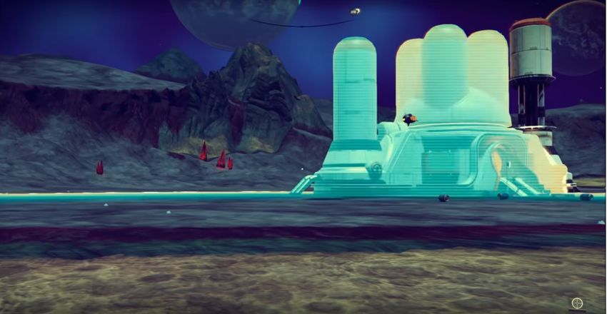
Chapter 1

Introduction

The underwater environments has about 90 percent of the living space on the planet,
and yet most of it remains unknown. The marine life is composed by plants, animals
and other organism who live in the oceans creating a whole ecosystem.
   The average depth of the oceans is about 3500 meters, but it can reach deeper.
The Mariana Trench[1], located in the Pacific Ocean, near the Mariana Islands is
the deepest trench on the Earth reaching 10984 meters deep. The light attenuation,
the water pressure and the temperature make the development and evolution of life
very difficult in deep environments where the light cannot reach.
   The propagation of light in water is controlled by reflection, absorption and back
scattering, which is described by the radiative transfer equation [2]. This behavior
makes that around the 3000 meters depth the light almost completely disappear.
In these environments the animals cannot rely in the sense of sight, so they have
evolved to be able to use other senses as the sense of hearing in order to see.

          Figure 1.1: Underwater environment scheme. Image source [3].

    Unlike the light, the sound travels much further in underwater than in the air.
These sounds travel kilometers before being attenuated and they produce strong
echoes due to the low attenuation and the collisions with underwater surfaces that
reflect the sounds. These sounds are presented in a large range of frequencies between

                                          5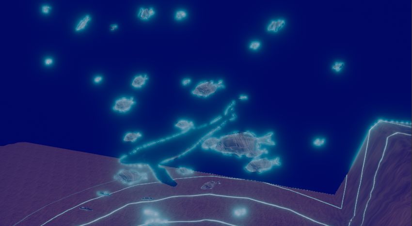
1.1. MOTIVATION                                                       Master Thesis

1 and 100000Hz, where we can found different type of sounds[4]. For example in
the frequency range of 20-500Hz we can found ambient noise produced by distant
shipping. There exist sounds above 100000Hz, called thermal noise which are the
minimum sound level that can be measured, generated by the Brownian motion of
the water molecules.
    The ocean is filled with sounds. These sounds can come from natural sources as
animals, waves movements, or it can come from human sources as ships or radars.
In the figure 1.1 we can see an scheme of the underwater environment with the light
represented as shades of blue, and different sources of sounds either animals sources
as the sperm whale, or human sources as ships.
    The ability to hearing is really important for a lot of animals, through it they
can perceive their surroundings, communicate and hunt. As said before, the animals
who live in deeper environments, usually have their hearing sense evolved in a way
that they do not depend of the sight. One example of this is the called echolocation
ability used by the sperm whales to hunt [5]. These whales emit a series of click
sounds that bounce on the preys and get back to themselves. The sound returning
to whale is called backscatter, and by analyzing it they can extract the essential
information about the prey such as size, position and others. This system is not
only used by some animals, even the humans use it, and you may know it as Sonar.

        Figure 1.2: Sonar System used by killer whales. Image source [6].

   These natural sounds are not anymore the only ones in the oceans, as the humans
have been evolving there are more ships, industries, and others producing sounds
that travel kilometers around interfering with the natural ones. And this does not
only applies to the surface level sounds, it also applies to the sounds placed at the
bottom of the oceans where they can reach deeper zones. These interference and
noises created by humans are known as noise pollution in underwater environments,
and it affects to all underwater ecosystem.

1.1     Motivation

Knowing the importance of the sounds in the water life, and the effects that can
produce the noise pollution in the oceans, the UPC have decided to participate in

                                         6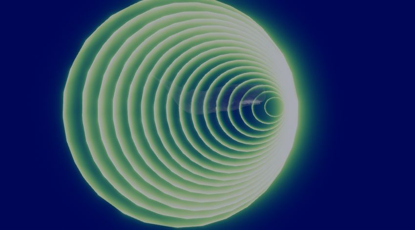
1.2. OBJECTIVES                                                        Master Thesis

the SONAR[7] event to raise awareness about the noise pollution in underwater
environments among young and international audiences.
    In order to do this there will be three main communication events: Paper pre-
sentations, 360’ Dome video and a Virtual Reality application. The three of them
will focus on the sound world under the sea, presenting it as a rich and a beautiful
world, with a lot of different sounds.

                        Figure 1.3: BIOSONAR 360’ Dome.

   In this work we will focus on the creation of the Virtual Reality application
that will provide the players the experience of being underwater and see though
the sounds. The players will understand how the noise pollution is affecting the
underwater life through this interactive experience where they sight will be distorted
by different human sound sources.

1.2     Objectives

The aim of this work is to create a Virtual Reality Serious Game based on an
underwater environment where the players can live the experience of seeing through
sounds. In order to achieve this experience we will create an underwater environment
where the player can move freely, and reach deeper zones where the light can not
reach, and sound waves are necessary to discover and interact with the environment.
   The objective of the players will be to reach the deeper zones while following a
path. During this journey they will explore a rich and beautiful environment filled
with different animals moving around, and sounds of all kinds. The main gameplay
mechanic will allow the players to emit animal sound waves, during their paths. At

                                          7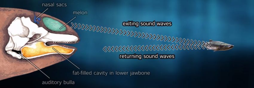
1.3. WORK SCOPE                                                         Master Thesis

the deeper zones these waves sounds will be the key to discover their surroundings
and illuminate the path.
    This experience will not be beautiful as it seems because the players will experi-
ence distortions in their sight each time a human sound reach them. This will most
likely make the players stop until the disorientation pass to be able to continue their
path. With these mechanic we want to raise awareness about the noise pollution in
underwater environments making the players feel the effect caused by the human
noises on the animals.

1.3      Work Scope

The purpose of this work is to raise awareness about the noise pollution in under-
water environments produced by humans. The fact that we are trying to represent
sound waves in a Virtual environment which is essentially visual, it is contradictory.
But, this is exactly the challenge of this work. We will represent the sound waves as
light waves trying to simulate the behavior that sound waves have for the animals.
The interference between animal sounds and human sounds will produce a distortion
in the waves causing effects in the communication and hunting of these animals.
   The duration of the application will be around 5 minutes in order to be a short
experience which a lot of people can play during the SONAR event.
    In the future, zones could be established where navigation was prohibited, cre-
ating zones of free contamination where animals could live without the interference
produced by humans.

                                          8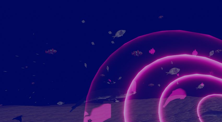
Chapter 2

State of the art

In this section we will focus on the use of sound waves and the creation of underwater
environments in games or related applications.

2.1      Sound Waves

The usage of sound waves or even electromagnetic waves as a visual effect is a
common practice in video games. The function of these kind of waves and its visual
effect depends on the gameplay mechanic intended to reproduce in each game. Here
we will focus on the ones related with ours.
    Radars are a common feature in games, these can be represented in different
ways. They can be useful to identify things that can not be seen in the player view,
these then can appear in a mini map mark with some symbol related to the object
found or the place, or it can enhance the player view in order to be able to see behind
solid objects, or hidden objects that can only be seen using this kind of mechanic.
    One good example of this is the Topographic Scanner from the game No Man’s
Sky(Hello Games, 2016)[8]. The main feature of this radar is to help the player to
discover the planet features by enhancing the player view highlighting and identify-
ing essential resources which the player can benefit from.
    The scanner is represented as a fast-moving wave that travels across the planet
surface over an specific radius while searching for essential resources highlighting
them. Each highlighted resource displays an icon identifying the type and over
hover it also show the distance between the player and the resource. Both effects
can be visualized in the figure 2.1, where in the first image (2.1a) we can see clearly
the wave represented with a blueish color in the surface of the planet and over the
surface of the main building, and in the second image (2.1b) we can see the wave
further away and the icon already displayed over the main resources found.
  As this is a mechanic from a game it also includes features as cool down or
maximum radius that can be improved with upgrades.
   Another example of the usage of waves more focused in 3D waves is the function

                                          9
2.1. SOUND WAVES Master Thesis
(a) Scanning function. (b) Highlighted resources.
Figure 2.1: No Man’s Sky Topographic Scanner.
of enhance the vision behind walls or opaque objects that do not allow the player to
see behind them. In this case we will use as example the Sonic Arrow ability from
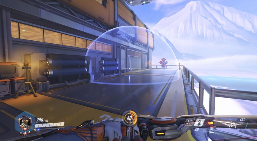
Hanzo character in the game Overwatch(Blizzard, 2016)[9].
This time the radar, as said before, allows the player to see other player be-
hind structures opaque such as walls, houses and other. The ability is triggered by
shooting an arrow. When the arrow collides with a surface it displays an spherical
3D wave which increases with time over a maximum radius highlighting the enemy
players inside that radius and making them visible for the other team even though
the are separate by some structure.
The effect of this ability can be seen in the figure 2.2. This time the radar effect
does not travel trough a surface, it increases with the radius sphere as it can be seen
in the figure 2.2a, and the radar does not focus on the objects this time, it only
highlights the enemy player making them visible as in the figure 2.2b.
(a) Spherical 3D wave. (b) Highlighted enemy player.
Figure 2.2: Sonic Arrow Hanzo ability.
As the previous example this ability has other features as damage and cool down
that we are not going to talk about.
We have talked about this two examples as both have some of the properties
that we will focus on when creating our radar wave feature. But there is plenty of
more in the game industry each of one unique and with a different functionality.
102.2. UNDERWATER ENVIRONMENTS Master Thesis
2.2 Underwater Environments
The use of underwater environments is common in video games. At the start these
used to be just levels or tiny parts of the game with no much interaction with
the rest, but as the industry has been evolving, almost every game which includes
water as rivers, ocean, lakes or similar the player has the ability to explore the
area beyond the surface. Meaning that the use of underwater environments is used
more frequently, furthermore there are games that have huge amount of underwater
environments as Subnautica(Unknown Worlds Entertainment, 2014), which we will
use it as example later. In this section we will discuss about the most common
techniques used in games to recreate that type of environment.
While creating an underwater environment the most important thing is to make
the player feel like if the character was inside water. This is even more difficult in a
virtual environment because the player knows that he is not in water environment
and due to the water resistance to our movements it is difficult to feel like as moving
in the water.
There are several things to take into account when creating underwater environ-
ments. We will focus on the the visible and sound elements that can enhance the
felling of being underwater.
(a) Underwater scene near the surface. (b) Underwater scene deep down the bottom.
Figure 2.3: Subnautica underwater scenes.
One of the most important thing is the environment color. To recreate a color
for the water, is common to use what is called a Fog effect. This effect consist in
the creation of a fog that is more dense with the depth, the color is usually used as
a variable to allow the creators to be able to create different environments using the
same effect. The most used color in the case of water is a color between blue and
green, but this kind of effect can be also used in other scenarios where the player
is inside of a fluid. One example could be a poisonous area in a game represented
with a purple fog. As the color, it is usual to use the density of the fog as a variable
also to be able to create different scenarios, it could even be constant, but when
representing underwater environment is it common to use a density that increases
with the depth.
The lighting is also an important element, to represent deeper scenes a darker
fog and the absence of light are common features used to identify the player depth.
112.2. UNDERWATER ENVIRONMENTS Master Thesis
As for the scenes near the surface the presence of light is needed and usually comes
with caustic effects in the terrain. This difference is clear observing the two differ-
ent scenes represented in the figure 2.3, which represent two different underwater
environments from the game Subnautica.
In addition to these effects it is important to add characteristic features of the
underwater environment such as vegetation, terrains and animals.
Sound is also used to enhance even more the feel of being underwater of the
player. It is common to use of bubble sounds in addition to some water moving
sound to recreate this kind of effect, but it can be improved with animals sounds
either movement sounds or call sounds.
Figure 2.4: Star Wars: The Fallen Order underwater environment scene.
Another important aspect of the creation of underwater environment is the move-
ment of the player. In most games it is imperative to create swim and dive anima-
tions to make the player feel like if the character was swimming underwater. These
animations combined with the elements mentioned before are the key to create a
feeling that the character is underwater. In the Figure 2.4 we can see an scene from
the game Star Wars: The Fallen Order (Electronic Arts, 2019)[10], where the main
character is swimming in an underwater environment, and we can identify the main
element discussed before as the fog, the vegetation and the animation.
A useful solution used in virtual environments is the use of haptics to enhance
the feel of the player and create an artificial feeling that he/she is in an underwater
environment. But as this is not in the scope of our project, so we will not focus on
these techniques.
12Chapter 3
Methodology
Our applications have been developed using Unity 2019.2.5f. The project uses the
Lightweight Render Pipline or LWRP[11], which provide us a performance optimiza-
tion by making some trade-offs with regard to lighting and shading. The usage of
a LWRP is a perfect fit for applications which run on lower end hardware, AR ap-
plications or VR applications as ours. It also includes the Shader Graph tool which
allows the user to create shaders without the necessity of coding, we will talk about
this in section 4.2 where we will discuss the creation of our sound wave.
The LWRP is one of the Render Pipipelines that introduces the concept of Script-
able Render Piplines, which give the developers more control, customization and
choice over the rendering processes. We have used this tools in order to create the
underwater effects desired, which we will talk about in the section 4.1. It is impor-
tant to know that our project uses a Single Pass Stereo Rendering mode[12] in order
to render the scene and effects correctly in VR, meaning that we have kept this in
mind when developing the shaders for the desired effects, this is further developed
in the section 4.3.
The headset used for the VR visualization is the HTC Vive. It includes a head-
mounted display, two wireless tracked controllers and two lighthouses. This set allow
the player to move freely in a pre-built room of 4x4 meters, in our case the player
movement is designed through the controllers, so the player will not walk inside this
room.
In order to develop our application using this set we have used the SteamVR
asset provided in Unity. This asset provides a CameraRig with the camera and two
controllers already linked with the HTC Vive HMD and controllers, and it provides
an easy way to us to develop gameplay mechanics using them.
133.1. LIMITATIONS Master Thesis
Figure 3.1: HTC Vive Hardware. Image source [13].
3.1 Limitations
In this section we will discuss the limitations either of the creation of the project
and the application itself.
As creating an underwater scene is not an easy task, that also requires a lot of
time, we have used already created 3D models in order to add life in our scene.
All the environment of our scene is not created by us, meaning that the different
animals included the animations, rocks, seaweeds and others have been acquired
from free web pages, where authors can upload their work and make it available for
other people or the Asset Store from Unity.
The 3D models used for the animals have been downloaded from Sketchfab[14],
a community where people can freely update their work and make it available for
other people to download freely or by paying a certain amount. For the rocks and
seaweeds, as we needed different kinds and models we have used Unity assets. For
the rocks we have used two assets: Free Rocks[15], and Rocks and Boulders 2 [16],
with these we have enough rock prefabs to decorate our environment avoiding usage
of the same rock prefab. For the seaweeds we have used the Yughues Underwater
Plants asset[17], which contains 109 prefabs including coral stones, seaweeds, corals,
shells and sponges. All of these models has allowed us to create a realistic underwater
scene with its own ecosystem containing different kind of animals and plants. In the
Appendix A you can find a catalogue of the different animals, plants and rocks used
to create the scene.
The sounds used for the animal sound waves, and humans sounds are extracted
from free sound web pages[18],[19],[20]. Our first intention was to use sounds pro-
vided by researchers, but these sounds always come with noise, which made them
not suitable for our application. The sounds used are still real animal sounds, but
143.1. LIMITATIONS Master Thesis
have been cleaned and prepared for usage in applications.
In order to run the application it is necessary to have a hardware which supports
compatibility with VR games. The recommended specifications are: GeForce GTX
970, Intel Core i5 4590, 8GB of RAM and Windows 10.
15Chapter 4
Description of the Application
In this chapter we talk about the development of our Serious Game and its features.
We have divided these in four sections: Environment, Sound Waves, VR Shaders
Implementation, and Gameplay.
First of all we start talking about the construction of the environment. Here we
discuss the different effects that we have implemented in order to create the feeling
to be underwater. We also define the behavior of the animals and how they move
around our environment.
In the section Sound Waves we discuss how we have created the sound waves in
a way that the player can see and hear them, and how the distortion of the human
sounds affect these and the player view.
Once we have introduced environment creation and the waves behavior, we com-
ment some modifications that we have done to some of the previous work in order
to adjust our project to Virtual Reality.
Finally to finish this chapter we describe the main gameplay of our Serious Game.
Here we define the main objective of the players, and the different activities that
they can do it while completing this objective.
4.1 Environment
Immersion is one of the most important aspects in a VR application. We have devel-
oped our environment to give the players the maximum feeling of being underwater.
To do this, we have implemented two effects: a Fog Effect, and an Underwater Dis-
tortion Effect. And we have populated the environment with seaweeds, plants and
animals to represent the underwater ecosystem.
In the figure 4.1 we can see our scene without any effect, animal or plant, just
the initial terrain. As we move through the chapter we are going to add elements,
and at the end, we will achieve a final picture of our created environment.
164.1. ENVIRONMENT Master Thesis
Figure 4.1: Scene without effects, animals or seaweeds.
4.1.1 Fog Effect & Lighting
In the section 2.2, we have talked about the different techniques used to represent
the underwater environment color, specifically the called Fog Effect. Here we will
see how we have implemented it. We will talk about the lighting in the scene, which
combined with our fog effect, has allowed us to achieve the desired lighting in the
environment.
The usage of an LWRP project has allowed us to use the Post-Processing[21]
process to apply full-screen filters and effects to our camera. Both of the used
effects are created as custom effects, which each one needs a C# script to create
and modify the effect, and an HLSL file with the shader containing the effect. Once
created, these effects appears in the Post-Processing Volume with the default effects,
where you can modify the effects to achieve a final effect applied to the camera. First
we will talk about the effect, and then we will see how it is implemented as a Custom
Post-Processing Effect.
Our implementation of the Fog Effect is based on the implementation done by
PeerPlay[22]. The main purpose of the Fog Effect shader is to create a fog which its
density increases with the depth. This fog represents the color and density of the
underwater environment.
The first thing needed in our shader is a depth value to know the distance
between the object and the camera, for this we have used the build-in shader variable
called CameraDepthTexture. This variable contains the depth data of our scene
inside a texture, and it is generated automatically, so we do not need to do extra
computations to extract it. It is important to activate the DepthTextureMode of the
camera via script, otherwise this texture will not be generated. Using this variable
and the screen UV coordinates we are able to extract a float representing the depth.
174.1. ENVIRONMENT Master Thesis
The computed depth float rendered in our screen would give us an scene in grey
scale, where the closest objects would be dark and the further ones white. But, as
we wanted to be able to change the fog color, we have used a variable to change it.
To implement this color we only need to multiply our computed depth value by this
color. In our case as we are representing a real underwater scene not too close to
the surface we have selected a shade of dark blue. It can be seen in the figure 4.2,
where the effect is visible.
Finally now that we have our desired fog color, we also needed to combine it with
the actual rendered scene. In order to do this, we have used a linear interpolation
between the output extracted before, and the output of a texture lookup using the
build-in shader variable called MainTex, and the screen position as coordinates,
using the depth value computed before as the interpolation parameter.
Using this we get an scene where as the depth increases, the fog is more intense.
To get more freedom with the fog we also have implemented two variables that allow
us to determine the the distance where the fog starts, and the maximum distance
where the fog is completely dense. With these two variable we can change the
behavior of the fog and get the one desired.
Figure 4.2: Scene with fog effect added.
In the figure 4.2 we can see how the scene represented in the figure 4.1 has
changed only adding the fog effect. Now the scene starts to seem like an underwa-
ter environment, but it still lack of a lots of components, which we will introduce
progressively.
The Fog effect shader still needs some extra modifications in order to ensure
that works in VR. We will talk about this in the section 4.3 together with the other
shaders.
Now that we have our shader created, we will talk about the creation of the
Post-Process effect script that allows us to add the Fog effect in the Post-Process
184.1. ENVIRONMENT Master Thesis
Volume asset and modify it directly in our scene. It is important to know that we
do not need to modify the code base or the other effects in order to implement a
new one.
A custom Post-Processing effect script[23] is divided in two classes: Settings and
Renderer. Without one of this two the effect does not work, and they must be
linked.
The Settings class is a class that allows us to store the shader data of our ef-
fect. This class needs to inherit from PostProcessEffectsSettings and need to be
serializable. We also need to specify the renderer class which is linked to using the
PostProcess() key word, the injection point for the effect and the shader associated.
In our case, the injection point that we use is AfterStack, as we want to apply the
effect after the builtin stack and before FXAA(Fast Approximate Anti-Aliasing).
Finally as we want the effect to be visible in the scene as we modify it we use the
key word ImageEffectAllowedInSceneView. In the figure 4.3 we can see our Fog
effect Settings class.
Figure 4.3: Fog Effect Settings class.
The Renderer class contains the rendering logic part. This class needs to inherit
from PostProcessEffectsRenderer, being T the settings class attached to the
renderer. In our case the only thing that this class does is to render the effect in
the Render() function.
On top of the fog effect we have added some lighting effects to improve the
realism of our underwater environment. Our objective is to represent the lighting
that we have seen in the figure 1.1, where the light decreases with the depth, and in
the deeper zones there is no light.
As our game represents directly the underwater environment, we do not use any
Skybox or Sun source, we only use the Ambient color as light source. In order to
represent the decrease of the light in our scene, what we have done is to interpolate
the Ambient Color between the initial color and a completely black color using the
height of the camera as the interpolation parameter.
This effect is not enough to get an environment completely dark where the players
cannot see the terrain or their surroundings, our problem is that the environment
color is determined by the fog. So we have applied the same technique as before, we
interpolate the fog color between the initial one, which is a bluish tone, and a black
one using the same interpolation parameter as before.
194.1. ENVIRONMENT Master Thesis
With this two light changes, we finally get a completely dark scene in the deeper
zones of our environment. In this zones the players will have to use their own
sound waves, or the sound waves of the surrounding animals in order to discover the
environment.
But, in order to not have the deeper environment completely dark we have added
some sources of light, the effect of this light is minimum and it does not illuminate
enough to avoid the player the use of the sound waves to discover their surroundings.
These sources of light comes from different animals that shine in the dark. In our
case we have used different kinds of jellyfish and squids.
(a) (b)
Figure 4.4: Underwater scenes in the deeper zones of the environment.
In the figure 4.4a and 4.4b we can see the environment in the deeper zones. Here
the player only sees the light coming from this animals, but their surroundings are
still dark enough to not see what there is around.
We have said that there is a light source coming from the animals, but light
sources are expensive, and our performance will be affected if we use a lot of them. So
in order to not use any kind of light source, what we have done is to use the Emission
Map of the materials used in this animals. Increasing the color and intensity of the
Emission Map we achieve an effect similar to the one achieved using light sources
without affecting the performance.
It is important to know that these jellyfish do no move as the other fishes, which
we will explain their movement in the section 4.1.4. We have implemented a simple
movement for the jellyfish, which consist of a linear movement up and down with
low speed. This is not applied to the squids, they have the same movement as the
other fishes.
4.1.2 Underwater Distortion Effect
Our Underwater distortion effect tries to represent the visual distortion created by
the movement of the water. As the previous effect, this is also created as a Custom
Post-Processing Effect, so it is divided in two files as before: the HLSL shader, and
the C# script. In this case we will focus only in the shader, as the creation of
the C# custom effect script is the same as before changing the data from this new
204.1. ENVIRONMENT Master Thesis
shader. Our implementation is also based in the implementation of PeerPlay[22] as
the Fog Effect, and as the same way as before, we have needed to implement some
characteristic modifications to the shader in order to adjust it to VR, specifically to
Single Stereo Pass Rendering, these modifications, as said before, will be discussed
in the section 4.3.
The main purpose of our shader is to distort the pixels of the camera based on
Simplex Noise[24]. The Simplex Noise function give us a value between −1 and 1
for each pixel, we use this value to create a directional vector changing the value
to a range between 0 and 1, and finally we shift the position each pixel using the
directional vector created.
The Underwater Distortion Effect is controlled by four parameters: Noise Scale,
Noise Frequency, Noise Speed and Pixel Offset. There is also two more parameters
that we will talk about it later, but this ones do not effect directly to the distortion.
The Noise Scale parameter allows us to scale the noise effect changing the range
of the output float. The Noise Frequency allows us to control how the noise change,
as we increase this value the noise will change more. In the figure 4.5 we can see
an example of this, where the noise increase starting low in the figure 4.5(a), and
having a high value in figure 4.5(c). As we increase the frequency, the noise values
change more, and it becomes less uniform around the pixel.
(a) Frequency = 1.0 (b) Frequency = 10.0
(c) Frequency = 20.0
Figure 4.5: Noise changing with the frequency.
The Noise Speed parameter allows us to modify the speed at which the noise
changes. As this parameter increases more will change the distortions with the same
amount of time. And finally, the Pixel Offset is used to change the offset of the pixel
produced by the noise.
To create the directional vector we have used the cosines and sinus of the noise,
which results in a 2D vector, which normalized becomes between 0 and 1. Finally we
use the build-in shader variable MainTex to shift the pixels using this directional
vector and our Pixel Offset variable.
214.1. ENVIRONMENT Master Thesis
To create a more realistic effect, we have applied a similar depth effect than
the one applied in the Fog Effect, but with opposite result. This time what we
have done, is to apply more distortion as the object is near the player. To do this,
we have computed a float depth value as before, and using two parameters which
indicate the minimum distance and the maximum distance, we have distorted the
scene depending on the distance with the camera.
(a) (b)
Figure 4.6: Two Underwater scenes applying the Underwater Distortion Effect.
In the figure 4.6, we can see the same scene with the Underwater Distortion
effect applied in a different way. In the figure 4.6a we can see less the effect, but is
still noticeable in the rock because it is near the player. Instead, in the figure 4.6b
we can see perfectly the effect and as we have increased the maximum distance, the
effect is also noticeable in the further terrain. Our scene have a similar effect than
the one represented in the figure 4.6a.
The effect created with this shader represents the motion of the water and the
visual distortion created in a realistic way, but it has a problem. This effect causes
a visual distortion on the player and our application is a VR application, so can
cause Motion Sickness to the player. As we will comment later in the sections 4.2.1
and 4.4, it is important to not disorientate the player a lot, because this can cause
Motion Sickness and make the player not able to enjoy the application. For this we
have decided to apply a low values in this effect making the effect visible but not
enough to cause Motion Sickness.
It is important to know that we must apply the Fog Effect before the Underwater
Distortion Effect, otherwise the effects will not work properly and we will get strange
results.
4.1.3 Scene Design
Now that we have explained the two effects used for the creation of the underwater
environment, we will briefly discuss the scene design.
In the last figures we have seen how the environment has evolved using the
two effects, now the scene has the appearance of an underwater environment, but
it still lacks of an ecosystem of animals and plants, and also rocks filling to be
224.1. ENVIRONMENT Master Thesis
a realistic underwater environment. In this subsection we will focus on the scene
design, meaning on how we have distributed the plants and rocks, which of them
have we used and why.
As said in the section 3.1, for both the plants and rocks models we have used
assets from the Unity Asset Store. For the plants we have a complete selection of
shells, corals, seaweeds and sponges. And, for the rocks we have a selections of
different rocks with different shape and size. All of these has allowed us to create
an scene with a large diversity of plants and rocks.
It is important to know that the majority of this assets, especially the plants,
have a LOD system included. With the LOD system, these models change the
number of triangles with the distance of the camera, and even get culled. This
has allowed us to use more of these models in the scene creation because at long
distances the performance will not be affected.
For the distribution of these plants and rocks we have distributed them using
the different levels on the terrain. Our terrain is composed by four levels of depth,
with the last one being the one with more depth difference with the others, having
a difference of depth with the third level at least twice the difference between the
other levels. This makes the last terrain level the deepest one, and at the same time
the one without any kind of light reaching the surface of that level. We also have to
add, that this level is the largest one to make the player discover all the environment
in here using the sound waves. In the figure 4.7 we can see the terrain visualized
from far away with the different levels. The white cube is the player start point.
Figure 4.7: Scene terrain visualized from far away.
In the upper levels we have created a zone with a lot of colorful plants and corals
of different kinds. Also we have added some small and medium size rocks, but in
these levels we did not wanted a rocky level. As we go down the number of plants
decreases, and the plants begin to be smaller and with less vivid colors. In the last
level we rarely can find plants, and the ones we can find are small ones. This level
is filled with coral stones, rocks and shells. As we have a large level there is rocks
of all the sizes.
234.1. ENVIRONMENT Master Thesis
(a)
(b)
Figure 4.8: First level(a), and deepest level(b) of the terrain in the scene.
In the figure 4.8, we can see the difference between the first level of the scene
where the terrain is filled with different plants, corals and shells, and the deepest
level where we can see bigger rocks, a few small plants and a lot of coral stones. For
the sake of making a good comparison we have used the same light characteristics,
in game the deepest level is completely dark, and we cannot see the level with the
same detail as the first ones.
244.1. ENVIRONMENT Master Thesis
4.1.4 Boids
In all underwater environments there is an ecosystem with different animals and
plants, without which the environment feels empty. We have created our own ecosys-
tem with different types of fish and mammals, this helps to enhance the feeling of
being underwater and at the same time, it is used to add more animals that emit
sounds as the main player does.
The presence of animals in the environment enhance the feeling of being under-
water. But, as we have developed a Virtual Reality application the feeling produced
is even greater than in a non-VR application or game. In VR the players sees the
fishes swimming around as if they could even touch them, which is not possible in
a non-VR application.
The movement of these animals cannot be represented by some lineal movement
or a movement that does not take into account their surroundings, which made us
implement a behavior based on the flock behaviors defined by Craig W.Reynolds[25],
and the Boids implementation of Sebastian Lague[26].
Our implementation simulates each animal as an individual particle, making all
the simulation as a particle system simulation. Even if we define each animal as one
particle, the motion of each one is defined by their surroundings, meaning that the
motion of an animal is defined by its nearest neighbours. This simulation is based
on four individual behaviors:
1. Separation Behavior.
2. Alignment Behavior.
3. Cohesion Behavior.
4. Environment Collision Behavior.
Combining all of these four behavior we are capable of simulating a natural
motion of the animals in the underwater environment. To achieve an even further
realistic motion we have implemented a fifth behavior called: Predator Behavior.
We will talk about it later in this section. There is also a sixth behavior that is used
as a Gameplay, here we will only mention it, and in the section 4.4 we are going to
describe it in detail.
Before we discuss the behaviors in detail, we need to know how the code is struc-
tured and the reason behind it. The simulation of these behaviors is the bottleneck
of our application, and we have been careful in order to create an environment full
of animals, and still have enough performance to be able to run the application
smoothly in VR. In the figure 4.9 we can see an scheme of our implementation.
Our implementation has three main scripts: Boids Manager, Boid Agent and
Behaviors, one Scriptable Object: Agent Settings, and one Compute Shader: Near-
estNeighbours.
The Boids Manager is in charge of performing the simulation and joining all
the elements together. We only have one instance that simulates the motion of all
254.1. ENVIRONMENT Master Thesis
Figure 4.9: Boids structure scheme.
animals. Instead, each animal has a BoidAgent script and Behaviors script. The
BoidAgent script is the one that updates every frame the position and velocity of
each agent based on the behaviors defined in the Behaviors script. This partition
has been made in order to reuse the Behaviors script when we create the Predators,
about which we will talk later in this section.
The Agent Settings is an Scriptable object, and it contains all the data of the
agents, meaning that all the agents will have the same constants and weights use
to compute the behaviors. It is done in this way in order to avoid the repetition of
constants in each agent. Our settings contains 15 float constants, meaning that we
have 15 ∗ 4bytes = 60 bytes of data, that is almost nothing, but our system is made
by hundreds of agents so as we increase the numbers of agents these data will also
increase resulting in a big chunk of unnecessary data.
Finally the NearestNeighbours is a Compute Shader. The Compute shaders are
programs that run on the graphic card allowing us to use parallel programming. As
it is said in the name, here we compute the nearest neighbours for each agent, and
at the same time the different data that we need to compute the behaviors. This is
done in parallel as we need to compute the neighbours of each agent each frame by
traversing all the other agents and computing the distance between them. This is a
lot of computation time, and our Compute shader allows us to have one thread for
each agent, making the computation of all agents at the same time. It is important
to know that here we do not write or change any data of the agents making possible
the parallelization.
Now that we have defined the structure and how the code works, we will discuss
in detail about the different behaviors that an agent has. Each of the behaviors is
independent of the others, and most of them use data extracted from the Nearest-
Neighbours compute shader in order to save computation time. The sum of all of
them is used to compute the new velocity of the agent, and thus the new position.
The Separation Behavior steer away the agents between them. This is necessary
as the next two behaviors tend to bring the agents together. To calculate this force
we use a vector in the opposite direction of the sum of all difference between the
position of the agent and the ones surrounding it divided by the number of agents.
264.1. ENVIRONMENT Master Thesis
We have defined a radius called avoidRadius, which define a sphere of that radius
which every other agent inside is taken into account to compute this force.
Both of the Cohesion Behavior and Alignment Behaviors use another radius
called viewRadius, which as before the agents inside it contribute to each force. The
Alignment Behaviors makes the agent to steer to move in the same direction of
the nearby agents, meaning that aligns the velocities of surrounding agents, making
them behave as a flock. In this case we use a similar vector than before, but this
time we sum all the directions of the neighbours inside the view radius, and divide
it by the number of neighbours. In the case there is no neighbours we do not modify
the forward velocity. In the figure 4.10 we can see how the fishes in a flock are
almost totally aligned.
Figure 4.10: Fishes in a flock aligned.
The Cohesion Behavior makes the agent to steer towards the center of the nearby
flock-mates. In this case we use the same radius as before to compute center of the
flock, and use the difference between this center and the agent position to compute
this force.
The last of the four main behaviors is a little bit different, the main objective is
to make the agent avoid environment obstacles. The first thing we have to do is to
check if there is an obstacle or not in the direction of the agent, so we cast a ray in
the forward direction. In the case that an obstacle exists, we cast rays uniformly in
a sphere[27], and check for a new direction were the agent can move freely. In the
figure 4.11 we can see in action a flock of fishes avoiding the obstacles while moving
together.
In the figure 4.12 we can see how the points of the sphere are created. In the
case of the image there are 1000 points, and in our case we use 300 points because
it is enough for the agent to find a new path. We also have to mention that the
274.1. ENVIRONMENT Master Thesis
Figure 4.11: Flock of fishes avoiding obstacles.
creation of the directions has his own static class, and is not a part of the Boids
structure because this could be reused in case we need it.
Figure 4.12: 1000 Uniformly distributed points in a sphere. Image extracted from
[27].
In order to differentiate the environment obstacles and the animals, we have
created a layer for them. This layer allows us to ignore all the colliders except the
obstacles ones, meaning that only the objects in the obstacles layer will contribute
to this fourth force because the ray casting will ignore all the others. Using this
284.1. ENVIRONMENT Master Thesis
we have also created a bounding box of all the terrain in order to maintain all the
animals in the desired area.
We have created further separations in this bounding box to make sure that all
the animals are distributed for all the space. Also this has allowed to separate some
species that live in deeper waters from the surface.
It is important to know that we have used weights in order to limit each one of
the behaviors we have talked about. This allows us to have different weights in each
one, to create the desired motion.
With all these four behaviors we get a natural movement of the animals in our
underwater environment. But, as we added new species in our environment this
structure began to fail. All of our animals where controlled by the same manager,
so every one of them had the same behaviors, meaning that each specie was exactly
the same, and behave the same way with their surrounding. The fishes swam around
sharks, or killer whales as they were not trying to hunt them. So to fix this in a easy
way without making the ecosystem too complex, we created the Predator class.
The main structure of the Predators system is exactly the same as the Boids
structure. It has his own manager, the Predator Agent script and it uses the same
Behavior script. The difference is the NearestNeighbour compute shader, the set-
tings and the behaviors used. As we said, this is the bottleneck of our application,
so in order to make things not too complex, what we have done is to make the
predator with only the four main behaviors and then introduce a fifth behavior in
the boid agents.
Figure 4.13: Fishes avoiding the killer whale.
The main function of the fifth behavior added in the boids agents is to steer the
agents in the opposite direction of the predators located in a sphere of a defined
radius called predator radius. To calculate this force an agent has to be aware of the
predators in his surroundings, to make this we have introduced a new calculation
294.1. ENVIRONMENT Master Thesis
on the compute shader where each agent computes the distance between itself and
the predators, and extract the ones inside the radius. Finally with the sum of the
positions difference, we can compute the new force.
This can be seen in the the figure 4.13, where the fishes nearby the killer whale
are steering their movement towards the opposite direction of the killer whale.
(a)
(b)
Figure 4.14: Final scenes with fishes swimming around.
This system could be even further improved. In our system only the boids agents
are aware of the predators, in a real system the predators will also be aware of their
prey, and follow it trying to hunt them. Also an extra behaviors could be developed,
and some differentiation between different animals could be done. An example of this
304.2. SOUND WAVES Master Thesis
extra behaviors could be: mammals going to the surface in order to breathe, creating
a more complex predator chain with more species and differentiation between them.
But as the focus in our application is to be able to run it in VR, and make the player
focus on the sounds, we decided not to improve it further.
4.2 Sound Waves
In this section we will talk about the sound waves. First of all, we will describe
about how we have created them; and later, we will discuss about how the animals
and the player emit these sound waves. Finally when we know all the sound waves
behaviour we will describe how the human sounds have been created and how they
distort the sounds produced by animals.
As said before, our main objective is to populate our scene with multiple sounds
to make the players feel as they were in a real underwater scene, where the animals
are constantly making sounds in order to communicate, hunt among others. At the
same time, we want these sounds to be visible to the players, and in the deeper parts
of the scene they have to be essential to help the players to locate themselves and
their surroundings.
This has been a difficult part since we are not used to see sounds, so we have
combined a representation of real sound waves with an artistic touch adding colors.
We have achieved this by making them shine in order to achieve a colorful world
even in the deeper scenes where the players are not able to see.
To create a single wave we have used an sphere with a shader that makes them
transparent except the outline, this implementation is based on the Brackeys imple-
mentation of a force field[28]. Unlike the shader created in the sections 4.1.1 and
4.1.2, this shader has been created using the Shader Graph Tool. This has allowed
us to create different materials changing the shader parameters to represent different
wave types. And, as the other shaders, we have also needed to adapt the shader to
the Single Pass Stereo Rendering mode, but we will discuss it in the section 4.3.
The shader is divided in two parts. The first one makes the intersection of the
sphere and the other objects glow, and the second part makes the outline of the
sphere glow.
In order to get the intersection between the sphere and the other objects we
have used the Screen Depth node which gives us the camera’s depth buffer, and
the Screen Position node which gives us the mesh vertices in screen position. By
subtracting the screen position alpha from the scene depth we get an intersection
effect which is represented by a fading gradient where the sphere intersects with
an object. We have introduced a variable called Offset, which allow us to control
this gradient by offsetting the screen position. As we decrease the Offset value the
intersection is more noticeable.
All of this has to be applied to the alpha PBR Node Master. In order to apply
this into the alpha color we need to reverse this color by using the One Minus node,
which subtracts the input value to 1. This is needed because we have black values
314.2. SOUND WAVES Master Thesis
in the intersections, and black values are transparent if applied into an alpha value.
We need also the values to be between 0 and 1 as we are working in alpha values.
To make the rest of the outline glow we have used a Fresnel Effect node. This
effect allows us to easily lighten the outline of our sphere just adding this node
output to our current alpha color. To control this effect we have added a variable
which allow us to determine the power of the Fresnel Effect.
On top all of these we have added a Transparency variable which makes all the
glowing effect more visible as we increase it, or less visible as we decrease it.
Finally in order to be able to represent different sound waves, and make them
attractive we have added an Emission variable, which determines the color of the
glowing effect and so the color of the sound wave.
Figure 4.15: Wave sound shader preview.
In the figure 4.15 we can see the preview of the shader effect obtained with the
Graph Shader Tool. Here we can see clearly a material transparent except the its
outline.
In contrast in the figure 4.16, we can see how the shader is applied to an sphere,
and how the sphere glows in the intersection of the rock and the terrain, and the
glow of the rest of the contour that does not intersect with something. Here we can
also see how we have increased the intensity of the Emission color in order to make
the wave more visible.
This sphere is the basis of our representation of sound waves, but by itself it is
not enough.. In order to represent the waves we have created an script to describe
the behavior of a single wave, and an object to spawn the waves in different ways.
As we can see in the figure 4.16, the prefab of our wave looks like this, an static
sphere with the glowing outline and intersection with other objects. Our objective
is to make this sphere to behave in a similar way to a real sound wave. To do this
we have applied two changes to the original prefab.
The first thing we have done is to increase the size of the sphere with the time.
In order to do this, we have defined a time step, which in each step increases a
324.2. SOUND WAVES Master Thesis
Figure 4.16: Single wave sound in the scene.
certain amount the radius of the sphere. When the radius exceed the maximum
radius defined, we destroy the object. With this we have simulated the propagation
of the wave through the environment.
In addition to this we have added a similar technique to decrease the alpha color
of the wave. At first the wave is very shiny, but as we know, as a sound wave
propagates through the environment it attenuates. To represent this attenuation,
we have used the alpha component of the color. As the wave radius increases it
also becomes more transparent, making it seems that the wave is fading away as it
propagates.
Also, we have added to this sphere the ability to track the position of the camera
and compute if the camera is inside or outside the wave. This is important because
if the camera is inside we need to apply a Back Face Culling rendering, otherwise
the player will not see the waves outline. In the case of the waves spawned by the
player we always know that the camera will be inside of the waves, so we directly
apply Back Face Culling to these waves.
The sphere model used is the one provided by Unity, we consider this model good
enough for our approximation. We tried to use other models with more triangles in
order to have a more accurate sphere, but these models reduced our performance
especially when applying the Back Face Culling as we need to traverse all the tri-
angles of the mesh. An at the end we decided that the sphere model provided by
Unity had enough triangles without affecting the application performance.
As said before, one of these waves is not enough to simulate sounds. For this we
have created an spawner class, which allow us to instantiate sound waves as desired.
These spawners are joined with the animals that emit sounds, and the main player.
The animal spawners and the player spawner have the same functionality, but with
a few differences.
33You can also read