2021 Cast in Steel Competition: Casting Thor's Hammer - Shelton Fowler, J. Chandler Liggett, Daniel Garcia
←
→
Page content transcription
If your browser does not render page correctly, please read the page content below
2021 Cast in Steel Competition: Casting Thor’s Hammer

 Shelton Fowler, J. Chandler Liggett, Daniel Garcia
 Faculty Advisor: Dr. Mingzhi Xu

 Partner Foundry: Carolina Metal Casting
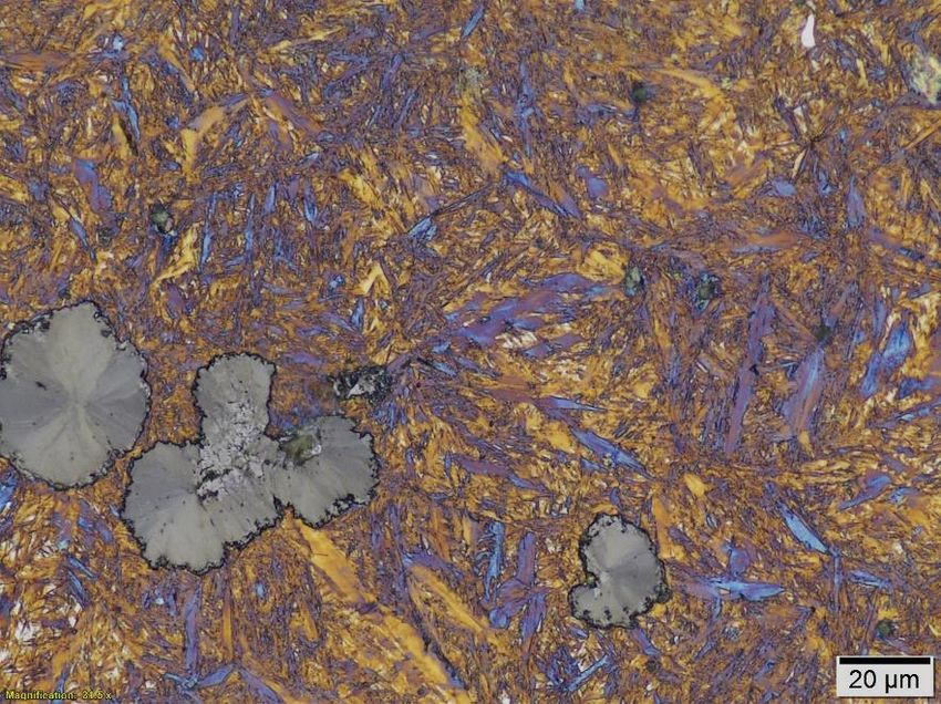
Table of Contents:

1. Introduction
 1.1 Introduction to Thor’s Hammer
 1.2 Introduction to Design Requirements
 1.3 Introduction to Bimetal Castings

2. Design and Development
 2.1 Designing Thor’s Hammer
 2.2 Lightweight Structure Design
 2.3 Alloy Selection and Bimetal Casting Design
 2.4 Hammer Structural Design

 2.5 Casting Process Selection and Design
 2.6 Gating and Riser Design
 2.7 Heat Treatment Design
3. Manufacturing Methods
 3.1 Additive Manufacturing of Patterns

 3.2 Investment Shell Production
 3.3 Sand Mold Production
 3.4 Casting Process
 3.5 Postprocessing
 3.6 Heat Treatment

 3.7 Final Preparation
4. Results and Discussion
 4.1 Final Alloy Composition
 4.2 Microstructure Analysis and the Bimetal Interface
 4.3 Analysis of Fusion Defects in the Hammer Casting
5. Conclusion
1. Introduction
1.1 Introduction to Thor’s Hammer

 Thor’s hammer, arguably the most iconic relic from Nordic mythology, continues today to be well
known as both a symbol of classic Nordic mythology and an icon from the popular Marvel comic
superhero. Thus, what makes a hammer a true “Thor’s Hammer” differs widely from individual to
individual based on their personal backgrounds. To one person, Thor’s Hammer may conjure images of
the classic Nordic symbol for Mjolnir, the name of Thor’s Hammer, while for others Thor’s Hammer is
always seen in the hand of Chris Hemsworth. Both depictions however have together carved a distinct
legacy behind Thor’s Hammer which have formed it into the icon which it is today.

 According to Nordic mythology, Thor’s Hammer was the weapon of the god of thunder, Thor. The
most notable property of the hammer was, when thrown, the hammer would always return to the hand
of Thor. [1] The hammer was Thor’s chief weapon and was used to defend Asgard and to defeat the
giants, or jötunn.[1] First and foremost, the hammer was a weapon of war, but it was also an instrument
of blessing according to Nordic culture. Several historical sources indicate that the hammer was used to
consecrate and to bless in formal ceremonies marking events such as marriage, birth, and death. [1]
What is unique mythologically about the hammer is that it was used as both an instrument of death and
of consecration. One famed historian refers to the Nordic idea of the separation between the sacred and
the profane. [1] [2] Thor’s hammer was used often to delineate the two, banishing the profane and
consecrating the sacred. Thus, according to Nordic mythology Thor’s Hammer was functionally a
weapon, but symbolically was so much more. It was both a weapon of war and an instrument of sacred
rites.

 The hammer is depicted symbolically as shown in Figure 1. A sketch of an actual historical Thor’s
Hammer amulet is shown here, recovered from an archaeological site in Sweden. Traditional Thor’s
hammer depictions show a prism like shape rather than the rectangular shape of today’s
sledgehammers. Thor’s Hammer in ancient tradition was depicted similarly to today’s club hammer,
with a raised center to carry the center of gravity forward along the hammer as shown in Figure 2.
Thor’s Hammer from historical findings and depictions is often intricately adorned with symbols and
references from Nordic mythology, each bearing their own meaning.
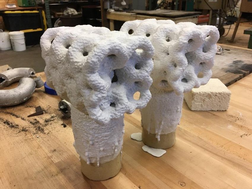
Figure 1: A Depiction of a Thor Hammer Pendant Uncovered in Öland, Sweden [1]

 Figure 2: Modern Club Hammer Resembling the Traditional Thor’s Hammer Shape [3]

 Although in the most classical sense Thor’s Hammer ought to be defined by its mythological roots,
Marvel comic books have over the years revolutionized and breathed new life into the character of Thor
and his famous hammer. The Marvel comic series and Marvel film universe depict Thor’s Hammer as
shown in Figure 3. The hammer is cuboidal, with a straight, seemingly cylindrical handle and leather
strap. The edges of the hammer face are beveled, with a perfectly flat face. Some engraving is visible on
the hammer, but not as much as on the mythological Thor’s Hammer symbol.
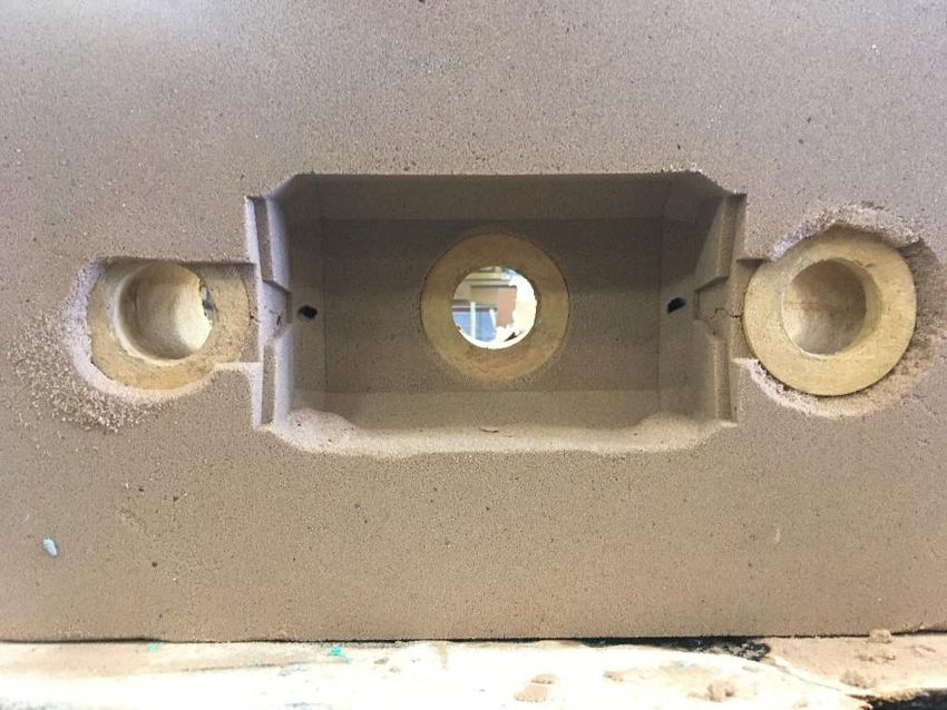
Figure 3: Marvel Comic’s Hammer of Thor Then and Now. [4] [5]

1.2 Introduction to Design Requirements

 In the 2021 Cast in Steel Competition, the Steel Founder’s Society of America put forward the
challenge to not only produce a steel Thor’s Hammer through the use metal casting techniques, but also
required the hammer to be fully functional. Furthermore, the hammer was required to weigh a
maximum of 6 lbs. and be under 20 inches long. This presents several engineering challenges and
requirements which must be considered when designing the casting.

 To develop a casting which not only encapsulates Thor’s iconic hammer, but is also fully functional,
several additional design factors must be considered. First and foremost, Thor’s hammer was his
weapon of choice and as such it should be fully functional as a weapon of war. The hammer should be
strong enough to withstand repeated impact through a variety of materials encountered in battle,
including wood, bone, and metal. As such, considerable toughness must be incorporated.
Simultaneously, it must be hard enough to resist excessive marring or deformation during use when
struck against other objects. For these reasons, the hammer must contain a balance between hardness
and toughness to be durable as a weapon.

 More than just its effectiveness as a weapon of war, Thor’s hammer was also seen as an instrument
of blessing in Nordic mythology, and for this reason there should be a sense of elegance and refinement
to the implement which goes beyond a mere instrument of war. Thor’s hammer should be elegant as
well as deadly.
Thus, the design requirements placed upon this product are as follows. First and foremost, the
hammer must be made of steel, be under 6 lbs total, and remain under 20 inches long. Second, the
hammer must feature a combination of good hardness and toughness to allow for its functionality as an
instrument of war. Thirdly, the implement must be aesthetically pleasing and fitting in its symbolic role
as an instrument of consecration.

1.3 Introduction to Bimetal Castings

 Selection of an alloy for casting applications is often a compromise between mutually exclusive
material properties. Applications requiring both high toughness and high hardness often lead to
significant compromises because high hardness is advantageous for wear resistance but can result in a
brittle material with low toughness. [6] For this reason, the possibility of choosing two alloys whose
combined strengths overcome their individual weaknesses is extremely beneficial. This is often
accomplished by welding or mechanical fastening; however, both processes add time and cost to the
manufacturing process. Recent work done in the field of metal casting has shown that two alloys may be
fused through the casting process to form a bimetallic composite featuring a strong, seamless
metallurgical bond.

 In research done in the area of metal casting for high wear applications, it is shown that cast iron
poured on monolithic or crushed steel wear plates offers significant potential for forming cost effective
wear components. According to a study performed by T. Wróbel, bimetal casting is an extremely
economical means of producing a casting with good surface properties when the interior properties of
the casting are unimportant. [7] Figure 4. shows a schematic reproduced from Wróbel’s work which
demonstrates the principle of bimetal casting, in which a surface alloy was selected for wear
performance or high hardness, while the interior of the casting was designed to meet a separate set of
criteria. [8]

 Figure 4: Design Schematic of a Bimetal Casting Reproduced from Work Published by T. Wróbel [8]
In further studies performed on bimetallic castings, it was shown that a bimetal hammer could be
cast for industrial crushing applications. This casting featured a crushing surface of high chromium white
iron for good wear resistance and a base of low carbon steel for high toughness. This was accomplished
by first pouring white iron and allowing it to partially solidify before following up with a second pour of
low carbon steel. Figure 5 shows the schematic of such a casting, complete with microstructure analysis
and a hardness gradient across the interface region. [9] This study shows the potential for implementing
bimetallic casting techniques in the development of a cast hammer for high impact applications.

 Figure 5: Bimetallic Hammer Cast for Crushing Applications [9]

 2. Design and Development

2.1 Designing Thor’s Hammer

 First, as previously discussed, Thor’s hammer features a large, almost oversized head and undersized
handle regardless of the overall form factor or specific design adopted. To cast a hammer which is
undeniably recognizable as Thor’s iconic hammer, the overall size and scale of the hammer cannot be
compromised. However, to keep the hammer under 6 lbs., significant design changes must be made.
Only three aspects of the hammer may be changed to reduce overall weight. Weight can be reduced by
changing the material, the size, or the shape of the casting. However, as the competition specifically
requires the hammer be made of steel, weight reduction through alloy change is limited. Although a
filler material or other alloys may be used in addition to steel, the core features making the structure a
hammer should be steel to be in accordance to the spirit of the competition. The size of the hammer can
arguably be changed to some extent to minimize weight, but any significant size reduction would
sacrifice the iconic size which distinguishes Thor’s hammer. Lastly, the shape may be changed or
modified through optimization methods to reduce the amount of material used within the same form
factor. It was the latter method which was adopted for this hammer design, as the overall volume of the
classic Thor’s Hammer may be retained while internal material which is unimportant to the performance
of the hammer is removed.

 To accomplish the weight reduction by shape optimization, it was decided that a lightweight
structure should be developed which compensates for the center region of the hammer while leaving
the faces unaffected. In this manner, the functionality of the hammer face is unchanged but the overall
weight is reduced dramatically.

 Next, it was decided that a hardened surface was necessary for good hammer performance and
resilience but should be supported by a core featuring excellent toughness. The hammer face should be
hard, but not so hard that it is prone to cracking when striking metal or bone. For this reason, a surface
hardness of between 40 and 50 RHC was targeted. The hammer core should be left unhardened and
ductile to improve the toughness of the hammer. This combination between surface hardness and
interior toughness will allow the hammer to truly serve as a weapon of war, capable of striking wood,
bone, or even steel with impunity.

2.2 Lightweight Structure Design

 In order to reduce the overall hammer weight while retaining the classic form factor attributed to
Thor’s hammer, it was necessary to incorporate a lightweight structure into the casting. A lattice
structure was selected as the lightweight structure because they show greater weight reduction
potential compared to other optimization methods such as topology optimization without
compromising strength. [10] Furthermore, lattice structures are particularly well suited to lightweight
components undergoing high impact or compressive loads. Lattice structures show high stiffness
coupled with excellent energy absorption while also maintaining excellent strength to weigh ratios. [11]
For the purpose of this application, a periodic lattice structure was selected which featured repeated
unit cell structures whose mechanical behavior is easy to predict through element approximation
techniques. [12] In one study comparing a selection of common unit cell lattice morphologies, it was
found that tetrakaidekahedral unit cell structures (Shown in Figure 6) significantly outperformed other
structures in mechanical testing. [10]

 Figure 6: Tetrakaidecahedron Unit Cell Structure [10]
Furthermore, the tetrakaidecahedron unit cell structure also features minimal surface area coupled
with other space-filling polygons and is therefore commonly used to approximate ideal grain growth
morphology in materials science. [13] The specific grain structure approximation is known as the Kelvin
Tetrakaidecahedron. [13] It was for these reasons that the Kelvin tetrakaidecahedron was selected as
the unit cell structure to construct the lattice support structure for the lightweight hammer. Such a unit
cell structure shows improved mechanical properties in both compression and tension loading, while
also paying tribute to materials science by closely approximating the ideal grain structure of steel.

2.3 Alloy Selection and Bimetal Casting Design

 For casting the main hammer structure, a combination of excellent toughness and good hardness is
required to withstand repeated impact loading without excessive marring of the hammer face.
Achieving good hardness may be achieved through increased the carbon content, however increased
carbon also results in brittle behavior at room temperature and increases the likelihood of cracking
during heat treatment or testing. [14] For this reason, a medium carbon steel should be selected to
obtain adequate hardness while avoiding brittle behavior.

 Hardenability, or the ability to through harden the material, is also an important factor to consider
for developing a good hammer casting. For this application, the hammer face should be able to be
hardened through the surface and well into the face of the hammer to prevent excessive deformation.
However, the hardenability should be moderate, and should not proceed to far into the casting else the
toughness of the material will be negatively affected. According to the ASM Handbook “Steel Selection
for Hardening,” Ni, Cr, and Mo each increase hardenability modestly. Ni particularly increases
hardenability while also increasing toughness through solid solution strengthening. [14] For this reason,
a medium carbon Ni-Cr-Mo steel alloy was targeted. 8630 steel is a low-alloy Ni-Cr-Mo steel which
shows exceptional toughness, adequate hardness, and good hardenability. The 86xx alloy family was
chosen over the commonly used 43xx series as 86xx alloy features lower nickel and meets the required
specifications in a more economical manner. 8630 steel was chosen because its medium carbon content
helps prevent brittle behavior while the Ni-Cr-Mo content increased toughness and hardenability.

 For casting the lattice structure, several unique limitations exist. First, the alloy used to cast the
lattice must possess excellent fluidity at thin wall sections. Additionally, tri-junctions occur in the unit
cell where three struts diverge from a single point. This tri-junction will favor the formation of porosity
due to its higher thermal modulus compared to the struts. Porosity at these locations would severely
hinder the mechanical performance of the lattice and should be avoided. Lastly the material must
possess high toughness and ductility to allow for elastic deformation and energy absorption during
impact loading. While certain grades of steel would provide the fluidity necessary to fill the lattice
structure, significant shrinkage porosity would form at the trijunctions due to the solidification
shrinkage of steel.

 Ductile Iron, on the other hand, provides excellent fluidity at thin wall sections while maintaining
ductility. [15] The formation of nodular graphite in the iron matrix also mitigates the formation of
shrinkage porosity as the growth of lower density graphite counterbalances the iron matrix shrinkage
contraction. A 60-40-18 ductile iron composition is used in many applications and was selected as the
target composition for the cast iron lattice because of its excellent elongation and potential to absorb
impact.
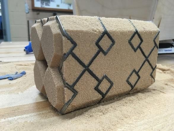
Table 1: Alloy Selection Overview

 Lattice Hammer
 Material Selection 60-40-18 Ductile Iron 8630 Steel

 Fluidity, Ductility, Minimal Good hardness, Hardenability,
 Key Advantages
 Shrinkage Toughness,

 The most important factor however in determining the alloy selection is the interaction between the
two metals at the bimetal interface. The liquid metal must retain sufficient heat upon contact with the
lattice material that the solid lattice material will partially melt and fuse with the steel casting. In
comparing the two selected alloys, 8630 Steel features a solidus temperature well above the solidus
temperature of 60-40-18 Ductile Iron as shown in Figure 8 and 9. In Figure 8, the steel will become fully
solidified as austenite at approximately 2640 °F (appr. 1450 °C). In Figure 9, Ductile Iron has a solidus
temperature of 2120 °F (1170 °C). For this reason, it can be expected that upon casting, the steel will
partially remelt and bond with the ductile iron to form a robust bimetal interface. In addition, it is
expected to form carbide at the interface when the remelted ductile iron solidifies. As a result, special
heat treatments will be required in subsequent processes as described in section 2.7.

 Figure 8: 8630 Steel Equilibrium Phase Transformation Plot
Figure 9: Ductile Iron Equilibrium Solidification Curve Plot

2.4 Hammer Structural Design

 The main hammer structure was developed based on the iconic Marvel Universe adaptation of
Thor’s hammer; however, the middle portion of the hammer was removed to reduce weight.
Nonetheless, the hammer faces and the hammer eye were retained from the original design. The faces
and hammer eye were connected by a diamond beam cross section, shown in Figure 10. This was
designed to be thick enough to allow for adequate liquid flow during casting but not so thick that
unnecessary weight was added. The hammer face was designed to be ¼” thick, which was selected
based on the hardenability chart for 8630. [16] A minimum hardness of 40 HRC is possible up to ¼” from
the quench surface when the hammer is face quenched. For a through hardened hammer face, ¼”
thickness was desirable.
Figure 10: Hammer Structure Design

 The hammer eye was designed dimensionally based on a standard blacksmithing hammer handle
featuring an oval eye. A 1° taper was added to the eye as shown in Figure 11, allowing for a secure
handle fitment through a kerf-and-wedge process. This process is demonstrated in Figure 12, drawn
from a publication of the Blacksmithing Organization of Arkansas. [17]

 Figure 11: 1° Taper Added to Hammer Eye
Figure 12: Proper Handle Mounting Procedure for Blacksmith Tools [17]

 Lastly, features were included on the backside of the hammer face to allow for full contact between
the lattice and the hammer structure, as shown in Figure 13. Built-up triangular extrusion features meet
precisely with the faces of the lattice structure. This not only gives the lattice structure something to
mount to but also increases the thermal modulus of the casting at these key locations to allow for
proper melting and fusion of the ductile iron lattice.

 Figure 13: Tetrakaidecahedron Lattice Fitted to Hammer Structure

 The lattice structure serves another purpose relating to the hammer structure. Because the beam
supporting the hammer faces is connected in the center of the face, excessive moment loads could
develop when the hammer is struck on the edges or corners of the faces. Because the lattice structure
connects to the hammer face around the edges and corners, it will resolve any moment load which
would otherwise be generated as well as absorb impact energy generated by sharp contact to the edges
of the hammer.
2.5 Casting Process Selection and Design

 To cast the complex geometry of the lightweight structure, the investment casting was an obvious
fit. Investment casting offers the ability to capture intricate details, produce thin wall castings, and
maintain excellent surface finish. [18] Additionally, investment casting allows for high mold preheat
temperatures (between 1600 and 2000 °F for ferrous alloys) to aid in complete filling of intricate
designs. [18] Although investment casting is significantly more labor intensive than other casting
methods and increases manufacturing cost in a commercial sense, investment casting is capable of
producing castings which are unattainable other means. Additionally, the improvement in surface finish
and design complexity often more than make up for the increase in production cost. For these reasons,
investment casting was selected as the casting method for producing the lightweight ductile iron lattice
structure.

 For the main hammer structure, sand casting was selected as the casting method. Although the
casting of the hammer structure required some unique engineering solutions to accommodate the
lattice structure, the overall design primarily featured standard geometries which are easily castable
through sand casting methods. The internal cavities and lattice features can be accommodated by a
sand core built around the lattice structure. High surface finish was not necessary for the interior of the
hammer, and the hammer faces would require polishing regardless of the casting method, so surface
resolution was not a primary concern in the selection of the casting method. For this reason, sand
casting was selected as the production method for the hammer structure.

2.6 Gating and Riser Design

 MAGMA was used to validate the castability of the proposed design as well as to develop an
appropriate feeding system for the casting. The ability of the bimetal casting to properly fuse and form a
strong interface was evaluated based on MAGMA simulation thermal analysis data. Filling temperature
simulations were also used to verify proper filling of the casting. Lastly, porosity was predicted through
simulation and accounted for by riser placement. Separate simulations were prepared for each stage of
the two-step casting process. First, the investment cast ductile iron lattice was simulated to verify
castability, determine appropriate pouring temperature, and determine the minimum preheat
temperature. Second, the steel hammer structure was simulated with the lattice chill feature
incorporated. These simulations together predicted the overall outcome of the casting process.

 The ductile lattice casting was simulated using the investment casting module of MAGMAsoft®. GJS-
400 Ductile Iron Alloy was selected from the MAGMA database for simulation purposes. A top-down
gating approach was adopted to achieve maximum head pressure for complete filling, as shown in
Figure X. A Foseco 2.5”x6” Kalpur sleeve was used in the simulation to serve as an insulated downsprue-
riser hybrid. Important MAGMA simulation parameters are presented in Table 2. Pouring time was
calculated using Equation 1 based on the combined weight of the casting and gating system (W) in lbm,
with the wall thickness coefficient (S) being 1.63. [19] The wall thickness coefficient was selected based
on established standards for a thin casting wall thickness according to published data. [19]

 Equation 1: = √
Table 2: Lattice Simulation MAGMA Parameters

 Critical Parameters Value Unit
 Casting System Weight 4.36 lbm
 Pouring Time 3.4 sec
 Shell Thickness 10 mm
 Pouring Temperature 2550 ˚F
 Shell Preheat Temperature 1750 ˚F
 Simulation Alloy Selection GJS-400

 A pouring temperature of 2550 ˚F (approx. 1400 °C) combined with an investment shell preheat of
1750 ˚F (950 °C) was chosen to maintain fluidity through the thin wall sections. From the MAGMA
database for GJS-400 Ductile Iron, the liquidus temperature for the material was 2135 °F (1168 °C). After
simulation, it was determined that the minimum temperature during filling was 2183 °F (1195 °C) as
shown in Figure 14, and therefore the mold could be expected to fill completely.

 Figure 14: MAGMAsoft® Investment Cast Lattice Gating

 Following the finalization of the lattice filling simulation, a green sand casting simulation was
developed for the steel hammer casting. The Ductile Iron Lattice was included in this simulation and
specified as a GJS-400 iron Chill. The steel casting alloy selected for this simulation was 4340 steel from
the MAGMA database. A Foseco Kalpur sleeve was added to the hammer eye structure and used as an
insulated downsprue and top riser combination. Risers were added to either end of the casting to feed
the hammer faces. One vent was added to the top of each hammer face to accommodate for low
permeability in the chemically bonded sand. A The final gating and riser system is shown in Figure 15.
Simulation parameters are shown in Table 3. Furan sand was selected as the mold material. The pouring
time was once again calculated according to Equation W, however this time a larger wall thickness
coefficient of 1.85 was selected. [19]

 Figure 15: Gating and Riser Design for Bimetal Hammer Casting

 Table 3: Hammer Structure MAGMA Parameters

 Critical Parameters Value Unit
 Casting System Weight 23.15 lbm
 Pouring Time 8.9 sec
 Sand Material Furan Sand
 Pouring Temperature 2912 ˚F
 Mold Temperature 80 ˚F
 Simulation Alloy Selection 4340

 From the MAGMA Simulations, the temperature profile of the casting was obtained to predict
the filling behavior of the casting, but also to predict the ability of the lattice to fuse with the steel
casting. From the temperature profile shown in Figure 16, the temperature of the liquid steel casting at
the surface of the lattice structure is shown to be well above the liquidus temperature of ductile iron
and therefore the two materials together should weld fully together.
Figure 16: Steel Casting Temperature Profile

 The MAGMA simulation results were also used to predict the severity of porosity in the hammer
face. It was found that negligible porosity defects were predicted to occur in the casting. The MAGMA
porosity simulation results are shown in Figure 17. A cross shaped facial feature was added to the
hammer face to prevent porosity from forming at the points of increased thermal modulus discussed in
the hammer structure design.

 Figure 17: Porosity Analysis of Bimetallic Hammer Casting
2.7 Heat Treatment Design

 Prior to the design of the heat treatment procedure, the chemistry of the two alloys used were
obtained through spectrometry. These are reported in Tables 4 and 5 in section 4.1. The exact
chemistries were used to generate cooling curves using JMatPro thermodynamic calculation software.
Continuous Cooling Transformation (CCT) curves were obtained and used to predict the microstructure
response to various heat treatment procedures.

 A normalizing procedure was first designed to relieve internal stresses within the casting and to
refine the grain structure. According to data published in the ASM handbook for heat treatment of low
alloy steel, the recommended normalizing temperature for 8630 steel is 1650 °F. [16] When normalizing,
the component should be held for approximately 1 hour per inch to bring the entire casting up to the
normalizing temperature. The part should then be removed to air cool to ensure the relief of residual
stresses while simultaneously refining the grain structure.

 Although the normalizing heat treatment was specifically selected from recommendations for
8630 steel, this process is also highly beneficial to improving the mechanical properties of the ductile
iron lattice. According to the ASM handbook “Heat Treating and Properties of Ductile Iron”, normalizing
is beneficial to most ductile iron castings, generally resulting in a fine pearlitic matrix. [20] This does,
however, largely depend on the alloy composition. Using CCT curves generated by JmatPro for the
measured Ductile Iron chemistry and shown in Figure 18, an average air-cooling rate should produce a
fully pearlitic matrix in the Ductile Iron. For this reason, the selected normalizing cycle was identified as
being beneficial to both alloys in the bimetallic casting.

 Figure 18: CCT Curve Generated from Measured Ductile Iron Chemistry
When the final hammer structure was cast, samples were taken for the purpose of designing and
validating a heat treatment procedure. A ductile iron sample was taken from the cast iron lattice and
inserted into a separate mold for the purpose of analyzing the bimetal composite interface and the
resulting microstructures of each alloy. This sample was then cut, polished, and prepared for
metallography examination. A tight metallurgical bonding was observed at the interface, as shown in
Figure 19.

 Ductile Interface
 Iron

 Steel

 1 cm

 Figure 19: As-Cast Sample Specimen for Analysis of the Bimetal Interface

 From the as-cast microstructure, several key insights were gathered which aided in designing a heat
treatment procedure. Metallography images of the bimetal interface show a solid interface region. In
Figure 20, a low magnification image of the interface region between the steel (right) and cast iron (left)
is shown. From this image however, it is abundantly clear that the rapid remelting and solidification of
the ductile iron resulting in carbide formation from the metastable eutectic transformation. The
metastable eutectic reaction is a controlled by cooling rate, nucleation potential in the melt, and alloy
content. [21] Because the ductile iron has been remelted, there will not be enough inoculant present to
nucleate graphite. Additionally, the fast melting and re-solidification rates will further favor iron carbide
formation due to higher undercooling. [21] This bimetal casting resulted in white iron forming in the
weld zone. A higher magnification image of the carbides resulting from this process is shown in Figure
21.
Steel Ductile
 Iron

 Figure 20: Low Magnification Image of Bimetal Interface Region

 Carbide

 Figure 21: High Magnification Image of Carbides Formed in the Cast Iron

 White Iron forming at the bimetal interface would be severely detrimental to overall mechanical
performance as form and propagate along the iron carbide plates, resulting in brittle behavior. For the
hammer to adequately withstand high impact loading the presence of iron carbide must first be
eliminated. For this reason, a malleable iron heat treatment procedure was adopted. This heat
treatment procedure was designed based on documentation from ASM handbooks on malleable iron
heat treatment as well as advice offered by Dr. Mingzhi Xu of Georgia Southern University and Dr. Von L.
Richards of Missouri S&T.
To begin the malleable iron heat treatment, the casting should be first held at 700 °F for 2 hrs. to
facilitate nitride precipitation. This step is important to allow for a nucleation site for graphite to grow as
the iron carbides are dissolved. Following nitride precipitation, the casting should be brought to 1750 °F
for first stage graphitization. [22] In this stage, iron carbides are dissolved, and malleable graphite is
formed. The casting was held at this temperature for 6 hrs to allow for maximum dissolution of the iron
carbides.

 One principal concern during this step was undesired grain growth in the steel portion of the
casting. However, because the steel chemistry contained 0.03 wt% Al, it can be expected that AlN will
have formed during the casting process. This nitride is a strong grain pinning agent, with a solubility well
above the proposed first stage graphitization temperature when calculated based on 0.03 wt% Al and an
estimated 90 ppm N. The equation to determine the solubility of AlN is shown in Equation 2, and
provided that the temperature remains under the solubility limit AlN will remain precipitated out of
solution and will prevent significant grain growth in the steel. [23]

 −6770
 Equation 2: log10 ([ ][ ]) = ( + 1.03)
 (° )

 After the completion of first stage graphitization, the casting should be removed and allowed to air
quench to near 1365 °F. Second state graphitization is then initiated by placing the casting immediately
in a furnace already held at 1365 °F. The furnace should be then shut off and the casting allowed to
slowly cool through the allotropic transformation range in the iron. This obtains an iron matrix
completely free of carbides. [22] Figure 22 provides the heat treatment cycle designed for the malleable
iron transformation.

 Malleable Iron Heat Treatment
 2000
 1800
 1600
 Temperature (°F)

 1400
 1200
 1000
 800
 600
 400
 200
 0
 0 1 2 3 4 5 6 7 8 9 10 11 12 13 14 15 16 17 18 19 20
 Time (Hrs.)

 Figure 22: Malleable Iron Heat Treatment Cycle Designed for the Hammer Casting
Following the malleable iron treatment, a Quench and Temper process (Q&T) was designed for the
purpose of hardening the hammer of the faces. In doing so however, the hammer surface must harden
while leaving the remainder of the casting ductile. To accomplish this, the lattice structure should be
well insulated from the casting, and the quench media should contact only the hammer faces. The
quench process was designed according to published data for 8630 steel available in the ASM handbook
for heat treating of low alloy steels. [16] According to this source, Oil, polymer, and water are all
appropriate quench media for 8630 steel. [16] In order to achieve a hardened surface, a severe quench
is necessary to avoid ferrite formation according to the CCT diagram produced for the given 8360 alloy
chemistry. According to the CCT diagram shown in Figure 23, the surface should be brought from the
austenizing temperature of 1630 °F (approx. 890 °C) to the martensite start temperature in under 10
seconds to achieve a primarily martensitic microstructure mixed with bainite. For this reason, water was
selected as the appropriate quench media to obtain the desired surface quench rate.

 Figure 23: CCT Diagram for 8630 Steel Produced by JMatPro

 Lastly, a temper process was designed to improve the overall toughness of the hammer face.
According to the ASM heat treatment handbook for low alloy steels, 86xx alloys respond similarly to
43xx series alloys of similar carbon content. [16] For this reason, it can be expected that the temper
response of 8630 would be similar to that of 4340. In a thesis published regarding 4340 steels for use in
ground engaging tools, an impact energy versus tempering temperature chart was presented and is
reproduced here in Figure 24. As shown in this figure, for stage 1 tempering, maximum toughness was
achieved at 200 °C. [24] For this reason, a 1 hr. temper at 400°F (approx. 200 °C) was selected to allow
for carbon redistribution and transition carbide formation without significantly affecting hardness. [24]
Figure 24: Tempering Temperature versus Impact Energy Chart for 4340 Steel Alloy [24]

 3. Manufacturing Methods
3.1 Additive Manufacturing of Patterns

 Additive manufacturing was used to produce the casting patterns for both the lattice structure and
the hammer casting. Fused Filament Fabrication (FFF) was primarily used in the making of both the
expendable investment casting pattern and the matchplate pattern used for casting the steel hammer
structure. PolyCast™, a novel investment casting PLA material produced by PolyMaker, was used to
produce the lattice structure. The structure was printed with minimal infill to reduce the thermal
expansion force experience by the shell. Figure 25 shows the printing in process on a Creality Ender 3
Pro series FFF printer. The printed lattice structure was then smoothed with ethanol to obtain a layer
free surface finish.
Figure 25: Printing the Lattice Structure on an FFF Printer

 FFF was also used to make the patterns for the hammer pattern. The hammer endcap and gating
features were 3D printed for mounting to the matchplate pattern. Riser alignment features were
included to easily mount Foseco Kalpur insulation sleeves. Additionally, a core box was produced by
additive manufacturing. These models were not designed to be expendable, so standard PLA material
was used. These components were printed on a Creality CR-10s pro FFF machine.

3.2 Investment Shell Production

 The investment casting mold was prepared by repeated coating with a ceramic slurry until a thick
shell was obtained. A ceramic slurry was prepared from fused silica flour and colloidal silica binder in a 2
to 1 ratio by weight. Fused silica flour was selected as the refractory for its low coefficient of thermal
expansion in fused silica form. [18] At elevated temperatures associated with ferrous casting, fused
silica will transform phases into cristobalite, a distinct silica phase which involves a volumetric change
which aids in breaking out the shell. Silica stucco was used to reinforce the ceramic shell between layers,
with fine mesh fused silica stucco being added to the first two primary coats, and coarse mesh fused
silica stuccoing the following backup coats. The primary slurry coats were covered in fine mesh stucco to
increase strength without compromising surface finish. Backup coats do not require the same surface
resolution but are rather designed to increase the strength and permeability of the mold and therefore
much coarser.

 According to the Polymaker application guide for PolyCast™, 5-6 backup coats are recommended to
prevent shell cracking during burnout. In producing the investment shell for the ductile iron lattice, 2
primary coats were applied followed by 6 backup coats. The final investment shell is shown in Figure 26.
The investment shell was allowed to dry for at least 4 hours in between each coat to allow the shell to
fully dry. It was then placed in an oven at low temperature (100 °F) for 12 hours to ensure the shell was
free of moisture. The shell was then aged for 24 hours in the oven at 270 °F to allow the PolyCast™
pattern to soften and pull away from the mold wall slightly, reducing thermal expansion stress upon
burnout. The investment shells were placed in a sintering furnace for 1 hour set at 1560 °F (850 °C) to
simultaneously sinter the shell and burn out the PolyCast™ pattern. According to Polymaker, the low ash
content of the patterns eliminates the need for washing prior to casting, and due to the difficulty of
removing water from the complex lattice channels, this step was skipped.

 Figure 26: Ductile Iron Lattice Investment Shell

3.3 Sand Mold Construction

 To produce the sand mold for casting the hammer structure, a matchplate pattern was produced
that was designed for use with chemically bonded sand. Because the cope and drag patterns for the
hammer casting are symmetrical, only one pattern was ultimately needed. For this reason, a flaskless
mold design was adopted so that the same pattern could be used to produce both the cope and the
drag. As shown in Figure 27, significant taper was incorporated into the flask to allow for easy mold
removal. Wood was used to form the core print for the lattice, and 3D printed patterns for the hammer
faces were adhered to the core print. Figure 27 shows the final matchplate pattern, designed to produce
a flaskless chemically bonded sand pattern.
Figure 27: Matchplate Pattern for Flaskless Chemically Bonded Sand Mold

 Prior to mold packing, the entire surface was coated with a zip-slip coating to facilitate clean
removal of the sand mold. The drag was produced by packing chemically bonded sand in the pattern.
The sand was allowed to cure for 10 minutes prior to removal. Next, a downsprue alignment feature was
attached to the top of the core print block and three Foseco sleeves were attached. One in the center
for the downsprue, and two on either side for the risers. Sand was again packed and allowed to cure,
then a vent was drilled through the mold for each hammer face. The final cope mold cavity is shown in
Figure 28. In this manner, both the drag and the cope of the sand mold were created.
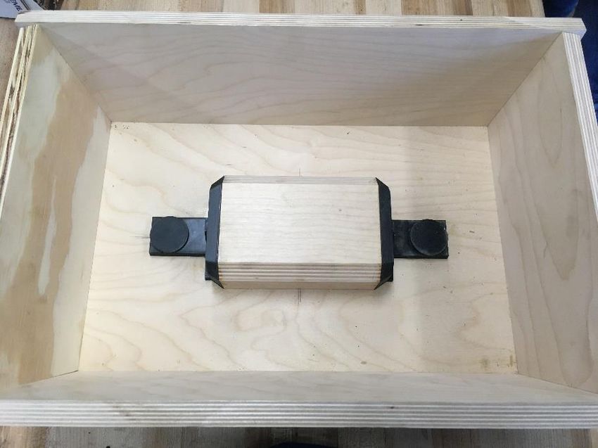
Vents
 Riser Riser

 Downsprue

 Figure 28: Cope Mold Cavity, Illustrating Downsprue, Vents, and Side Risers

 The lattice core was constructed from a three-part system attached to the finished lattice structure.
The investment shell was fully removed from the lattice and the downsprue was machined off. The faces
were ground perfectly flat to ensure proper bonding between the ductile iron and the cast steel. End
caps were attached to either side of the cast iron lattice. Attached to these endcaps was the diamond
cross beam structure. The hammer eye feature was placed down in the lattice and the diamond cross
beams met and attached with the eye via alignment pins. Ultimately, this formed a removable three-
part pattern for the sand core as shown in Figure 29(a). Chemically bonded sand was then carefully
packed into the cast iron lattice until the structure was fully infiltrated with sand as shown in Figure
29(b). This was allowed to cure fully before the three patterns were removed. Excess sand was carefully
carved off of the sides of the lattice, leaving a final sand core with the internal cavity forming the interior
hammer features as shown in Figure 29(c). The end faces of the lattice were left exposed to allow full
contact with the liquid steel.
A. B.

 C.
 Figure 29: Creation of the Sand Core

 Finally, the sand core was carefully inserted into the drag of the final mold and secured using mold
glue as shown in Figure 30(b). The two halves were carefully assembled, using the core as an alignment
feature. The two halves were sealed with mold glue and the mold was ready for casting. The final mold
is shown in Figure 30(a).

 A. B.
 Figure 30: Final Sand Mold (Left) and Internal Iron Lattice Core (Right)
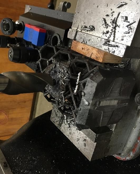
3.4 Casting Process

 The final casting of both the ductile iron lattice and the steel hammer was done with the assistance
of Carolina Metal Casting as a part of their normal production pour. Both melts were done in an
InductoTherm induction furnace, and chemistry samples were obtained from each heat for accurate
interpretation of the casting results.

 To cast the ductile iron lattice, the investment shell was first preheated to 1850 °F (approx. 1000 °C)
to ensure complete filling of the casting. This was removed from the furnace moments before the pour
took place and wrapped in kaowool to retain maximum heat. The ductile iron was poured at 2636 °F
(approx. 1400 °C). The steel casting was performed with the mold at room temperature. In this case,
8630 steel was poured at 3059 °F (approx. 1680 °C).

3.5 Postprocessing

 Following the casting process, postprocessing was performed in the Georgia Southern foundry and
machine shop. The final casting was first normalized prior to machining to relieve any internal stresses
resulting from the bimetal casting process. Next, the risers and most of the downsprue was cut off using
a band saw. The remainder of the downsprue was first drilled out, as shown in Figure 31, then milled off.
Additionally, the top and bottom faces of the hammer eye were machined flat. Next, a slot was
machined for the hammer eye, and a taper was ground into the feature to allow for the handle to be
secured by a kerf-and-wedge method. The faces of the hammer were finished by surface milling to
obtain an even surface, and the bevels were ground flat using a belt sander.

 Figure 31. Machining off the Downsprue

 Unfortunately, the casting possessed one major flaw which required an additional step of post
processing. After the casting had been cleaned up, it was found that the steel casting did not fuse
properly to the ductile iron casting in selected regions of higher stress due to the mismatch of thermal
expansion coefficient between the cast iron and steel. For this reason, additional welding was required
to complete the casting. MIG welding was used to join the two castings. The entire casting was first
preheated in the heat treatment oven to 400 °F. Heat was maintained at localized points with a
handheld torch while the lattice was welded to the steel casting. The weld beads were then ground flat
to the surface and cleaned up using a rotary tool and grinding stones.

3.6 Heat Treatment

The individual heat treatment procedures were carried out according to the designs adopted for the
normalization, malleable iron treatment, and quench and temper processes. One normalization cycle
was performed on the casting prior to post processing. Next, after all machining, welding, and major
grinding operations were complete, one normalization cycle was performed to prepare the casting for
malleable iron heat treatment. Prior to this however the casting was carefully wrapped in steel foil to
form an airtight package as much as possible to prevent excessive decarbonization of the casting. The
malleable iron heat treatment was carried out, followed by two more normalization cycles to counter
any potential grain growth in the steel. Lastly, the quench and temper processes were completed as
designed. Prior to the austenization for the quench, the steel foil was removed from the casting and the
lattice structure was packed and then wrapped with kaowool to isolate the ductile iron lattice from the
quench. Once the casting was at room temperature after the quench process it was immediately placed
in a convection oven to temper. The complete thermal processing cycle is shown in Figure 32.

 Complete Casting Heat Treatment Procedure
 2000
 Normalization Normalization
 1800
 Cycles Cycles
 1600
 Q&T
 1400
 Temperature (°F)

 1200

 1000

 800

 600 Malleable Iron
 400
 Treatment

 200

 0
 0 1 2 3 4 5 6 7 8 9 10 11 12 13 14 15 16 17 18 19 20 21 22 23 24 25 26 27 28 29 30 31 32 33 34 35
 Time (Hrs.)

 Figure 32: Complete Heat Treatment Procedure Performed on Bimetal Casting
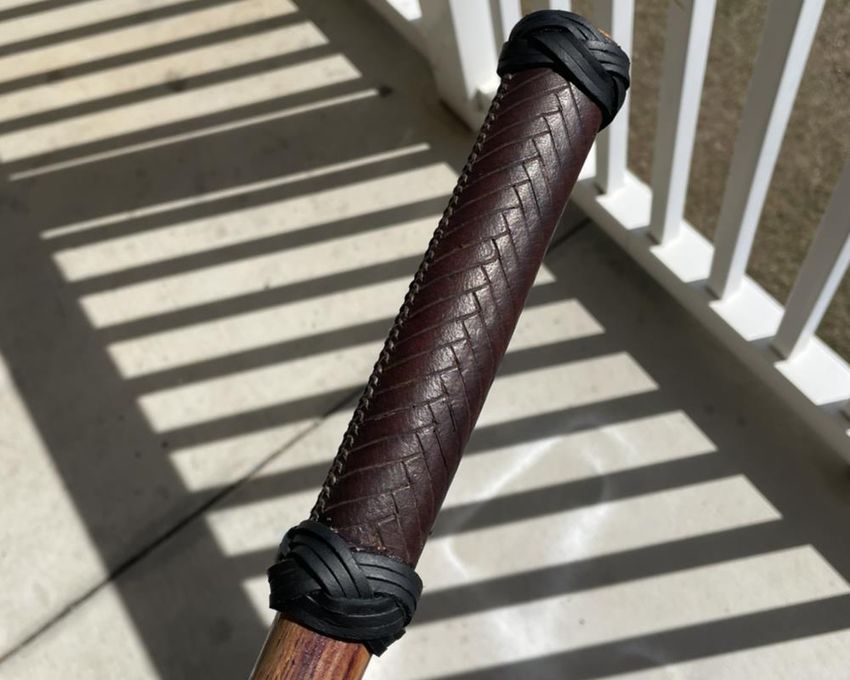
3.7 Final Preparation

 Finally, once the casting was completely machined to net shape and the heat treatment process was
complete, the hammer was prepared for its final appearance. The casting was placed in a vibratory
tumbler to aid in removing the scale and oxides formed on the surface during the heat treatment
procedure. It was then thoroughly sand blasted to remove any remaining debris from the interior
crevasses of the lattice. Next, to prevent the cast iron lattice and interior low alloy steel from rusting,
the lattice and interior of the casting was seasoned in a manner similar to that used on cast iron
cookware. Spray oil was applied to the interior of the casting and it was placed in a convection oven at
low heat. This was repeated several times to allow a thick seasoning coat to form, giving the interior of
hammer an appealing matte black texture while simultaneously preventing unwanted oxidation. The
faces of the hammer and the sides of the lattice were then polished using a buffing wheel and buffing
compound until a near mirror finish was achieved. A total mirror finish was not targeted as this would
amplify any scratches which will form over the usage cycle of any hammer implement.

 A hickory engineer’s hammer handle was sourced from a blacksmithing equipment supplier and
customized to fit the hammer weight and size. An oval handle cross section was selected to prevent the
hammer from twisting or sliding easily in the operator’s grip. The handle was shortened to improve the
overall balance and fitted to the hammer eye. Goatskin was hand tooled to provide extra texture and
grip security, then was wet molded to match the hammer handle profile and laced in place. Decorative
Turks head knots were added above and below the grip to provide both a firm hand stop and to improve
the overall aesthetic. The final hammer handle is shown in Figure 33.

 Figure 33: Handle Wrapped in Wet Molded Hand-tooled Goatskin and Finished with Turks Head Lacing

 Lastly, the hammer was mounted to the handle through a kerf-and-wedge process. After the handle
was fitted snugly to the hammer eye using sandpaper, two perpendicular kerfs were cut into the handle.
The handle was installed firmly into the hammer, and wedges were pounded into the kerf slots. The
wedges were cut off flush with the top of the handle, leaving the handle securely mounted hammer as
shown in Figure 34.

 Figure 34: Handle Mounted Securely via Kerf-and-Wedge Process

 4. Results and Discussion
4.1 Final Alloy Composition

 Samples were collected prior to pouring at Carolina Metal Casting. These were used to obtain the
exact chemistry composition of the obtained 8630 steel, shown in Table 4. For the 8630 Steel chemistry,
the measured results are compared against ASTM A29 published standards. It was found that all alloying
elements fell well within acceptable ranges published for 8630 steel. For this reason, it was deemed that
the target chemistry was successfully achieved.
Table 4: Final 8630 Alloy Chemistry from Spectrometry Analysis

 Alloy Element Content (wt.%) Target per ASTM Within Acceptable
 A29 (wt %) [25] Range? (T/F)
 Fe 97.1
 C 0.288 0.28-0.33 T
 Si 0.332 0.15-0.35 T
 Mn 0.788 0.70-0.90 T
 P 0.0157 0.035 (max) T
 S 0.0062 0.040 (max) T
 Cr 0.522 0.40-0.60 T
 Mo 0.198 0.15-0.25 T
 Ni 0.632 0.40-0.70 T
 Al 0.0315
 Cu 0.0765
 Ti 0.0022
 V 0.0039

 Unlike steel, cast irons are typically graded by mechanical properties rather than by alloy content.
For this reason, chemistry ranges are not specified by ASTM standard and alloy content generally differs
from foundry to foundry. The final achieved ductile iron chemistry is shown below in Table 5. Based on
the Carbon and Silicon content, the carbon equivalent was calculated and found to be 4.17 according to
Equation 3. This is below the eutectic composition, yielding a hypoeutectic ductile iron.

 Table 5: Final Ductile Iron Alloy Chemistry from Spectrometry Analysis

 Alloy Element Content (wt.%)
 Fe 93.7
 C 3.36
 Si 2.43
 Mn 0.332
 P 0.0221
 S 0.0064
 Cr 0.0275
 Mo 0.0060
 Ni 0.0113
 Al 0.0094
 Cu 0.0232
 Mg 0.0400
 Ti 0.0026
 V 0.0022

 1
 Equation 3: . . ( %) = +
 3
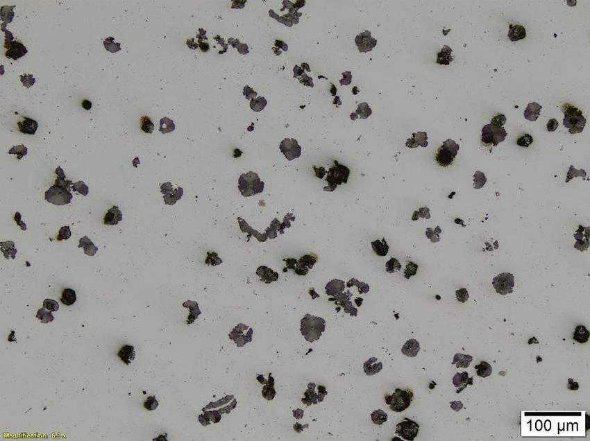
4.2 Microstructure Analysis and the Bimetal Interface
 From the bimetallic cast sample, it is clear that the proposed hypothesis was valid for the bimetal
casting design. The experimental casting validates that Steel, poured at a temperature sufficiently above
the solidus of iron, will form a robust fusion zone between the materials when poured onto solid iron.
Figure 19 shown previously, depicting the bimetallic interface at a macro-scale, shows a seamless
interface between the two materials. Figure 35 shown here provides higher magnification images of the
interface between the two materials, demonstrating a unified metallurgical bond with no major defects.
 Steel

 Cast Iron

 Figure 35: Medium Magnification Image of Bimetal Interface As-Cast

 The test sample was also heat treated in a similar manner as the actual hammer casting. The entire
heat treatment procedure shown in Figure 32 was followed as closely as possible to predict the final
microstructure of the hammer. A cross section of the sample was normalized twice and treated to
convert the carbides to malleable iron. Following this stage, the sample was divided in half. Half of the
sample was kept unquenched to examine the microstructure following the white iron treatment. The
other half of the sample was then quenched to obtain the final microstructure present in the hammer.
In this way, the as-cast, malleable iron treated, and quenched microstructures were all obtained for
studying the final hammer microstructure.
 After the malleable iron heat treatment, the sample was polished and examined unetched to show
good contrast between the iron matrix and the graphite phase. From these images, it was found that
finely dispersed malleable graphite nodules occurred evenly throughout the sample from the carbide
dissolution as shown in the low magnification image in Figure 36. During the malleable iron treatment,
carbon from the carbides will diffuse and nucleate, growing on nitrides and other precipitates in the iron
matrix to near-nodular shape in order to minimize the total free energy of the system. A higher
magnification image of the malleable graphite morphology is shown in Figure 37.
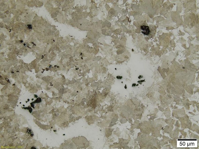
Figure 36: Low Magnification Image of the Malleable Iron Graphite Morphology

 Figure 37: High Magnification Image of the Malleable Iron Graphite Morphology

 After the malleable treatment, both the iron and the steel microstructures contain pearlite and
ferrite. The samples were etched using a 2% Nital solution to expose the iron matrix. Figure X shows the
etched medium magnification images of the cast iron matrix (Figure 38(a)) and the cast steel matrix
(Figure 38(b)). As shown in Figure Xa, the coarse pearlite grain structure with significant amounts of
ferrite indicates a slow cooling rate and low overall mechanical properties. The microstructure of steel
shown in Figure 38(b) also contains significant ferrite content, resulting in low hardness.
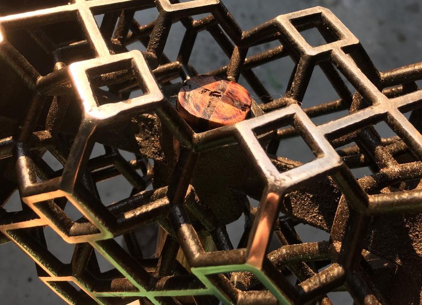
Ferrite

 Pearlite

 a.)

 b.)

Figure 38: Medium Magnification Images of Unquenched Malleable Treated Cast Iron (a.) and Steel (b.)

 After the sample was reaustenitized and quenched, the overall microstructure is very different and
much better suited to impact tooling applications. The quench sample was deep etched to contrast the
bainitic and martensitic grain structures. Figure 39 shows a clear contrast in the quenched cast iron
microstructure of bainite mixed with martensite and malleable graphite. In the quenched cast iron
sample, it is clearly shown why the ductile iron lattice should be well insulated against the quench
effects. The blue acicular grains are upper bainite. Coarse acicular bainite grains are common sources of
crack propagation and should be avoided.[23] Additionally, the grains which etched brown are plate
martensite, which form at high carbon content and are mixed with retained austenite, which are
observed in the white particles. Plate martensite is also quite brittle and known for crack propagation.
For this reason, it is more beneficial for the ductile iron lattice to resemble the unquenched
microstructure than the quenched microstructure. Rockwell hardness readings of the quenched cast
iron microstructure were taken and averaged at 59 RHC, far too hard and brittle for impact applications.

 Figure 39: High Magnification Image of Quenched Cast Iron Matrix

 Examining the quenched steel microstructure, a very fine microstructure of bainite and
 martensite is observed which is well suited to a combination of hardness and toughness. In Figure
 40, a very fine matrix of evenly mixed bainite and lath martensite is observed. Unlike plate
 martensite, lath martensite is formed at lower carbon content. Of the martensite which forms,
 when the carbon content is under 0.5 wt% almost 80% of the martensite formed will be lath. [23]
 Because lath martensite is much finer and less acicular, after tempering, it will yield much higher
 toughness compared to plate martensite and is desired for medium hardness/high toughness
 applications. In Figure 40, the martensite appears as light tan-colored grains. The darker grains are
 bainitic. Bainite formation during quench is almost unavoidable as shown in the CCT curve for 8630
 steel shown in Figure 23. Bainite shows a desirable combination of strength and ductility when it is
 not of coarse acicular morphology and in this case is highly desirable. The hardness of the quenched
 steel sample was found to be 45 RHC, almost exactly the target hardness for a quality hammer. This
 mixture of hardness and toughness was obtained through a mixed martensitic and bainitic
 microstructure obtained through quenching.
Figure 40: High Magnification Image of Quenched 8630 Steel Microstructure

4.3 Analysis of Fusion Defects in the Hammer Casting

 As the sample weld experiment previously discussed showed excellent fusion at the interface, the
most important question to discuss is why the lattice structure did not weld with the steel casting.
Further experimentation will need to be done before a definitive answer can be given, but it is
suspected that this could be attributed to differences in thermal expansion between the two materials.
Because the thermal expansion of steel and iron differ, they will expand and contract at different rates,
causing warping and uneven contraction during cooling which could have pulled the two interfaces
apart.

 Although the bimetal fusion between the two castings was not completely successful during the
first production run, experimental validation shows that this indeed is a viable casting technique for a
wide range of applications. By preheating the sand core prior to pouring, or by transitioning to
investment casting techniques, it could be possible to ensure a complete metallurgical bond between
the two castings, successfully harnessing the desirable material properties of both materials to address a
single engineering application.

 5. Conclusion
 By further developing cutting edge research being performed in the field of metal casting and
bimetal composites, the Georgia Southern Cast in Steel competition team successfully produced a
bimetal Thor’s hammer inspired by influences from Nordic mythology and the Marvel™ comic book
universe. The hammer consisted of a hammer skeletonized structure cast in 8630 steel supported by a
cast ductile iron lightweight lattice structure. This bimetal casting combined technology in additive
manufacturing, investment casting, sand casting, heat treatment, and metallurgy to develop a unique
engineering solution to the requirements put forward by the Steel Founder’s Society of America. The
You can also read