Retrofitting Vegas: Implementing Energy Efficiency in Two Las Vegas Test Homes - S. Puttagunta Consortium for Advanced Residential Buildings
←
→
Page content transcription
If your browser does not render page correctly, please read the page content below
Retrofitting Vegas: Implementing
Energy Efficiency in Two Las
Vegas Test Homes
S. Puttagunta
Consortium for Advanced Residential Buildings

April 2013

NOTICE

  This report was prepared as an account of work sponsored by an agency of the
  United States government. Neither the United States government nor any agency
  thereof, nor any of their employees, subcontractors, or affiliated partners makes any
  warranty, express or implied, or assumes any legal liability or responsibility for the
  accuracy, completeness, or usefulness of any information, apparatus, product, or
  process disclosed, or represents that its use would not infringe privately owned rights.
  Reference herein to any specific commercial product, process, or service by trade
  name, trademark, manufacturer, or otherwise does not necessarily constitute or imply
  its endorsement, recommendation, or favoring by the United States government or
  any agency thereof. The views and opinions of authors expressed herein do not
  necessarily state or reflect those of the United States government or any agency
  thereof.

           Available electronically at http://www.osti.gov/bridge

      Available for a processing fee to U.S. Department of Energy
                    and its contractors, in paper, from:
                       U.S. Department of Energy
             Office of Scientific and Technical Information
                                P.O. Box 62
                       Oak Ridge, TN 37831-0062
                           phone: 865.576.8401
                             fax: 865.576.5728
                  email: mailto:reports@adonis.osti.gov

              Available for sale to the public, in paper, from:
                      U.S. Department of Commerce
                  National Technical Information Service
                           5285 Port Royal Road
                           Springfield, VA 22161
                           phone: 800.553.6847
                             fax: 703.605.6900
                     email: orders@ntis.fedworld.gov
             online ordering: http://www.ntis.gov/ordering.htm

Printed on paper containing at least 50% wastepaper, including 20% postconsumer waste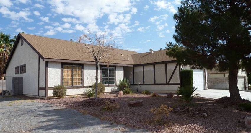
Retrofitting Vegas: Implementing Energy Efficiency in
                Two Las Vegas Test Homes

                            Prepared for:
             The National Renewable Energy Laboratory
On behalf of the U.S. Department of Energy’s Building America Program
          Office of Energy Efficiency and Renewable Energy
                    15013 Denver West Parkway
                         Golden, CO 80401
             NREL Contract No. DE-AC36-08GO28308

                            Prepared by:
                            S. Puttagunta
                    Steven Winter Associates, Inc.
                                of the
           Consortium for Advanced Residential Buildings
                        61 Washington Street
                         Norwalk, CT 06854

              NREL Technical Monitor: Cheryn Metzger
          Prepared under Subcontract No. KNDJ-0-40342-00

                             April 2013

                                 iii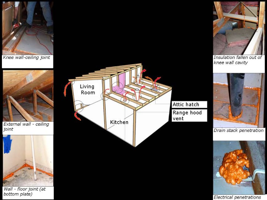
(This page left blank)

          iv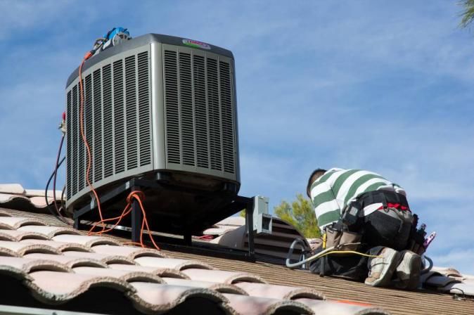
Contents
List of Figures ............................................................................................................................................ vi
List of Tables ............................................................................................................................................. vii
Definitions ................................................................................................................................................. viii
Executive Summary ................................................................................................................................... ix
Acknowledgments ...................................................................................................................................... x
1 Introduction ........................................................................................................................................... 1
      1.1 Carmen .................................................................................................................................2
          1.1.1 Building Envelope ...................................................................................................3
          1.1.2 Mechanical Equipment ............................................................................................6
      1.2 Sierra Hills ...........................................................................................................................8
          1.2.1 Building Envelope ...................................................................................................9
          1.2.2 Mechanical Equipment ..........................................................................................11
2     Research Goals................................................................................................................................... 13
3     Design Specifications and Energy Modeling................................................................................... 14
      3.1 Carmen ...............................................................................................................................14
      3.2 Sierra Hills .........................................................................................................................16
4     Implementation ................................................................................................................................... 19
      4.1 Air Sealing .........................................................................................................................20
      4.2 Heating, Ventilation, and Air Conditioning.......................................................................23
          4.2.1 Carmen ...................................................................................................................25
          4.2.2 Sierra Hills .............................................................................................................28
5     Final Performance Modeling ............................................................................................................. 32
      5.1 Carmen ...............................................................................................................................32
      5.2 Sierra Hills .........................................................................................................................35
6 Cost Analysis ...................................................................................................................................... 39
7 Conclusions ........................................................................................................................................ 44
References ................................................................................................................................................. 46

                                                                               v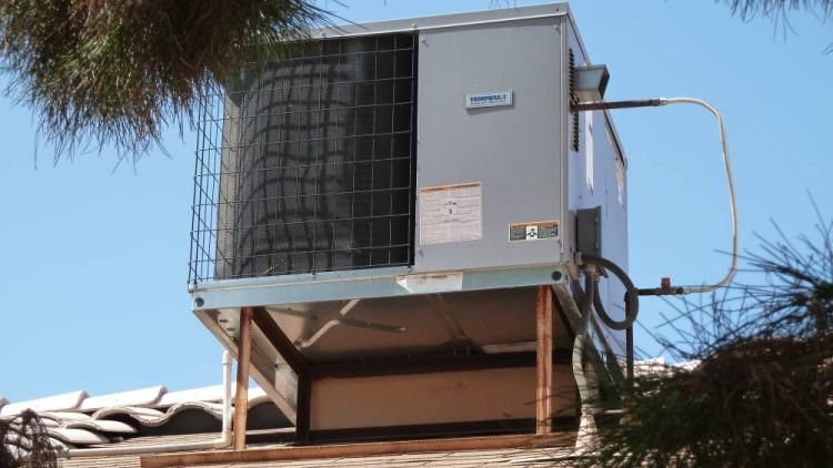
List of Figures
Figure 1. Projected foreclosure rates by state ......................................................................................... 1
Figure 2. Exterior photo of the Carmen home.......................................................................................... 2
Figure 3. Ceiling leakage points at the Carmen home ............................................................................ 4
Figure 4. Top plate of interior walls cut out for electrical runs into partition walls ............................. 4
Figure 5. Discovery of poor insulation in the kitchen kneewall ............................................................. 5
Figure 6. Haze between the window panes is evidence of a broken hermetic seal ............................. 6
Figure 7. Lack of air sealing around exterior doors ................................................................................ 6
Figure 8. From left clockwise: supply plenum located in the vented attic, roof-mounted packaged
furnace/AC, and insulation unwrapping from flex duct because the exterior vapor barrier had
deteriorated ........................................................................................................................................... 7
Figure 9. Atmospheric gas water heater located in the attached garage ............................................. 8
Figure 10. Exterior photo of the Sierra Hills home .................................................................................. 8
Figure 11. (Left) Top plate corner leakage; (center) kitchen exhaust ducting through interior wall
without backdraft damper; (right) leakage around garage door from lack of weather stripping . 9
Figure 12. Leakage in ceiling plane ......................................................................................................... 10
Figure 13. Poor insulating of partially vaulted ceiling kneewalls ........................................................ 10
Figure 14. Interior wall cavities that are directly communicating with the attic ................................. 11
Figure 15. Rooftop packaged furnace/AC located at the Sierra Hills home ....................................... 12
Figure 16. Atmospheric water heater located in the garage of the Sierra Hills home ....................... 12
Figure 17. Specification optimization analysis during the design stages of the Carmen home ...... 16
Figure 18. Specification optimization analysis during the design stages of the Sierra Hills home . 18
Figure 19. Field training flyer ................................................................................................................... 20
Figure 20. Examples of air sealing at the Carmen home ...................................................................... 21
Figure 21. Existing package furnace/AC unit being craned off of the Sierra Hills home .................. 23
Figure 22. New outdoor heat pump unit being installed at the Sierra Hills home.............................. 24
Figure 23. Spot ERVs installed in both homes to provide balanced whole-house ventilation ......... 24
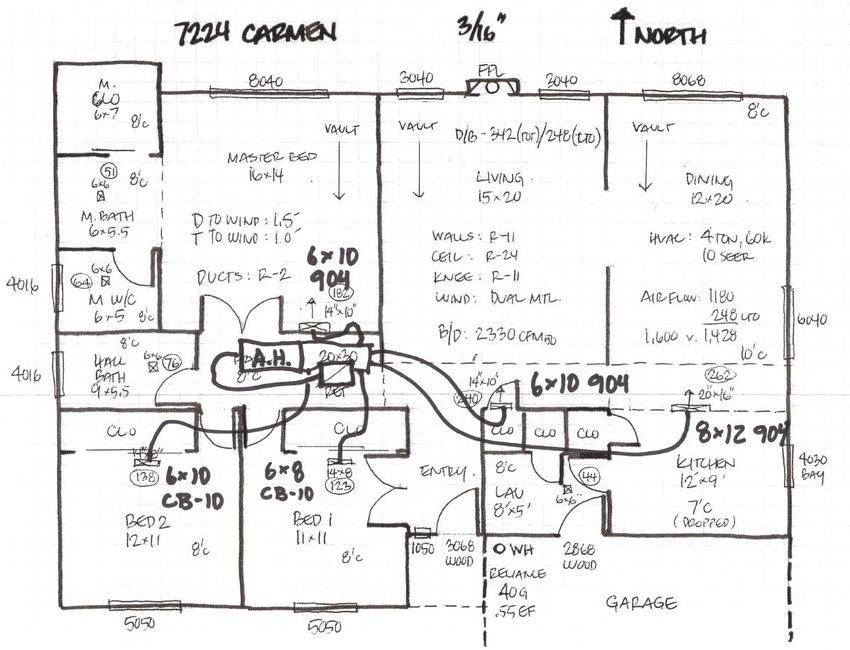
Figure 24. The radial HVAC design for the Carmen home .................................................................... 26
Figure 25. Radial HVAC system as installed at the Carmen home ...................................................... 26
Figure 26. Mastic being applied to inside of flexduct jacket before being slipped over and secured
to a branch takeoff elbow with compression bands ....................................................................... 27
Figure 27. Initial radial HVAC design for the Sierra Hills home ........................................................... 29
Figure 28. Relocating pressure boundary to bring ductwork into conditioned space. On the left is
the existing configuration; the right image shows the new configuration................................... 30
Figure 29. Pressure boundary being moved up to the bottom of the scissor trusses to allow ducts
to remain within the building envelope ............................................................................................ 30
Figure 31. Final energy savings prediction for the Carmen home ...................................................... 34
Figure 32. Cumulative contribution to total energy savings, by measure and end use, for the
Carmen home ...................................................................................................................................... 35
Figure 33. Final energy savings prediction for the Sierra Hills home ................................................. 37
Figure 34. Cumulative contribution to total energy savings, by measure and end use, for the Sierra
Hills home............................................................................................................................................ 38
Unless otherwise noted, all figures were created by CARB.
vi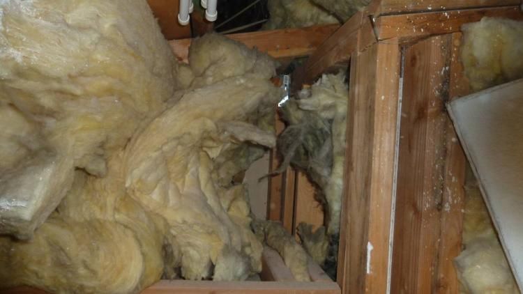
List of Tables
Table 1. Final Estimated Performance of the Carmen and Sierra Hills Homes ................................... ix
Table 2. Existing Conditions at the Carmen Home .................................................................................. 3
Table 3. Existing Conditions at the Sierra Hills Home ............................................................................ 9
Table 4. Inputs of Economic Analysis .................................................................................................... 14
Table 5. BA Proposed Specifications at the Carmen Home ................................................................. 15
Table 6. BA Proposed Specifications at the Sierra Hills Home ............................................................ 17
Table 7. BA Revised Specifications at the Sierra Hills Home............................................................... 17
Table 8. Least Cost Optimization Specifications at the Sierra Hills Home ......................................... 18
Table 9. Air Sealing Results at the Carmen Home ................................................................................. 22
Table 10. Air Sealing Results at the Sierra Hills Home ......................................................................... 22
Table 11. Air Balancing Results at the Carmen Home .......................................................................... 28
Table 12. Verification of Suitable Return Air Pathways at the Carmen Home .................................... 28
Table 13. Air Balancing Results at the Sierra Hills Home ..................................................................... 31
Table 14. Verification of Suitable Return Air Pathways at the Sierra Hills Home............................... 31
Table 15. Pre- and Post-Retrofit HERS Indexes for the Vegas Retrofits ............................................. 32
Table 16. Summary of Specifications at the Carmen Home ................................................................. 33
Table 17. Summary of Specifications at the Sierra Hills Home ............................................................ 36
Table 18. Comparison of Annualized Energy-Related Costs Based on Length of Mortgage and
   Analysis Period ................................................................................................................................... 39
Table 19. First Costs of Efficiency Measures at the Carmen Residence ............................................ 41
Table 20. First Cost of Efficiency Measures at the Sierra Hills Residence ......................................... 42
Table 21. Final Estimated Performance of the Two Test Homes ......................................................... 44

Unless otherwise noted, all tables were created by CARB.

                                                                          vii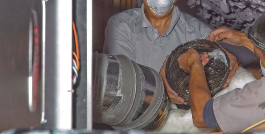
Definitions
AC            Air conditioner
ACH50         Air changes per hour at 50 Pascals
AFUE          Annual fuel utilization efficiency
ASHP          Air source heat pump
BA            Building America
BARA          Building America Retrofit Alliance
BEopt         Building Energy Software
Btu/h         British thermal units per hour.
CARB          Consortium for Advanced Residential Building
CFL           Compact fluorescent lamp
cfm           Cubic feet per minute
EPS           Expanded polystyrene foam
ERV           Energy recovery ventilator
HERS          Home Energy Rating System
HSPF          Heating Season Performance Factor
HVAC          Heating, Ventilation, and Air Conditioning
in. w.c.      Inches of water column
IR            Infrared
kWh           Kilowatt-hour
LAMEL         Lighting, appliances, and miscellaneous electric loads
LED           Light-emitting diode
NSP           Neighborhood Stabilization Program
RESNET        Residential Energy Services Network
SEER          Seasonal energy efficiency ratio
SPB           Simple payback

                                      viii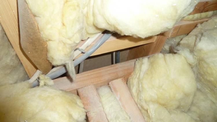
Executive Summary
In 2009, Nevada received nearly $40 million in Neighborhood Stabilization Program funds from
the U.S. Department of Housing and Urban Development. The purpose of this funding was to
stabilize communities that have suffered from foreclosures and abandonment. In an effort to
provide guidance to local officials and maximize how effectively this Neighborhood
Stabilization Program funding is used in retrofitting homes, the Consortium for Advanced
Residential Buildings (CARB) provided design specifications, energy modeling, and technical
support for the Building America Retrofit Alliance (BARA) team and its local partners—Better
Building Performance, Nevada ENERGY STAR® Partners Green Alliance, and Home Free
Nevada—for two retrofit test homes. One home was to demonstrate a modest retrofit and the
other a deep energy retrofit.

The Carmen and Sierra Hills homes demonstrate how cost effectively energy-efficient upgrades
can be implemented in the hot, dry Southwest climate. The homes were used as an educational
experience for home performance professionals, building trades, remodelers, and the public. In-
field trainings on air sealing, HVAC upgrades, and insulating were provided to local contractors
during the retrofit. BARA documented these retrofits through a series of video presentations,
beginning with a site survey and concluding with the finished remodel and test out.

Through this project, CARB has provided two robust solution packages for retrofitting homes
built in this region between the 1980s and early 1990s without substantially inconveniencing the
occupants. The Building America solution packages for the two test homes were fairly similar
(though the Carmen home did have a solar thermal water heating system) and achieved the
targeted energy savings (over the pre-retrofit home) of 30% or more at the Sierra Hills home and
50% or more at the Carmen home. The lower savings level at the Sierra Hills home was
primarily a result of mechanical equipment updates that were performed over the past decade.
The final estimated performance of these homes is summarized in Table 1.

               Table 1. Final Estimated Performance of the Carmen and Sierra Hills Homes

                         Source       Annual           Annualized                Home Energy Rating
          Home           Energy        Utility       Energy Related                  System Index
                         Savings      Savingsa        Cost Savingsb           Pre-Retrofit Post-Retrofit
      Carmen              51%          $1,138             $845                    126            66
    Sierra Hills          34%           $480              $321                     98            61
    a
        $0.1175/kWh +$10 monthly charge, $0.7666/therm + $9 monthly charge
    b
        30-year mortgage, 4.0% loan interest rate, 1.6% inflation rate, 3.0% discount rate (real), 0% fuel
         escalation rate

The solution packages focused on air sealing the building envelope where accessible and
replacing windows with double-pane low-e retrofit windows. This reduced solar heat gain and
allowed rough openings to be better air sealed. Another essential strategy was to simplify the
design and distribution of the high efficiency HVAC systems for optimum system performance.
This included bringing the ductwork into conditioned space.

                                                            ix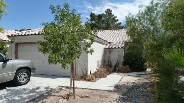
Acknowledgments
Steven Winter Associates, Inc. acknowledges the U.S. Department of Energy Building America
program and its funding and support of development of this technical report as well as research
that informed it. A special thanks to Annette Bubak, Brandon Kephart, and Kelly Thomas of
Better Building Performance, Richard Chitwood of Chitwood Energy Management, and Darren
Harris, Tami Svarfar, and Don Whipple of the BARA team.

                                               x
1 Introduction
In 2009, Nevada received almost $40 million in Neighborhood Stabilization Program (NSP)
funds from the U.S. Department of Housing and Urban Development to stabilize communities
that have suffered from foreclosures and abandonment. Nevada suffered the highest rates of
foreclosure in the nation between 2008 and 2009 (see Figure 1).
Figure 1. Projected foreclosure rates by state
Nevada used this funding to develop a renovation program that purchases foreclosed properties,
performs audits on the homes to assess code compliance, energy efficiency, and health issues,
and implements the recommended repairs from these inspections. These homes are then resold to
qualifying buyers or held by housing authorities for rental.
A key change in the program requirements since 2011 was a focus on neighborhood-scale
retrofits. The program requires that multiple homes in the same neighborhood be retrofitted.
Tens of thousands of homes were built in this region over the past decades with hardly a nod
toward energy efficiency. With a desire to make these homes affordable (low first cost) and
sustainable (low operational costs), the focus has shifted from finishes, aesthetics, and curb
appeal to home performance. Over the years, the U.S. Department of Energy’s Building America
(BA) program has provided support for this performance-based, whole-house remodeling
approach and has educated the industry and homeowners about economically sound measures
and strategies that result in energy-efficient, healthy, comfortable, and durable homes.
In an effort to maximize how effectively this NSP funding is used to retrofit homes, the
Consortium for Advanced Residential Buildings (CARB) provided design specifications, energy
modeling, and technical support for the Building America Retrofit Alliance (BARA) team and its
local partners—Better Building Performance, Nevada ENERGY STAR® Partners Green
Alliance, and Home Free Nevada—for two retrofit test homes. Two homes in the Las Vegas
1NSP were selected as test homes to demonstrate how cost-effective energy efficiency upgrades
could be incorporated into these retrofits. These two demonstration homes were used as an
educational experience for home performance professionals, building trades, remodelers, and the
public. In-field trainings on air-sealing, heating, ventilation, and air conditioning (HVAC)
upgrades, and insulating were provided to local contractors during the retrofit. BARA
documented these retrofits through a series of video presentations, beginning with a site survey
and concluding with the finished remodel and test out.
The two test homes, the Carmen and Sierra Hills, are located in an area with one of the greatest
number and highest percentage of foreclosed homes in the city. In this area, more than 11% of
the existing housing stock is in foreclosure, equating to more than 8,100 homes, many of which
are vacant or abandoned.
The original scopes of work and cost estimates for the proposed NSP retrofits of these two
homes were provided to CARB. After doing an initial energy audit of both homes, CARB
performed energy modeling of the home conditions, the NSP proposed specifications, and CARB
recommended specifications to achieve 30%–50% source energy savings over the existing
conditions. Though some structural and cosmetic improvements were also included, this effort
focused on the energy improvements and associated costs.
1.1 Carmen
The Carmen home is a 1,521-ft2 ranch built in 1983. This single-family detached home has three
bedrooms, two baths, and an attached garage. At the height of the housing boom, it was valued
as high as $285,000, 1 but now its estimated value is $97,400. 2 The price range for homes in this
neighborhood is $70,000–$130,000. The home was dated, but its overall condition was livable
after a thorough cleaning and repair of a couple broken windows.
Figure 2. Exterior photo of the Carmen home
1
Based on information from www.zillow.com for July 2006.
2
Based on information from www.zillow.com for February 2012.
2Table 2 provides a summary of the Carmen home’s conditions.
Table 2. Existing Conditions at the Carmen Home
Building Component Existing Condition
Foundation Slab-on-grade, uninsulated
Above-Grade Walls 2 × 4 wood framing @ 16 in. w/R-11 fiberglass batts (grade III)
Vented attic (gable vents), R-24 fiberglass batts (grade III) at
Attic
ceiling plane
Kneewalls 2 × 4 wood framing @ 16 in. w/R-11 fiberglass batts (grade III)
Windows Aluminum double pane, clear (assumed U-0.76, SHGCa-0.67)
Roof-mounted Carrier packaged forced air furnace with cooling unit
Cooling (Model 48KL042300BE), 40.5 kBtu/h cooling capacity,
R-22 refrigerant, SEERb 8.5/EERc 8.0 (poorly maintained)
Roof-mounted Carrier packaged forced air furnace with cooling unit
Heating (Model 48KL042300BE), 60 kBtu/h heating input, natural gas, 76%
AFUEd (poorly maintained)
R-2 ductwork in vented attic, exterior vapor barrier in poor condition
Ductwork
and unwrapping in various locations
Ventilation Kitchen exhausted to exterior and bathroom exhaust fans
Reliance 50-gal atmospheric water heater, natural gas,
Hot Water 0.55 EFe (Model 8 50 NKRTO, tank likely replaced in 1997
based on serial number)
Mostly incandescent light bulbs except fluorescent
Lighting
lighting in kitchen
Appliances Original Tappan appliances from 1980s
a
SHGC = solar heat gain coefficient
b
SEER = seasonal energy efficiency ratio
c
EER = energy efficiency ratio
d
AFUE = annual fuel utilization efficiency
e
EF = energy factor
1.1.1 Building Envelope
The Carmen home uses 2 × 4 wood framing at 16 in. on center with R-11 fiberglass batt cavity
insulation. This was not a gut rehab, so the wall insulation was evaluated using infrared (IR)
thermal imaging. There was the typical leakage commonly found in residential homes. Figure 3
provides an overview of the various leakage points between the conditioned living space and the
attic.
3Figure 3. Ceiling leakage points at the Carmen home
IR thermal imaging revealed that many of the interior uninsulated partition walls were
communicating with the attic. Penetrations in the top plates to accommodate electrical wiring
were the most common culprit for this leakage pathway. Figure 4 shows two instances in which
electrical wiring resulted in interior wall cavities that directly communicated with the attic air.
These sections were not air sealed, and often did not have ceiling insulation, because it had been
pulled or cut back.
Figure 4. Top plate of interior walls cut out for electrical runs into partition walls
The ceiling insulation was Kraft-faced fiberglass batts installed with inset stapling. This was
done for ease of installation before the ceiling drywall was installed. Unfortunately, this
installation technique creates an air space between the ceiling drywall and the insulation. If air
does not move in this space, it can be beneficial in terms of thermal resistance, but that is nearly
4impossible to accomplish. The result was ceiling insulation that was performing significantly
worse than its rated R-value because of the convective airflow cavity.
In general, kneewalls were performing poorly, mostly because unsupported batts had been
dislodged, leaving uninsulated vertical bays. Figure 5 shows the kneewall at the transition from
the kitchen to dining room. The IR camera showed that the bay to the left of the supply register
had surface temperatures close to the attic temperature. Further investigation in the attic revealed
that this section of the kneewall was not insulated because the fiberglass batt had fallen down.
The whole top portion of this kneewall is hot, because all the batts are poorly installed and attic
air is leaking between the batt and drywall, significantly reducing the insulation’s performance.
Air leaking between
insulation and drywall
Missing kneewall
insulation
Air conditioning being
supplied at high-wall
register
Figure 5. Discovery of poor insulation in the kitchen kneewall
The window in the front corner bedroom was broken and temporarily boarded up. Further
inspection revealed that the hermetic seal of several dual-pane windows had been compromised.
This broken seal creates a pathway for moist air to enter this dead air space. When the window
5surface temperature is lower than the dew point of the air, condensation forms. Over time,
mineral deposits and a permanent white silica haze are visible (see Figure 6).
Figure 6. Haze between the window panes is evidence of a broken hermetic seal
When door trim was removed, there was no evidence of prior air sealing between the exterior
door jamb and the rough opening (Figure 7). This is a common source of air infiltration. In some
instances, fiberglass batts are stuffed into this opening. This adds some slight insulation value,
but is still not an air barrier.
Figure 7. Lack of air sealing around exterior doors
(Image courtesy of Building Media, Inc.)
1.1.2 Mechanical Equipment
The original HVAC system in the Carmen home was a packaged furnace/air conditioner (AC)
located on the rear roof. It was more than 28 years old; its effective life expectancy is anticipated
to be 15–18 years, so it was well past due for a replacement.
This furnace unit had a heating capacity of 60 kBtu/h with a seasonal gas heating efficiency of
76% AFUE. On the cooling side, this 3.5-ton AC had a seasonal energy efficiency ratio (SEER)
6rating of 8.5 but was poorly installed and maintained, so the actual delivered efficiency was
likely closer to an equivalent SEER 5 equipment rating. Ductwork was run from this exterior unit
through the roof deck and was distributed throughout the home through ceiling registers located
in the vented attic. The flexible ductwork was in very poor condition with significant
deterioration of the exterior vapor barrier and in some instances, the insulation had unwrapped
from the inner duct liner. Images of this HVAC system are shown in Figure 8.
Figure 8. From left clockwise: supply plenum located in the vented attic, roof-mounted
packaged furnace/AC, and insulation unwrapping from flex duct because the exterior vapor
barrier had deteriorated
The domestic hot water system is a 50-gal atmospheric, natural gas water heater located in the
attached garage. The rated EF for this unit is 0.55. Based on its serial number, it was likely
replaced in 1997. Though not original to the home, this unit is past its effective life expectancy
of 11–13 years.
7Figure 9. Atmospheric gas water heater located in the attached garage
1.2 Sierra Hills
The Sierra Hills home is a 1,131-ft2 ranch built in 1991. This single-family detached home has
two bedrooms, two baths, and an attached garage. Though dated, the overall condition of the
home was livable and better than the Carmen home. At the height of the housing boom, this
home was valued as high as $256,000, 3 but now its estimated value is $79,100. 4 As this home is
only half a mile from the Carmen home, the neighborhood price range is the same ($70,000–
$130,000).
Figure 10. Exterior photo of the Sierra Hills home
Table 3 provides a summary of the conditions in the Sierra Hills home.
3
Based on information from www.zillow.com for March 2007.
4
Based on information from www.zillow.com for February 2012.
8Table 3. Existing Conditions at the Sierra Hills Home
Building Component Existing Condition
Foundation Slab-on-grade, uninsulated
2 × 4 wood framing @ 16 in. w/R-11 fiberglass batts (grade III) +
Above-Grade Walls
1 in. EPS* foam
Vented attic (gable vents), R-24 fiberglass batts (grade III) at
Attic
ceiling plane
Kneewalls 2 × 4 wood framing @ 16 in. w/R-11 fiberglass batts (grade III)
Windows Aluminum double pane, clear (assumed U 0.76, SHGC 0.67)
Roof-mounted Tempstar packaged forced air furnace with cooling
Cooling unit (Model PGF336060K00A1), 35 kBtu/h cooling capacity,
R-22 refrigerant, SEER 13/EER 11
Roof-mounted Tempstar packaged forced air furnace with cooling
Heating unit (Model PGF336060K00A1), 60 kBtu/h heating input, natural
gas, 79.6% AFUE
Duct Work R-4 ductwork in vented attic
Ventilation Kitchen exhausted to exterior and bathroom exhaust fans
GE 40-gal atmospheric water heater, natural gas, 0.56 EF (Model
Hot Water
GG40T6A, tank likely replaced in 2000 based on serial number)
Mostly incandescent light bulbs except fluorescent lighting in
Lighting
kitchen
Appliances Original General Electric appliances from 1990s
*
EPS = expanded polystyrene
1.2.1 Building Envelope
This home uses 2 × 4 wood framing at 16 in. on center with R-11 fiberglass batt cavity insulation
and 1 in. of EPS on the exterior. This was not a gut rehab, so the wall insulation was evaluated
using IR thermal imaging. There were the air bypasses typically found in existing homes at the
top and bottom plates, around windows and doors, and at penetrations of lights, smoke alarms,
registers, and attic hatches in the ceiling plane. The IR images in Figure 11 and Figure 12 show
that the surface temperature variation across the drywall was approaching 15°F.
Figure 11. (Left) Top plate corner leakage; (center) kitchen exhaust ducting through interior wall
without backdraft damper; (right) leakage around garage door from lack of weather stripping
9Figure 12. Leakage in ceiling plane
(Image courtesy of Building Media, Inc.)
Even though the kneewalls in this home were better than the Carmen home, there still were some
issues (see Figure 13). Whenever there is complicated framing, batt insulation is difficult to
install effectively. In addition, to achieve the rated performance of the batt insulation, an attic
side air barrier should be included to minimize air movement through or around the insulation.
Once again, the framing evidenced in Figure 13 would make establishing a continuous attic side
air barrier challenging.
Figure 13. Poor insulating of partially vaulted ceiling kneewalls
(Image courtesy of Building Media, Inc.)
10Compared to the Carmen home, the Sierra Hills home has more variation in the ceiling plane
with a mix of flat and semi-vaulted ceilings throughout the home. This has led to several interior
wall cavities directly communicating with the attic air (Figure 14).
Figure 14. Interior wall cavities that are directly communicating with the attic
(Image courtesy of Building Media, Inc.)
1.2.2 Mechanical Equipment
The HVAC system for the Sierra Hills home was a packaged furnace/AC located on the rear
roof. It was anticipated that the HVAC equipment would be comparable to the Carmen house
system, but the packaged HVAC system was likely replaced in late 2007 or early 2008 (verified
with the serial number on the unit: G071141225). For Tempstar units, the second and third
number/letter of the serial number represents the year the unit was manufactured and the next
two numbers represent the week of the year. This was an unforeseen challenge, as the efficiency
of this unit was not suitable to achieve the energy efficiency goals of this project. Also, more
than 10 years of usable lifespan remained, so the cost benefit versus the incremental savings
benefit was significantly minimized.
11Figure 15. Rooftop packaged furnace/AC located at the Sierra Hills home
(Image courtesy of Building Media, Inc.)
Domestic hot water was provided by an atmospheric 40-gal natural gas water heater. Again, the
serial number (GENG 0700123945) of the water heater was used to estimate the install date of
this equipment. For General Electric water heaters, the first two numbers refer to the month and
the second two numbers refer to the year. So this unit was manufactured in July 2000. It was
likely installed shortly after manufacturing, so the water heater was likely replaced in early 2001.
Therefore, this unit has basically reached its effective life expectancy of 11–13 years.
Figure 16. Atmospheric water heater located in the garage of the Sierra Hills home
(Image courtesy of Building Media, Inc.)
122 Research Goals
The overarching question addressed by this research is:
• What solution package(s) can be readily implemented in hot, dry climate homes to
achieve a 30% plus and a 50% plus energy savings home compared to the BA B10
Benchmark?
More specific questions:
• Is the selected solution package for each home commercially viable? Where are
opportunities to reduce costs in these solution packages?
• What are the specific gaps to achieving the solution package at a production scale (cost,
risk adversity, implementation complexity, etc.)?
Questions specific to this study:
• Based on the results of these test homes, what other energy efficiency measures and
solution packages should be considered?
• What are the market interest and consumer reactions, developer and builder reactions and
feedback loops, and stakeholder enthusiasm for replicating the package?
• How effectively does each energy efficiency measure meet its specific cost and
performance targets? How effective is each when integrated into a whole-house
package?
133 Design Specifications and Energy Modeling
All energy modeling was performed using BEopt (Building Energy Optimization) v1.2 software
developed by the National Renewable Energy Laboratory. For the economic analysis, the
economic values in Table 4 were used. In general, the NSP scopes of work focus on HVAC
equipment, water heaters, kitchen appliances, and updating finishes (paint, caulk, etc.). The NSP
replacement equipment typically meets or slightly exceeds the federal minimum efficiency
levels.
Table 4. Inputs of Economic Analysis
Economic Variables Modeling Inputs
Project Analysis Period 15 years
Inflation Rate 1.6%
Discount Rate (Real) 3.0%
Loan Period 15 years
Loan Interest Rate 4.0%
Electricity Rate – NV Energy $0.1175/kWh + $10.00 monthly charge
Natural Gas Rate – Southwest Gas $0.7666/therm + $9.00 monthly charge
Fuel Escalation Rate 0.0%
3.1 Carmen
Based on the goals of achieving 50% source energy savings over the pre-retrofit performance of
the Carmen home, CARB performed optimization analysis. The primary focus was on air sealing
the building shell and bringing efficient HVAC equipment within the building envelope. Based
on the optimization analysis, the following specifications (see Table 5) were proposed to the
project team. The building infiltration target for this home was 4.5 ACH50. The base proposed
specifications resulted in a 52.2% source energy savings over the pre-retrofit conditions. If a
solar thermal system is included, the source energy savings increases to 53.9%.
Because the first costs of solar thermal systems are quite high, the hot water system was
evaluated with and without this feature. In addition, programmable thermostats that are set back
or up during the workday and overnight were included as an additional option. Numerous studies
(such as Gunshinan 2007) conclude that programmable thermostats do not save money, because
homeowners do not know—or care to know—how to properly set their schedules. Therefore, the
project team wanted to have the proposed base package meet the efficiency targets even if these
two items were not incorporated.
14Table 5. BA Proposed Specifications at the Carmen Home
Building Component Proposed Upgrade
Above-Grade Walls Air seal any penetrations in exterior walls with spray foam
Unvented attic, R-30 closed cell spray polyurethane foam
Attic
at roof deck
Simonton vinyl double pane, low-e retrofit windows
Windows
(U 0.26, SHGC 0.23)
Lennox XP21-024 ASHPa with CBX40UHV-036 air handler (SEER
Cooling/Heating 18.5/9.2 HSPFb), 25.6 kBtu/h cooling capacity, 24.2 kBtu/h heating
capacity, R-410A refrigerant with TXVc valve
Compact distribution design, R-6 ductwork in unvented attic, sealed
Ductwork
with mastic
Kitchen and bathroom fans exhausted to exterior, Panasonic
Ventilation WhisperGreen 80 cfm fans with delay off timers in bathrooms,
Panasonic WhisperComfort spot ERVd
Solar thermal water heating system (40 ft2 of collectors) with 80-gal
Hot Water
preheat tank with tankless water heater backup (0.84 EF)
Lighting All CFLse or LEDsf
Appliances ENERGY STAR appliances
a
ASHP = air source heat pump
b
HSPF = heating seasonal performance factor
c
TXV = thermostatic expansion valve
d
ERV = energy recovery ventilator
e
CFL = compact fluorescent lamp
f
LED = light-emitting diode
15Figure 17. Specification optimization analysis during the design stages of the Carmen home
3.2 Sierra Hills
With a source energy savings target of 30%, the Sierra Hills project can more effectively be
adopted in hot, dry climate zone, such as the Las Vegas retrofit market. The Sierra Hills
specifications were geared to efficiency improvements that can be made to existing homes
without disrupting or substantially inconveniencing the occupants. Based on the optimization
analysis, the specifications in Table 6 were proposed to the project team. The building infiltration
target for this home was 4.0 ACH50. The base proposed specifications resulted in a 30.6%
source energy savings. Nearly identical efficiency savings would be achieved with a mini-split
heat pump HVAC system.
16Table 6. BA Proposed Specifications at the Sierra Hills Home
Building Component Proposed Upgrade
Above-Grade Walls Air seal any penetrations in exterior walls with spray foam
Attic Vented attic, R-49 blown insulation at ceiling plane
Windows Apply low-e film to existing windows (SHGC 0.43)
Mitsubishi mini-split heat pump MXZ-4A36NA (SEER 16/8.5
Cooling/Heating HSPF) + 4 MSZ-(A,FD) indoor units (9,9,9,9), 35.4 kBtu/h cooling
capacity, 36.0 kBtu/h heating capacity, R-410A refrigerant
Ductwork –
Kitchen and bathroom fans exhausted to exterior, Panasonic
Ventilation WhisperGreen 80 cfm fans with delay off timers in bathrooms,
Panasonic WhisperComfort spot ERV
Hot Water Natural gas premium tank water heater (0.67 EF)
Lighting All CFLs or LEDs
Appliances ENERGY STAR appliances
After discussions with the project team, a couple changes were made to the design specifications
(see Table 7). There was concern about the durability of the low-e film on the existing windows.
Therefore, more expensive double-pane, low-e replacement windows were specified. The project
team was also concerned about the aesthetics of the wall-mounted mini-split heat pumps and
chose a more conventional ducted HVAC system. To minimize the energy impact of having an
HVAC system in the vented attic, the air handler was to be located in a closet of the secondary
bedroom. The new distribution ductwork would still be located in the vented attic, but would be
properly air sealed with mastic and insulated with R-8 duct insulation.
Table 7. BA Revised Specifications at the Sierra Hills Home
Building Component Proposed Upgrade
Simonton vinyl double-pane, low-e retrofit windows
Windows
(U 0.26, SHGC 0.24)
Lennox XP17-024 ASHP with CBX40UHV-036 air handler (SEER
Cooling/Heating 17.2/9.5 HSPF), 25.2 kBtu/h cooling capacity, 22.4 kBtu/h heating
capacity, R-410A refrigerant with TXV valve
Compact distribution design, R-8 ductwork in vented attic,
Ductwork
sealed with mastic
If the minimum cost point on the BEopt optimization curve was the target, the specifications in
Table 8 would replace those in Table 6 and Table 7. The lowest cost option with the same
efficiency percentage would be achieved with no air sealing, a SEER 15/8.5 HSPF ASHP, and a
tankless water heater. The fact that no air sealing is being advocated shows the limitations of
modeling as the enhanced comfort achieved by minimizing drafts in the building are not
accounted for in the annualized energy related cost.
17Table 8. Least Cost Optimization Specifications at the Sierra Hills Home
Building Component Proposed Upgrade
Building Infiltration No air sealing efforts
Attic Less attic insulation, R-30 blown insulation at ceiling plane
Windows Keep original clear, double-pane windows
Hot Water Natural gas tankless water heater (0.84 EF)
Figure 18. Specification optimization analysis during the design stages of the Sierra Hills home
After completing this retrofit, the project team is now considering evaluating mini-split heat
pumps in its next retrofit project. The primary reason for this renewed interest was based on
inquiries about the technology from tour visitors at the Carmen home.
184 Implementation
There is no better way of learning than by doing. Therefore, the project team partnered with
Richard Chitwood, founder of Chitwood Energy Management, to provide five hands-on training
sessions for local contractors. Mr. Chitwood is an expert in energy-efficient residential building
construction, diagnostic testing, and performance evaluation. CARB worked with Mr. Chitwood
on the content of the courses and what details to include in the training to ensure that the
efficiency goals would be met.
The five sessions focused on shell sealing, HVAC, and insulation. There were two shell sealing
sessions, one at the Carmen home and one at the Sierra Hills home. Similarly, there were two
HVAC sessions. There was only one insulation session at the Sierra Hills home, because the
Carmen home used spray polyurethane foam that was installed by a local contractor. This
insulation session was essentially a follow-up to the air sealing session and focused on insulating
kneewalls and vented attics. Also, there was training on maintaining proper ventilation in vented
attics through the proper installation of baffles that allow airflow from soffit to rigid vent, even
when high levels of ceiling insulation are installed.
19Figure 19. Field training flyer
The BARA team documented the retrofits to the two selected homes through a series of short
video presentations, beginning with the initial site survey and concluding with the test-out of the
finished energy efficiency retrofits.
4.1 Air Sealing
Over the two-day air sealing sessions at each project home, the attendees worked with Mr.
Chitwood to air seal all accessible openings, joints, and cracks to maintain a continuous pressure
20boundary (see Figure 20). A blower door and an IR camera were used during the session to
qualitatively identify air leakage pathways and to quantitatively measure the air sealing efforts.
Figure 20. Examples of air sealing at the Carmen home
(Small images courtesy of Building Media, Inc.)
Even though the Carmen home was to be insulated with closed cell spray polyurethane foam at
the roof deck, the ceiling plane was still air sealed to minimize the transfer of air between the
actively conditioned (living space) and unconditioned (attic) areas. When testing with the blower
door, the pressure of the attic space was only one third the pressure of the rest of the home.
Therefore, it did not significantly add to the conditioned volume that the HVAC system needs to
address, but was still within the thermal envelope negating the thermal losses associated with
being in a conventional vented attic.
Table 9 and Table 10 provide the initial and final building infiltration test results, as well as the
impact of specific leakage pathways to the overall leakage of these homes. As mentioned in
Section 4, the Carmen home was targeting a building infiltration rate of 4.5 ACH50 and the
Sierra Hills home was targeting a rate of 4.0 ACH50. Both homes were lower than the target
goals at 3.2 ACH50. This level of building tightness is impressive in existing homes, considering
21that the exterior walls were not touched other than sealing visible penetrations through them.
This level of airtightness is 36% better than U.S. Environmental Protection Agency’s ENERGY
STAR v3.0 Certified New Homes requirement of 5 ACH50 in climate zone 3.
Table 9. Air Sealing Results at the Carmen Home
Building
CFM
Building Component Infiltration
Reduction
(CFM50)
Test-In 2,241 (9.8 ACH50) –
Range Hood Sealed 2,099 142
Dryer Vent Sealed 2,052 47
Door to the Garage Sealed 1,806 246
Fireplace Sealed 1,623 183
Front Door Sealed 1,271 352
Laundry Room Exhaust Fan & Attic Hatch 1,205 66
Patio Door Sealed 1,199 6
Miscellaneous Electrical and Plumbing Leaks Sealed 1,134 65
Converting to Unvented Attic and Replacing the
725 409
Existing Windows
Test-Out 725 (3.2 ACH50) –
Table 10. Air Sealing Results at the Sierra Hills Home
Building
CFM
Building Component Infiltration
Reduction
(CFM50)
Test-In 1,043 (6.1 ACH50) -
Range Hood Sealed 1,006 37
Door to the Garage Sealed 966 40
Front Door Sealed 897 69
Three Exhaust Fans Sealed 798 99
Attic Hatch 752 46
Patio Door Sealed 729 23
Miscellaneous Electrical and Plumbing Leaks Sealed 605 124
Replacing the Existing Windows 590 15
Test-Out 590 (3.2 ACH50) –
Additional leakage testing was performed to see how well the garages were isolated from the
living space to minimize the potential for carbon monoxide from cars and atmospheric natural
gas water heaters from entering the homes. Using a guarded blower door method to bring the
garage to the same building pressure (50 Pascals) as the home, the leakage between the garage
and living space can be determined. The leakage in this interstitial wall was minimal in both
homes. For the Carmen home, only 8 cfm50 was associated with leakage to and from the garage.
For the Sierra Hills home, 37 cfm50 was associated with leakage to and from the garage.
224.2 Heating, Ventilation, and Air Conditioning
CARB provided the HVAC design for both homes using the Air Conditioning Contractors of
America’s Manual J (room-by-room load calculations), Manual S (equipment sizing and
selection), Manual T (air distribution design), and Manual D (ductwork sizing). The initial
designs focused on compact distribution systems based on a central trunk and branch system.
Based on typical regional installation practices, this was redesigned to a radial system with each
supply duct running back to the supply plenum. Manual dampers were specified for each supply
duct run so the system could be balanced after startup.
Another common regional practice is the use of a furnace/AC HVAC system combination, but
this made little sense because the heating demand for homes in this climate is low. CARB
recommended switching to ASHPs to provide cooling and heating through a vapor compression
cycle. This also allows the heating system capacity to be better matched to the heating demand.
Even the smallest capacity furnaces (40,000 Btu/h) are oversized by 200%. Two-stage and
modulating furnaces add complexity to the systems (ductwork would still need to be designed for
maximum capacity airflow, resulting in lower supply velocities at part load caused by oversized
ductwork), and therefore were avoided in these homes.
The existing packaged furnace/AC units were located on the roofs. In the case of the Carmen
home, this unit was removed with a crane, the roof was patched, and the new outdoor heat pump
unit was located in the backyard. For the Sierra Hills home, the project team decided to maintain
the location of the outdoor unit, by placing the new outdoor heat pump on the roof (see Figure
22). This resulted in added cost for a crane (see Figure 21), but simplified running the refrigerant
line sets to the indoor air handler unit.
Figure 21. Existing package furnace/AC unit being craned off of the Sierra Hills home
(Image courtesy of Building Media, Inc.)
23Figure 22. New outdoor heat pump unit being installed at the Sierra Hills home
(Image courtesy of Building Media, Inc.)
For ventilation, both homes had Panasonic 80 cfm WhisperGreen exhaust fans located in the
bathrooms for local spot ventilation to remove excess moisture from showers. The kitchen ranges
also had exhaust hoods that were ducted to outside to remove cooking contaminants from the
home. These homes were extensively air sealed, so additional whole-house ventilation was
provided in the form of a Panasonic 40-cfm WhisperComfort ERV (see Figure 23). CARB has
researched this point source (Arena 2011) to verify that the units do not short-circuit (supply air
is directly exhausted before being distributed throughout the home because the supply air and
return air are close together).
Figure 23. Spot ERVs installed in both homes to provide balanced whole-house ventilation
(Image courtesy of Building Media, Inc.)
24There has to be a reason or purpose, not just because…
CARB designed the ventilation systems for these homes without exhaust fans in the
laundry rooms. The homes originally had laundry room exhaust fans, but CARB
recommended removing them and patching the ceilings to eliminate unnecessary
envelope penetrations.
During the training courses, the entire class said “it is code, you have to put a fan in a
laundry room without a window.” To prove their case, they spent the next hour looking
it up. In the end they determined that it was not required. As Mr. Chitwood stated, “We
so often see something over and over and think it must be code. It was a wonderful
lesson for the class.”
4.2.1 Carmen
During the training course, the attendees did some initial testing of the HVAC system before
removing it and installing the new unit. They determined that the delivery velocity of its
distribution air was very low. This allows for temperature stratification year round, which means
the HVAC system runs longer in an attempt to achieve comfort in the occupied areas of the
home.
The attendees were trained on the design, installation, and commissioning of the HVAC system.
Figure 24 shows CARB’s design of the Carmen HVAC system as a radial distribution system.
Once in the field, Mr. Chitwood felt the supply air in the kitchen was not necessary and could be
adequately supplied from the dining room. CARB had reservations about eliminating this kitchen
supply air because of the large internal gain loads of the laundry and kitchen. Also, the dining
room supply is a high wall supply (see Figure 4) throwing toward the north end of the home
(which is opposite to the kitchen and laundry room) on the south end of the home. Though a mild
day, testing during the training session showed little temperature difference between the kitchen
and dining room.
The other field modification made to the HVAC design was to eliminate the return ductwork for
the master suite. The door to the master bedroom was a 5-foot double door set, so the door
undercut was calculated to provide a sufficient return air pathway. This left only the central
return in the hallway outside the bedrooms. The as-installed HVAC layout is shown in Figure 25.
25Figure 24. The radial HVAC design for the Carmen home
Figure 25. Radial HVAC system as installed at the Carmen home
26CARB calculated the cooling and heating loads during the design process to be 19,411 Btu/h and
19,163 Btu/h, respectively. A 2-ton two-stage ASHP was specified to meet these loads. But as
the retrofit was being undertaken, air sealing and building specification goals were exceeded, so
the actual building loads were lower than predicted. Therefore, the two-stage ASHP was locked
on first stage unless the house was 8°F from the set point, so it operates as an approximately 1.5
ton unit. The class recalculated the duct design based on the final system controls configuration
(full-stage lock out) and the in-field revisions to the duct layout (elimination of the dedicated
kitchen/laundry supply). Once the target airflows were determined, the attendees worked on best
practice installation methods for the various HVAC components (see Figure 26).
Figure 26. Mastic being applied to inside of flexduct jacket before being slipped over and secured
to a branch takeoff elbow with compression bands
(Image courtesy of Building Media, Inc.)
Session attendees extensively commissioned the HVAC system. The external static pressure drop
of the HVAC system was 0.27 in. w.c., well below the manufacturer’s specified maximum (0.5–
0.7 in. w.c.). The lower external static pressure allows the electronically commutated fan motor
to provide the required airflow with less resistance and therefore, less power draw.
The total duct leakage was measured to be 23 cfm at 25 Pascals. This equates to 2.6% leakage
based on system airflow. Though the source of the remaining total duct leakage was not
identified during the training, this was likely primarily around the air handler unit. The duct
leakage to outside was measured to be negligible.
The individual supplies were balanced using the manual dampers at each supply branch takeoff.
As shown in Table 11, overall balancing of each supply register was within ±3% of the design
flow rates. This was achievable because of the compact distribution design and tight ductwork.
27Table 11. Air Balancing Results at the Carmen Home
Design Final Deviation
Room
(cfm) (cfm) (%)
Dining/Kitchen 283 278 –2
Living Room 164 168 2
Master Bedroom 181 185 2
Bedroom 2/Office 98 98 0
Bedroom 3 146 141 –3
Total 868 870
The return air pathway for the central return system was confirmed by measuring the pressure
difference between bedrooms with closed doors and the main living space. Industry standards,
such as the Environmental Protection Agency’s ENERGY STAR v3.0 Certified Homes program,
require this pressure difference to be ≤ 3.0 Pascals or additional return air pathways installed
(jump ducts, transfer grilles, etc.). The Carmen home met this requirement (see Table 12).
Table 12. Verification of Suitable Return Air Pathways at the Carmen Home
Pressure Differential
Room
(Pascals)
Master Bedroom 0.9
Bedroom 2/Office 0.6
Bedroom 3 3.0
4.2.2 Sierra Hills
Similar to the Carmen home, attendees of this HVAC training session were trained on the design,
installation, and commissioning of the HVAC system. Figure 27 shows CARB’s initial design of
the Sierra Hills HVAC system as a radial distribution system. Once in the field, Mr. Chitwood
again felt the supply in the kitchen was not necessary and could be adequately supplied from the
living room (as the two rooms are open to each other). CARB had reservations about eliminating
this kitchen supply due to the internal gain load of the kitchen and the distance of the supply
throw to adequately reach the kitchen from the living room.
The other field modification made to the HVAC design was to move the air handler unit from the
bedroom closet to the hall closet. This was originally not an option based on feedback from the
project team, but was deemed necessary to provide adequate clearances for ductwork. This also
allowed ductwork to be moved inside the pressure boundary. The framing of the attic allowed for
the pressure boundary to be relocated to the bottom cord of the scissor trusses (see Figure 28).
This simplified the ceiling insulation installation (as this eliminates the varying ceiling heights
caused by the kneewalls) and creates a space for the ducts to be located inside the building
envelope (see Figure 29).
28You can also read


