Getting Started with Cisco Nexus 9000 Series Switches in the Small-to-Midsize Commercial Data Center - Carly Stoughton
←
→
Page content transcription
If your browser does not render page correctly, please read the page content below
Guide

                Getting Started with Cisco Nexus
                  9000 Series Switches in the
                 Small-to-Midsize Commercial
                          Data Center
                                                                 Carly Stoughton

© 2018 Cisco and/or its affiliates. All rights reserved. This document is Cisco Public Information.   Page 1 of 58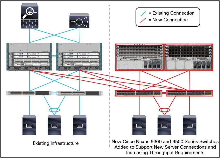
Contents
Introduction .............................................................................................................................................................. 4
What You Will Learn ............................................................................................................................................. 4
Disclaimer ............................................................................................................................................................. 4
Why Cisco Nexus 9000 Series Switches .............................................................................................................. 4
About Cisco Nexus 9000 Series Switches ............................................................................................................ 5
Cisco ACI Readiness ............................................................................................................................................... 6
What Is Cisco ACI? ............................................................................................................................................... 6
Converting Cisco Nexus 9000 NX-OS Mode to ACI Mode ................................................................................... 7
Data Center Design Evolution ................................................................................................................................ 8
Traditional Data Center Design ............................................................................................................................. 8
Spanning Tree Support .................................................................................................................................... 9
Commercial Collapsed Designs ....................................................................................................................... 9
Layer 2 versus Layer 3 Implications ............................................................................................................... 10
Cisco Layer 2 Design Evolution: Virtual PortChannels ....................................................................................... 12
Virtual Overlays .............................................................................................................................................. 13
Spine-Leaf Data Center Design .......................................................................................................................... 14
Overlay Design ................................................................................................................................................... 15
Additional Cisco Nexus 9000 Feature Support ................................................................................................... 17
Quality of Service ........................................................................................................................................... 17
Multicast ......................................................................................................................................................... 19
SNMP and Supported MIBs ........................................................................................................................... 19
Sample Commercial Topologies .......................................................................................................................... 20
Cisco Nexus 9500 Platform Product Line ........................................................................................................... 20
Cisco Nexus 9300 Platform Product Line ........................................................................................................... 21
Design A: Two Switches ..................................................................................................................................... 22
Design B: Two Aggregation and Two Access Switches ...................................................................................... 23
Design C: Two Aggregation and Four Access Switches ..................................................................................... 25
Design D: Four Aggregation and Four Access Switches with Spine-Leaf ........................................................... 25
Integration with Existing Networks ...................................................................................................................... 26
Access Layer Device Connectivity ...................................................................................................................... 26
Design A Integration ........................................................................................................................................... 26
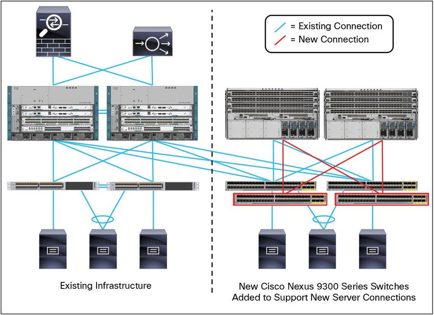
Design B Integration ........................................................................................................................................... 27
Design C and D Integration ................................................................................................................................. 28
Fabric Extender Support ..................................................................................................................................... 30
Storage Design ................................................................................................................................................... 32
End-State Topology ............................................................................................................................................ 35
Example: Cisco Nexus 9000 Series Design and Configuration ......................................................................... 36
Hardware and Software Specifications ............................................................................................................... 36
Basic Network Setup ........................................................................................................................................... 37
ECMP Routing Design ........................................................................................................................................ 39
Server NIC Teaming Design and Configuration .................................................................................................. 40
Overlay Design and Configuration ...................................................................................................................... 44
Why VXLAN? ................................................................................................................................................. 44
How Does VXLAN Work? ............................................................................................................................... 45
Multicast Considerations ................................................................................................................................ 45
Spine (Aggregation) Multicast Configuration .................................................................................................. 46
Leaf (Access) Multicast Configuration ............................................................................................................ 47
Using VXLAN in Commercial Topology .......................................................................................................... 48
Service Design and Configuration....................................................................................................................... 50
Managing and Automating the Fabric ................................................................................................................. 52
Cisco UCS Director ........................................................................................................................................ 52
Cisco Prime Data Center Network Manager .................................................................................................. 53
© 2018 Cisco and/or its affiliates. All rights reserved. This document is Cisco Public Information. Page 2 of 58
Conclusion ............................................................................................................................................................. 55
                        Addendum A: Automation and Programmability ................................................................................................ 55
                          Automation Tools ................................................................................................................................................ 55
                          Automation with Puppet ...................................................................................................................................... 56
                        Helpful Links .......................................................................................................................................................... 56
                          Cisco ACI Mode .................................................................................................................................................. 56
                          External Resources ............................................................................................................................................. 56
                          General Guides ................................................................................................................................................... 56
                          Licensing ............................................................................................................................................................. 57
                          Cisco Nexus 9000 Data Sheets .......................................................................................................................... 57
                          Other Cisco Products .......................................................................................................................................... 57
                          Other Overlays and Protocols ............................................................................................................................. 57
                          Software Release Notes ..................................................................................................................................... 57
                          Transceivers ....................................................................................................................................................... 58
                          Unicast and Multicast Routing............................................................................................................................. 58
                          VXLAN ................................................................................................................................................................ 58

© 2018 Cisco and/or its affiliates. All rights reserved. This document is Cisco Public Information.                                                                                     Page 3 of 58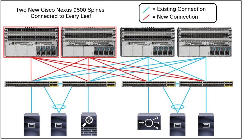
Introduction
                        What You Will Learn
                        The Cisco Nexus® 9000 Series Switches product family makes the next generation of data center switching
                        accessible to customers of any size. This white paper is intended for commercial customers new to Cisco Nexus
                        9000 Series Switches who are curious how the switches might be feasibly deployed in their data centers.

                        This white paper highlights the benefits of Cisco Nexus 9000 Series Switches, outlines several designs suitable for
                        small-to-midsize customer deployments, discusses integration with existing networks, and walks through a
                        topology validated by Cisco for Cisco Nexus 9000 Series Switches, complete with configuration examples.

                        The featured designs are practical for both entry-level insertion of Cisco Nexus 9000 Series Switches, and for
                        existing or growing organizations that are scaling out the data center. The configuration examples transform the
                        logical designs into tangible easy-to-use templates, simplifying deployment and operations for organizations with a
                        small or growing IT staff.

                        Optionally, you can learn how to get started with the many powerful programmability features of Cisco NX-OS from
                        a beginner’s perspective by seeing Addendum A, “Automation and Programmability,” at the end of this document.
                        This white paper also provides many valuable links for further reading about protocols, solutions, and designs
                        discussed. A thorough discussion on the programmability features of Cisco Nexus 9000 Series Switches are out of
                        the scope of this document.

                        Disclaimer
                        Always refer to the Cisco website for the most recent information about software versions, supported configuration
                        maximums, and device specifications at https://www.cisco.com/go/nexus9000.

                        Why Cisco Nexus 9000 Series Switches
                        Cisco Nexus 9000 Series Switches (shown in Figure 1) are ideal for small-to-midsize data centers, offering five key
                        benefits: price, performance, port-density, programmability, and power efficiency.

                        Figure 1.      Cisco Nexus 9000 Series Switches Product Family

© 2018 Cisco and/or its affiliates. All rights reserved. This document is Cisco Public Information.                                 Page 4 of 58
Cisco Nexus 9000 Series Switches are cost-effective by taking a merchant-plus approach to switch design. Both
                        silicon developed by Cisco- plus merchant silicon application-specific integrated circuits (ASICs) Trident II, or T2,
                        power Cisco Nexus 9000 Series Switches. The T2 ASICs also deliver power efficiency gains. Additionally, Cisco
                        Nexus 9000 Series Switches lead the industry in 10 and 40 Gb price-per-port densities. The cost-effective design
                        approach coupled with a rich feature set make Cisco Nexus 9000 Series Switches a great fit for commercial data
                        centers.

                        Licensing is greatly simplified on the Cisco Nexus 9000 Series Switches. At the time of this writing, there are two
                        licenses available: the Enterprise Services Package license enables dynamic routing protocol and VXLAN support,
                        and the Cisco Data Center Network Manager (DCNM) license provides a single-pane-of-glass GUI management
                        tool for the entire data center network. Future licenses may become available as new features are introduced.

                        Cisco Nexus 9000 Series Switches offer powerful programmability features to drive emerging networking models
                        including automation and DevOps, using tools, such as the Cisco NX-OS API (NX-API), as well as Python, Chef,
                        and Puppet.

                        For small-to-midsize commercial customers, the Cisco Nexus 9000 Series Switches product family is the best
                        platform for 1-to-10 Gb migration, 10-to-40 Gb migration, and is an ideal replacement for aging Cisco Catalyst®
                        switches in the data center. The Cisco Nexus 9000 Series Switches can easily be integrated with existing
                        networks. This white paper introduces a design as small as two Cisco Nexus 9000 Series Switches and provides a
                        path to scale out your data center as it grows, highlighting both access and aggregation designs, and spine-leaf
                        designs.

                        About Cisco Nexus 9000 Series Switches
                        The Cisco Nexus 9000 Series consists of larger Cisco Nexus 9500 Series modular switches and smaller Cisco
                        Nexus 9300 Series fixed-configuration switches. The product offerings are discussed in detail later in this white
                        paper.

                        Cisco provides two modes of operation for the Cisco Nexus 9000 Series. Customers can use Cisco NX-OS
                        Software to deploy the Cisco Nexus 9000 Series in standard Cisco Nexus switch environments. Alternately,
                        customers can use the Cisco Application Centric Infrastructure (ACI), which is ready for the hardware infrastructure
                        to take full advantage of an automated, policy-based, systems management approach.

                        In addition to traditional Cisco NX-OS features, such as Cisco virtual PortChannels (vPC), PowerOn Auto
                        Provisioning (POAP), and Nexus 2000 Series Fabric Extenders support, the single-image Cisco NX-OS running on
                        Cisco Nexus 9000 Series Switches introduces several key new features:

                              ●   The intelligent Cisco NX-API provides administrators a way to manage the switch through remote procedure
                                  calls (JSON or XML) over HTTP and/or HTTPS, instead of accessing the Cisco NX-OS command line
                                  directly.
                              ●   Linux shell access enables the switch to be configured through Linux shell scripts, helping automate the
                                  configuration of multiple switches and helping ensure consistency among multiple switches.
                              ●   Continuous operation is maintained through cold and hot patching, which provides fixes between regular
                                  maintenance releases or between the final maintenance release and the end-of-maintenance release, in a
                                  nondisruptive manner (for hot patches).
                              ●   Virtual Extensible LAN (VXLAN) bridging and routing in hardware at full line rate facilitates and accelerates
                                  communication between virtual and physical servers. VXLAN is designed to provide the same Layer 2
                                  Ethernet services as VLANs, but with greater flexibility and at a massive scale.

© 2018 Cisco and/or its affiliates. All rights reserved. This document is Cisco Public Information.                                       Page 5 of 58
For more information about upgrades, see the Cisco Nexus 9000 Series NX-OS Software Upgrade and
                        Downgrade Guide.

                        Cisco Nexus 9000 Series Switches support the plug-in for OpenStack Networking, also known as Neutron. With
                        the plug-in you can build an infrastructure as a service (IaaS) network and to deploy a cloud network. With
                        OpenStack, you can build an on-demand, self-service, multitenant computing infrastructure. However,
                        implementing the OpenStack VLAN networking model across virtual and physical infrastructures can be difficult.

                        The OpenStack Networking extensible architecture supports plugins to configure networks directly. However, when
                        you choose a network plug-in, only that plug-in's target technology is configured. When you are running OpenStack
                        clusters across multiple hosts with VLANs, a typical plug-in configures either the virtual network infrastructure or
                        the physical network, but not both.

                        The Cisco Nexus plug-in solves this difficult problem by including support for configuring both the physical and
                        virtual networking infrastructure. The Cisco Nexus plug-in accepts OpenStack Networking API calls and uses the
                        Network Configuration Protocol (NETCONF) to configure Cisco Nexus devices, as well as Open vSwitch (OVS),
                        which runs on the hypervisor.

                        The Cisco Nexus plug-in configures VLANs on both the physical and virtual network. It also allocates scarce VLAN
                        IDs by deprovisioning them when they are no longer needed and reassigning them to new tenants whenever
                        possible. VLANs are configured so that virtual machines running on different virtualization (computing) hosts that
                        belong to the same tenant network transparently communicate through the physical network. In addition,
                        connectivity from the computing hosts to the physical network is trunked to allow traffic only from the VLANs that
                        are configured on the host by the virtual switch.

                        For more information, see OpenStack at Cisco.

                        This white paper focuses on basic design, integration of features, such as vPC, VXLAN, access layer device
                        connectivity, and Layer 4-7 service insertion. Please refer to the addendum For an introduction to the advanced
                        programmability features of Cisco NX-OS on Cisco Nexus 9000 Series Switches, see Addendum A, “Automation
                        and Programmability,” in this document. Other features are out of the scope of this white paper.

                        Cisco ACI Readiness
                        What Is Cisco ACI?
                        The future of networking with Cisco Application Centric Infrastructure (ACI) is about providing a network that is
                        deployed, monitored, and managed in a way that supports rapid application change. ACI does this through the
                        reduction of complexity and a common policy framework that can automate provisioning and managing resources.

                        Cisco ACI works to solve the business problem of slow application deployment due to focus on primarily technical
                        network provisioning and change management problems by enabling rapid deployment of applications to meet
                        changing business demands. Cisco ACI provides an integrated approach by providing application-centric end-to-
                        end visibility from a software overlay down to the physical switching infrastructure while accelerating and optimizing
                        Layer 4-7 service insertion to build a system that brings the language of applications to the network.

                        Cisco ACI delivers automation, programmability, and centralized provisioning by allowing networks to be
                        automated and configured based on business-level application requirements. Cisco ACI provides accelerated,
                        cohesive deployment of applications across network and Layer 4-7 infrastructure, and enables visibility and
                        management at the application level. Advanced telemetry for visibility into network health and simplified day two
                        operations also opens up troubleshooting to the application itself.

© 2018 Cisco and/or its affiliates. All rights reserved. This document is Cisco Public Information.                                    Page 6 of 58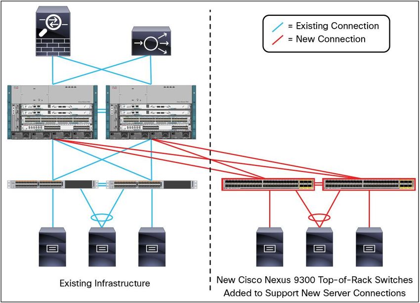
The Cisco ACI diverse and open ecosystem is designed to plug in to any upper-level management or orchestration
                        system and attract a broad community of developers. With the integration and automation of both Cisco and third-
                        party Layer 4-7 virtual and physical service devices, you can use a single tool to manage the entire application
                        environment.

                        With the Cisco ACI mode, customers can deploy networks based on application requirements in the form of
                        policies, removing the need to translate the complexity of current network constraints. In tandem, Cisco ACI
                        ensures security and performance while maintaining complete visibility into application health on both virtual and
                        physical resources.

                        Figure 2 highlights how the network communication might be defined for a three-tier application from the Cisco ACI
                        GUI interface. The network is defined in terms of the needs of the application by mapping out who is allowed to talk
                        to whom and what they are allowed to talk about by defining a set of policies, or contracts, inside an application
                        profile, instead of configuring lines and lines of command line interface (CLI) code on multiple switches, routers,
                        and appliances.

                        Figure 2.      Example of Three-Tier Application Policy

                        Converting Cisco Nexus 9000 NX-OS Mode to ACI Mode
                        This white paper features the Cisco Nexus 9000 Series Switches in NX-OS (standalone) mode. However, the
                        Cisco Nexus 9000 hardware is ready for Cisco ACI. Cisco Nexus 9300 switches and many of the Cisco Nexus
                        9500 line cards can be converted to ACI mode.

                        The Cisco Nexus 9000 Series Switches are the foundation of the Cisco ACI architecture and provide the network
                        fabric. A new operating system is used by the Cisco Nexus 9000 switches running in ACI mode. The switches are
                        then coupled with a centralized controller called the Cisco Application Policy Infrastructure Controller (APIC) and its
                        open API. The Cisco APIC is the unifying point of automation, telemetry, and management for the Cisco ACI fabric,
                        enabling an application policy model approach to the data center.

© 2018 Cisco and/or its affiliates. All rights reserved. This document is Cisco Public Information.                                    Page 7 of 58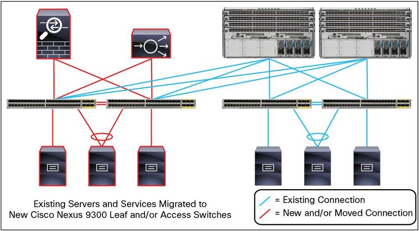
Conversion from standalone NX-OS mode to ACI mode on the Cisco Nexus 9000 switch is out of the scope of this
                        white paper. For more information about the ACI mode on the Cisco Nexus 9000 Series Switches, see the Cisco
                        ACI homepage.

                        Data Center Design Evolution
                        Cisco Nexus 9000 Series Switches can be used in a number of potential designs in a midsize commercial data
                        center. Cisco Nexus 9000 Series Switches can be used as end-of-row or top-of-rack access layer switches, as
                        aggregation or core switches in traditional hierarchical two- or three-tier network designs, or deployed in a modern
                        leaf-spine architecture. This white paper discusses both access and aggregation designs and leaf-spine designs.

                        Traditional Data Center Design
                        Traditional data centers are built on a three-tier architecture with core, aggregation, and access layers, or a two-tier
                        collapsed core with the aggregation and core layers combined in one layer, as shown in Figure 3. This architecture
                        accommodates a north-south traffic pattern where client data comes in from a WAN or the Internet to be processed
                        by a server in the data center and is then pushed back out of the data center. This is common for applications,
                        such as web services, where most communication is between an external client and an internal server. The north-
                        south traffic pattern permits hardware oversubscription, because most traffic is funneled in and out through the
                        lower-bandwidth WAN or Internet bottleneck.

                        Figure 3.      Traditional Three-Tier Design

                        More common in a midsized commercial data center is a collapsed two-tier design where there are two main
                        design decisions:

                              ●   Layer 2/Layer 3 boundary is at the aggregation layer.
                              ●   Layer 3 is down to the access layer (routed access).

© 2018 Cisco and/or its affiliates. All rights reserved. This document is Cisco Public Information.                                     Page 8 of 58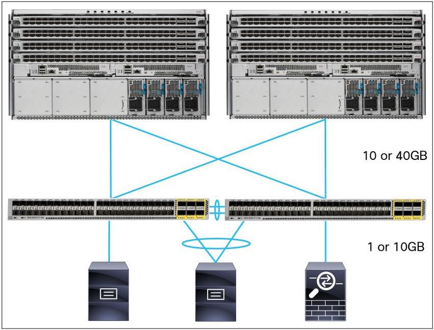
The factors used in making a decision about the Layer 2-Layer 3 boundary is discussed with the designs, but some
                        of the major considerations of each design are shown in Table 1:

                        Table 1.        Major Considerations of Each Design

                         Consideration                         Layer 3 at Core                                         Layer 3 at Access
                         Multipathing                          One active path per VLAN due to spanning tree           Equal cost multipathing through dynamic routing
                                                               mode between access and core switches                   protocol between access and core switches
                         STP                                   More Layer 2 links, therefore more loops and links to   No STP running north of access layer
                                                               block
                         Layer 2 reach                         Greater Layer 2 reachability for workload mobility      Layer 2 adjacency limited to devices connected to the
                                                               and clustering applications                             same access layer switch
                         Convergence time                      Spanning tree mode generally has a slower               Dynamic routing protocols generally have a faster
                                                               convergence time than a dynamic routing protocol        convergence time than STP

                        Spanning Tree Support
                        The Cisco Nexus 9000 Series supports two spanning tree modes: Rapid per VLAN spanning tree plus (PVST+),
                        which is the default mode, and MST (Multiple Spanning Tree).

                        The Rapid PVST+ protocol is the IEEE 802.1w standard, Rapid Spanning Tree Protocol (RSTP), implemented on a
                        per-VLAN basis. Rapid PVST+ interoperates with the IEEE 802.1Q VLAN standard, which mandates a single STP
                        instance for all VLANs, rather than per VLAN. Rapid PVST+ is enabled by default on the default VLAN (VLAN1)
                        and on all newly created VLANs on the device. Rapid PVST+ interoperates with devices that run legacy IEEE
                        802.1D STP. RSTP is an improvement on the original STP standard, 802.1D, which allows faster convergence.

                        MST maps multiple VLANs onto a spanning tree instance, with each instance having a spanning tree topology
                        independent of other instances. This architecture provides multiple forwarding paths for data traffic, enables load
                        balancing, and reduces the number of STP instances required to support a large number of VLANs. MST improves
                        the fault tolerance of the network because a failure in one instance does not affect other instances. The MST mode
                        provides rapid convergence through explicit handshaking because each MST instance uses the IEEE 802.1w
                        standard. MST mode improves spanning tree operation and maintains backward compatibility with the original
                        802.1D Spanning Tree and Rapid per-VLAN spanning tree (Rapid PVST+) protocol.

                        Commercial Collapsed Designs
                        The following Figures 4, 5, and 6 depict two-tier designs, with Layer 3 at the aggregation layer and Layer 2 at the
                        access and up to the aggregation layer, found frequently in commercial data centers. Some customers may not
                        require a complete two-tier design and often deploy a pair of switches as the collapsed data center architecture.

                        Figure 4.       Traditional One-Tier Collapsed Design

© 2018 Cisco and/or its affiliates. All rights reserved. This document is Cisco Public Information.                                                                Page 9 of 58
Figure 5.      Traditional Two-Tier Small Access-Aggregation Design

                        Figure 6.      Traditional Two-Tier Medium Access-Aggregation Design

                        Customers can also have the small collapsed design replicated to another rack or building with a Layer 3
                        connection between the pods (Figure 7).

                        Figure 7.      Layer 2 Access, Layer 3 Connection between Pods

                        Layer 2 versus Layer 3 Implications
                        Data center traffic patterns are changing. Today, more traffic moves east-west from server to server through the
                        access layer as servers need to talk to each other and consume services in the data center. This shift is primarily
                        driven by the evolution of application design. Many modern applications need to talk to each other in the data
                        center. Applications driving this shift include big data’s often-distributed processing design (for example, Hadoop),
                        live virtual machine or workload migration (for example, VMware vMotion), server clustering (for example, Microsoft
                        Cluster Services), and multitier applications. The oversubscribed hardware now isn’t sufficient for the east-west 10-
                        to-10 Gb communications. Additionally, east-west traffic is often forced up through the core or aggregation layer,
                        taking a suboptimal path.

© 2018 Cisco and/or its affiliates. All rights reserved. This document is Cisco Public Information.                                  Page 10 of 58
Spanning tree is another hindrance in the traditional three-tier data center design. Spanning tree is required to
block loops in flooding Ethernet networks so that frames are not forwarded endlessly. Blocking loops means
blocking links, leaving only one active path (per VLAN). Blocked links severely impact available bandwidth and
oversubscription. This can also force traffic to take a suboptimal path, because spanning tree can block a more
desirable path.
Figure 8. Suboptimal Path between Servers in Different Pods Due to Spanning Tree Blocked Links
Addressing these issues can include upgrading hardware to support 40 or 100 Gb interfaces, bundling links into
Cisco Port Channels to appear as one logical link to spanning tree or moving the Layer 2-Layer 3 boundary down
to the access layer to limit the reach of spanning tree. Using a dynamic routing protocol between the two layers
allows all links to be active, and have fast reconvergence and equal-cost multipathing (ECMP).
Figure 9. Two-Tier Routed Access Layer Design
The trade-off in moving Layer 3 routing to the access layer in a traditional Ethernet network is this limits Layer 2
reachability. Applications, such as virtual machine workload mobility and some clustering software, require Layer 2
adjacency between source and destination servers. By routing at the access layer, only servers connected to the
same access switch with the same VLANs trunked down are Layer 2 adjacent. However, the alternative of
spanning a VLAN across the entire data center for reachability is problematic due to Ethernet’s broadcast nature
and spanning tree reconvergence events.
© 2018 Cisco and/or its affiliates. All rights reserved. This document is Cisco Public Information. Page 11 of 58Figure 10. Routed Access Layer Limits Layer 2 Reachability
Cisco Layer 2 Design Evolution: Virtual PortChannels
Over the past few years many customers have sought ways to move past the limitations of spanning tree. The first
step on the path to modern data centers based on Cisco Nexus solutions came in 2008 with the advent of Cisco
virtual PortChannels (vPC). A vPC allows a device to connect to two different physical Cisco Nexus switches using
a single logical Cisco PortChannel interface.
Prior to Cisco vPC, Cisco PortChannels generally had to terminate on a single physical switch. Cisco vPC gives
the device active-active forwarding paths. Because of the special peering relationship between the two Cisco
Nexus switches, spanning tree does not see any loops, leaving all links active. To the connected device, the
connection appears as a normal Cisco PortChannel interface, requiring no special configuration. The industry
standard term is called Multi-Chassis EtherChannel; the Cisco Nexus implementation is called vPC.
Figure 11. vPC Physical Versus Logical Topology
Cisco vPC deployed on a spanning tree Ethernet network is a very powerful way to curb the number of blocked
links, and thereby increasing available bandwidth. Cisco vPC on Cisco Nexus 9000 switches is a great solution for
commercial customers, and those satisfied with current bandwidth, oversubscription, and Layer 2 reachability
requirements.
© 2018 Cisco and/or its affiliates. All rights reserved. This document is Cisco Public Information. Page 12 of 58Two of the sample small-to-midsized traditional commercial topologies are depicted using vPCs in Figures 12 and
13. These designs leave the Layer 2-Layer 3 boundary at the aggregation to permit broader Layer 2 reachability,
but all links are active because spanning tree does not see any loops to block. Details about the special vPC
peering relationship between the Nexus switches is discussed later in this white paper.
Figure 12. Traditional One-Tier Collapsed Design with Cisco vPC
Figure 13. Traditional Two-Tier Design with Cisco vPC
Virtual Overlays
Customers with a two- or three-tier design looking to route to the access layer yet still maintain Layer 2 reachability
between servers can take the next step in the data center evolution by implementing a virtual overlay fabric. In a
Cisco Nexus 9000 fabric design, dynamic routing is configured between switches down to the access layer so that
all links are active. This eliminates the need for spanning tree on the fabric and enables ECMP through the
dynamic routing protocol.
A virtual overlay fabric called Virtual Extensible LAN (VXLAN) can be used to provide Layer 2 adjacencies over the
Layer 3 fabric for servers and other devices that require Layer 2 reachability in the Cisco Nexus 9000 design.
Combining VXLAN and a dynamic routing protocol offers the benefits of an intelligent Layer 3 routing protocol, yet
it can also provide Layer 2 reachability across all access switches for applications such as virtual machine
workload mobility and clustering.
© 2018 Cisco and/or its affiliates. All rights reserved. This document is Cisco Public Information. Page 13 of 58Figure 14. VXLAN-Enabled Layer 2 Communication over an Underlying IP Transport Network
The limitations of spanning tree in three-tier designs and the needs of modern applications are driving a shift in
network design towards a spine-leaf or access and aggregation architecture. Two- and three-tier designs are still a
valid and prevalent architecture; spine-leaf architecture provides another easily integrated option.
Spine-Leaf Data Center Design
Spine-leaf topologies are based on a Clos network architecture. The term originates from Charles Clos at Bell
Laboratories, who published a paper in 1953 that describes a mathematical theory of a multipathing, nonblocking,
multiple-stage network topology to switch telephone calls through.
Today, Clos’s original thoughts on design are applied to the modern spine-leaf topology. Spine-leaf architecture is
typically deployed as two layers: spines (such as an aggregation layer), and leaves (such as an access layer).
Spine-leaf topologies provide high-bandwidth, low-latency, nonblocking server-to-server connectivity.
Leaf (aggregation) switches are what provide devices access to the fabric (the network of spine and leaf switches)
and are typically deployed at the top of the rack. Generally, devices connect to the leaf switches. Devices can
include servers, Layer 4-7 services (firewalls and load balancers), and WAN or Internet routers. Leaf switches do
not connect to other leaf switches (unless running vPC in standalone NX-OS mode). However, every leaf should
connect to every spine in a full mesh. Some ports on the leaf are used for end devices (typically 10 Gb), and some
ports are used for the spine connections (typically 40 Gb).
Spine (aggregation) switches are used to connect to all leaf switches and are typically deployed at the end or
middle of the row. Spine switches do not connect to other spine switches. Spines serve as a backbone
interconnect for leaf switches. Generally, spines only connect to leaves, but when integrating Cisco Nexus 9000
switches with an existing environment, it is acceptable to connect other switches, services, or devices to the
spines.
© 2018 Cisco and/or its affiliates. All rights reserved. This document is Cisco Public Information. Page 14 of 58All devices connected to the fabric are an equal number of hops away from one another. This delivers predictable
latency and high bandwidth between servers. Figure 15 depicts a simple two-tier design.
Figure 15. Two-Tier Design and Connectivity
Another way to think about spine-leaf architecture is by thinking of the spines as a central backbone with all leaves
branching off the spine like a star. Figure 16 depicts this logical representation, which uses identical components in
an alternate visual mapping configuration.
Figure 16. Logical Representation of Two-Tier Design
With Cisco Nexus 9000 Series Switches, small-to-midsize commercial customers can start with a few switches and
implement a pay-as-you-grow model. When more access ports are needed, more leaves (access switches) can be
added. When more bandwidth is needed, more spines (aggregation switches) can be added. The Cisco Nexus
9000 switches are well suited for traditional designs, spine-leaf, or any combination of existing topologies.
Overlay Design
Virtual network overlays partition a physical network infrastructure into multiple logically isolated networks that can
be individually programmed and managed to deliver optimal network requirements.
Small-to-midsize commercial customers may require mobility between data centers, in different pods in a single
data center, and across Layer 3 network boundaries. Virtual network overlays make mobility and Layer 2
reachability possible.
Cisco has had a role in developing multiple overlay networks, each solving a different problem by providing an
innovative solution. For example, Cisco Overlay Transport Virtualization (OTV) provides cross-data center mobility
over Layer 3 Cisco Data Center Interconnect (DCI) networks using MAC-in-IP encapsulation.
© 2018 Cisco and/or its affiliates. All rights reserved. This document is Cisco Public Information. Page 15 of 58In Figure 17 two overlays in use are shown: Cisco OTV on a Cisco ASR 1000 Router for data center–to–data
center connectivity, and VXLAN in the data center. Both provide Layer 2 reachability and extension. Cisco OTV is
also available on the Cisco Nexus 7000 Series Switch.
Figure 17. Virtual Overlay Networks Providing Dynamic Reachability for Applications
For more information on overlays in general, see the “Data Center Overlay Technologies” white paper. For more
information on Cisco OTV, see the Cisco OTV webpage.
Now, the IETF-proposed VXLAN overlay on Cisco Nexus 9000 Series Switches provides Layer 2 connectivity
extension across IP transport in the data center, and easy integration between VXLAN and non-VXLAN
infrastructures. VXLAN enables scalable virtualized and multitenant data center designs over a shared common
physical infrastructure.
Beyond a simple overlay sourced and terminated on the switches, the Cisco Nexus 9000 switch can act as a
hardware-based VXLAN gateway. VXLAN is increasingly popular for virtual networking in the hypervisor for virtual-
machine-to-virtual-machine communication, not just switch to switch. However, many devices are not capable of
supporting VXLAN, such as legacy hypervisors, physical servers, and service appliances, such as firewalls, load
balancers, and storage devices. Those devices need to continue to reside on classic VLAN segments. It is not
uncommon that virtual machines in a VXLAN segment need to access services provided by devices in a classic
VLAN segment. The Cisco Nexus 9000 switch, acting as a VXLAN gateway, can provide the necessary translation.
© 2018 Cisco and/or its affiliates. All rights reserved. This document is Cisco Public Information. Page 16 of 58Figure 18. Cisco Nexus 9000 Leaf Switches Translating VLAN to VXLAN
Today, a data center interconnect (DCI), such as Cisco OTV, must be provided by an outside device. In the next
phase of VXLAN, the Cisco Nexus 9000 switch supports Border Gateway Protocol (BGP) Ethernet VPN (EVPN).
EVPN is a next-generation Layer 2 VPN solution based on a BGP control plane, which can be used as a data
center interconnect to distribute MAC address reachability information across the core or provider IP network.
For more information, see the paper “IETF BGP MPLS Based Ethernet VPN” (draft).
Basic VXLAN bridging for Layer 2 extension between leaf, or access, switches is the featured design in this white
paper, and is discussed in more depth later.
Additional Cisco Nexus 9000 Feature Support
While many new and important features have been discussed, it is important to highlight the additional features
support on the Cisco Nexus 9000 Series Switches, such as quality of service (QoS), multicast, and Simple Network
Management Protocol (SNMP) and supported MIBs.
Quality of Service
New applications and evolving protocols are changing the QoS demands in modern data centers. High-frequency
trading floor application are very sensitive to latency, while high-performance computing is typically characterized
by bursty, many-to-one east-west traffic flows. Applications, such as storage, voice, and video, also require special
and different treatment in any data center.
Like the other members of the Cisco Nexus family, the Cisco Nexus 9000 Series Switches support QoS
configuration through Cisco Modular QoS CLI (MQC), which involves identifying traffic using class maps based on
things such as protocol or packet header markings, defining how to treat different classes through policy maps by
possibly marking packets, queuing, or scheduling, and lastly applying policy maps to either interfaces or the entire
system using the service policy command. QoS is enabled by default and does not require a license.
Unlike Cisco IOS®, Cisco NX-OS on the Cisco Nexus 9000 switch uses three different types of policy maps
depending on the QoS feature you are trying to implement. The three types of Cisco NX-OS QoS and their primary
usages include:
● Type QoS:
◦ Classification
◦ Marking
◦ Policing
© 2018 Cisco and/or its affiliates. All rights reserved. This document is Cisco Public Information. Page 17 of 58● Type Queuing:
◦ Buffering
◦ Queuing
◦ Scheduling
● Type Network-QoS:
◦ Systemwide settings
◦ Congestion control
◦ Pause behavior
Type network-QoS policy-maps are applied only systemwide, whereas type QoS and type queuing can each be
applied simultaneously on a single interface, one each ingress and egress for a total of four QoS polices per
interface, if required.
On the Cisco Nexus 9500 switch, ingress traffic can be classified based on attributes such as header address
fields, 802.1p CoS (class of service), IP precedence, differentiated services code point (DSCP) values, or matched
based on access control lists (ACLs). After classified, traffic can be assigned to one of four QoS groups. The QoS
groups serve as an internal identification of traffic classes that is used for subsequent QoS processes as packets
go through the system. On ingress, the Cisco Nexus 9500 switch can also remark CoS, IP precedence, and DSCP,
and perform class-based policing.
Egress, the Cisco Nexus 9500 switch uses a simple queuing architecture and does not use virtual output queues
(VoQs) on ingress line card ports like other Cisco Nexus platforms. If egress ports are congested, packets are
directly queued in the buffer of the egress line card, greatly simplifying system buffer management and queuing
implementation. The Cisco Nexus 9500 switch can support up to six traffic classes on egress (four user-defined
classes identified by QoS-group IDs, a CPU control traffic class, and a SPAN traffic class). Each user-defined class
can have a unicast queue and a multicast queue per egress port. The 12 MB buffer on a network forwarding
engine (NFE), the Trident II ASIC (application-specific integrated circuit), is shared among the local ports. The
buffer’s resources are dynamically shared by ingress and egress traffic. The switch software has a mechanism to
meter and limit buffer utilization per egress port. This ensures that no single port can consume more than its fair
share of the buffer memory leading to buffer starvation of other ports.
Additionally, egress, the Cisco Nexus 9500 switch provides up to three priority-based flow control no-drop queues,
up to three strict priority queues, and the ability to enable weighted random early detection (WRED) or Explicit
Congestion Notification (ECN) instead of the default tail drop queue management.
The Cisco ACI ready leaf line cards have an additional 40 MB buffer in each of their Cisco ACI leaf engines (ALEs).
Allocated to fabric bound traffic is 10 MB of the buffer. The remaining 30 MB is allocated to egress traffic from
fabric modules and locally switched traffic from higher-speed ingress port to a lesser-speed egress port.
This 30 MB buffer is used for extended output queues for unicast traffic. The NFE communicates the unicast queue
status to the Cisco ALE through an out-of-band flow control (OOBFC) signaling channel. When an egress queue
exceeds the configured threshold, the NFE sends an OOBFC signal to instruct the Cisco ALE to stop forwarding
traffic for this queue and start queuing packets in its own buffer. After receiving this signal, the Cisco ALE starts to
form the extended output queue for this traffic class on the given egress port. When the egress queue length is
reduced to the configured restart threshold, the NFE sends another OOBFC signal to direct the Cisco ALE to
resume transmitting traffic for this particular queue.
© 2018 Cisco and/or its affiliates. All rights reserved. This document is Cisco Public Information. Page 18 of 58● For more details on unicast and multicast packet forwarding through the ASICs, see the white paper, “Cisco
Nexus 9500 Series Switches Architecture.”
For other QoS considerations in a mixed LAN and storage environment, for example, see the Cisco Nexus 9000
Series NX-OS Quality of Service Configuration Guide, Release 6.0.
Multicast
The Cisco Nexus 9500 platform provides high-performance, line rate Layer 2 and Layer 3 multicast throughput with
low latency at scale at up to 8000 multicast routes with multicast routing enabled. The Cisco Nexus 9500 platform
optimizes multicast lookup and replication by performing IP-based lookup for Layer 2 and Layer 3 multicast to
avoid common aliasing problems in multicast IP-to-MAC encoding.
The Nexus 9500 platform supports Internet Group Management Protocol (IGMP) versions 1, 2, and 3, Protocol-
Independent Multicast (PIM) sparse mode, anycast rendezvous point, and Multicast Source Discovery Protocol
(MSDP).
SNMP and Supported MIBs
The Simple Network Management Protocol (SNMP) provides a standard framework and language to manage
devices on the network, including the Cisco Nexus 9000 Series Switches. The SNMP manager controls and
monitors the activities of network devices using SNMP. The SNMP agent lives in the managed device and reports
the data to the managing system. The agent on the Cisco Nexus 9000 Series Switches must be configured to talk
to the manager. MIBs are a collection of managed objects by the SNMP agent. The Cisco Nexus 9000 Series
Switches supports SNMP v1, v2c, and v3. The Cisco Nexus 9000 Series Switches can also support SNMP over
IPv6.
SNMP generates notifications about the Cisco Nexus 9000 Series Switches to send to the manager, for example,
notifying the manager when a neighboring router is lost. A trap notification is sent from the agent on the Cisco
Nexus 9000 switch to the manager, who does not acknowledge the message. A notification to inform is
acknowledged by the manager. Table 2 provides the SNMP traps enabled by default.
Table 2. SNMP Traps Enabled by Default on Cisco Nexus 9000 Series Switches
Trap Type Description
generic : coldStart
generic : warmStart
entity : entity_mib_change
entity : entity_module_status_change
entity : entity_power_status_change
entity : entity_module_inserted
entity : entity_moudle_removed
entity : entity_unrecognised_module
entity : entity_fan_status_change
entity : entity_power_out_change
link : linkDown
link : linkup
link : extended-linkDown
link : extended-linkUp
link : cieLinkDown
link : cieLinkUp
link : delayed-link-state-change
© 2018 Cisco and/or its affiliates. All rights reserved. This document is Cisco Public Information. Page 19 of 58Trap Type Description
rf : redundancy_framework
license : notify-license-expiry
license : notify-no-license-for-feature
license : notify-licensefile-missing
license : notify-license-expirty-warning
upgrade : UpgradeOpNotifyOnCompletion
upgrade : UpgradeJobStatusNotify
rmon : risingAlarm
rmon : fallingAlarm
rmon : hcRisingAlarm
rmon : hcFallingAlarm
entity : entity_sensor
On a Cisco Nexus 9000 switch, Cisco NX-OS supports stateless restarts and is also aware of virtual routing and
forwarding (VRF). Using SNMP does not require a license.
For a list of supported MIBs on the Cisco Nexus 9000 Series Switches, see this list.
For configuration help, see the section “Configuring SNMP” in the Cisco Nexus 9000 Series NX-OS System
Management Configuration Guide, Release 6.0.
Sample Commercial Topologies
A spine-leaf or access-aggregation architecture using 10 and 40 Gigabit Ethernet is designed to handle the shift to
east-west traffic patterns in the data center, limit the scope of spanning tree by routing between the layers, provide a
loop-free all-links-active topology, perform ECMP, and optionally provide a virtual overlay for Layer 2 reachability
using VXLAN.
A spine-leaf design is not required when deploying Cisco Nexus 9000 switches, and the topology can also be
thought of as an access-aggregation architecture, as referred to interchangeably throughout this white paper.
The Cisco Nexus 9000 Series Switches portfolio provides a wide array of switches to choose from. Design
considerations include desired throughput, oversubscription ratio, estimated growth, server traffic patterns,
application requirements, and more.
This section is about the Cisco Nexus 9000 Series Switches portfolio and describes several designs suitable for
small-to-midsize commercial data centers. This section also shows simple network topologies. Sample Commercial
Topologies demonstrates how these design options can be integrated with an existing network later in this white
paper.
Cisco Nexus 9500 Platform Product Line
The Cisco Nexus 9500 platform modular switches are typically deployed as spines (aggregation or core switches)
in commercial data centers. Figure 19 lists the line cards available in the Cisco Nexus 9500 chassis in NX-OS
standalone mode at the time of writing. (Line cards for only Cisco ACI have been removed.)
© 2018 Cisco and/or its affiliates. All rights reserved. This document is Cisco Public Information. Page 20 of 58Figure 19. Cisco Nexus 9500 Line Card Types
Note: For the latest product information, see the Cisco Nexus 9500 data sheets . Line card availability may have
changed since the time of this writing.
Cisco Nexus 9300 Platform Product Line
The Cisco Nexus 9300 platform fixed-configuration switches are typically deployed as leaves (access switches).
Some Cisco Nexus 9300 switches are semimodular by providing an uplink module slot for additional ports. The
following figure lists the Cisco Nexus 9300 chassis that support NX-OS standalone mode available at the time of
writing.
Figure 20. Cisco Nexus 9300 Chassis Offerings
Note: For the latest product information, see the Cisco Nexus 9300 data sheets . Switch availability may have
changed since the time of this writing.
© 2018 Cisco and/or its affiliates. All rights reserved. This document is Cisco Public Information. Page 21 of 58Design A: Two Switches
Small commercial customers can deploy a single pair of Cisco Nexus 9300 switches. vPCs can be configured on
the Cisco Nexus 9300 switches, enabling connected devices to have two active, redundant paths to each switch
(Figure 21).
Figure 21. Two-Switch Small Business Deployment
The topology depicts a pair of fixed 1 rack unit (1RU) Cisco Nexus 9372PX Switches. Each Cisco Nexus 9372PX
Switch provides 48 ports of 1/10 Gigabit Ethernet with enhanced small form-factor pluggable (SFP+) Transceivers
and six Quad (4-channel) Small Form-factor Pluggable (QSFP+) 40 Gb ports. There is also a 10GBASE-T version
of the switch available if twisted pair RJ-45 connectors are desired over SFP+ for 10 Gb. This design provides a
total of 108 ports in a 2RU footprint, supporting 1 Gb, 10 Gb, and 40 Gb interfaces.
If the 40 Gb interfaces are not required, the ports can be converted to 10 Gb interfaces using Cisco QSFP to SFP
or SFP+ Adapter (QSA) Module. The Cisco QSA module converts a 40 Gb QSFP port to a 1 Gb SFP or 10 Gb
SFP+ port. Customers have the flexibility to use any SFP+ or SFP module or cable to connect to a lower-speed
port. This flexibility allows a cost-effective transition to 40 Gb over time. The Cisco QSA module supports all SFP+
optics and cable reaches and several 1 Gb SFP modules.
Figure 22. Cisco QSA Module Empty (Left); SFP or SFP+ Inserted (Right)
For more information about Cisco QSA modules, see the Cisco QSA data sheet.
For information about savings on 10 Gb interfaces, Cisco SFP+ Copper Twinax direct-attach cables for distances
up to 10 meters, click here Twinax cables (Figure 23) provide significant savings over traditional 10 GB fiber optic
transceivers and cabling.
Figure 23. Cisco Direct-Attach Twinax Copper Cable Assembly with SFP+ Connectors
© 2018 Cisco and/or its affiliates. All rights reserved. This document is Cisco Public Information. Page 22 of 58For more information on all 10 Gb SFP+ cable options, see the Cisco 10GBase SFP Modules data sheet.
Always check the Cisco Transceiver Modules Compatibility Information webpage for the most up-to-date
information about chassis support.
With a two-switch design, small businesses can reap the benefits of the Cisco Nexus 9000 solution while taking
advantage of a small, affordable footprint. Over time, as the data center grows and the need arises for more
throughput, customers can expand the design by adding more leaves (access switches), or they can choose to
include Cisco Nexus 9500 platform switches in the aggregation, or spine layer, which is the next featured topology.
Design B: Two Aggregation and Two Access Switches
A simple two-spine (aggregation) and two-leaf (access) design provides a satisfactory entry point for small-to-
midsize customers requiring more bandwidth and room for future expansion as shown in Figure 24.
Figure 24. Two-Aggregation Two-Access Commercial Design for Small-to-Medium-Sized Businesses
In the leaf or access layer, the topology shown here depicts a pair of fixed 1RU Cisco Nexus 9372PX Switches.
Each Cisco Nexus 9372PX Switch provides 48 ports of 1/10 Gigabit Ethernet with SFP+ transceivers and six
QSFP+ 40 Gb ports. There is also a 10GBASE-T version of the switch available if twisted pair RJ-45 connectors
are desired over SFP+ for 10 Gb.
In the spine or aggregation layer, the topology depicts two Cisco Nexus N9K-C9504 chassis with N9K-X9536PQ
line cards. The line cards supply 36 QSFP+ 40 Gb each, used to connect to the leaves. The 9536PQ 36-port line
cards open the door for future growth when more leaves are added for access ports, and leave the door open for
transition to ACI mode.
For the latest comparison between line cards, check out the Cisco Nexus 9000 Series Switches Compare Models
tool.
© 2018 Cisco and/or its affiliates. All rights reserved. This document is Cisco Public Information. Page 23 of 58The Cisco QSA 40-to-10 Gb modules can also be used in this design as you transition from 10 Gb to 40 Gb.
Alternately, Cisco provides a low-cost 40 Gb transceiver called a BiDi that eases the move from 10 Gb to 40 Gb.
Existing short-reach 40 Gb transceivers use connectors that require 12 strands of fiber through a multifiber push-on
(MPO) connector. Unfortunately existing 10 Gb fiber deployments and patch panels use Lucent connector (LC)-to-
LC multimode fiber. Upgrading from 10 Gb to 40 Gb fiber can be an expensive endeavor if all transceivers, cabling,
and patch panels had to be replaced.
Figure 25. Existing 40 Gb 12-Strand Fiber Cable and Connectors
As an alternative, the Cisco 40G QSFP BiDi transceiver (Figure 25) addresses the challenges of the fiber
infrastructure by providing the ability to transmit full-duplex 40 Gb over a standard OM3 or OM4 multimode fiber
with LC connectors. The Cisco BiDi transceiver can reuse existing 10 Gb fiber cabling, instead of deploying a new
fiber infrastructure. The Cisco BiDi optic transceiver provides an affordable, simple upgrade path to 40 Gb at
almost the same cost as 10 Gb fiber today.
Figure 26. Cisco QSFP BiDi Transceiver
Figure 27. Cisco BiDi Fiber Connectivity and Speed
For more information about Cisco BiDi optics, see the Cisco QSFP BiDi Technology white paper.
© 2018 Cisco and/or its affiliates. All rights reserved. This document is Cisco Public Information. Page 24 of 58You can also read